1
HP ProLiant ML570 Generation 3 Server
Maintenance and Service Guide
March 2005 (First Edition)
Part Number 374185-001
© Copyright 2005 Hewlett-Packard Development Company, L.P.
The information contained herein is subject to change without notice. The only warranties for HP products
and services are set forth in the express warranty statements accompanying such products and services.
Nothing herein should be construed as constituting an additional warranty. HP shall not be liable for
technical or editorial errors or omissions contained herein.
Microsoft, Windows, and Windows NT are U.S. registered trademarks of Microsoft Corporation.
Linux is a U.S. registered trademark of Linus Torvalds.
HP ProLiant ML570 Generation 3 Server Maintenance and Service Guide
March 2005 (First Edition)
Part Number 374185-001
Audience assumptions
This guide is for an experienced service technician. HP assumes you are qualified in the servicing
of computer equipment and trained in recognizing hazards in products with hazardous energy
levels and are familiar with weight and stability precautions for rack installations.
3
Contents
Illustrated parts catalog
7
Customer self repair ............................................................................................................................. 7
Mechanical components....................................................................................................................... 8
System components............................................................................................................................ 11
Removal and replacement procedures
15
Required tools .................................................................................................................................... 15
Safety considerations ......................................................................................................................... 16
Preventing electrostatic discharge .......................................................................................... 16
Server warnings and cautions ................................................................................................. 16
Preparation procedures....................................................................................................................... 17
Extending the server from the rack......................................................................................... 18
Powering down the server ...................................................................................................... 20
Access panel ........................................................................................................................... 21
Removing the server from the rack......................................................................................... 21
Unlocking and removing the tower bezel ............................................................................... 23
Removing the rack bezel ........................................................................................................ 24
Air baffle ................................................................................................................................ 25
Center wall.............................................................................................................................. 26
Redundant hot-plug power supply.......................................................................................... 27
Hard drive blank ................................................................................................................................ 28
Hot-plug hard drives .......................................................................................................................... 29
Diskette drive blank ........................................................................................................................... 30
Diskette drive ..................................................................................................................................... 31
Optical device .................................................................................................................................... 32
Hot-plug fans ..................................................................................................................................... 33
Expansion boards ............................................................................................................................... 34
Memory options ................................................................................................................................. 37
General memory configuration requirements ......................................................................... 37
Hot-plug mirrored memory..................................................................................................... 42
Hot-plug RAID memory......................................................................................................... 44
Memory boards and DIMMs .................................................................................................. 45
Processor ............................................................................................................................................ 49
PPM ................................................................................................................................................... 52
SCSI backplane board........................................................................................................................ 53
System board...................................................................................................................................... 55
Power backplane ................................................................................................................................ 57
4
HP ProLiant ML570 Generation 3 Server Maintenance and Service Guide
Tape drive blank ................................................................................................................................ 57
Tape drive .......................................................................................................................................... 58
Battery................................................................................................................................................ 59
Re-entering the server serial number and product ID ........................................................................ 61
Server cabling
63
Storage device cabling guidelines...................................................................................................... 63
Cable connector identification ........................................................................................................... 64
SCSI cabling ...................................................................................................................................... 65
Standard SCSI cabling to the SCSI ports................................................................................ 65
External SCSI cabling configuration ...................................................................................... 65
Tape drive cabling to the USB port.................................................................................................... 67
RILOE II cabling ............................................................................................................................... 67
Diagnostic tools
69
SmartStart software............................................................................................................................ 69
SmartStart Scripting Toolkit .............................................................................................................. 70
HP Instant Support Enterprise Edition ............................................................................................... 71
Option ROM Configuration for Arrays.............................................................................................. 71
HP ROM-Based Setup Utility............................................................................................................ 72
ROMPaq utility.................................................................................................................................. 72
System Online ROM flash component utility .................................................................................... 72
Integrated management log ................................................................................................................ 73
Integrated Lights-Out technology ...................................................................................................... 74
Automatic server recovery ................................................................................................................. 74
HP Systems Insight Manager ............................................................................................................. 75
HP Insight Diagnostics....................................................................................................................... 75
USB support....................................................................................................................................... 76
Internal USB functionality...................................................................................................... 76
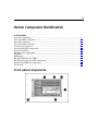
Server component identification
77
Front panel components ..................................................................................................................... 77
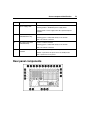
Front panel LEDs and buttons............................................................................................................ 78
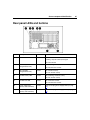
Rear panel components ...................................................................................................................... 79
Rear panel LEDs and buttons............................................................................................................. 81
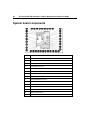
System board components ................................................................................................................. 82
System maintenance switches................................................................................................. 84
DIMM slot locations............................................................................................................... 85
Internal health LED combinations ..................................................................................................... 86
System board LEDs ........................................................................................................................... 87
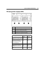
Hot-plug power supply LEDs ............................................................................................................ 89
SCSI IDs ............................................................................................................................................ 90
NMI jumper ....................................................................................................................................... 90
Hot-plug SCSI hard drive LEDs ........................................................................................................ 91
Contents
5
Hot-plug SCSI hard drive LED combinations ................................................................................... 92
Memory board LEDs and components............................................................................................... 93
Fan locations ...................................................................................................................................... 97
Specifications
99
Server specifications .......................................................................................................................... 99
Environmental specifications ........................................................................................................... 100
Hot-plug power supply calculations................................................................................................. 100
DDR SDRAM DIMM specifications............................................................................................... 100
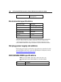
1.44-MB diskette drive specifications.............................................................................................. 101
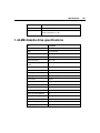
CD-ROM drive specifications.......................................................................................................... 102
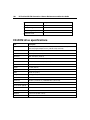
DVD-ROM drive specifications ...................................................................................................... 103
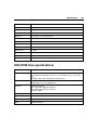
Ultra320 SCSI hard drive specifications.......................................................................................... 105
Acronyms and abbreviations
107
Index
113
7
Illustrated parts catalog
In this section
Customer self repair........................................................................................................................7
Mechanical components .................................................................................................................8
System components ......................................................................................................................11
Customer self repair
What is customer self repair?
HP's customer self-repair program offers you the fastest service under either
warranty or contract. It enables HP to ship replacement parts directly to you so
that you can replace them. Using this program, you can replace parts at your own
convenience.
A convenient, easy-to-use program:
•
An HP support specialist will diagnose and assess whether a replacement
part is required to address a system problem. The specialist will also
determine whether you can replace the part.
•
Replacement parts are express-shipped. Most in-stock parts are shipped the
very same day you contact HP. You may be required to send the defective
part back to HP, unless otherwise instructed.
•
Available for most HP products currently under warranty or contract. For
information on the warranty service, refer to the HP website
(http://h18004.www1.hp.com/products/servers/platforms/warranty/index.htm
l).
For more information about HP's customer self-repair program, contact your
local service provider. For the North American program, refer to the HP website
(http://www.hp.com/go/selfrepair).
Customer replaceable parts are identified in the following tables.
8
HP ProLiant ML570 Generation 3 Server Maintenance and Service Guide
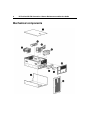
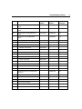
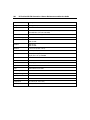
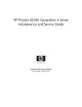
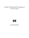
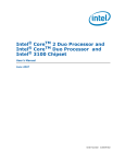
Mechanical components
Illustrated parts catalog
Item
Description
Assembly
Number
Spare Part
Number
Customer
Self Repair
1
Access panel, ProLiant ML570 G3
Server
366264-002
374553-001
Yes
2a
Bezel, Rack, ProLiant ML570 G3
Server
373317-001
374557-001
Yes
2b
Bezel, Tower, ProLiant ML570 G3
Server
373316-001
374556-001
Yes
374550-001
Yes
Plastics Kit, ProLiant ML570 G3
Server
*
•
Hot-plug basket, PCI-X
372583-001
—
*
•
Baffle assembly
353829-001
—
3
•
Bezel assembly, media
373319-001
—
*
•
Retainer, tower bezel
158475-003
—
*
•
Latch, PCI, carbon
228194-001
—
*
•
Latch, PCI, blue
228194-002
—
*
•
Retainer, memory board
366262-001
—
*
•
Retainer, memory board
366263-001
—
*
•
Latch, center wall
366272-001
—
*
•
Latch, center wall
366273-001
—
*
•
Latch, center wall
366274-001
—
*
•
Retainer, PCI, carbon
379046-001
—
*
•
Retainer, PCI, blue
379046-002
—
Hardware Kit, Misc, ProLiant ML570
G3 Server
374551-001
4
Blank, tape drive
373318-001
—
*
Blank, power supply
366450-001
—
*
Blank, CD/DVD/diskette
377569-001
—
5
Cage, memory modules
6
Hold-down, processor power module
8
Center wall
Yes
9
10
HP ProLiant ML570 Generation 3 Server Maintenance and Service Guide
Item
Description
Assembly
Number
Spare Part
Number
Customer
Self Repair
7
Cover, tower, ProLiant ML570 G3
Server
374503-001
377839-001
Yes
9
Cage, fan
*
Kit, rack mount
374503-001
377839-001
Yes
*
Blank, hard drive
302531-001
122759-001
Yes
*
Casters, tower
289720-003
296277-001
Yes
*
Return kit, tower, ProLiant ML570 G3
Server
374554-001
Yes
*
Return kit, rack, ProLiant ML570 G3
Server
374555-001
Yes
*
Screwdriver, Torx, T-15
199630-001
Yes
*Not shown
107473-001
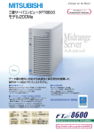
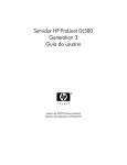
Illustrated parts catalog
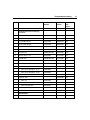
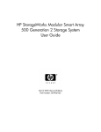
System components
11
12
Item
HP ProLiant ML570 Generation 3 Server Maintenance and Service Guide
Description
Assembly
Number
Spare Part
Number
Customer
Self
Repair
System Components
3
Processor, 3.66 GHz, 1 MB, with
heatsink
376659-002
389027-001
Yes
*
Processor, 3.33 GHz, 8 MB, with
heatsink
376660-001
379982-001
Yes
*
Processor, 3.00 GHz, 8 MB, with
heatsink
376660-002
379981-001
Yes
*
Processor, 3.16 GHz, 1 MB, with
heatsink
376659-001
377840-001
Yes
*
Processor, 2.83 GHz, 4 MB, with
heatsink
376661-001
377840-001
Yes
13
Power Supply, 910/1300 Watt
337667-001
364360-001
Yes
Boards
1
Board, SCSI Backplane, ProLiant
ML570 G3 Server
012076-001
368161-001
No
2
Board, Memory, ProLiant ML570 G3
Server
012073-001
368160-001
Yes
4
Board, Processor Power Module
367240-001
370718-001
Yes
10
Board, Fan/CD/Diskette
012085-001
374547-001
Yes
14
Board, Power Backplane, ProLiant
ML570 G3 Server
012079-001
374546-001
No
15
Board, System, ProLiant ML570 G3
Server
012067-001
368159-001
No
*
Board, PCI Hot-Plug switch
011077-001
230981-001
Yes
Memory
DIMM, PC3200, DDR2
*
a) 512 MB
345112-051
359241-001
Yes
*
b) 1 GB
345113-051
359242-001
Yes
*
c) 2 GB, single rank
345114-061
359243-001
Yes
Illustrated parts catalog
Item
Description
Assembly
Number
Spare Part
Number
Customer
Self
Repair
*
d) 2 GB, dual rank
345114-051
378021-001
Yes
SCSI Ultra320 universal hot-plug
hard drive
5
a) 36.4 GB 15K rpm
271837-016
289241-001
Yes
*
b) 72.8 GB 10K rpm
271837-008
289042-001
Yes
*
c) 72.8 GB 15K rpm
271837-018
289243-001
Yes
*
d) 146.8 GB 10K rpm
271837-010
289044-001
Yes
*
e) 300 GB 10k rpm
271837-021
351126-001
Yes
Removable Media Drives
11
DVD drive, 8x
168003-935/9D1
268795-001
Yes
12
Diskette drive, 3.5 in
263394-001
267132-001
Yes
*
CD-RW drive
294766-9D1/935
337273-001
Yes
374549-001
Yes
Cables
*
Cable kit, power
*
•
Cable, fan power
372618-001
—
*
•
Cable, power backplane, 12 pin
372619-001
—
*
•
Cable, power backplane, 14 pin
372620-001
—
*
•
Cable, power backplane, 22 pin
372621-001
—
*
Cable kit, data
*
•
Cable, fan
372616-001
—
*
•
Cable, power backplane
372617-001
—
*
•
Cable, jacketed, blue
166298-041
—
*
•
Cable, jacketed, yellow
166298-042
—
*
•
Cable, PCI HP
224999-002
—
178968-001
237457-001
374548-001
Yes
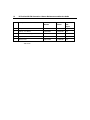
Miscellaneous
*
AC power cord, 15 A, 125 V
Yes
13
14
HP ProLiant ML570 Generation 3 Server Maintenance and Service Guide
Item
Description
Assembly
Number
Spare Part
Number
Customer
Self
Repair
*
AC power cord, C14-C19
287485-001
311582-001
Yes
*
Battery, 3 V, Lithium
166899-001
153099-001
Yes
7
Fan, 120 mm, Hot-plug
364517-001
374552-001
Yes
*
Keyboard, PS/2, US
352750-001
355630-001
Yes
*
Mouse, PS/2
103179-165
311060-001
Yes
*Not shown
15
Removal and replacement procedures
In this section
Required tools...............................................................................................................................15
Safety considerations....................................................................................................................16
Preparation procedures .................................................................................................................17
Hard drive blank ...........................................................................................................................28
Hot-plug hard drives.....................................................................................................................29
Diskette drive blank......................................................................................................................30
Diskette drive................................................................................................................................31
Optical device ...............................................................................................................................32
Hot-plug fans ................................................................................................................................33
Expansion boards..........................................................................................................................34
Memory options............................................................................................................................37
Processor.......................................................................................................................................49
PPM ..............................................................................................................................................52
SCSI backplane board ..................................................................................................................53
System board ................................................................................................................................55
Power backplane...........................................................................................................................57
Tape drive blank ...........................................................................................................................57
Tape drive.....................................................................................................................................58
Battery ..........................................................................................................................................59
Re-entering the server serial number and product ID...................................................................61
Required tools
You need the following items for some procedures:
•
T-10 Torx screwdriver
•
T-15 Torx screwdriver
•
Diagnostics Utility
16
HP ProLiant ML570 Generation 3 Server Maintenance and Service Guide
Safety considerations
Before performing service procedures, review all the safety information.
Preventing electrostatic discharge
To prevent damaging the system, be aware of the precautions you need to follow
when setting up the system or handling parts. A discharge of static electricity
from a finger or other conductor may damage system boards or other staticsensitive devices. This type of damage may reduce the life expectancy of the
device.
To prevent electrostatic damage:
•
Avoid hand contact by transporting and storing products in static-safe
containers.
•
Keep electrostatic-sensitive parts in their containers until they arrive at staticfree workstations.
•
Place parts on a grounded surface before removing them from their
containers.
•
Avoid touching pins, leads, or circuitry.
•
Always be properly grounded when touching a static-sensitive component or
assembly.
Server warnings and cautions
Before installing a server, be sure that you understand the following warnings
and cautions.
WARNING: To reduce the risk of electric shock or damage
to the equipment:
Removal and replacement procedures
•
Do not disable the power cord grounding plug. The grounding
plug is an important safety feature.
•
Plug the power cord into a grounded (earthed) electrical outlet
that is easily accessible at all times.
•
Unplug the power cord from the power supply to disconnect
power to the equipment.
•
Do not route the power cord where it can be walked on or
pinched by items placed against it. Pay particular attention to
the plug, electrical outlet, and the point where the cord extends
from the server.
17
WARNING: To reduce the risk of personal injury from hot
surfaces, allow the drives and the internal system components to
cool before touching them.
CAUTION: Do not operate the server for long periods without
the access panel. Operating the server without the access panel results
in improper airflow and improper cooling that can lead to thermal
damage.
Preparation procedures
To access some components and perform certain service procedures, you must
perform one or more of the following procedures:
•
Extend the server from the rack ("Extending the server from the rack" on
page 18).
If you are performing service procedures in an HP, Compaq branded, telco,
or third-party rack, you can use the locking feature of the rack rails to
support the server and gain access to internal components.
For more information about telco rack solutions, refer to the
RackSolutions.com website (http://www.racksolutions.com/hp).
•
Power down the server ("Powering down the server" on page 20).
18
HP ProLiant ML570 Generation 3 Server Maintenance and Service Guide
If you must remove a server from a rack or a non-hot-plug component from a
server, power down the server.
•
Remove the server from the rack ("Removing the server from the rack" on
page 21).
If the rack environment, cabling configuration, or the server location in the
rack creates awkward conditions, remove the server from the rack.
•
Remove the access panel ("Access panel" on page 21).
If you are servicing server internal components, remove the access panel.
•
Remove the tower bezel ("Unlocking and removing the tower bezel" on page
23).
If you are servicing front panel components or need to remove the access
panel in a server configured as a tower, remove the tower bezel.
•
Remove the rack bezel ("Removing the rack bezel" on page 24).
If you are servicing the SCSI drive cage in a server configured for rack
mounting, remove the rack bezel.
•
Remove the processor air baffle ("Air baffle" on page 25).
If you are servicing a processor, PPM, or need to remove the system board,
remove the processor air baffle.
•
Remove the center wall ("Center wall" on page 26).
If you need to remove the system board, remove the center wall.
NOTE: A T-15 Torx screwdriver is attached to the rear of the server.
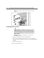
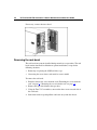
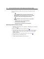
Extending the server from the rack
1. Release the two levers on the lower outside corners of the rack.
NOTE: If the server is in a rack and in the shipping configuration,
remove the two shipping screws directly behind the levers.
IMPORTANT: If the server is installed in a telco rack, remove the
server from the rack to access internal components.
Removal and replacement procedures
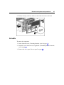
19
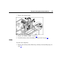
2. Extend the server on the rack rails until the server rail-release latches engage.
WARNING: To reduce the risk of personal injury or
equipment damage, be sure that the rack is adequately stabilized
before extending a component from the rack.
WARNING: To reduce the risk of personal injury, be
careful when pressing the server rail-release latches and sliding
the server into the rack. The sliding rails could pinch your fingers.
3. After performing the installation or maintenance procedure, slide the server
back into the rack by pressing the server rail release latches.
20
HP ProLiant ML570 Generation 3 Server Maintenance and Service Guide
NOTE: The release latches will lock into place when the rails are fully
extended.
Powering down the server
WARNING: To reduce the risk of personal injury, electric
shock, or damage to the equipment, remove the power cord to
remove power from the server. The front panel Power On/Standby
button does not completely shut off system power. Portions of the
power supply and some internal circuitry remain active until AC
power is removed.
IMPORTANT: If installing a hot-plug device, it is not necessary to
power down the server.
1. Shut down the OS as directed by the OS documentation.
2. Press the Power On/Standby button to place the server in standby mode.
When the server enters standby power mode, the system power LED changes
to amber.
3. Disconnect the power cords.
The system is now without power.
Removal and replacement procedures
21
Access panel
WARNING: To reduce the risk of personal injury from hot
surfaces, allow the drives and the internal system components to
cool before touching them.
CAUTION: Do not operate the server for long periods without
the access panel. Operating the server without the access panel results
in improper airflow and improper cooling that can lead to thermal
damage.
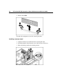
1. Extend the server from the rack, if applicable ("Extending the server from the
rack" on page 18).
2. Open the locking latch, slide the access panel to the rear of the chassis, and
remove the access panel.
NOTE: If the locking latch is locked, use a Torx T-15 screwdriver to
unlock the latch.
After installing hardware options, replace the access panel. Be sure that the panel
is securely locked into place before powering up the server.
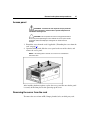
Removing the server from the rack
To remove the server from an HP, Compaq branded, telco, or third-party rack:
22
HP ProLiant ML570 Generation 3 Server Maintenance and Service Guide
1. Power down the server ("Powering down the server" on page 20).
2. Extend the server from the rack ("Extending the server from the rack" on
page 18).
3. Disconnect the cabling and remove the server from the rack. For more
information, refer to the documentation that ships with the rack mounting
option.
4. Place the server on a sturdy, level surface.
Removal and replacement procedures
23
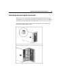
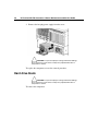
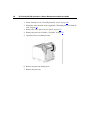
Unlocking and removing the tower bezel
Tower servers have a bezel that must be unlocked and opened before accessing
the hard drive cage, diskette drive, DVD drive, and the power switch. In addition,
the bezel is also removable when converting from a tower server to a rack server.
To unlock the tower bezel, use the key provided with the server to unlock the
bezel with a counterclockwise turn.
24
HP ProLiant ML570 Generation 3 Server Maintenance and Service Guide
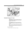
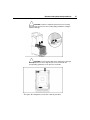
If necessary, remove the tower bezel.
Removing the rack bezel
The rack bezel must remain installed during normal server operations. The rack
bezel remains installed for all hardware options installations, except for the
following situations:
•
Removing or replacing the SCSI hard drive cage
•
Converting the server from a rack model to a tower model
To remove the rack bezel:
1. Extend or remove the server from the rack ("Extending the server from the
rack" on page 18, "Removing the server from the rack" on page 21).
2. Remove the tape drive blank or the tape drive.
3. Using the Torx T-15 screwdriver, unscrew the three screws on each side of
the rack bezel.
4. Push down on the snap and pull the rack bezel away from the chassis.
Removal and replacement procedures
25
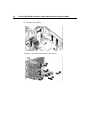
5. Release the snap at the base of the rack bezel and remove the rack bezel.
Air baffle
To remove the component:
1. Power down the server ("Powering down the server" on page 20).
2. Extend the server from the rack, if applicable ("Extending the server from the
rack" on page 18).
3. Remove the access panel ("Access panel" on page 21).
26
HP ProLiant ML570 Generation 3 Server Maintenance and Service Guide
4. Remove the processor air baffle.
To replace the component, reverse the removal procedure.
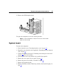
Center wall
To remove the component:
1. Power down the server ("Powering down the server" on page 20).
2. Unlock and open the front bezel ("Unlocking and removing the tower bezel"
on page 23) (tower servers only).
3. Extend or remove the server from the rack ("Extending the server from the
rack" on page 18, "Removing the server from the rack" on page 21).
4. Remove the access panel ("Access panel" on page 21).
5. Remove all expansion boards.
6. Lift the three latches and loosen the thumbscrew that secures the center wall
to the chassis.
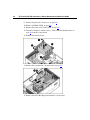
Removal and replacement procedures
7. Remove the center wall from the server.
To replace the component, reverse the removal procedure.
Redundant hot-plug power supply
WARNING: To reduce the risk of electric shock, do not
disassemble the power supply or attempt to repair it. Replace it
only with the specified spare part.
CAUTION: If only one power supply is installed, do not
remove the power supply unless the server has been powered down.
Removing the only operational power supply will cause an immediate
power loss.
NOTE: If you remove or replace the primary hot-plug power supply, use
the T-15 Torx screwdriver provided with the server to remove the
shipping screw. It is located just under the port-colored plastic handle of
the power supply unit.
To remove the component:
1. Disconnect the power cord from the power supply.
27
28
HP ProLiant ML570 Generation 3 Server Maintenance and Service Guide
2. Remove the hot-plug power supply from the server.
CAUTION: To prevent improper cooling and thermal damage,
do not operate the server unless all bays are populated with either a
component or a blank.
To replace the component, reverse the removal procedure.
Hard drive blank
CAUTION: To prevent improper cooling and thermal damage,
do not operate the server unless all bays are populated with either a
component or a blank.
To remove the component:
Removal and replacement procedures
29
1. Remove the hard drive blank.
To replace the component, reverse the removal procedure.
Hot-plug hard drives
CAUTION: Always power down the server if the boot partition
resides on the drive you are replacing or if you are replacing the only
drive in the server.
CAUTION: To prevent improper cooling and thermal damage,
do not operate the server unless all bays are populated with either a
component or a blank.
To remove the component:
1. Determine the status of the hard drive from the hot-plug hard drive LEDs
("Hot-plug SCSI hard drive LED combinations" on page 92, "Hot-plug SCSI
hard drive LEDs" on page 91).
2. Back up all server data contained on the hard drive.
30
HP ProLiant ML570 Generation 3 Server Maintenance and Service Guide
3. Remove the hard drive.
To replace the component, reverse the removal procedure.
Diskette drive blank
To remove the component:
1. Power down the server ("Powering down the server" on page 20).
2. Press the ejector button.
Removal and replacement procedures
3. Remove the diskette drive blank.
To replace the component, reverse the removal procedure.
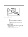
Diskette drive
To remove the component:
1. Power down the server ("Powering down the server" on page 20).
2. Press the ejector button.
31
32
HP ProLiant ML570 Generation 3 Server Maintenance and Service Guide
3. Remove the diskette drive from the server.
To replace the component, reverse the removal procedure.
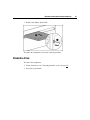
Optical device
To remove the component:
1. Power down the server ("Powering down the server" on page 20).
IMPORTANT: The ejector button is recessed to prevent accidental
ejection; it may be helpful to use a pen or similar shaped object to
access the button.
2. Press the ejector button.
Removal and replacement procedures
33
3. Remove the optical device.
To replace the drive, slide the drive into the bay until it clicks.
Hot-plug fans
IMPORTANT: Remove and replace one fan at a time. If the system
detects two fan failures while in full redundant mode, the server will shut
down to avoid thermal damage.
When all redundant fans are installed, individual fans can be hot-swapped at any
time. To remove the component:
1. Extend the server from the rack, if applicable ("Extending the server from the
rack" on page 18).
2. Remove the access panel ("Access panel" on page 21).
34
HP ProLiant ML570 Generation 3 Server Maintenance and Service Guide
3. Remove the hot-plug fan.
To replace the component, reverse the removal procedure.
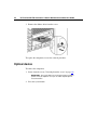
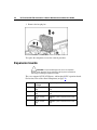
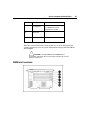
Expansion boards
CAUTION: To prevent damage to the server or expansion
boards, power down the server and remove all AC power cords before
removing or installing the expansion boards.
The server supports PCI-X, PCI Express, and hot-plug PCI-X expansion boards.
For location, refer to Rear Panel Components (on page 79).
Slot
Expansion
card type
Capable speed
1
PCI-X, non-hotplug
100 MHz* (slots 1 and 2 share the same
bus)
2
PCI-X, non-hotplug
100 MHz* (slots 1 and 2 share the same
bus)
3
PCI-X, non-hotplug
100 MHz* (slots 3 and 4 share the same
bus)
4
PCI-X, non-hotplug
100 MHz* (slots 3 and 4 share the same
bus)
Removal and replacement procedures
Slot
Expansion
card type
Capable speed
5
PCI Express
x4
6
PCI Express
x4
7
PCI Express
x4
8
PCI Express
x4
9
Hot-plug PCI-X
133 MHz
10
Hot-plug PCI-X
133 MHz
35
*HP recommends that cards with speeds of at least 100 MHz be installed in these
slots. If cards with lower bus speeds are installed, the bus speed will be reduced.
However, server performance will not suffer if the speed on one bus is slower
than the speed on a different bus.
To remove the component:
1. Power down the server ("Powering down the server" on page 20).
2. Extend or remove the server from the rack ("Extending the server from the
rack" on page 18, "Removing the server from the rack" on page 21).
3. Remove the access panel ("Access panel" on page 21).
4. Disconnect any required internal or external cables from the expansion
board.
36
HP ProLiant ML570 Generation 3 Server Maintenance and Service Guide
5. Release the retaining clip.
6. Remove the expansion board.
To replace the component, reverse the removal procedure.
Removal and replacement procedures
37
Memory options
This server supports up to four memory boards. Each memory board contains six
DIMM slots for a total of 24 DIMM slots in the server. Memory can be expanded
by installing PC2-3200R Registered DDR2 DRAM DIMMs.
The server supports a host of AMP options to optimize server availability:
•
Advanced ECC (hot-add enabled)
•
Advanced ECC (hot-add disabled)
•
Online Spare Memory (on page 40)
•
Hot-Plug Mirrored Memory (dual- and quad-board) ("Hot-plug mirrored
memory" on page 42)
•
Hot-Plug RAID Memory (on page 44)
Hot-plug operations can be hot-add or hot-replace. Hot-add makes additional
memory resources available to the OS. Hot-replace allows failed or degraded
DIMMs to be replaced while the server is running.
The maximum supported memory per memory board is 16 GB using four 4-GB
dual-rank DIMMs. Although six DIMM slots exist per board, the system
architecture allows a maximum of only four dual-rank DIMMs per memory
board to optimize performance.
For an overview of single- and dual-rank DIMMs, refer to "Single- and DualRank DIMMs."
For DIMM slot locations and bank assignments, refer to "DIMM Slots ("DIMM
slot locations" on page 85)."
General memory configuration requirements
The following configuration requirements apply regardless of the AMP mode.
•
DIMMs must be installed in pairs.
•
DIMM pairs in a memory bank must contain DIMMs with the same part
number.
38
HP ProLiant ML570 Generation 3 Server Maintenance and Service Guide
•
Always populate the memory boards in sequential order: Board 1, Board 2,
Board 3, and Board 4. Any deviation from this requirement results in the
server booting in Advanced ECC mode and Advanced ECC guidelines apply.
•
Always populate the DIMMs in sequential order per bank: Bank A, Bank B,
and Bank C.
•
Dual-rank DIMMs must be populated before single-rank DIMMs (see table).
•
If dual-rank DIMMs are installed in Bank A and Bank B, no additional
DIMMs may be installed in Bank C.
•
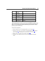
The following table lists all seven valid combinations of single- and dualrank DIMM configurations for a memory board. "Single" indicates a bank of
single-rank DIMMs. "Dual" indicates a bank of dual-rank DIMMs.
NOTE: A bank contains 2 DIMMs.
Configuration
Bank A
Bank B
1
Single
2
Single
Single
3
Single
Single
4
Dual
5
Dual
Single
6
Dual
Single
7
Dual
Dual
Bank C
Single
Single
•
The system can be configured for any AMP mode in RBSU. RBSU displays
a warning message if the selected AMP mode is not supported by the current
configuration. However, if the DIMM configuration at POST does not meet
the requirements for the AMP mode selected in RBSU, the server defaults to
Advanced ECC. The system indicates this by displaying a message during
POST and the status LED for the configured AMP mode flashes amber.
•
Unpopulated memory boards (those without any installed DIMMs) can be
installed in the server for storing extra memory boards.
•
If the server contains more than 4 GB of memory, consult the OS
documentation about accessing the full amount of installed memory.
Removal and replacement procedures
39
Configuring the memory
Configuring the memory system of the server requires configuring both hardware
and software.
To configure the memory:
1. Install the correct amount of memory for the desired AMP mode. For a list of
AMP options, refer to "Memory Options (on page 37)." For more
information, refer to "General Memory Configuration Requirements."
2. Test the DIMMs for all AMP modes, except Advanced ECC, before
configuring the AMP mode in RBSU. The two testing methods are:
−
POST memory test
−
ROM-Based Diagnostics test
NOTE: If the total amount of memory has changed, the POST Memory
Test will run automatically. Additional memory testing is not necessary.
3. Select the AMP mode.
Advanced ECC Memory
Advanced ECC Memory is the default memory protection mode for this server.
In Advanced ECC, the server is protected against correctable memory errors. The
server provides notification if the level of correctable errors exceeds a predefined threshold rate. The server does not fail because of correctable memory
errors. Advanced ECC provides additional protection over Standard ECC in that
it is possible to correct certain memory errors that would otherwise be
uncorrectable and result in a server failure. Whereas Standard ECC can correct
single-bit memory errors, Advanced ECC can correct single-bit memory errors
and multi-bit memory errors if all failed bits are on the same DRAM device on
the DIMM.
The following guidelines apply to Advanced ECC Memory:
•
All general memory requirements apply.
•
Advanced ECC mode is supported with 1, 2, 3, or 4 memory boards.
•
Hot-add is always enabled for Advanced ECC.
40
HP ProLiant ML570 Generation 3 Server Maintenance and Service Guide
•
Board insertions do not convert the AMP mode while the server is running.
A server cannot be converted from Advanced ECC to Online Spare Memory,
mirrored memory, or Hot-Plug RAID memory by inserting a board while the
server is running. Board insertions in Advanced ECC are solely for making
additional memory resources available to the OS.
•
Advanced ECC is the only mode in which hot-add operations are supported.
This is the only mode in which the amount of memory available to the OS
can be increased without a reboot.
•
Hot-add is performed by adding a memory board while the server is running,
and the additional memory is made available to the OS without a reboot. The
following rules apply to hot-add operations:
•
−
Boards must be inserted sequentially.
−
Multiple hot-add board insertions can be performed on the same server.
For example, if a server has three empty memory board slots, three hotadd board insertions can be performed.
−
If multiple hot-add operations are performed, allow one board insertion
operation to complete (as indicated by the memory board LEDs and OS
logs) before inserting another memory board.
If a memory board (which contains DIMMs) is unlocked while in Advanced
ECC mode, audio alarms and visual alerts occur.
CAUTION: When the memory board locking switch is
unlocked in a mode that does not support hot-add or hot-replace
capabilities, audio alarms and visual alerts occur. Removing the
memory board at this point causes server failure.
To end the audio alarms and visual alerts, move the memory board
locking switch back to the locked position. This action does not result in
data corruption or server failure.
If removal of a single memory board is required and it is the only
memory board, power down the server and make the necessary
memory changes.
Online spare memory
Online Spare Memory provides a higher level of memory protection than
Advanced ECC. With Online Spare Memory, the probability of a server failing
because of uncorrectable memory errors is reduced.
Removal and replacement procedures
41
In this mode, memory that is receiving a high rate of correctable memory errors
is automatically disengaged and a replacement set of memory is used in its place.
Since DIMMs that are receiving a high rate of correctable memory errors have an
increased probability of receiving an uncorrectable memory error (which results
in a server failure), the server experiences higher availability. The degraded
memory can be replaced during scheduled downtime and poses no additional risk
to the server.
Online Spare Memory is supported with one to four memory boards installed. On
this server, each installed memory board is protected by its own spare memory.
No OS support is required.
The following guidelines apply to Online Spare Memory:
•
All general memory requirements apply.
•
Online Spare Memory is supported with 1, 2, 3, or 4 memory boards.
•
Each board must have a valid Online Spare configuration. No dependencies
exist for the configuration between different memory boards.
•
Each memory board includes its own Online Spare Bank. All boards operate
independently in Online Spare mode. Each board can failover to its Online
Spare Bank independent of the other memory boards. Some boards can be in
Online Spare degraded mode while others are still in operational Online
Spare mode.
•
The minimum valid Online Spare configuration for a memory board requires
at least one bank of dual-rank DIMMs or two banks of single-rank DIMMs.
If the server does not meet these requirements, an error message is displayed
during POST and the server defaults to Advanced ECC and Advanced ECC
guidelines apply.
•
The server automatically configures the optimal Online Spare solution.
•
Online Spare Memory does not support any hot-plug operations.
HP recommends the following configurations. These configurations result in
optimal use of memory. Other configurations are valid, but do not result in the
maximum amount of installed memory being available to the OS.
•
If only single-rank DIMMs are used on a memory board, all DIMMs should
be of the same size on that memory board.
42
HP ProLiant ML570 Generation 3 Server Maintenance and Service Guide
•
If only dual-rank DIMMs are used on a memory board, all DIMMs should be
of the same size on that memory board.
•
If a mixture of single- and dual-rank DIMMs are used on a memory board,
the dual-rank DIMMs should be two times the size of any single-rank
DIMM.
After installing DIMMs, use RBSU to configure the system for online spare
memory support.
Hot-plug mirrored memory
Hot-Plug mirrored memory (mirrored memory) provides a higher level of
memory protection than either Advanced ECC or Online Spare Memory. With
mirrored memory, the server is protected against uncorrectable memory errors
that would otherwise result in server failure. Mirrored memory allows the server
to keep two copies of all memory data on separate memory boards.
If an uncorrectable error is encountered, the proper data is retrieved from the
memory board that does not contain the error. In addition, mirrored memory
allows failed or degraded DIMMs to be replaced while the server is running
without requiring server downtime. The memory board with the failed DIMM(s)
can be removed, failed DIMMs replaced, and the board re-inserted into the server
without any interruption to the OS.
Mirrored memory is supported with either two or four memory boards installed.
No OS support is required.
Mirrored memory has two configurations: dual-board and quad-board. Singleboard mirrored memory is not supported. For either mode, choose "Mirrored" in
RBSU.
The following guidelines apply to mirrored memory:
•
All general memory requirements apply.
•
Mirrored memory is supported with two or four memory boards.
Removal and replacement procedures
43
•
Memory boards 1 and 2 are populated for dual-board mirrored memory.
Boards 1, 2, 3, and 4 are populated for quad-board mirrored memory. Any
deviation from these guidelines results in the server booting in Advanced
ECC mode and Advanced ECC guidelines apply.
•
Memory boards 1 and 2 form a mirrored pair for dual-board mirrored
memory. For quad-board mirrored memory, memory boards 3 and 4 form an
additional mirrored pair.
•
Memory boards within a mirrored pair must have the same amount of total
memory. However, each board of the mirrored pair may have different
DIMM configurations as long as they have equal total size. For example,
memory boards 1 and 2 could each contain 2 GB of physical memory per
board with board 1 containing two 1-GB DIMMs and board 2 containing
four 512-MB DIMMs.
•
The amount of memory between mirrored pairs can be different in quadboard mirrored memory mode. For example, memory pair 1 (boards 1 and 2)
can contain 2 GB each while memory pair 2 (boards 3 and 4) contain 4 GB
each.
•
In quad-board mirrored memory, the two pairs of memory boards operate
independently. One of the pairs of memory boards can be degraded while the
other pair of memory boards can still be fully mirrored.
•
Hot-add operations are not permitted. Board removals and insertions in
mirrored memory are solely for the purpose of hot-replace operations.
•
For hot-replace to function properly, the memory board must be re-inserted
into the location from which it was removed. If the board is placed into the
incorrect slot (for example, if board 2 is removed in dual-board mirroring
mode and re-inserted into memory slots 3 or 4), a configuration error occurs.
Attempting to insert a board into the improper position results in audio
alarms and visual alerts.
•
Replace only one board at a time. That is, if memory boards 2 and 4 both
contain memory errors, remove board 2, replace the failed DIMMs, and
replace board 2 before proceeding to board 4.
•
If a board is inserted into a valid memory slot but with an invalid DIMM
configuration (including too much or too little memory), a DIMM
configuration error occurs and a visual alert occurs. Refer to Memory Board
LEDs ("Memory board LEDs and components" on page 93).
44
HP ProLiant ML570 Generation 3 Server Maintenance and Service Guide
•
If you remove a board while the server is running and do not replace the
board, the next reboot results in the system defaulting to Advanced ECC and
Advanced ECC guidelines apply.
Hot-plug RAID memory
Hot-plug RAID memory (RAID memory) provides a similar level of memory
protection as mirrored memory but obtains this protection using less total
memory. For example, in a RAID memory configuration, 25% of the installed
memory is not available to the OS. In a mirrored memory configuration,
however, 50% of the installed memory is not available to the OS. RAID memory
protects the server against uncorrectable memory errors that would otherwise
result in a server failure.
Although mirrored memory keeps two copies of all memory data, RAID memory
keeps only one copy of all memory data and additional parity information. If an
uncorrectable memory error is encountered, the server can create the proper data
using the parity information and the information from the other memory boards
that contain no failures.
As with mirrored memory, RAID memory allows failed or degraded DIMMs to
be replaced while the server is running without requiring server downtime. The
memory board with the failed DIMM(s) can be removed, failed DIMMs
replaced, and the board re-inserted into the server without any interruption to the
OS.
RAID memory is only supported if all four memory boards are installed. No OS
support is required.
The following guidelines apply to Hot-Plug RAID memory:
•
All general memory requirements apply.
•
RAID memory is only supported with four memory boards.
•
All four memory boards must have the same amount of total memory.
However, each board may have different DIMM configurations as long as
they have equal total size. Any deviation from this rule results in the server
booting in Advanced ECC mode and Advanced ECC guidelines apply.
•
No hot-add operations are supported in RAID memory, only hot-replace.
Removal and replacement procedures
•
45
If you remove a board while the server is running and do not replace it, the
next reboot results in the system reverting to Advanced ECC and Advanced
ECC guidelines apply.
Memory boards and DIMMs
Memory board and DIMM installation, removal, and replacement procedures can
be either hot-plug or non-hot-plug, depending on how the server is configured.
Hot-plug operations can be hot-add or hot-replace. Hot-add makes additional
memory resources available to the OS. Hot-replace allows failed or degraded
DIMMs to be replaced while the server is running. Hot-add is only supported
with Microsoft® Windows® 2003 or later. Hot-replace has no OS requirements.
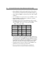
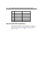
The following table illustrates AMP modes that support hot-plug features.
Advanced Memory
Protection Mode
HotReplace
Supported
Advanced ECC
Hot-Add
Supported
X
Online Spare Memory
Hot-Plug Mirrored Memory
X
Hot-Plug RAID Memory
X
When the server is configured for mirrored or RAID memory, you can perform a
hot-replacement procedure in the following manner without powering down the
server or experiencing server downtime:
1. Remove a memory board.
2. Replace failed or degraded DIMM(s).
3. Reinstall the memory board in the slot from which it was removed.
The replacement procedures in this section apply to both hot-plug and non-hotplug memory procedures, except as noted.
IMPORTANT: Be sure to power down the server when performing
board removal procedures in a server that is not configured for Mirrored
or Hot-Plug RAID Memory.
46
HP ProLiant ML570 Generation 3 Server Maintenance and Service Guide
Observe the following warnings when performing a hot-plug replacement
procedure.
WARNING: Always comply with all electrostatic and
thermal guidelines to prevent bodily injury and ensure a properly
functioning system when performing hot-plug operations.
WARNING: To prevent personal injury from hazardous
energy:
•
Remove watches, rings, or other metal objects.
•
Use tools with insulated handles.
•
Do not place tools or metal parts on top of batteries.
Removing a memory board (non-hot-plug)
1. Extend the server from the rack, if applicable ("Extending the server from the
rack" on page 18).
2. Remove the access panel ("Access panel" on page 21).
3. Determine which memory board is to be removed by locating the memory
board that displays an amber Board Status LED. Take note of the failed
DIMM, if applicable.
4. Power down the server ("Powering down the server" on page 20).
5. Unlock the memory board locking switch.
6. Unlock and open the memory board ejector lever.
Removal and replacement procedures
47
7. Remove the memory board.
8. Replace the DIMM ("DIMMs" on page 47).
9. Install the memory board ("Installing a memory board" on page 48).
DIMMs
To remove the component:
1. Remove the memory board ("Removing a memory board (non-hot-plug)" on
page 46).
48
HP ProLiant ML570 Generation 3 Server Maintenance and Service Guide
2. Remove the DIMM.
To replace the component, reverse the removal procedure.
Installing a memory board
1. Align the memory board with the memory board guide clips.
2. Install the memory board into the server and close the ejector lever.
3. Move the locking switch to the locked position.
Removal and replacement procedures
49
NOTE: In hot-plug procedures, all LEDs now turn off except the board
status LED, which flashes green while the board is rebuilding. This
process may take several minutes.
4. If this is a non-hot-plug procedure, power up the server and configure the
memory ("Configuring the memory" on page 39). If this is a hot-plug
procedure, proceed to step 5.
5. Observe the LEDs on the top of the memory board to be sure that the
memory is functioning properly ("Memory board LEDs and components" on
page 93). The LED states will be valid when the memory board has finished
rebuilding for hot-plug operations and when the server has completed
booting after a non-hot-plug operation.
6. Reinstall the access panel ("Access panel" on page 21).
Processor
The server supports up to four processors. With two or more processors installed,
the server supports boot functions through the processor installed in processor
socket 1. However, if processor 1 fails, the system attempts to boot from
processor 2 and provides a processor failure message.
CAUTION: To prevent thermal instability and damage to the
server, do not separate the processor from the heatsink. The processor,
heatsink, and retaining clip make up a single assembly.
CAUTION: To prevent possible server malfunction and
damage to the equipment, do not mix processors of different types.
IMPORTANT: If upgrading processor speed, update the system ROM
before installing the processor.
IMPORTANT: Processor socket 1 and PPM slot 1 must be populated
at all times or the server will not function properly.
IMPORTANT: Always install a PPM when you install a processor. The
system fails to boot if the PPM is missing.
IMPORTANT: To ensure proper cooling, be sure the processor baffle is
installed at all times.
To remove the component:
50
HP ProLiant ML570 Generation 3 Server Maintenance and Service Guide
1. Power down the server ("Powering down the server" on page 20).
2. Extend the server from the rack, if applicable ("Extending the server from the
rack" on page 18).
3. Remove the access panel ("Access panel" on page 21).
4. Remove the processor air baffle ("Air baffle" on page 25).
5. Open the processor retaining bracket.
6. Release the processor locking lever.
7. Remove the processor.
Removal and replacement procedures
CAUTION: Failure to completely open the processor locking
lever prevents the processor from seating during installation, leading to
hardware damage.
CAUTION: To prevent possible server malfunction or damage
to the equipment, be sure to align the pins on the socket with the
corresponding guide holes on the processor assembly.
To replace the component, reverse the removal procedure.
51
52
HP ProLiant ML570 Generation 3 Server Maintenance and Service Guide
PPM
The server PPMs provide the proper power to each processor. Each PPM must be
installed in the slot adjacent to its processor.
IMPORTANT: Processor socket 1 and PPM slot 1 must be populated
at all times or the server will not function properly.
IMPORTANT: Always install a PPM when you install a processor. The
system fails to boot if the PPM is missing.
IMPORTANT: To ensure proper cooling, be sure the processor baffle is
installed at all times.
To remove the component:
1. Power down the server ("Powering down the server" on page 20).
2. Extend the server from the rack, if applicable ("Extending the server from the
rack" on page 18).
3. Remove the access panel ("Access panel" on page 21).
4. Remove the processor air baffle ("Air baffle" on page 25).
5. Open the latches on the PPM retaining bracket and remove the PPM
retaining bracket.
Removal and replacement procedures
53
6. Remove the PPM.
IMPORTANT: Always install a PPM when you install a processor. The
system fails to boot if the corresponding PPM is missing.
To replace the component, reverse the removal procedure.
SCSI backplane board
To remove the component:
1. Power down the server ("Powering down the server" on page 20).
2. Extend the server from the rack, if applicable ("Extending the server from the
rack" on page 18).
3. Unlock and open the tower bezel ("Unlocking and removing the tower bezel"
on page 23) (tower servers only).
4. Remove the access panel ("Access panel" on page 21).
5. Remove the processor air baffle ("Air baffle" on page 25).
6. Remove the center wall ("Center wall" on page 26).
7. If the server is rack mounted, remove the rack bezel ("Removing the rack
bezel" on page 24).
8. Remove the media bezel.
54
HP ProLiant ML570 Generation 3 Server Maintenance and Service Guide
9. Disconnect all cabling.
10. Remove the SCSI cage from the server chassis.
Removal and replacement procedures
55
11. Remove the SCSI backplane board.
To replace the component, reverse the removal procedure.
NOTE: In some configurations, it may be necessary to route the SCSI
cables over the fan cage.
System board
To remove the component:
1. Power down the server ("Powering down the server" on page 20).
2. Extend the server from the rack, if applicable ("Extending the server from the
rack" on page 18).
3. Unlock and open the tower bezel ("Unlocking and removing the tower bezel"
on page 23) (tower servers only).
4. Place the chassis on its side with the access panel facing upwards.
5. Remove the access panel ("Access panel" on page 21).
6. Remove the processor air baffle ("Air baffle" on page 25).
7. Remove all expansion boards.
8. Remove all memory boards ("Removing a memory board (non-hot-plug)" on
page 46).
56
HP ProLiant ML570 Generation 3 Server Maintenance and Service Guide
9. Remove all processors ("Processor" on page 49).
10. Remove all PPMs ("PPM" on page 52).
11. Remove the center wall ("Center wall" on page 26).
12. Disconnect all power and data cables ("Cable connector identification" on
page 64) from the system board.
13. Remove the memory board.
14. Remove the system board ("System board" on page 55).
15. Remove the PCI-X Hot Plug basket from the system board.
Removal and replacement procedures
57
To replace the component, reverse the removal procedure.
Power backplane
To remove the component:
1. Remove the system board ("System board" on page 55).
2. Remove the power backplane.
To replace the component, reverse the removal procedure.
Tape drive blank
To remove the component:
1. Unlock and open the tower bezel ("Unlocking and removing the tower bezel"
on page 23) (tower servers only).
CAUTION: Always populate each media bay with either a
device or a blank. Proper airflow can only be maintained when the bays
are populated. Unpopulated drive bays can lead to improper cooling and
thermal damage.
58
HP ProLiant ML570 Generation 3 Server Maintenance and Service Guide
2. Pull the tape drive blank out of the chassis.
To replace the component, reverse the removal procedure.
Tape drive
To remove the component:
1. Unlock and open the tower bezel ("Unlocking and removing the tower bezel"
on page 23) (tower servers only).
Removal and replacement procedures
59
2. Slide the tape drive out of the server far enough to reach the cables.
3. Disconnect the data and power cables from the tape drive.
4. Remove the plastic guides from the tape drive:
a. Lift the plastic retainer from the slot closest to the front of the drive.
b. Repeat for the opposite plastic clip.
To replace the component, reverse the removal procedure.
Battery
If the server no longer automatically displays the correct date and time, you may
need to replace the battery that provides power to the real-time clock. Under
normal use, battery life is 5 to 10 years.
WARNING: The computer contains an internal lithium
manganese dioxide, a vanadium pentoxide, or an alkaline battery
pack. A risk of fire and burns exists if the battery pack is not
properly handled. To reduce the risk of personal injury:
60
HP ProLiant ML570 Generation 3 Server Maintenance and Service Guide
•
Do not attempt to recharge the battery.
•
Do not expose the battery to temperatures higher than
60°C (140°F).
•
Do not disassemble, crush, puncture, short external contacts,
or dispose of in fire or water.
•
Replace only with the spare designated for this product.
To locate the battery:
To remove the component:
1. Power down the server ("Powering down the server" on page 20).
2. Extend or remove the server from the rack ("Extending the server from the
rack" on page 18, "Removing the server from the rack" on page 21).
3. Remove the access panel ("Access panel" on page 21).
4. Remove the PPM holddown ("PPM" on page 52).
Removal and replacement procedures
61
5. Remove the battery.
To replace the component, reverse the removal procedure.
Run RBSU to configure the system after replacing the batter. Refer to the
HP ROM-Based Setup Utility User Guide for more detailed information.
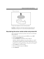
Re-entering the server serial number and product ID
After you replace the system board, you must re-enter the server serial number
and the product ID.
1. During the server startup sequence, press the F9 key to access RBSU.
2. Select the System Options menu.
3. Select Serial Number. The following warning is displayed:
WARNING! WARNING! WARNING! The serial number is loaded
into the system during the manufacturing process and
should NOT be modified. This option should only be used
by qualified service personnel. This value should always
match the serial number sticker located on the chassis.
4. Press the Enter key to clear the warning.
5. Enter the serial number and press the Enter key.
6. Select Product ID.
62
HP ProLiant ML570 Generation 3 Server Maintenance and Service Guide
7. Enter the product ID and press the Enter key.
8. Press the Esc key to close the menu.
9. Press the Esc key to exit RBSU.
10. Press the F10 key to confirm exiting RBSU. The server will automatically
reboot.
63
Server cabling
In this section
Storage device cabling guidelines ................................................................................................63
Cable connector identification......................................................................................................64
SCSI cabling .................................................................................................................................65
Tape drive cabling to the USB port ..............................................................................................67
RILOE II cabling ..........................................................................................................................67
Storage device cabling guidelines
CAUTION: To prevent damage to the equipment, be sure that
the server is powered down, all cables are disconnected from the back
of the server, and the power cord is disconnected from the grounded
(earthed) AC outlet before installing devices.
CAUTION: To prevent damage to electrical components,
properly ground the server before beginning any installation procedure.
Improper grounding can cause electrostatic discharge.
64
HP ProLiant ML570 Generation 3 Server Maintenance and Service Guide
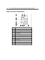
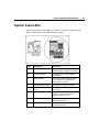
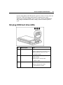
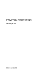
Cable connector identification
Item
Description
1
PCI Hot-Plug board
2
USB option
3
RILOE II
4
Fan board signal
5
Fan board signal
6
Fan board power
7
Power supply connectors
8
Fan connector
9
Fan connector
10
Power supply signal
11
SCSI 2
12
SCSI 1
Server cabling
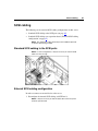
SCSI cabling
The following are the standard SCSI cabling configurations for this server:
•
Standard SCSI cabling to the SCSI ports (on page 65)
•
Standard SCSI cabling to an expansion board ("External SCSI cabling
configuration" on page 65)
NOTE: The appropriate cables should ship in the individual option kits
or with the device being installed.
Standard SCSI cabling to the SCSI ports
NOTE: In some configurations, it may be necessary to route the SCSI
cables over the fan cage.
External SCSI cabling configuration
In order to connect an external device to the server:
1. Reconfigure the internal SCSI cabling (to SCSI Port 2).
NOTE: It may be necessary to slide the SCSI cable service loop from
under the system board.
65
66
HP ProLiant ML570 Generation 3 Server Maintenance and Service Guide
NOTE: It may be necessary to run RBSU to assign boot order to SCSI
Port 2.
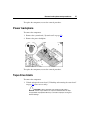
2. Connect the external device.
Server cabling
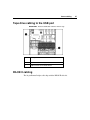
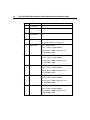
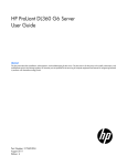
Tape drive cabling to the USB port
IMPORTANT: Route the USB cable under the mid fan cage.
Item
Description
1
USB connector on the system board
2
USB connector on the media device
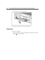
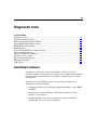
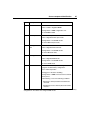
RILOE II cabling
The 30-pin Remote Insight cable ships with the RILOE II cable kit.
67
68
HP ProLiant ML570 Generation 3 Server Maintenance and Service Guide
IMPORTANT: Install the RILOE II board into slot 3 or 4 for ease of
cabling.
69
Diagnostic tools
In this section
SmartStart software ......................................................................................................................69
SmartStart Scripting Toolkit.........................................................................................................70
HP Instant Support Enterprise Edition .........................................................................................71
Option ROM Configuration for Arrays ........................................................................................71
HP ROM-Based Setup Utility ......................................................................................................72
ROMPaq utility ............................................................................................................................72
System Online ROM flash component utility ..............................................................................72
Integrated management log ..........................................................................................................73
Integrated Lights-Out technology.................................................................................................74
Automatic server recovery............................................................................................................74
HP Systems Insight Manager .......................................................................................................75
HP Insight Diagnostics .................................................................................................................75
USB support .................................................................................................................................76
SmartStart software
SmartStart is a collection of software that optimizes single-server setup,
providing a simple and consistent way to deploy server configuration. SmartStart
has been tested on many ProLiant server products, resulting in proven, reliable
configurations.
SmartStart assists the deployment process by performing a wide range of
configuration activities, including:
•
Configuring hardware using embedded configuration utilities, such as RBSU
and ORCA
•
Preparing the system for installing "off-the-shelf" versions of leading
operating system software
•
Installing optimized server drivers, management agents, and utilities
automatically with every assisted installation
70
HP ProLiant ML570 Generation 3 Server Maintenance and Service Guide
•
Testing server hardware using the Insight Diagnostics Utility ("HP Insight
Diagnostics" on page 75)
•
Installing software drivers directly from the CD. With systems that have
internet connection, the SmartStart Autorun Menu provides access to a
complete list of ProLiant system software.
•
Enabling access to the Array Configuration Utility, Array Diagnostic Utility,
and Erase Utility
SmartStart is included in the HP ProLiant Essentials Foundation Pack. For more
information about SmartStart software, refer to the HP ProLiant Essentials
Foundation Pack or the HP website (http://www.hp.com/servers/smartstart).
SmartStart Scripting Toolkit
The SmartStart Scripting Toolkit is a server deployment product that delivers an
unattended automated installation for high-volume server deployments. The
SmartStart Scripting Toolkit is designed to support ProLiant BL, ML, and DL
servers. The toolkit includes a modular set of utilities and important
documentation that describes how to apply these new tools to build an automated
server deployment process.
Using SmartStart technology, the Scripting Toolkit provides a flexible way to
create standard server configuration scripts. These scripts are used to automate
many of the manual steps in the server configuration process. This automated
server configuration process cuts time from each server deployed, making it
possible to scale server deployments to high volumes in rapid fashion.
For more information, and to download the SmartStart Scripting Toolkit, refer to
the HP website (http://www.hp.com/servers/sstoolkit).
Diagnostic tools
71
HP Instant Support Enterprise Edition
ISEE is a proactive remote monitoring and diagnostic tool to help manage your
systems and devices, a feature of HP support. ISEE provides continuous
hardware event monitoring and automated notification to identify and prevent
potential critical problems. Through remote diagnostic scripts and vital system
configuration information collected about your systems, ISEE enables fast
restoration of your systems. Install ISEE on your systems to help mitigate risk
and prevent potential critical problems.
For more information on ISEE, refer to the HP website
(http://www.hp.com/hps/hardware/hw_enterprise.html).
To download HP ISEE, visit the HP website
(http://www.hp.com/hps/hardware/hw_downloads.html).
For installation information, refer to the HP ISEE Client Installation and Upgrade
Guide (ftp://ftp.hp.com/pub/services/hardware/info/isee_client.pdf).
Option ROM Configuration for Arrays
Before installing an operating system, you can use the ORCA utility to create the
first logical drive, assign RAID levels, and establish online spare configurations.
The utility also provides support for the following functions:
•
Reconfiguring one or more logical drives
•
Viewing the current logical drive configuration
•
Deleting a logical drive configuration
If you do not use the utility, ORCA will default to the standard configuration.
For more information regarding array controller configuration, refer to the
controller user guide.
For more information regarding the default configurations that ORCA uses, refer
to the HP ROM-Based Setup Utility User Guide on the Documentation CD.
72
HP ProLiant ML570 Generation 3 Server Maintenance and Service Guide
HP ROM-Based Setup Utility
RBSU, an embedded configuration utility, performs a wide range of
configuration activities that may include:
•
Configuring system devices and installed options
•
Displaying system information
•
Selecting the primary boot controller
•
Configuring memory options
•
Language selection
For more information on RBSU, refer to the HP ROM-Based Setup Utility User
Guide on the Documentation CD or the HP website
(http://www.hp.com/servers/smartstart).
ROMPaq utility
Flash ROM enables you to upgrade the firmware (BIOS) with system or option
ROMPaq utilities. To upgrade the BIOS, insert a ROMPaq diskette into the
diskette drive and boot the system.
The ROMPaq utility checks the system and provides a choice (if more than one
exists) of available ROM revisions. This procedure is the same for both system
and option ROMPaq utilities.
For more information about the ROMPaq utility, refer to the HP website
(http://www.hp.com/servers/manage).
System Online ROM flash component utility
The Online ROM Flash Component Utility enables system administrators to
efficiently upgrade system or controller ROM images across a wide range of
servers and array controllers. This tool has the following features:
•
Works offline and online
Diagnostic tools
•
73
Supports Microsoft® Windows NT®, Windows® 2000, Windows® Server
2003, Novell Netware, and Linux operating systems
IMPORTANT: This utility supports operating systems that may not be
supported by the server. For operating systems supported by the
server, refer to the HP website (http://www.hp.com/go/supportos).
•
Integrates with other software maintenance, deployment, and operating
system tools
•
Automatically checks for hardware, firmware, and operating system
dependencies, and installs only the correct ROM upgrades required by each
target server
To download the tool and for more information, refer to the HP website
(http://h18000.www1.hp.com/support/files/index.html).
Integrated management log
The IML records hundreds of events and stores them in an easy-to-view form.
The IML timestamps each event with 1-minute granularity.
You can view recorded events in the IML in several ways, including the
following:
•
From within HP SIM
•
From within Survey Utility
•
From within operating system-specific IML viewers
•
−
For NetWare: IML Viewer
−
For Windows®: IML Viewer
−
For Linux: IML Viewer Application
From within HP Insight Diagnostics
For more information, refer to the Management CD in the HP ProLiant Essentials
Foundation Pack.
74
HP ProLiant ML570 Generation 3 Server Maintenance and Service Guide
Integrated Lights-Out technology
The iLO subsystem is a standard component of selected ProLiant servers that
provides server health and remote server manageability. The iLO subsystem
includes an intelligent microprocessor, secure memory, and a dedicated network
interface. This design makes iLO independent of the host server and its operating
system. The iLO subsystem provides remote access to any authorized network
client, sends alerts, and provides other server management functions.
Using iLO, you can:
•
Remotely power up, power down, or reboot the host server.
•
Send alerts from iLO regardless of the state of the host server.
•
Access advanced troubleshooting features through the iLO interface.
•
Diagnose iLO using HP SIM through a web browser and SNMP alerting.
For more information about iLO features, refer to the Integrated Lights-Out User
Guide on the Documentation CD or on the HP website
(http://www.hp.com/servers/lights-out).
Automatic server recovery
ASR is a feature that causes the system to restart when a catastrophic operating
system error occurs, such as a blue screen, ABEND, or panic. A system fail-safe
timer, the ASR timer, starts when the System Management driver, also known as
the Health Driver, is loaded. When the operating system is functioning properly,
the system periodically resets the timer. However, when the operating system
fails, the timer expires and restarts the server.
ASR increases server availability by restarting the server within a specified time
after a system hang or shutdown. At the same time, the HP SIM console notifies
you by sending a message to a designated pager number that ASR has restarted
the system. You can disable ASR from the HP SIM console or through RBSU.
Diagnostic tools
75
HP Systems Insight Manager
HP SIM is a web-based application that allows system administrators to
accomplish normal administrative tasks from any remote location, using a web
browser. HP SIM provides device management capabilities that consolidate and
integrate management data from HP and third-party devices.
IMPORTANT: You must install and use HP SIM to benefit from the PreFailure Warranty for processors, hard drives, and memory modules.
For additional information, refer to the Management CD in the HP ProLiant
Essentials Foundation Pack or the HP SIM website
(http://www.hp.com/go/hpsim).
HP Insight Diagnostics
HP Insight Diagnostics is a proactive server management tool, available in both
offline and online versions, that provides diagnostics and troubleshooting
capabilities to assist IT administrators who verify server installations,
troubleshoot problems, and perform repair validation.
HP Insight Diagnostics Offline Edition performs various in-depth system and
component testing while the OS is not running. To run this utility, launch the
SmartStart CD.
HP Insight Diagnostics Online Edition is a web-based application that captures
system configuration and other related data needed for effective server
management. Available in Microsoft® Windows® and Linux versions, the utility
helps to ensure proper system operation.
For more information or to download the utility, refer to the HP website
(http://www.hp.com/servers/diags).
76
HP ProLiant ML570 Generation 3 Server Maintenance and Service Guide
USB support
HP provides both standard USB support and legacy USB support. Standard
support is provided by the operating system through the appropriate USB device
drivers. HP provides support for USB devices before the operating system
loading through legacy USB support, which is enabled by default in the system
ROM. HP hardware supports USB version 1.1 or 2.0, depending on the version
of the hardware.
Legacy USB support provides USB functionality in environments where USB
support is normally not available. Specifically, HP provides legacy USB
functionality for:
•
POST
•
RBSU
•
Diagnostics
•
DOS
•
Operating environments which do not provide native USB support
For more information on ProLiant USB support, refer to the HP website
(http://h18004.www1.hp.com/products/servers/platforms/usb-support.html).
Internal USB functionality
An internal USB connector is available for use with USB backup tape drives.
The internal connector is not shared with any of the external USB connectors.
One internal USB device and up to three external devices can be supported at the
same time.
77
Server component identification
In this section
Front panel components................................................................................................................77
Front panel LEDs and buttons ......................................................................................................78
Rear panel components.................................................................................................................79
Rear panel LEDs and buttons .......................................................................................................81
System board components ............................................................................................................82
Internal health LED combinations................................................................................................86
System board LEDs ......................................................................................................................87
Hot-plug power supply LEDs.......................................................................................................89
SCSI IDs.......................................................................................................................................90
NMI jumper ..................................................................................................................................90
Hot-plug SCSI hard drive LEDs...................................................................................................91
Hot-plug SCSI hard drive LED combinations..............................................................................92
Memory board LEDs and components .........................................................................................93
Fan locations.................................................................................................................................97
Front panel components
78
HP ProLiant ML570 Generation 3 Server Maintenance and Service Guide
Item
Description
1
Diskette drive blank
2
DVD-ROM drive
3
USB port
4
Tape drive blank
5
SCSI channel 2 (channels 0 and 1)
6
SCSI channel 1 (channels 0-7)
Front panel LEDs and buttons
Item
Description
Status
1
UID switch and LED
Blue = Activated
Flashing blue = System being managed remotely
Off = Deactivated
2
Internal system health
LED
Green = Normal (system on)
Flashing Amber = System health is degraded
Flashing Red = System health is critical
Server component identification
Item
Description
Status
3
External system health
(power supply) LED
Green = Normal (system on)
Flashing Amber = Redundant power supply failure
Flashing Red = Power supply failure. No operational power
supplies.
4
NIC 1 link/activity LED
(embedded NIC only)
Green = Linked to network
Flashing green = Linked with activity on the network
Off = No network connection
5
NIC 2 link/activity LED
(embedded NIC)
Green = Linked to network
Flashing green = Linked with activity on the network
Off = No network connection
6
Power on/Standby button
and LED
Green = System has AC power and is powered on
Amber = System has AC power and is in standby mode
Off = System has no AC power
Rear panel components
79
80
HP ProLiant ML570 Generation 3 Server Maintenance and Service Guide
Item
Description
1
NIC 2
2
NIC 1
3
USB Ports
4
iLo
5
Parallel port
6
64-bit/100-MHz PCI-X slot 1
7
64-bit/100-MHz PCI-X slot 2
8
64-bit/100-MHz PCI-X slot 3
9
64-bit/100-MHz PCI-X slot 4
10
PCI Express x4 slot 5
11
PCI Express x4 slot 6
12
PCI Express x4 slot 7
13
PCI Express x4 slot 8
14
64-bit/133-MHz PCI-X hot-plug slot 9
15
64-bit/133-MHz PCI-X hot-plug slot 10
16
Power supply (primary)
17
Power supply blank
18
T-15 Torx screwdriver
19
External SCSI port
20
UID LED
21
Keyboard port
22
Mouse port
23
Video port
24
Serial port
Server component identification
Rear panel LEDs and buttons
Item
Description
LED Color
Status
1
Unit ID LED
Blue
On = Activated
Flashing = System remotely managed
Off = Deactivated
2
3
4
NIC Activity LED
(Integrated NC7782)
Green
NIC Link LED
(Integrated NC7782)
Green
iLO NIC Activity LED
Green
On or flashing = Linked to network
Off = Not linked to network
On = Network activity
Off = No network activity
On or flashing = Network activity
Off = No network activity
5
iLO NIC Link LED
Green
On = Linked to network
Off = Not linked to network
6
Power supply LED
(primary and redundant)
Green
Refer to Hot-plug Power Supply LEDs (on page
89)
7
Power supply LED
(primary and redundant)
Amber
Refer to Hot-plug Power Supply LEDs (on page
89)
81
82
HP ProLiant ML570 Generation 3 Server Maintenance and Service Guide
System board components
Item
Description
1
64-bit/133-MHz PCI-X Hot-Plug slot 10
2
64-bit/133-MHz PCI-X Hot-Plug slot 9
3
PCI Express x4 slot 8
4
PCI Express x4 slot 7
5
PCI Express x4 slot 6
6
PCI Express x4 slot 5
7
64-bit/100-MHz PCI-X slot 4
8
64-bit/100-MHz PCI-X slot 3
9
64-bit/100-MHz PCI-X slot 2
10
64-bit/100-MHz PCI-X slot 1
11
Memory board slot 1
12
Memory board slot 2
13
Memory board slot 3
14
Memory board slot 4
15
PPM slot 1
Server component identification
Item
Description
16
PPM slot 2
17
QuickFind diagnostic display
18
System maintenance switch (SW-2)
19
Miscellaneous switch (SW-1)
20
PPM slot 4
21
NMI jumper
22
PPM slot 3
23
Processor socket 4
24
Fan board signal connector
25
Processor socket 3
26
Processor socket 2
27
Fan board signal connector
28
Fan board power connector
29
Processor socket 1
30
Power connector
31
RILOE II connector
32
Power connector
33
Fan connector
34
Fan connector
35
Power supply signal connector
36
USB option connector
37
SCSI connector 2
38
SCSI connector 1
39
PCI hot-plug board connector
83
84
HP ProLiant ML570 Generation 3 Server Maintenance and Service Guide
System maintenance switches
The system miscellaneous switch (SW1) is an eight-position switch that is
reserved. The default position for all eight positions is Off.
Position
Description
1
Reserved
2
Reserved
3
Reserved
4
Reserved
5
Reserved
6
Reserved
7
Reserved
8
Reserved
Function
The system maintenance switch (SW2) is an eight-position switch that is used for
system configuration. The default position for all eight positions is Off.
Position
Description
Function
S1
iLO Security
Off = iLO security is enabled
On = iLO security is disabled
S2
Configuration
lock
Off = System configuration can
be changed
On = System configuration is
locked
S3
Reserved
Reserved
S4
Reserved
Reserved
S5
Password
protection
override
Off = No function
On = Clears power-on
password and administrator
password
Server component identification
Position
Description
Function
S6
Invalid
configuration
Off = Normal
S7
Reserved
S8
Reserved
On = ROM treats system
configuration as invalid
When the system maintenance switch position 6 is set to the On position, the
system is prepared to erase all system configuration settings from both CMOS
and NVRAM.
CAUTION: Clearing CMOS and/or NVRAM deletes
configuration information. Be sure to properly configure the server or
data loss could occur.
DIMM slot locations
85
86
HP ProLiant ML570 Generation 3 Server Maintenance and Service Guide
DIMM
Slot
Description
Bank
1
PC2-3200R DIMM slot
Bank A
2
PC2-3200R DIMM slot
Bank A
3
PC2-3200R DIMM slot
Bank B
4
PC2-3200R DIMM slot
Bank B
5
PC2-3200R DIMM slot
Bank C
6
PC2-3200R DIMM slot
Bank C
Internal health LED combinations
When the internal health LED on the front panel illuminates either flashing
amber or flashing red, the server is experiencing a health event. Combinations of
illuminated system board LEDs (on page 87) and the internal health LED
indicate system status.
Server component identification
System board LEDs
In normal operations, all the LEDs are off unless one of the components fails.
When a component fails, the LED illuminates amber.
Code
Component
Explanation
01
Power supply cable(s)
System board to power supply cables:
defective cables or cables not installed
04
Fan board cable(s)
Fan board power or signal cables are
not installed.
05
Memory board
Base memory failure (memory board 1
is not installed or no valid memory
configuration is present)
06
SCSI board power cable
SCSI board or cable is not present
07
PCI hot-plug switch
board
PCI Hot Plug switch board or cable is
not present.
08
System interlock
Main system interlock catch-all.
Indicates an interlock problem not
flagged by codes 01 to 07.
f1
Processor 1 unsupported
Processor 1 unsupported. Replace with
a supported processor.
t2
Processor 2 unsupported
Processor 2 unsupported. Replace with
a supported processor.
87
88
HP ProLiant ML570 Generation 3 Server Maintenance and Service Guide
Code
Component
Explanation
t3
Processor 3 unsupported
Processor 3 unsupported. Replace with
a supported processor.
t4
Processor 4 unsupported
Processor 4 unsupported. Replace with
a supported processor.
P1
Processor 1 is missing
Processor 1 is missing, and is required
to boot. Install Processor 1. If
processor 4 is installed and the system
is booting up, the P1 code and Port
84/85 will be displayed one second
each to show the unit is booting.
U1
PPM1 is missing
Processor 1 is installed without PPM 1.
Install PPM 1.
U2
PPM2 is missing
Processor 2 is installed without PPM 2.
Install PPM 2.
U3
PPM3 is missing
Processor 3 is installed without PPM 3.
Install PPM 3.
U4
PPM4 is missing
Processor 4 is installed without PPM 4.
Install PPM 4.
A0
Pre POST code
Standby mode
P5
Power supply
No power from the power supply
_5
Power backplane
No 5-V power from the power supply
backplane board
33
Power backplane
No 3.3-V power from the power supply
backplane board
15
1.5V Regulator
No 1.5-V power from the voltage
regulator on the system board
Ut
VTT Regulator
No power from the VTT voltage
regulator on the system
5U
PPM Failure
No power from the PPM
nb
No boot
Indicates a no-boot situation
Server component identification
Hot-plug power supply LEDs
Item
Description
1
Primary power supply power LED (green)
2
Primary power supply fail LED (amber)
3
Redundant power supply power LED (green)
4
Redundant power supply fail LED (amber)
Power Supply Condition
Power LED
(Green)
Fail LED
(Amber)
No AC power to all power supply
units
Off
Off
No AC power to this power
supply unit only or power supply
failure (includes over voltage
and over temperature)
Off
On
AC present/Standby outputs on
Flashing
Off
Power supply DC outputs On
and OK
On
Off
Power supply failure (current
limit)
Off
Flashing
89
90
HP ProLiant ML570 Generation 3 Server Maintenance and Service Guide
SCSI IDs
The server supports two simplex SCSI channels.
•
Channel 1 supports up to eight drives (channels 0 to 7).
•
Channel 2 supports up to two drives (channels 0 to 1).
The SCSI IDs for both channel configurations are illustrated. HP recommends
populating hard drive bays starting with the lowest SCSI ID.
NOTE: These SCSI ID designations apply regardless of the controller
or the configuration used.
NMI jumper
The NMI jumper allows administrators to perform a memory dump before
performing a hard reset. Crash dump analysis is an essential part of eliminating
reliability problems, such as hangs or crashes in OSs, device drivers, and
applications. Many crashes can freeze a system, requiring you to do a hard reset.
Resetting the system erases any information that would support root cause
analysis.
Server component identification
91
Systems running Microsoft® Windows® experience a blue-screen trap when the
OS crashes. When this happens, Microsoft® recommends that system
administrators perform an NMI event by temporarily shorting the NMI header
with a jumper. The NMI event enables a hung system to become responsive
again.
Hot-plug SCSI hard drive LEDs
Item
LED Description
Status
1
Activity status
On = Drive activity
Flashing = High activity on the drive or drive
is being configured as part of an array.
Off = No drive activity
2
Online status
On = Drive is part of an array and is
currently working.
Flashing = Drive is actively online.
Off = Drive is offline.
3
Fault status
On = Drive failure
Flashing = Fault-process activity
Off = No fault-process activity
92
HP ProLiant ML570 Generation 3 Server Maintenance and Service Guide
Hot-plug SCSI hard drive LED combinations
Activity
LED (1)
Online
LED (2)
Fault LED Interpretation
(3)
On, off, or
flashing
On or off
Flashing
On, off, or
flashing
On
On or
flashing
Flashing
A predictive failure alert has been received for this drive.
Replace the drive as soon as possible.
Off
The drive is online and is configured as part of an array.
If the array is configured for fault tolerance and all other drives in the
array are online, and a predictive failure alert is received or a drive
capacity upgrade is in progress, you may replace the drive online.
Off
Do not remove the drive. Removing a drive may terminate the
current operation and cause data loss.
The drive is rebuilding or undergoing capacity expansion.
On
Off
Off
Do not remove the drive.
The drive is being accessed, but (1) it is not configured as part of an
array; (2) it is a replacement drive and rebuild has not yet started; or
(3) it is spinning up during the POST sequence.
Flashing
Flashing
Flashing
Do not remove the drive. Removing a drive may cause data loss
in non-fault-tolerant configurations.
Either (1) the drive is part of an array being selected by an array
configuration utility; (2) Drive Identification has been selected in
HP SIM; or (3) drive firmware is being updated.
Off
Off
On
The drive has failed and has been placed offline.
You may replace the drive.
Off
Off
Off
Either (1) the drive is not configured as part of an array; (2) the drive
is configured as part of an array, but it is a replacement drive that is
not being accessed or being rebuilt yet; or (3) the drive is configured
as an online spare.
If the drive is connected to an array controller, you may replace the
drive online.
Server component identification
Memory board LEDs and components
Error indicators remain illuminated when the system is powered off so that the
status of the LEDs can still be seen. This matches the behavior of all the other
error indicators in the server.
Error indicators will only be cleared if:
•
The locking switch is locked after the board is reinstalled
•
The system has been rebooted
•
The board is removed from the system
CAUTION: When the memory board locking switch is
unlocked in a mode that does not support hot-add or hot-replace
capabilities, audio alarms and visual alerts occur. Removing the
memory board at this point causes server failure.
To end the audio alarms and visual alerts, move the memory board
locking switch back to the locked position. This action does not result in
data corruption or server failure.
If removal of a single memory board is required and it is the only
memory board, power down the server and make the necessary
memory changes.
93
94
HP ProLiant ML570 Generation 3 Server Maintenance and Service Guide
Item
Description
Status
1
Release Latch
N/A
2
Ejector Lever
N/A
3
Locking Switch
N/A
4
Removable
Green = OK to remove the board
Off = Do not remove if the system is on
5
DIMM 1 LED
Green = DIMM installed
Amber = Failed or degraded DIMM
Flashing amber = DIMM configuration error
Off = No DIMM installed
6
DIMM 2 LED
Green = DIMM installed
Amber = Failed or degraded DIMM
Flashing amber = DIMM configuration error
Off = No DIMM installed
7
DIMM 3 LED
Green = DIMM installed
Amber = Failed or degraded DIMM
Flashing amber = DIMM configuration error
Off = No DIMM installed
8
DIMM 4 LED
Green = DIMM installed
Amber = Failed or degraded DIMM
Flashing amber = DIMM configuration error
Off = No DIMM installed
9
DIMM 5 LED
Green = DIMM installed
Amber = Failed or degraded DIMM
Flashing amber = DIMM configuration error
Off = No DIMM installed
Server component identification
Item
Description
Status
10
DIMM 6 LED
Green = DIMM installed
95
Amber = Failed or degraded DIMM
Flashing amber = DIMM configuration error
Off = No DIMM installed
11
Online Spare LED Green = Online spare mode
Amber = Degraded online spare mode
Flashing amber = Invalid AMP mode*
Off = Not in Online Spare mode
12
Hot-Plug Mirrored
LED
Green = Mirrored mode
Amber = Degraded mirrored mode
Flashing amber = Invalid AMP mode*
Off = Not in Mirrored mode
13
Hot-Plug RAID LED Green = RAID mode
Amber = Degraded RAID mode
Flashing amber = Invalid AMP mode*
Off = Not in RAID mode
14
Board Status LED Off = Power off - memory board locking switch not
engaged or invalid memory configuration.
Green = Normal operation
Flashing green = Board is rebuilding
Flashing amber = DIMM on this board encountered
memory errors
Amber Flashing = one of the following conditions:
•
Unlocking a memory board that should not be
removed
•
Attempting to insert a memory board at runtime
that fails
*The following applies to an invalid AMP error. This error occurs when the current memory
configuration is not valid for the configured AMP mode:
96
HP ProLiant ML570 Generation 3 Server Maintenance and Service Guide
−
If the mode selected is the desired mode, modify the DIMM/board
configuration to support the desired mode. Refer to the memory
overview section.
−
If the mode selected is not the desired mode, run RBSU and change the
AMP mode. Refer to "HP ROM-Based Setup Utility ("HP ROM-Based
Setup Utility" on page 72)" for more information.
NOTE: If the Online Spare, Mirrored, and RAID LEDs are off, the
server is in Advanced ECC mode. Refer to "HP ROM-Based Setup
Utility (on page 72)" for more information.
The following table illustrates the different LED combinations for a correctly
configured memory board.
LED
Advanced
ECC Memory
Online
Spare
Memory
Hot-Plug
Mirrored
Memory
Hot-Plug RAID
Memory
Board status
Green
Green
Green
Green
DIMM 1 to
6, if
populated
Green
Green
Green
Green
Online
Spare status
Off
Green
Off
Off
Mirrored
status
Off
Off
Green
Off
RAID status
Off
Off
Off
Green
Board
Removable
Off
Off
Green
Green
Server component identification
Fan locations
Item
Description
Configuration
1
Fan 1
Redundant
2
Fan 2
Primary
3
Fan 3
Redundant
4
Fan 4
Primary
5
Fan 5
Redundant
6
Fan 6
Primary
97
99
Specifications
In this section
Server specifications.....................................................................................................................99
Environmental specifications .....................................................................................................100
Hot-plug power supply calculations ...........................................................................................100
DDR SDRAM DIMM specifications .........................................................................................100
1.44-MB diskette drive specifications ........................................................................................101
CD-ROM drive specifications ....................................................................................................102
DVD-ROM drive specifications .................................................................................................103
Ultra320 SCSI hard drive specifications ....................................................................................105
Server specifications
The following information pertains to the rack configuration.
Dimension
Specification
Height
26.67 cm (10.5 in)
Depth
67.31 cm (26.5 in)
Width
44.45 cm (17.5 in)
Weight (maximum)
63.5 kg (140 lb)
Weight (no drives installed)
41.28 kg (91 lb)
Input requirement
Specification
Rated input voltage
100-127 VAC
200 - 240 VAC
Rated input frequency
50 Hz - 60 Hz
Rated input current
@ 100VAC - 12 A
@ 200VAC - 8 A
Rated input power
@100 VAC - 1161 W
@200 VAC - 1598 W
BTUs per hour
@100 VAC - 3960
@200 VAC - 5450
100
HP ProLiant ML570 Generation 3 Server Maintenance and Service Guide
Power supply output
910 W (low line)
1300 W (high line)
Environmental specifications
Temperature range*
Specification
Operating
10°C to 35°C (50°F to 95°F)
Shipping
-40°C to 70°C (-40°F to 158°F)
Maximum wet bulb temperature 28°C (82.4°F)
Relative humidity
(noncondensing)**
Specification
Operating
10% to 90%
Non-operating
5% to 95%
* All temperature ratings shown are for sea level. An altitude derating of 1°C per 300 m
(1.8°F per 1,000 ft) to 3048 m (10,000 ft) is applicable. No direct sunlight allowed.
** Storage maximum humidity of 95% is based on a maximum temperature of 45°C
(113°F). Altitude maximum for storage corresponds to a pressure minimum of 70 KPa.
Hot-plug power supply calculations
For hot-plug power supply specifications and calculators to determine electrical
and heat loading for the server, refer to the HP Enterprise Configurator website
(http://h30099.www3.hp.com/configurator/).
DDR SDRAM DIMM specifications
NOTE: Use only 512-MB, 1-GB, 2-GB, or 4-GB; 72-bit wide; 2.5-V;
PC2-3200 Registered ECC DDR2 SDRAM. Use HP DDR2 SDRAM
only.
Item
Description
Size
512 MB, 1 GB, 2 GB, or 4 GB
Specifications
Item
Description
Width
72 bits
Upgrade requirement Any combination of like-paired DDR SDRAM DIMMs that
provide a minimum of 1 GB
1.44-MB diskette drive specifications
Item
Description
Dimensions
Height
12.7 mm (0.5 in)
Width
96 mm (3.8 in)
Depth
130 mm (5.1 in)
LEDs (front panel)
Green = On
Read/write capacity per
diskette
High density
1.44 MB
Low density
720 KB
Drives supported
1
Drive height
One-third height
Drive rotation
300 rpm
Transfer rate
High
500 Kb/s
Low
250 Kb/s
Bytes/sector
512
Sectors per track (high/low)
18/9
Tracks per side (high/low)
80/80
Access times
Track-to-track (high/low)
3 ms/6 ms
Average (high/low)
169 ms/94 ms
101
102
HP ProLiant ML570 Generation 3 Server Maintenance and Service Guide
Item
Description
Setting time
15 ms
Latency average
100 ms
Cylinders (high/low)
80/80
Read/write heads
2
CD-ROM drive specifications
Item
Description
Applicable disk
CD-ROM (modes 1 and 2); mixed mode (audio and data combined); CD-DA;
Photo CD (single/multiple-session), CD-XA ready; CDi ready
Capacity
550 MB (mode 1, 12 cm)
640 MB (mode 2, 12 cm)
Block size
2368, 2352 bytes (mode 0)
2352, 2340, 2336, 2048 bytes (mode 1)
2352, 2340, 2336, 2048 bytes (mode 2)
Dimensions
Height
12.7 mm (0.50 in)
Depth
132.08 mm (5.20 in)
Width
132.08 mm (5.20 in)
Weight
0.34 kg (0.75 lb)
Data transfer rate
Sustained
150 KB/s (sustained 1X), 1500/3600 KB/s (10X to 24X)
Burst
16.6 MB/s
Access times (typical)
Full stroke
300 ms
Random
140 ms
Diameter
12 cm, 8 cm (4.70 in, 3.15 in)
Thickness
1.2 mm (0.05 in)
Specifications
Item
Description
Track pitch
1.6 µm (6.3 × 10⁻⁷ in)
Cache/buffer
128 KB
Startup time
< 10 s
Stop time
< 5 s (single); < 30 s (multisession)
103
Laser parameters
Type
Semiconductor laser GaAs
Wave length
700 ± 25 nm
Divergence angle
53.5° ± 1.5°
Output power
0.14 mW
Operating conditions
Temperature
5°C to 45°C (41°F to 118°F)
Humidity
5% to 90%
DVD-ROM drive specifications
Item
Description
Disk formats
DVD (single and double layer), DVD-5, DVD-9, DVD-10, DVD-R, CD-ROM Mode
1 & 2, CD-DA, CD-XA (Mode 2, Form 1 & 2), CD-I (Mode 2, Form 1 & 2), CD-I
ready,
CD-Bridge, CD-R, PhotoCD (single and multi-session)
Capacity
4.7 GB (DVD-5), 8.5 GB (DVD-9), 9.4 GB (DVD10), 550 Mb (Mode 1, 12 cm),
640 Mb (Mode 2, 12 cm), 180 Mb (8 cm)
Block size
2352 bytes (mode 0)
2352, 2340, 2336, 2048 bytes (mode 1)
2352, 2340, 2336, 2048 bytes (mode 2)
2048 bytes (DVD)
Dimensions
Height
12.7 mm (0.50 in)
Depth
132.08 mm (5.20 in)
Width
132.08 mm (5.20 in)
104
HP ProLiant ML570 Generation 3 Server Maintenance and Service Guide
Item
Description
Weight
0.34 kg (0.75 lb)
Data transfer rate
Sustained
4463 - 10,800 KB/s (8X CAV DVD mode), 150 KB/s (sustained 1X CD-ROM),
1552 3600 KB/s (24X CAV CD-ROM)
Burst
16.6 MB/s with DMA support
Access times (typical)
Full stroke
<200 ms CD
<300 ms DVD
Random
<110 ms CD
<180 ms DVD
Diameter
12 cm, 8 cm (4.70 in, 3.15 in)
Thickness
1.2 mm (0.05 in)
Track pitch
0.74 µm (3.15 × 10⁻⁷ in) DVD-ROM
1.6 µm (6.3 × 10⁻⁷ in) CD-ROM
Cache/buffer
Startup time
< 10 s
Stop time
< 5 s (single); < 30 s (multisession)
Laser parameters
128 KB
Type
Semiconductor laser GaAs
Wave length
700 ± 25 nm
Divergence angle
53.5° ± 1.5°
Output power
0.14 mW
Operating conditions
Temperature
5°C to 45°C (41°F to 118°F)
Humidity
5% to 90%
Specifications
105
Ultra320 SCSI hard drive specifications
Item
36.4-GB
72.8-GB
72.8-GB
146.8-GB
300-GB
Capacity
36,419.6 MB
72,837.2 MB
72,837.2 MB
146,815.74 MB
300,000 MB
Height
1.0 in
(One-third
height)
1.0 in
(One-third
height)
1.0 in
(One-third
height)
1.0 in
(One-third
height)
1.0 in
(One-third
height)
Width
4.0 in
4.0 in
4.0 in
4.0 in
4.0 in
Interface
Ultra320 SCSI
Ultra320 SCSI
Ultra320 SCSI
Ultra320 SCSI
Ultra320SCSI
Transfer rate
320 MB/sec
320 MB/sec
320 Mb/sec
320 MB/sec
320 MB/sec
Rotational speed 15,000 rpm
10,000 rpm
15,000 rpm
15,000 rpm
10,000 rpm
Bytes per sector 512
512
512
512
512
Logical blocks
71,132,000
142,264,000
142,264,000
286,749,488
585,937,500
Operating
temperature
10°C to 35°C
(50°F to 95°F)
10°C to 35°C
(50°F to 95°F)
10°C to 35°C
(50°F to 95°F)
10°C to 35°C
(50°F to 95°F)
10°C to 35°C
(50°F to 95°F)
107
Acronyms and abbreviations
ABEND
abnormal end
ACU
Array Configuration Utility
AMP
Advanced Memory Protection
ASR
Automatic Server Recovery
BBWC
battery-backed write cache
DDR
double data rate
DU
driver update
EFS
Extended Feature Supplement
108
HP ProLiant ML570 Generation 3 Server Maintenance and Service Guide
IEC
International Electrotechnical Commission
iLO
Integrated Lights-Out
IML
Integrated Management Log
IPL
initial program load
IRQ
interrupt request
MPS
multi-processor specification
NEMA
National Electrical Manufacturers Association
NFPA
National Fire Protection Association
NIC
network interface controller
NVRAM
non-volatile memory
Acronyms and abbreviations
ORCA
Option ROM Configuration for Arrays
PCI Express
peripheral component interconnect express
PCI-X
peripheral component interconnect extended
PDU
power distribution unit
POST
Power-On Self-Test
PPM
Processor Power Module
PSP
ProLiant Support Pack
PXE
preboot eXecution environment
RBSU
ROM-Based Setup Utility
RILOE II
Remote Insight Lights-Out Edition II
109
110
HP ProLiant ML570 Generation 3 Server Maintenance and Service Guide
SATA
serial ATA
SCSI
small computer system interface
SDRAM
synchronous dynamic RAM
SIM
Systems Insight Manager
SIMM
single inline memory module
SPM
system power module
SSD
support software diskette
TMRA
recommended ambient operating temperature
UID
unit identification
USB
universal serial bus
Acronyms and abbreviations
VCA
version control agent
VHDCI
very high density cable interconnect
WOL
Wake-on LAN
111
113
Index
environmental specifications 100
extending server from rack 18
F
A
access panel 21
ASR (Automatic Server Recovery) 74, 107
Automatic Server Recovery (ASR) 74, 107
B
batteries, replacing 59
bezel, front 23
bezel, rack 24
bezel, removing 23, 24
bezel, tower 18
BIOS upgrade 72
buttons 77
C
cable, SCSI 67
cabling 63, 67
CD-ROM drive 102
components 77
connectors 77
CSR (customer self repair) 7
customer self repair 7
D
diagnostic tools 69, 72, 73, 74, 75
diagnostics utility 75
DIMM slot LEDs 91
DIMM slots 85
diskette drive 101
drive LEDs 91, 92
E
electrostatic discharge 16
environmental requirements 100
fan LED 91
fan zones 92
fans 97
features 77
flash ROM 72
front panel buttons 78
front panel components 77
front panel LEDs 78
H
hard drive LEDs 91, 92
hard drives 91, 92
hard drives, determining status of 90, 91
Health Driver 74, 91
health LEDs 91
hot-plug power supply 89
HP Insight Diagnostics 75
HP ProLiant Essentials Foundation Pack 75
HP Systems Insight Manager, overview 75
I
illustrated parts catalog 7
iLO (Integrated Lights-Out) 74
IML (Integrated Management Log) 73
Insight Diagnostics 75
Instant Support Enterprise Edition 71
Integrated Lights-Out (iLO) 74
Integrated Management Log (IML) 73
L
laser devices 102
LEDs 77, 91, 92
LEDs, hard drive 91, 92
114
HP ProLiant ML570 Generation 3 Server Maintenance and Service Guide
M
S
management tools 69
memory 37, 40, 42, 44
memory slot LEDs 93
memory, configuring 39
memory, mirrored 42
memory, online spare 40
memory, RAID 44
safety considerations 16
scripted installation 70
SCSI IDs 89, 90
serial number 61
server setup 16
server warnings and cautions 16
SmartStart Autorun Menu 69
SmartStart Scripting Toolkit 70
SmartStart, overview 69
specifications 99
specifications, server 99, 100, 101, 102
static electricity 16
support packs 69
system board LEDs 87
Systems Insight Manager 75
N
NIC (network interface controller) 108
O
Online ROM Flash Component Utility 72
Option ROM Configuration for Arrays
(ORCA) 71
ORCA (Option ROM Configuration for
Arrays) 71
overtemperature LED 92
T
temperature requirements 100
tools 15, 69
tower bezel, removing 23
P
power supplies 100
power supply LEDs 89
power supply output 100
powering down 20
PPM failure LEDs 92
R
RBSU (ROM-Based Setup Utility) 39, 72
rear components 79
rear panel buttons 81
rear panel LEDs 81
remote support and analysis tools 71
removal and replacement procedures 15
removing server from rack 21
RILOE II (Remote Insight Lights-Out Edition
II) 67
ROM, updating 72
ROMPaq utility 72
U
USB support 76
utilities 69, 71, 72, 73, 74, 75
utilities, deployment 70, 72