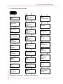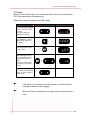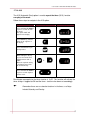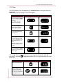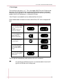
1
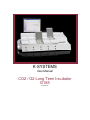
K-SYSTEMS
User Manual
CO2 / O2 Long Term Incubator
G185
Version 1.6
User manual for G185 CO2 / O2 flatbed incubator
Table of contents
1
General Information & Service .........................................................................................5
2
Explanation of Symbols Used in Manual ..........................................................................6
3
Safety symbols .................................................................................................................7
4
Precautions/warnings ......................................................................................................10
5
Important Safety Instructions ..........................................................................................11
6
General description.........................................................................................................12
6.1 Setup precautions......................................................................................................12
6.2 Accessories supplied.................................................................................................12
6.3 Copyright notice .......................................................................................................12
7
Product descriptions........................................................................................................13
8
Control panel for G185 incubator....................................................................................14
8.1 Compartment indicators ............................................................................................14
9
Mains connection............................................................................................................15
10 Gas connections..............................................................................................................16
11 HEPA / VOC filter .........................................................................................................18
11.1 Preparation of new filter capsule ...............................................................................18
11.2 Removing old filter...................................................................................................21
12 Menu ..............................................................................................................................23
12.1 Activating the heat and gas controls ..........................................................................24
13 Keyboard Lock ...............................................................................................................25
14 Alarms............................................................................................................................26
14.1 CO2 pressure alarm ...................................................................................................27
14.2 N2 pressure alarm......................................................................................................28
14.3 CO2 level alarm ........................................................................................................29
14.4 O2 level alarm ...........................................................................................................29
14.5 Temperature alarm....................................................................................................30
15 Setting the temperature ...................................................................................................31
16 Menu Function ...............................................................................................................32
17 Overview of the menu items ...........................................................................................33
17.1 Unit ………………….. ………………………………………………………………34
17.2 CO2 concentration Setpoint ......................................................................................35
17.3 CO2 concentration / calibration .................................................................................36
2
User manual for G185 CO2 / O2 flatbed incubator
17.4 CO2 regulator ...........................................................................................................37
17.5 Oxygen concentration setpoint ..................................................................................38
17.6 Oxygen Concentration / Calibration ..........................................................................39
17.7 O2 regulator..............................................................................................................40
17.8 CO2 flow rate ...........................................................................................................41
17.9 N2 flow rate..............................................................................................................42
17.10 PC/PDA data logger...............................................................................................43
17.11 Surface Temperatures.............................................................................................45
17.11.1 Calibration of Zone 1 .......................................................................................47
17.11.2 Calibration of Zone 2 .......................................................................................48
17.11.3 Calibration of Zone 3 .......................................................................................49
17.11.4 Calibration of Zone 4 .......................................................................................50
17.11.5 Calibration of Zone 5 .......................................................................................51
17.11.6 Calibration of Zone 6 .......................................................................................52
17.12 Regulation factor....................................................................................................53
17.13 Timer setting..........................................................................................................54
17.14 St.St .......................................................................................................................55
17.15 Heat .......................................................................................................................56
17.16 A-St .......................................................................................................................57
17.17 Hour ......................................................................................................................58
17.18 UV light.................................................................................................................59
17.19 Pressure of incoming CO2 gas ................................................................................60
17.20 Pressure of incoming N2 gas...................................................................................61
17.21 Decontamination....................................................................................................62
17.22 Reset......................................................................................................................63
17.23 Logic firmware ......................................................................................................64
18 Front chamber keys ........................................................................................................65
19 Temperature validation ...................................................................................................70
20 Gas level validation ........................................................................................................74
20.1 Gas level validation through gas sample port ............................................................74
20.2 Gas level validation through each gas chamber .........................................................76
21 AC cooling fan ...............................................................................................................79
22 Alarm switch for external dialling system .......................................................................80
23 Writing pads for the compartment lids and penholder. ....................................................82
3
User manual for G185 CO2 / O2 flatbed incubator
24 Maintenance ...................................................................................................................83
25 Troubleshooting..............................................................................................................84
26 Technical assistance........................................................................................................87
4
User manual for G185 CO2 / O2 flatbed incubator
1 General Information & Service
COPYRIGHT
This manual contains information that is subject to copyright. All rights reserved. This
manual should not be photocopied, otherwise copied or distributed, completely or in
part, without the approval of K-SYSTEMS Kivec Biotec.
Users of K-SYSTEMS Kivex Biotec products should not hesitate to contact us if there
are any unclear points or ambiguities in this manual.
K-SYSTEMS
Kivex Biotec A/S
Klintehøj vænge 3-5
3460 Birkerød
Denmark
Tel.: +45 45 99 56 00
Fax: +45 45 99 56 19
E-mail: [email protected]
Internet: www.K-SYSTEMS.dk
Service address:
Please contact your local K-SYSTEMS Kivex Biotec distributor for details.
CAUTION: If the equipment is used in a manner not specified by this manual, the
safety of the user may be at risk and the equipment may be damaged. Always use
the equipment as outlined in this instruction manual.
5
User manual for G185 CO2 / O2 flatbed incubator
2 Explanation of Symbols Used in Manual
NOTE
Used to direct attention to a specific item.
WARNING
Used to warn the user against a specific item.
DANGER
Used when caution is needed.
HELP
Used when the help of an assistant is needed.
6
User manual for G185 CO2 / O2 flatbed incubator
3 Safety symbols
The G185 contains high voltage components that may be hazardous. Therefore it is
strongly recommended that in order to reduce the risk of electric shock, the button
cover not to be removed.
This equipment doesn’t contain any serviceable parts. It is therefore recommended to
have qualified service personnel performing any service needed on the equipment.
There are several types of labels attached to a G185. A complete list of labels are
shown on table below.
This device contains UV light with
a wave length of 254nm . Always
power off by removing mains
power cord from socket before
removing cover.
Exposure to UV radiation
may cause serious damages to
your skin and eyes.
Warning on the back of incubator
indicates that an earth connection
is needed.
This ‘bolt of lightning’ indicates
un-insulated materials within your
unit may cause an electrical
shock. For the safety of everyone
in the laboratory please don’t
remove any covering.
Warning label on mains wire.
Main product label.
7
User manual for G185 CO2 / O2 flatbed incubator
Warning for 110/115V countries.
Warranty label – Warning.
The symbol indicates that the unit
contains high sensitive electronic
components which can be
damaged by static electricity.
Internal label placed next to every
earth wire.
K-SYSTEMS brand logo.
8
User manual for G185 CO2 / O2 flatbed incubator
Info labels on the back of the G185
Always have red cap on un-used gas input and outputs.
Chamber numbers on the front of the incubator, can be seen in the left corner of
each chamber.
Label on the large heating compartment.
Please note that there is no gas control in the large compartment.
The large compartment is not intended for any long term incubation
purposes.
9
User manual for G185 CO2 / O2 flatbed incubator
4 Precautions/warnings
•
Do not use product if package is damaged.
•
Do not use product without a proper VOC filter attached.
•
Do not use this product at temperatures exceeding 30oC.
•
Do not block the cooling fan while in operation.
•
Never use a non-K-SYSTEMS filter.
•
Use only 100% pure CO2 and 100% pure N2 gas.
•
Always use HEPA filter for input CO2 and N2 gas.
•
Always keep red cap on unused gas and sample lines.
•
Read and understand the user manual completely before use.
•
NEVER block gas supply pins placed in the middle of each of the 10
gas chambers.
•
Make sure that CO2 and N2 gas supply pressures are kept stable at
1.0 bar.
•
Always connect power cord to a proper grounded outlet.
•
VOC filters must be changed in the interval described in the manuals.
•
UV lamp must be changed in the interval described in the manuals.
•
O2 sensor must be changed in the interval described in the manuals.
•
Big compartment only to be used to keep things warmed.
•
Never leave lids open for more than 10 seconds.
•
Perform temperature and gas calibration in the intervals described in
the manuals.
•
To reduce the risk of fire or electric shock, this equipment should not
be exposed to rain or moistures and objects filled with liquids.
10
User manual for G185 CO2 / O2 flatbed incubator
5 Important Safety Instructions
•
Read the safety instructions before using equipment.
•
Always keep these instructions.
•
Heed all warnings.
•
Follow all instructions.
•
Do not use this apparatus near water.
•
Do not block any ventilation openings.
•
Do not install near any heat sources such as radiators, heat registers,
stoves or other apparatus that produce heat.
•
Do not defeat the safety purpose of the grounding-type plug.
A grounding type plug has two blades and a third prong is provided
for your safety. If the provided plug does not fit into your outlet,
consult an electrician for replacement of the obsolete outlet.
•
Protect the power cord from being walked on or pinched, particularly
at plugs, convenience receptacles, and the point where they exit from
apparatus.
•
Unplug this apparatus during lightning, storms or when unused for a
long period of time.
•
Refer all servicing to qualified service personnel.
Servicing is required according to service manual or if the apparatus
has been damaged in any way, such as if the apparatus have been
dropped, exposed to rain or moisture, or does not operate normally.
11
User manual for G185 CO2 / O2 flatbed incubator
6 General description
This unit does not contain any user serviceable parts. Please leave
all maintenance work to qualified personnel.
6.1 Setup precautions
In order to avoid any possible damages’ to this system please follow all setup
precautions described in this chapter.
Finding a suitable location
Place this unit on a flat, hard and stable surface. Never place the unit on a carpet or
similar surfaces.
Never place this unit on top of other equipment that might heat it up.
Space for ventilation
Never put anything under this unit, this might block the ventilation openings causing
possible damage to system.
Place this unit in a location with adequate ventilation to prevent internal heat build up.
Allow at least 10 cm clearance from the rear, 30 cm from the top and 20 cm from left
and right to prevent overheating.
Avoid high temperature, moisture, water and dust
This unit must not be exposed to dripping or splashing.
This unit is intended for indoor purposes only.
6.2 Accessories supplied
• 3 VOC filter capsules (plus one installed).
•
2 HEPA filter for input gas supply.
•
10 warming blocks for Nunc® OR Falcon®.
•
10 magnet pads to be attached to lids for writing & Pack of Pens
•
1 CD-ROM containing K-SYSTEMS A/S data logging software
•
1 Data Extension Cord & 1 USB Converter
•
2 Silicone Tube Sealing Rings & Silicone Tube (3 m)
•
Test Lid
•
1 CD-ROM containing USB converter drivers
6.3 Copyright notice
The making of any unauthorized copies of copy-protected material, including
manuals and software is an infringement of copy rights and constitute a criminal
offence.
12
User manual for G185 CO2 / O2 flatbed incubator
7 Product descriptions
The G185 incubator is a new generation of desktop CO2 and O2 incubator used for
maintaining an optimal environment for the development of embryos and blastocysts.
Direct warming of the dishes in the chambers gives superior temperature conditions
in comparison to conventional incubators.
The G185 incubator is composed of 10 separate culture heat chambers each having
its own lid and a flat warming block insert. The warming blocks are customized to
accommodate several types of dishes for either Falcon® or Nunc®. In addition the
G185 incubator has a large warmed compartment on the side that can hold culture
media.
For maximum performance the system has 6 separate temperature controllers,
controlling and regulating the temperature in the culture chambers and the large
compartment.
The Incubator needs 100% CO2 and 100% N2 in order to be able to control the CO2
and O2 concentrations in the culture chambers.
The incubator has been developed and optimized for tissue culturing with an overlay
of either Paraffin or mineral oil.
The incubator can be connected to a pc running the K-SYSTEMS data logging
software for long term data logging and data storage.
Also an external dialler1 can be connected to the incubator to ensure maximum
safety and reliability.
Open culture may lead to evaporation and a change in pH.
1
External dialler is an option. Please contact your K-SYSTEMS sales representative in your country
for more information.
13
User manual for G185 CO2 / O2 flatbed incubator
8 Control panel for G185 incubator
In the below table the control panel is explained.
(Alarm button)
- is used to mute an audible alarm.
(Standby –On)
- Turns on this unit or turns off to normal
standby mode.
(Display panel)
- Shows information about the current status of
the unit
(Setpoint)
- Is used to select item in the menu in order to
change their status. It is also used to change
temperature and gas setpoints.
(Arrow keys up and down)
- Are used to navigate through the menu and
changes values for temperature and gas
concentrations
8.1
Compartment indicators
The compartment indicators are used to indicate whether a compartment is occupied
or not.
14
User manual for G185 CO2 / O2 flatbed incubator
9
Mains connection
The G185 comes with a non detachable mains power cord. The power cord is
prepared for the country in which the unit is intended to be used in. Insert this in a
suited mains supply that is grounded.
Do not defeat the safety purpose of the grounding-type plug.
A grounding type plug has two blades and a third prong is provided
for your safety. If the provided plug does not fit into your outlet,
consult an electrician for replacement of the obsolete outlet.
The power requirement is: 230V 50 Hz OR 115V 60Hz and must be specified by
customer prior to order.
Connecting the unit to a wrong voltage will cause serious damages
to the system.
15
User manual for G185 CO2 / O2 flatbed incubator
10 Gas connections
On the back of the unit there are two gas inlets and one gas sample port outlet.
These ports are marked “CO2”, “N2” and “Gas sample port”.
The CO2 inlet should be connected to 100% pure CO2.
The N2 inlet should be connected to 100% pure N2 if low oxygen conditions are
required. O2 control in the compartments is available in the range from 20%- 2% by
infusing the N2.
Gas pressure for both inlets should be 1.0 bar (14.5 PSI) and must be
kept stable.
Always use a high quality pressure regulator for both gases.
16
User manual for G185 CO2 / O2 flatbed incubator
Remove the red cap for the gas inlet that is needed.
Take care not to loose the cap as it will be needed when gas is not
connected to the unit.
Connect the CO2 gas to the CO2 inlet with a suitable silicone tube.
Connect the N2 inlet to the Nitrogen Bottle in a similar way.
If no Oxygen control is needed leave the red cap on the N2 inlet.
Never run the unit with an inlet or outlet NOT covered by a red cap.
17
User manual for G185 CO2 / O2 flatbed incubator
11 HEPA / VOC filter
The combined HEPA and VOC filter is mounted on the side of the unit for easy
access and replacement.
11.1 Preparation of new filter capsule
The needed parts are: The VOC filter, two pieces of silicone tube sealing rings. The
two blue caps that are installed on the filter when unwrapped can be discarded.
Correct filter performance is crucial for the system performance.
Filter element should be changed every 3 months. Mark the date when it
is put on and make sure to keep this interval.
18
User manual for G185 CO2 / O2 flatbed incubator
Start by putting the silicone tube sealing ring on each side of the new filter element. It
must be put on so that it touches the base of the filter fitting.
Press one end of the filter (remember flow direction) into the stationary side of the
filter holder. It should align fully with the base of the filter holder.
19
User manual for G185 CO2 / O2 flatbed incubator
Then fit the other side of the filter into the sliding part of the filter holder and slide it
into place. It may be necessary to twist the filter element gently to get it to connect
fully.
Notice the flow direction on the side of the filter element (indicated by an
arrow on the label) MUST be the same as shown on the side of G185.
A filter element that has been fitted incorrectly will cause the unit
not to work as intended.
Filter correctly installed
20
User manual for G185 CO2 / O2 flatbed incubator
Flow direction as marked on the G185.
11.2 Removing old filter
The filter is removed by gently rotation the filter element with one hand and pulling
back the sliding part of the filter holder.
21
User manual for G185 CO2 / O2 flatbed incubator
Never run the G185 with the filter element missing.
22
User manual for G185 CO2 / O2 flatbed incubator
12 Menu
In the next chapters the functions associated with the keyboard and the menu items
explained.
The table below shows the main keys and their purposes.
(Alarm button)
- is used to mute an audible alarm.
(Standby –On)
- Turns on this unit or turns off to normal
standby mode.
(Display panel)
- Shows information about the current status of
the unit
(Setpoint)
- Is used to select item in the menu in order to
change their status. It is also used to change
temperature and gas setpoints.
(Arrow keys up and down)
- Are used to navigate through the menu and
changes values for temperature and gas
concentrations
23
User manual for G185 CO2 / O2 flatbed incubator
12.1 Activating the heat and gas controls
The heat and gas controls are activated using the heat (
) button2.
Soon after system activation the main display will alternate the reading between the
following 3 parameters:
Tp
= Temperature in °C or °F (°C is default)
Co2.C
= CO2 Concentration in %
O2.C
= O2 Concentration in %
This is illustrated in the below table.
Action
Display
Tp = Temperature in °C
or °F (default is °C)
After ‘tp’ has been shown,
the actual temperature will
be displayed for a few
seconds.
Co2.C = CO2 Concentration
in %
After ‘CO2.C’ has been
shown, the actual CO2 gas
concentration will be
displayed for a few seconds.
O2.C = O2 Concentration in
%
After ‘O2.C’ has been shown,
the actual O2 gas
concentration will be
displayed for a few seconds.
If CO2 regulation is deactivated the system will show ‘OFF’ right after
‘CO2.C’ has been displayed.
If O2 regulator is deactivated the system will display ‘OFF’ right after
‘O2.C’ has been displayed.
2
Activation of CO2 and O2 controls require that the CO2 regulator ’CO2.r’ and O2 regulator ’O2.r’ have been
activated within the menu.
24
User manual for G185 CO2 / O2 flatbed incubator
13 Keyboard Lock
In order to prevent any change of the settings by mistake, the G185 has a built in
keyboard lock that can be activated/de-activated using the keyboard buttons.
Please follow the following instructions to lock and un-lock the keyboard.
Action
Press arrow up and arrow down along with the
alarm key at the same time will lock the
keyboard.
Key
+
When pressing a random key the display will
show “lock”, while keyboard is locked.
To unlock the keyboard press SP along with
Arrow up and down keys at the same time.
+
If the keyboard lock has been activated and any buttons is pressed
‘Lock’ will be shown on the display to indicate that the keyboard is
locked.
Kindly note that the alarm still can be muted when key lock is engaged.
25
User manual for G185 CO2 / O2 flatbed incubator
14 Alarms
When the G185 is in an alarm mode a message will be shown on the display. The
below table contain a list of the alarm messages and an explanation of the alarms.
Alarm
Display
CO2 pressure alarm
CO2 level alarm
N2 pressure alarm
O2 level alarm
In the following chapters these alarm states are explained in more details.
26
User manual for G185 CO2 / O2 flatbed incubator
14.1 CO2 pressure alarm
If the CO2 gas supply is not attached correctly or wrong CO2 gas pressure is applied
to the system, the G185 will go into CO2 pressure alarm mode. “CO2.P” will be
displayed, indicating wrong incoming gas pressure.
Action
Key
Display
CO2 gas supply failure.
‘P’ stands for pressure.
A constant audible alarm is also activated which can be muted by pressing the alarm
button
.
, the “CO2.P” message on the display
By pressing the alarm button
will also disappear, but the red LED light will stay on until correct gas
pressure is applied to unit.
27
User manual for G185 CO2 / O2 flatbed incubator
14.2 N2 pressure alarm
If the N2 gas supply is not attached correctly or wrong N2 gas pressure is applied to
the unit, the G185 will go into alarm mode.
“n2.P” will be displayed, indicating wrong incoming nitrogen gas pressure.
Action
Key
Display
The gas supply is not
attached correctly or
empty.
‘P’ stands for pressure.
A constant audible alarm is also activated which can be muted by pressing the alarm
button
.
By pressing the alarm button
, the “N2.P” message on the display
will disappear but the red LED light will stay ON until correct gas
pressure is applied to unit.
28
User manual for G185 CO2 / O2 flatbed incubator
14.3 CO2 level alarm
CO2 level alarm is activated if the concentration of the CO2 gas is deviating by
than +− 1% from set value.
Remember when changing the set point more than ±1% from the current gas level
this will result in an CO2 level alarm. The same goes for all calibration adjustments.
Action
Key
Display
Gas concentration is
deviating by more than
one percent from set
value.
When there is an alarm an acoustic signal is also activated which can be
muted by pressing the alarm (
)button.
14.4 O2 level alarm
O2 level alarm is activated if the concentration of the O2 gas is deviating by more
than +− 1% from set value.
Remember when changing the set point more than ±1% from the current gas level
this will result in an CO2 level alarm. The same goes for all calibration adjustments.
Action
Key
Display
O2 gas concentration is
deviating by more than
one percent from set
value.
When there is an alarm an acoustic signal is also activated which can be
muted by pressing the alarm (
)button.
29
User manual for G185 CO2 / O2 flatbed incubator
14.5 Temperature alarm
All zones of the heating system can trigger a temperature alarm if they are more than
±0.5 degree C from the set point.
Remember when changing the set point more than ±0.5 degrees from the current
temperature this will result in an alarm. The same goes for all calibration
adjustments.
The alarm condition is indicated by a red LED light in the alarm key and a pulsating
audio signal that can be muted by pressing the alarm key once.
Action
Key
Display
To mute the alarm sound
press once.
Press once again and the
sound will no longer be
muted.
When there is a temperature alarm an acoustic signal is also activated
which can be muted by pressing the alarm (
)button.
The display will not change in any way and will stay at the point where it
was when the alarm started.
30
User manual for G185 CO2 / O2 flatbed incubator
15 Setting the temperature
The set temperature is 37.0oC by default. The set temperature can be adjusted in the
range from ambient to 49.0oC.
Changing the Set point for the temperature, follow these instructions:
Action
Key
Display
Press the button with the symbol
SP, the current set temperature
will be shown on the display.
To raise the set temperature
press and hold SP, then press
arrow UP. When the desired Setpoint is reached release both
keys.
To lower the Set-point
temperature press and hold SP,
then press arrow DOWN. When
the desired set-point is reached,
release both keys.
+
+
If SP and arrow UP or DOWN are pressed continuously the temperature
setting will change quickly. To change the temperature slowly, press one
step at a time.
31
User manual for G185 CO2 / O2 flatbed incubator
16 Menu Function
The user can access a number of advanced functions via the menu.
Please follow the below instructions for entering, exiting and navigating within the
menu.
Action
Key
Display
Press and hold UP+DOWN
key for 3 seconds to enter the
menu.
The first option “UNIT” will
appear in the display.
Press UP/DOWN key to
navigate within the Menu.
While holding the setpoint key
in, press either the arrow UP
or arrow DOWN key to change
values within the options.
Press and hold UP+DOWN
key for 3 seconds again to exit
the menu.
32
User manual for G185 CO2 / O2 flatbed incubator
17 Overview of the menu items
tn-1
UNIT
o
°C / F
CO.SP
Set Point for
CO2
Calibration of
Zone-1
heat
Timer for heater
tn-2
Calibration of
Zone-1
A-set
tn-3
hour
Auto set
CO2.C
CO2 concentration
Calibration of
Zone-3
Display time
CO2.r
CO2 regulator
O2.SP
tn-4
Calibration of
Zone-4
u-1
Uv light
O2 Set Point
co.pr
tn-5
O2.C
O2 concentration
CO2 pressure
Calibration of
Zone-5
n2.pr
O2.r
O2 regulator
tn-6
N2 pressure
Calibration of
Zone-6
CO2.F
int.t
CO2 flow
Regulation factor
n2.F
ti.st
N2 flow
Time setting
r232
st.st
Data logging
Start set
dc.nt
Decontamination
rest
Reset
uer.
Current logic
version
(Continue on next column) (Continue on next column)
33
User manual for G185 CO2 / O2 flatbed incubator
17.1 Unit
In the UNIT option the displayed temperature can be set either to degrees Celsius
or Fahrenheit. As default this is set to °C.
Follow these steps to navigate in the UNIT option.
Action
Key
Display
Press and hold UP+DOWN
key for 3 seconds to enter the
menu.
The option “UNIT” will appear
in the display.
Press and hold SP key to see
if °C or °F is chosen.
While holding the SP key in,
press either the arrow UP or
arrow DOWN key to toggle
o
between Celsius ( C) or
o
Fahrenheith ( F).
Press and hold UP+DOWN
key for 3 seconds again to exit
the menu.
34
User manual for G185 CO2 / O2 flatbed incubator
17.2 CO2 concentration Setpoint
‘Co.SP’ is the CO2 set point. This option is used to change the desired CO2
concentration in the system.
In order to change the CO2 setpoint, please follow below instructions.
Action
Key
Display
Press and hold
UP+DOWN key for 3
seconds to enter the
menu.
The option “UNIT” will
appear in the display.
Press arrow DOWN key
until the option “Co.SP”
appears in the display.
Press and hold the SP
key to see the current set
value for CO2
concentration.
Change by pressing and
holding the SP key and
arrow UP or DOWN.
+
Press and hold
UP+DOWN key for 3
seconds again to exit the
menu.
As default the CO2 setpoint (CO.SP) is set to 5.0 %.
35
User manual for G185 CO2 / O2 flatbed incubator
17.3 CO2 concentration / calibration
Co2.C is the CO2 calibration or a reading of the actual CO2 concentration in the
system.
Remember that the CO2 regulator must be activated before the concentration can be
viewed or changed.
Whenever an adjustment of the CO2 concentration is needed it can be done here by
following below instructions.
Action
Key
Display
Press and hold
UP+DOWN key for 3
seconds to enter the
menu.
The option “UNIT” will
appear in the display.
Press DOWN key until
the option “Co2.C”
appears in the display.
Press and hold the SP
key to have a reading of
the current CO2 volume.
Use SP key and arrow
UP or DOWN to adjust
the reading based on
reliable data from an
external gas analyzer.
+
Press and hold
UP+DOWN key for 3
seconds again to exit the
menu.
Please refer to next chapter to for instructions on how to activate CO2
regulator.
Please refer to chapter 20 for more details on gas level validation and
calibration procedures.
Calibration is done by adjusting the CO2 level according to a
measurement done on the gas sampling outlet using a precision CO2
measurement device only.
Changing the calibration value should only be done based on
certain measurement by a trained user or a technician.
36
User manual for G185 CO2 / O2 flatbed incubator
17.4 CO2 regulator
‘CO2.r’ is used to toggle the CO2 regulation ON/OFF.
As default the CO2 regulator is set to ‘ON’.
Follow the below instructions to activate/deactivate the CO2 regulator.
Action
Key
Display
Press and hold UP+DOWN
key for 3 seconds to enter
the menu.
The option “UNIT” will
appear in the display.
Press DOWN key until the
option “Co2.r” appears in
the display.
If CO2 regulation is not
needed, it can be switched
OFF here. The Default
value is ON. CO2 regulation
is switched to OFF by
holding the SP key while
pressing the arrow DOWN
key once.
+
When the CO2 regulation
has been set for OFF there
will not be shown any value
under the ‘CO2.C’ menu
point. It will display ‘OFF’ to
indicate that the regulator
has been deactivated by
user.
Press and hold UP+DOWN
key for 3 seconds to exit the
menu.
Always connect 100 % pure CO2 source to the CO2 gas inlet located on
the back of G185 before switching the regulator ‘ON’.
37
User manual for G185 CO2 / O2 flatbed incubator
17.5 Oxygen concentration setpoint
“O2.SP” is the O2 set point. This option is used to change the desired O2
concentration in the system.
In order to change the O2 setpoint, please follow below instructions.
Action
Key
Display
Press and hold
UP+DOWN key for 3
seconds to enter the
menu.
The option “UNIT” will
appear in the display.
Press DOWN key until
the option “o2.SP”
appears in the display.
Press and hold the SP
key to see the set value.
Change by pressing and
holding the SP key and
arrow UP or DOWN.
+
Press and hold
UP+DOWN key for 3
seconds again to exit the
menu.
As default the O2 setpoint (O2.SP) is set to 5.0%.
38
User manual for G185 CO2 / O2 flatbed incubator
17.6 Oxygen Concentration / Calibration
The item called ‘O2.C’ is found in the menu and is used for calibration or just having
a readout of the actual O2 concentration in the system.
Remember that O2 regulator must be activated before the concentration can be
shown/changed.
Whenever an adjustment of the O2 concentration is needed it can be done here by
following below instructions.
Action
Key
Display
Press and hold
UP+DOWN key for 3
seconds to enter the
menu.
The option “UNIT” will
appear in the display.
Press DOWN key until
the option “o2.C” appears
in the display.
Reading the actual O2
value is done by pressing
and holding the SP key.
Change by pressing and
holding the SP key and
arrow UP or DOWN.
+
Press and hold
UP+DOWN key for 3
seconds again to exit the
menu.
Please refer to next chapter to for instructions on how to activate O2
regulator.
Please refer to chapter 20 for more details on gas level validation and
calibration procedures.
Calibration is done by adjusting the O2 level according to a measurement
done on the gas sampling outlet by a precision O2 measurement device.
Changing the calibration value should only be done based on
certain measurement by a trained user or a technician.
39
User manual for G185 CO2 / O2 flatbed incubator
17.7 O2 regulator
‘O2.r’ is used to toggle the O2 regulation ON/OFF. If O2 regulation is not needed, the
oxygen regulator can be switched off here.
If low oxygen conditions are needed the O2 regulator must be switched to ON.
Follow the below instructions to activate/deactivate the O2 regulator.
Action
Key
Display
Press and hold
UP+DOWN key for 3
seconds to enter the
menu.
The option “UNIT” will
appear in the display.
Press DOWN key until
the option “o2.r” appears
on the display.
When the O2 regulation
has been set for “OFF”
there will not be shown
any value under the
‘o2.C’ menu point. It will
display “OFF”, to
indicate that the
regulator has been
deactivated by user.
+
Press and hold
UP+DOWN key for 3
seconds again to exit the
menu.
Always connect a 100 % pure N2 source to the gas inlet on the rear
before switching the regulation ON.
The Default status for the oxygen control is OFF.
40
User manual for G185 CO2 / O2 flatbed incubator
17.8 CO2 flow rate
“Co2.F” is the CO2 gas consumption. It is automatically measured by the system and
the actual consumption is shown.
In order to get a reading of current CO2 gas consumption, please follow below
instructions.
Action
Key
Display
Press and hold
UP+DOWN key for 3
seconds to enter the
menu.
The option “UNIT” will
appear in the display.
Press DOWN key until
the option “Co2.F”
appears in the display.
Pressing and holding the
SP key will give a
reading of the actual flow
rate.
Press and hold
UP+DOWN key for 3
seconds again to exit the
menu.
CO2 gas consumption is not a fixed value and may change in the
intervals from 0 l/h – 10 l/h.The necessary amount needed is
automatically calculated and adjusted by the system.
Remember that 100% pure and dry CO2 gas will bee needed to increase
the CO2 level in the system.
41
User manual for G185 CO2 / O2 flatbed incubator
17.9 N2 flow rate
“n2.F” is the N2 gas consumption. The necessary amount is automatically calculated
and adjusted by the system and the actual consumption is then shown.
In order to get a reading of current N2 gas consumption, please follow below
instructions.
Action
Key
Display
Press and hold
UP+DOWN key for 3
seconds to enter the
menu.
The option “UNIT” will
appear in the display.
Press DOWN key until
the option “n2.F”
appears in the display.
Pressing and holding the
SP key will give a
reading of the current
nitrogen consumption.
Press and hold
UP+DOWN key for 3
seconds again to exit the
menu.
N2 gas consumption is not a fixed value and may change in the intervals
from 0 l/h – 54 l/h.The necessary amount is automatically calculated and
adjusted by the system.
Remember that 100% pure and dry N2 will bee needed to reduce the
O2 level in the system. Remember also to activate the O2 regulation
as described in chapter 17.7.
42
User manual for G185 CO2 / O2 flatbed incubator
17.10 PC/PDA data logger
The next item in the menu is “r232”. This is the communication protocol with the PDA
or a Windows based PC. The communication can be toggled between PC, PDA or
OFF here.
Action
Key
Display
Press and hold
UP+DOWN key for 3
seconds to enter the
menu.
The option “UNIT” will
appear in the display.
Press DOWN key until
the option “r323”
appears in the display.
Press key UP or DOWN
once while holding the
SP to turn on the
communication port.
Data logging is
prepared and sent for a
PC (default).
+
When the required
setting is set let go of
the SP key.
Hold the ‘SP’ button and
press ‘down’ once, this
will change the display
reading to “PDA”. Now
data are being prepared
and send for a PDA
attached to the G185.
Hold the ‘SP’ button and
press ‘down’ once more,
this will change the
display reading to
“OFF”. No data is being
sent to the
communication port.
+
Press and hold
UP+DOWN key for 3
seconds again to exit
the menu.
43
User manual for G185 CO2 / O2 flatbed incubator
Having the parameter set incorrectly when no PDA or PC is attached will
not make any difference. Only switching to “OFF” when the PDA or PC is
attached will impact on the datalogger software.
Communication protocol is set to ‘PC’ by default.
Please refer to the enclosed “Installation instruction for datalogger
software” for further instruction for datalogger installation.
Never attempt to switch off the dataflow when the PDA or PC is
logging data. Stop the program first on the PDA or the PC.
44
User manual for G185 CO2 / O2 flatbed incubator
17.11 Surface Temperatures
In this section the temperature controls of the G185 is described.
There are 6 separate controls for the temperature on the G185.
Each controller is responsible in controlling the temperature of a separate zone.
Therefore each of the 6 available zones is equipped with its own separate
temperature sensor and heater, allowing the user to adjust the temperature within
every zone separately and achieve higher precision.
Each zone can be calibrated separately using the item that corresponds to the
respective zone in the menu.
These items are placed in the menu and they are named: Tn-1, Tn-2, Tn-3, Tn-4, Tn5 and Tn-6.
An overview of the zones associated with the tune functions is shown on table below.
Zone name
tn-1
tn-2
tn-3
tn-4
tn-5
tn-6
Chambers in zone
Chamber no. 5 and 10
Chamber no. 4 and 9
Chamber no. 3 and 8
Chamber no. 2 and 7
Chamber no. 1 and 6
Big compartment
45
User manual for G185 CO2 / O2 flatbed incubator
From the table above we can see that compartment no. 5 and 10 is controlled by ‘Tn1’.
In order to adjust/calibrated the temperature of this zone please find item called ‘tn-1’
and adjust using high precision thermometer.
Calibration of temperature is done by adjusting the tn-x (where x is
the zone number) according to a measurement done on both of the
chambers within the zone by a precision Thermometer.
After temperature adjustment allow at least 15 minutes for the
temperature to stabilized, use the thermometer to verify correct
temperatures on each zone.
Be careful when changing the calibration settings to only change the tune value of
the place where the measurement is actually done. Give the system time to adjust.
Remember that if one warmed area is much warmer than the area in its
proximity there will be cross over heating. Calibration is best done by
starting out with Tn-1 and then Tn-2 to Tn-6. Then letting the system
stabilize and repeating the procedure.
Please refer to chapter 19 for a more detailed description of temperature
validation.
46
User manual for G185 CO2 / O2 flatbed incubator
17.11.1 Calibration of Zone 1
The item called “Tn-1” in the menu is used to calibrate the temperature in zone1.
Action
Key
Display
Press and hold
UP+DOWN key for 3
seconds to enter the
menu.
The option “UNIT” will
appear in the display.
Press DOWN key until
the option “tn-1” appears
on the display.
Pressing and holding the
SP key will give a reading
of the current temperature
of zone 1 (chamber no. 5
and 10)
Change according to a
precision thermometer, by
pressing and holding the
SP key and arrow UP or
DOWN.
+
Press and hold
UP+DOWN key for 3
seconds again to exit the
menu.
‘tn-1’ is used to adjust the temperature of compartment 5 and 10.
Adjust according to a high precision measurement done in a dish with
media under mineral oil located in compartment 5 and 10.
Please refer to chapter 19 for a detailed description of temperature
measurement on G185.
47
User manual for G185 CO2 / O2 flatbed incubator
17.11.2 Calibration of Zone 2
The item called “Tn-2” in the menu is used to calibrate the temperature in the zone2.
Action
Key
Display
Press and hold
UP+DOWN key for 3
seconds to enter the
menu.
The option “UNIT” will
appear in the display.
Press DOWN key until
the option “tn-2” appears
on the display.
Pressing and holding the
SP key will give a reading
of the current temperature
of zone 2 (chamber no. 4
and 9)
Change according to a
precision thermometer, by
pressing and holding the
SP key and arrow UP or
DOWN.
+
Press and hold
UP+DOWN key for 3
seconds again to exit the
menu.
‘tn-2’ is used to adjust the temperature of compartment 4 and 9.
Adjust according to a high precision measurement done in a dish with
media under mineral oil located in compartment 4 and 9.
Please refer to chapter 19 for a detailed description of temperature
measurement on G185.
48
User manual for G185 CO2 / O2 flatbed incubator
17.11.3 Calibration of Zone 3
The item called “Tn-3” in the menu is used to calibrate the temperature in the zone3.
Action
Key
Display
Press and hold
UP+DOWN key for 3
seconds to enter the
menu.
The option “UNIT” will
appear in the display.
Press DOWN key until
the option “tn-3” appears
on the display.
Pressing and holding the
SP key will give a reading
of the current temperature
of zone 3 (chamber no. 3
and 8)
Change according to a
precision thermometer, by
pressing and holding the
SP key and arrow UP or
DOWN.
+
Press and hold
UP+DOWN key for 3
seconds again to exit the
menu.
‘tn-3’ is used to adjust the temperature of compartment 3 and 8.
Adjust according to a high precision measurement done in a dish with
media under mineral oil located in compartment 3 and 8.
Please refer to chapter 19 for a detailed description of temperature
measurement on G185.
49
User manual for G185 CO2 / O2 flatbed incubator
17.11.4 Calibration of Zone 4
The item called “Tn-4” in the menu is used to calibrate the temperature in the zone4.
Action
Key
Display
Press and hold
UP+DOWN key for 3
seconds to enter the
menu.
The option “UNIT” will
appear in the display.
Press DOWN key until
the option “tn-4” appears
in the display.
Pressing and holding the
SP key will give a reading
of the current temperature
of zone 4 (chamber no. 2
and 7)
Change according to a
precision thermometer, by
pressing and holding the
SP key and arrow UP or
DOWN.
+
Press and hold
UP+DOWN key for 3
seconds again to exit the
menu.
‘tn-4’ is used to adjust the temperature of compartment 2 and 7.
Adjust according to a high precision measurement done in a dish with
media under mineral oil located in compartment 2 and 7.
Please refer to chapter 19 for a detailed description of temperature
measurement on G185.
50
User manual for G185 CO2 / O2 flatbed incubator
17.11.5 Calibration of Zone 5
The item called “Tn-5” in the menu is used to calibrate the temperature in the zone5.
Action
Key
Display
Press and hold
UP+DOWN key for 3
seconds to enter the
menu.
The option “UNIT” will
appear in the display.
Press DOWN key until
the option “tn-5” appears
on the display.
Pressing and holding the
SP key will give a reading
of the current temperature
of zone 5 (chamber no. 1
and 6)
Change according to a
precision thermometer, by
pressing and holding the
SP key and arrow UP or
DOWN.
+
Press and hold
UP+DOWN key for 3
seconds again to exit the
menu.
‘tn-4’ is used to adjust the temperature of compartment 1 and 6.
Adjust according to a high precision measurement done in a dish with
media under mineral oil located in compartment 1 and 6.
Please refer to chapter 19 for a detailed description of temperature
measurement on G185.
51
User manual for G185 CO2 / O2 flatbed incubator
17.11.6 Calibration of Zone 6
The item called “Tn-6” in the menu is used to calibrate the large compartment used
for dry bath incubation purposes.
Action
Key
Display
Press and hold
UP+DOWN key for 3
seconds to enter the
menu.
The option “UNIT” will
appear in the display.
Press DOWN key until
the option “tn-6” appears
on the display.
Pressing and holding the
SP key will give a reading
of the current temperature
of zone 6 (Large
compartment)
Change according to a
precision thermometer, by
pressing and holding the
SP key and arrow UP or
DOWN.
+
Press and hold
UP+DOWN key for 3
seconds again to exit the
menu.
The large compartment is only warmed and has no gas control.
Please refer to chapter 19 for a detailed description of temperature
measurement on G185.
52
User manual for G185 CO2 / O2 flatbed incubator
17.12 Regulation factor
The INT.T (Integral Time) option is for changing the base value for the PID controller.
This should not be attempted by unauthorised persons. If set at a different level the
controlling principle will be affected.
Action
Key
Display
Press and hold
UP+DOWN key for 3
seconds to enter the
menu.
The option “UNIT” will
appear in the display.
Press DOWN key until
the option “int.t” appears
on the display.
Pressing and holding the
SP key will give a reading
of the current setting.
The value for regulation
factor can be change
using SP key along with
arrow UP or DOWN.
+
Press and hold
UP+DOWN key for 3
seconds again to exit the
menu.
From the factory it is set to a closely calculated value specific for the
model.
Do not change the value here unless authorization has
been given directly by K-SYSTEMS.
53
User manual for G185 CO2 / O2 flatbed incubator
17.13 Timer setting
The “ti.St” refers to the timer functions, which means time set.
Follow these steps to navigate in the “Ti.St” option.
Action
Key
Display
Press and hold UP+DOWN
key for 3 seconds to enter
the menu.
The option “UNIT” will
appear in the display.
Press DOWN key until the
option “Ti.St.” appears on
the display.
Press and hold SP key to
change values.
Change the hour 0-24 by
pressing and holding the
SP key and then changing
the hours with the arrow
down key.
Change the minutes from
00-59 in a similar way but
this time using the arrow up
key.
+
+
When the time is set
correctly leave this menu
point by letting go of the SP
key and pressing the arrow
up and down.
54
User manual for G185 CO2 / O2 flatbed incubator
17.14 St.St
The next menu point is “St.St”. This means Start Set and is where timer function is
set to switch ON for the G185.
Follow these steps to navigate in the St.St. option.
Action
Key
Display
Press and hold UP+DOWN
key for 3 seconds to enter
the menu.
The option “UNIT” will
appear in the display.
Press DOWN key until the
option “St.St.” appears in
the display.
Press and hold SP key to
change values.
Change the hours 0-24 by
pressing and holding the
SP key and then pressing
arrow down key.
Change the minutes from
00-59 in a similar way but
this time using the arrow up
key.
+
+
When the time is set
correctly leave this menu
point by letting go of the SP
key and pressing the arrow
down.
55
User manual for G185 CO2 / O2 flatbed incubator
17.15 Heat
When the start time has been set the next menu item “heat” must be switched to
“ON” if the warmed area should warm up.
Follow these steps to navigate in the HEAT option.
Action
Key
Display
Press and hold UP+DOWN
key for 3 seconds to enter
the menu.
The option “UNIT” will
appear in the display.
Press DOWN key until the
option “hEAt.” appears in
the display.
Press and hold SP key to
change values.
While holding the SP key
in, press the arrow UP to
select between “ON” or
“OFF”.
When the required setting
is activated, let go of the
SP key.
+
Press and hold UP+DOWN
key for 3 seconds again to
exit the menu.
If the Heat is set to off when the timer function is set nothing will be
switched on when the timer engages.
Make sure that all compartments are empty when the timer function is
used.
56
User manual for G185 CO2 / O2 flatbed incubator
17.16 A-St
The A-St (Automatic Start) option is used to repeat the timer (St.St.) function
everyday of the week.
Follow these steps to navigate in the A-St option.
Action
Key
Display
Press and hold UP+DOWN
key for 3 seconds to enter
the menu.
The option “UNIT” will
appear in the display.
Press DOWN key until the
option “A-St.” appears in
the display.
Press and hold SP key to
change values.
While holding the SP key
in, press the arrow UP to
toggle between “ON” or
“OFF”.
When the required setting
is activated, let go of the
SP and arrow keys.
+
Press and hold UP+DOWN
key for 3 seconds again to
exit the menu.
Penultimate menu point for the timer function is “A-St”. This function will activate the
timer all days if toggled to ON and the time + start time has been set accordingly.
Remember there are no calendar functions in the timer, so all days
include Saturday and Sunday.
57
User manual for G185 CO2 / O2 flatbed incubator
17.17 Hour
The HOUR option gives the opportunity to show the time on the display when the
heat is off.
Follow these steps to navigate in the HOUR option.
Action
Key
Display
Press and hold UP+DOWN
key for 3 seconds to enter
the menu.
The option “UNIT” will
appear in the display.
Press arrow DOWN key
until the option “HOUR”
appears in the display.
Press and hold SP key to
change values.
While holding the SP key
in, press either the arrow
UP or arrow DOWN key to
select between “ON” o´r
“OFF”.
When the required setting
is activated, let go of the
SP key.
Press and hold UP+DOWN
key for 3 seconds again to
exit the menu.
It is also possible to toggle between the temperature display and the clock by
pressing SP and heat (
off the unit.
).
Action
Remember to press SP first as you otherwise will switch
Key
Display
Press and hold SP key.
While holding the “SP”
key in, press the HEAT
key once, then let go of
the “SP” key. The display
now shows the time.
+
+
58
User manual for G185 CO2 / O2 flatbed incubator
17.18 UV light
The next item in the menu is “u1”. This is the toggle ON/OFF for the UV-light inside
the circuit. The UV light will make sure that no contamination occurs in the circuit.
When correctly set up there is full Carbon filtering of the air so that any harmful by
product from the UV light process is removed at all times.
If the UV light is not needed it can be switched off from the menu.
Please follow below instruction on how to switch ON or OFF for the integrated UV
light.
Action
Key
Display
Press and hold UP+DOWN
key for 3 seconds to enter
the menu.
The option “UNIT” will
appear in the display.
Press arrow DOWN key
until the option “u1”
appears in the display.
Press and hold SP key to
see actual status.
Press and hold SP while
pressing arrow DOWN
once to change status of
UV light.
Press and hold UP+DOWN
key for 3 seconds again to
exit the menu.
The UV light will automatically switch off when the unit is turned off.
For optimal air purification reasons it is recommended to have the UV
light set to ON when unit is being used.
59
User manual for G185 CO2 / O2 flatbed incubator
17.19 Pressure of incoming CO2 gas
The next item in the menu is “Co.Pr” and stands for CO2 pressure. This function can
only be used to monitor the CO2 gas pressure inside the unit.
In order to check the internal CO2 gas pressure please follow these instructions.
Action
Key
Display
Press and hold UP+DOWN
key for 3 seconds to enter
the menu.
The option “UNIT” will
appear in the display.
Press arrow DOWN key
until the option “Co.Pr”
appears in the display.
Press and hold SP key to
monitor internal CO2 gas
pressure.
Press and hold UP+DOWN
key for 3 seconds again to
exit the menu.
The actual CO2 gas pressure in the circuit is shown (normally between 0.35 – 0.65).
Remember that the inside pressure is always lower than what is shown
on the outside regulator on the gas bottle. This is because there is a built
in pressure limiter in the circuit.
60
User manual for G185 CO2 / O2 flatbed incubator
17.20 Pressure of incoming N2 gas
The next item in the menu is n2.Pr and stands for N2 pressure. This function can only
be used to monitor the N2 gas pressure inside the unit.
In order to check the internal N2 gas pressure please follow these instructions.
Action
Key
Display
Press and hold UP+DOWN
key for 3 seconds to enter
the menu.
The option “UNIT” will
appear in the display.
Press DOWN key until the
option “n2.Pr” appears in
the display.
Press and hold SP key to
check the actual N2 gas
pressure (normally
between 0.35 – 0.65 ).
Press and hold UP+DOWN
key for 3 seconds again to
exit the menu.
By pressing the ‘SP’ button the actual N2 gas pressure is shown (normally between
0.35 – 0.65).
Remember that the inside pressure is always lower than what is shown
on the outside regulator on the gas bottle. This is because there is a built
in pressure limiter in the circuit.
61
User manual for G185 CO2 / O2 flatbed incubator
17.21 Decontamination
The next item in the menu is “dCnt” which stands for decontamination. This function
enables the user to heat up the whole heated area (zone 1 to zone 6) up to 60°C
for approx. 1 hour in order to decontaminate the whole heated surface.
The decontamination system is equipped with a timer that automatically stops the
decontamination process when the desired temperature has been reached and
brings the system back to normal status.
WHILE DECONTAMINATION PROCESS IS ACTIVE, ALL GAS
REGULATIONS ARE DEACTIVATED. AN ACOUSTIC ALARM WILL
WARN THE USER ABOUT RISING TEMPERATURES. THE ACTUAL
TEMPERATURE AND DECOMINATION TIME LEFT WILL BE
CONSTANTLY BEE SHOWN ON THE DISPLAY. THE SYSTEM WILL
ALSO WARN THE USER ABOUT THE HOT SURFACE
TEMPERATURES.
To activate the decontamination process, please follow the instructions below.
Action
Key
Display
Press and hold UP+DOWN
key for 3 seconds to enter
the menu.
The option “UNIT” will
appear in the display.
Press DOWN key until the
option “dCnt” appears in
the display.
Hold the SP button while
pressing arrow UP or
DOWN buttons to toggle
the decontamination OFF
or bring it back ON again.
+
Press and hold UP+DOWN
key for 3 seconds again to
exit the menu.
AFTER END DECONTAMINATION PROCESS THE UNIT WILL STILL
BE HOT. DO NOT USE THE DEVICE UNTIL THE TEMPERATURE
AND GAS LEVELS ARE BACK TO NORMAL. IT IS RECOMMENDED
TO TEST THE TEMPERATURE AND GAS CONCENTRATIONS
BEFORE USE TO ENSURE CORRECT LEVELS.
62
User manual for G185 CO2 / O2 flatbed incubator
17.22 Reset
Next item in the menu is the function “REST”. This is the overall back to factory
default settings function.
To restore factory settings please follow the instruction below.
Action
Key
Display
Press and hold UP+DOWN
key for 3 seconds to enter
the menu.
The option “UNIT” will
appear in the display.
Press arrow DOWN key
until the option “REST”
appears in the display.
Press and hold SP key to
change values.
While holding the SP key
in, press either the arrow
UP or arrow DOWN key.
When the display shows “---“,* let go of the “SP” key.
Press and hold UP+DOWN
keys for 3 seconds again to
exit the menu.
A complete restore will be done.
63
User manual for G185 CO2 / O2 flatbed incubator
17.23 Logic firmware
The logics installed on your G185 is upgradeable. Whenever an important update is
available it will be distributed to our distributers around the world who will make sure
that your incubator runs with the newest available logic firmware.
Please follow these steps to check the logic firmware which is currently installed on
your unit.
Action
Key
Display
Press and hold UP+DOWN
key for 3 seconds to enter
the menu.
The option “UNIT” will
appear in the display.
Press DOWN key until the
option “uEr” appears in the
display.
Press and hold SP key to
check the unit’s current
firmware version.
Press and hold UP+DOWN
key for 3 seconds again to
exit the menu.
64
User manual for G185 CO2 / O2 flatbed incubator
18 Front chamber keys
On the sloping front of the G185 there are 10 buttons located. They are numbered
from 1 to 10. Each button corresponds to one compartment.
The compartments will be labelled to show which specific compartment corresponds
to which button. Should the labels have been removed the order is also listed below:
65
User manual for G185 CO2 / O2 flatbed incubator
Pressing a key will toggle the light in the key on/off. This light can be used as an
indication/warning that the compartment is in use and should not be opened.
Never leave a compartment lid open for unnecessary long time.
Each opening should be minimized to less than 10 seconds under
normal use.
Inside the compartment there is a warmed area that covers the bottom. In the middle
the gas intake and outlet is located. This must be kept free at all times.
If the gas inlet/outlet in the middle of each compartment is blocked
the gas concentration in that compartment will no longer be
correct.
The area in each chamber can be cleaned with a suitable cleaning detergent. If
alcohol or a similar embryo harmful substance is used make sure that the lid is kept
open for some hours afterwards or rinse with sterile water so that all traces are
removed before use.
66
User manual for G185 CO2 / O2 flatbed incubator
The gas in/outlet of the compartment is shown in detail.
Insert the warming optimization plate. The warming optimization plate will ensure full
contact with the dish. This generally means much more stabile temperature for the
cells.
67
User manual for G185 CO2 / O2 flatbed incubator
The plate fits the compartment. The plate can be taken out and put in an autoclave
for cleaning.
Place the dish where it fits the pattern. There is a warming optimization plate for
Nunc and for Falcon dishes. The plate is marked with a “N” on the reverse side for
Nunc and “F” for Falcon type dishes.
A little mineral oil inside the groove will make it easier to remove the dish.
68
User manual for G185 CO2 / O2 flatbed incubator
The K-SYSTEMS warming blocks for the G85 is not recommended
for use in the G185.
69
User manual for G185 CO2 / O2 flatbed incubator
19 Temperature validation
The temperature of each of the 6 zones can be validated using the following equipment:
In order to be able to perform the temperature test the following items are needed:
•
Precision thermometer
•
Falcon® or Nunc® dish with integrated PT-100
sensor mounted in the dish.
•
Oil based Liquid
•
Test Lid
70
User manual for G185 CO2 / O2 flatbed incubator
There are 6 different regulators on board a G185; 5 regulators for controlling the surface
temperature of the chambers (tn-1 – tn-5) and 1 controller for the big compartment (tn-6).
Within every zone there are 2 chambers. In order to be able to make an accurate
temperature validation, it is strongly recommended to measure the temperature on
both of the chambers whiting the specific zone. eg. To validate the temperature of tn1 (the temperature of chamber no. 5 and chamber 10 must be measured, and an
average value calculated.
The below table is used to localize the chambers associated with the specific zones:
Zone name
tn-1
tn-2
tn-3
tn-4
tn-5
tn-6
Chambers in zone
Chamber no. 5 and 10
Chamber no. 4 and 9
Chamber no. 3 and 8
Chamber no. 2 and 7
Chamber no. 1 and 6
Big compartment
71
User manual for G185 CO2 / O2 flatbed incubator
Please follow these steps for a detailed instruction of how to validate/calibrate the
temperature within each zone.
1: Place warming plate in all 10 chambers.
2: Switch on the incubator and wait for at least 40 minutes for the temperature to
stabilize at set (eg. 37.0 degrees).
3: Open lid no. 10 (tn-1) and place the dish containing oil based liquid and
temperature sensor inside.
4: Place test Lid and pull the sensor wire through the hole on the test Lid.
Wait for the temperature to get stabilized.
When temperature is stabilized write down the value and move on to the next
chamber within the same zone.
72
User manual for G185 CO2 / O2 flatbed incubator
5: When the temperature of both of chambers within the same zone has been
measured, the average value must be calculated using the following formula:
Temp _ avrtn − x =
Temp1tn − x + Temp 2tn − x
,
2
- where ‘x’ is the number of zone
6: Go through step 3 and 5 and calculate the average temperature value for all 6
zones.
When all 6 values are calculated, they should be compared with what is being
shown by the system. This is done by entering the menu and checking the values
for ‘tn-1’ to ‘tn-6’. Adjust if the calculated value are different then the ones
displayed by the system for each zone.
Extreme care must be taken here, as any wrong changes or
adjustments will have a direct affect on the surface temperature of
the Incubator.
73
User manual for G185 CO2 / O2 flatbed incubator
20 Gas level validation
The gas level can be validated through the gas sample port on the backside of the
G185 or directly from each chamber using the test Lid.
20.1 Gas level validation through gas sample port
The gas level can be validated through the gas sample port located on the back side
of the Incubator.
Make sure that the Incubator is ON and the gas levels are stabilized
before any gas measuring.
Remove the red Cap from the gas sample port and attach your gas analyzer to this
port. Make sure that there are no leaks on any tubing’s.
NEVER ATTACH A PRESSURIZED GAS SOURCE OR ANYTHING
ELSE THAT BLOWS INTO THE SYSTEM ON THE GAS SAMPLE
PORT.
Taking out large sample volume may affect the gas regulation.
74
User manual for G185 CO2 / O2 flatbed incubator
Remove the red protective cap (hold carefully on to it). Attach the end of tube of the
gas measuring probe into the gas sample port. Make sure that outside air is not
drawn in.
The first measurement taken will be invalid as this is only the air inside the gas
sample circuit that is being emptied.
Compare the CO2 readout with the value shown under ‘CO2.C’ in the menu and
adjust if necessary.
Please refer to chapter 17.3 for more instructions
Compare the N2 readout with the value shown under ‘O2.C’ in the menu and adjust if
necessary.
Please refer to chapter 17.6 for more instructions
Remember to put the protective red cap on the outlet afterwards.
75
User manual for G185 CO2 / O2 flatbed incubator
20.2 Gas level validation through each gas chamber
The gas level can also be validated by taking a small gas sample from each of the
chambers.
K-SYSTEMS strongly recommend the use of K-SYSTEMS gas analyzer
as this unit is specially developed to take samples from small size
chambers without interfering the internal gas conditions within each
chamber.
Make sure that the Incubator is ON and the gas levels are stabilized
before any gas measuring.
Prior to any gas measuring make sure that the Lid have not been opened
for at least 5 minutes.
Make sure that the gas analyzer is calibrated before use.
Please follow these instructions for gas measuring directly from each chamber.
1: Make sure that the system is ON, and that the gas levels are reached
and stabilized.
2: Make sure that no Lids are opened through the whole validation
process.
3: Inject the needle from the gas analyzer through the chamber and
make a gas measurement.
76
User manual for G185 CO2 / O2 flatbed incubator
4: Test Lid can also be used for customers using other types of gas
analyzers.
Compare the CO2 readout with the value shown under ‘CO2.C’ in the menu and
adjust if necessary.
Please refer to chapter 17.3 for more instructions
Compare the N2 readout with the value shown under ‘O2.C’ in the menu and adjust if
necessary.
Please refer to chapter 17.6 for more instructions
Remember to put the protective red cap on the outlet afterwards.
77
User manual for G185 CO2 / O2 flatbed incubator
There is no gas control in the big compartment so all bottles kept in
this compartment should be sealed or not be sensitive to CO2 or O2
levels.
78
User manual for G185 CO2 / O2 flatbed incubator
21 AC cooling fan
The cooling fan is placed on the button cover of the G185 and is used to cool down
the electronics inside.
The ventilation holes under the G185 must be kept clear at all times.
79
User manual for G185 CO2 / O2 flatbed incubator
22 Alarm switch for external dialling system
In order to be able to connect the G185 to an external monitoring system, for
maximum safety especially during the nights and weekends this Incubator is
equipped with an external connector, a 2.5mm jack connector in the back, which can
be connected to such a monitoring device.
Whenever there is an alarm (that could be temperature alarm, out of set point gas
alarms for CO2 or O2 levels, low pressure alarms for CO2 and N2 gases, no gas
alarms or if the power to the unit suddenly is cut) the switch is de-activated indicating
that the unit needs inspection by a user.
The connector can either get connected to a voltage source OR to a current source.
Note that if a current source is attached to the 2.5mm jack
connector the maximum current rating is between 0 – 1.0 Amp.
If a voltage source is attached then the limitation is between 0 – 50V
AC or DC.
80
User manual for G185 CO2 / O2 flatbed incubator
If there is no alarm, the switch within the unit will be in ‘ON’ position as it is illustrated
below.
No Alarm mode
2.5mm jack connector
Whenever the G185 goes into an alarm mode the switch will become an ‘open
circuit’. This means that no current is able to run through the system anymore.
Alarm mode
2.5mm jack connector
Whenever the incubator power cord is removed from power outlet in the
wall this switch will automatically indicate an alarm! This is an extra
safety feature added to alert the personnel in case of power cut out to
the laboratory.
81
User manual for G185 CO2 / O2 flatbed incubator
23 Writing pads for the compartment lids and penholder.
Magnetic writing pads can be put on each compartment lids so that patient data or
content of the compartment be written down. Only write with a suitable non toxic pen
that allows the text to be removed afterwards.
There is a pen holder located on the right hand side of the G185.
82
User manual for G185 CO2 / O2 flatbed incubator
24 Maintenance
Reliable and safe operation of this equipment is based on the following conditions:
1: Correct calibration of temperature and gas using high precision
equipments in the intervals described in the manuals.
2: Replacement of VOC and inline HEPA filters in the correct intervals
specified in the manuals.
3: Inspection and replacement of UV light according to the intervals
defined in the manuals.
4: Replacement of Oxygen sensor in the correct intervals defined in the
manuals.
It is strongly recommended to perform the inspection and servicing
in the intervals described in the MAINTENANCE and SERVICING
manuals. Refusing to do so can have fatal outcome causing the unit
to stop performing as expected and cause damage to Embryos,
Blastocysts etc. that are being kept alive inside the incubator.
Guarantee void if service and maintenance are not followed.
83
User manual for G185 CO2 / O2 flatbed incubator
25 Troubleshooting
Heating system
Symptom
No heating, display is off.
No heating.
Cause
The heating switch is off.
The alarm is on.
Heating not even.
The set point for
temperature is wrong.
System not calibrated.
CO2 gas regulator
Symptom
No CO2 gas regulation.
Cause
System not powered
System is on standby or
switched off.
CO2 gas regulator is OFF
No CO2 or wrong gas
attached to CO2 gas input.
Poor CO2 gas regulation.
‘CO2.L’ is shown on
display.
‘CO.Pr’ is shown on
display.
Actual gas concentration
is higher than set point.
Lid(s) are left open
Insulation missing on lid(s)
CO2 gas concentration
more than +− 1% from set
point.
No/wrong CO2 gas
pressure to system.
Action
Press the heating switch.
The temperature is more
than 0.5oC off the set
temperature.
Check the desired
temperature set point.
Calibrate each zone
according to the user
manual using high
precision thermometer.
Action
Check mains.
Switch the system on.
Activate CO2 gas regulator
by setting ‘CO2.r’ to ON in
menu.
Check gas supply, make
sure that 1.0 bar of gas
pressure is applied.
Check CO2 set point at
‘CO.SP’ in the menu.
Close lid(s)
Check the grey insulation
on every lid.
Allow system to stabilize
by closing all lids.
Check CO2 gas supply;
make sure that pressure is
kept stable at 1.0 bar.
84
User manual for G185 CO2 / O2 flatbed incubator
O2 gas regulator
Symptom
No O2 gas regulation
Cause
System not powered
System is on standby or
switched off.
O2 gas regulator is OFF
Action
Check mains.
Switch the system on.
Cause
System not powered
System is on standby or
switched off.
The ‘rs232’ item in menu
is set to ‘OFF’ or ‘PDA’
mode.
Data cable between
Incubator and PC not
properly attached.
Data logger software/USB
driver not properly
installed.
Action
Check mains.
Switch the system on.
Activate O2 gas regulator
by setting ‘O2.r’ to ON in
the menu.
No N2 or wrong gas type
Check gas supply; make
attached to N2 gas input.
sure that 1.0 bar of N2 gas
is applied.
Actual gas concentration
Check O2 set point at
is higher than set point.
‘O2.SP’ in the menu.
Poor O2 gas regulation
Lid(s) are left open
Close lid(s)
Insulation missing on lid(s) Check the grey insulation
on every lid.
‘O2.L’ is shown on display. O2 gas concentration more Allow system to stabilize
by closing all lids.
than +− 1% from set point.
‘n2.Pr’ is shown on
No/wrong N2 gas pressure Check N2 gas supply,
display.
to system.
make sure that pressure is
stable at 1.0 bar.
If O2 regulation is not
needed set the ‘O2.r’ to
OFF in the menu to
deactivate oxygen
regulation and abort the
N2 alarm.
Data logger
Symptom
No data is send to PC
Change to ‘PC’.
Check connection. Only
use the cable supplied
along with unit.
Please refer to software
installation guide for
instructions.
85
User manual for G185 CO2 / O2 flatbed incubator
Display
Symptom
Missing segment(s) in
display.
Cause
Failure in the PCB
Action
Replace the PCB. Contact
your K-SYSTEMS
Distributor for details.
Keyboard
Symptom
Absent or erratic function
of operation buttons.
Cause
Failure in the keyboard.
Action
Replace keyboard.
Contact your K-SYSTEMS
Distributor for details.
86
User manual for G185 CO2 / O2 flatbed incubator
26 Technical assistance
For more information, contact the K-SYSTEMS office nearest you. For Denmark, call
+45 45995600. Outside Denmark, see your K-SYSTEMS catalogue for the phone
number of the office nearest you or visit our website at www.K-SYSTEMS.dk for up
to date world wide contact information.
K-SYSTEMS is pleased to provide internet access to product information for its
products. To obtain user guides and any other documents that may associate with
this product, please go to the K-SYSTEMS website at http://www.KSYSTEMS.dk/214-products.htm.
All goods and services are sold subject to
the terms and conditions of sale of the
company within K-SYSTEMS which
supplies them.
A copy of these terms and conditions is
available only on request.
Contact your local K-system
representative for the most current
information.
© 2008 K-SYSTEMS – All rights
reserved.
K-SYSTEMS A/S
Klintehoej Vaenge 3-5
DK-3460
Birkeroed
Denmark
Phone: +45 45995600
Fax: +45 45995619
Web: K-SYSTEMS.dk
87