1
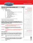
INSTALLATION
L.E.D. HALO TRIM RINGS for PASSING LAMPS
CUSTOMER SERVICE
PARTS INCLUDED
1
1
2
1
Left Black Trim Ring and L.E.D. Halo light
Right Black Trim Ring and L.E.D. Halo Light
1/2” Wide Adhesive Foam Strips
Hardware Kit Including
8
Female T-Tap Connectors
8
Male Spades
3
4” Black Nylon Cable Ties
2
M3 Custom Nuts
2
M3 Phillips Pan Head Screws
1
Dielectric Grease Pack
1
Installation Instructions
Please read and understand entire instructions before starting installation.
THANK YOU FOR CHOOSING KϋRYAKYN!
IN ORDER TO PROTECT YOU AND OTHERS FROM POSSIBLE INJURY AND/OR
PROPERTY DAMAGE OR LOSS, PLEASE PAY CLOSE ATTENTION TO ALL
INSTRUCTIONS, WARNINGS, CAUTIONS AND NOTICES REGARDING THE USE
AND CARE OF THIS PRODUCT.
THIS INDICATION ALERTS YOU TO THE FACT THAT
IGNORING THE CONTENTS DESCRIBED HEREIN CAN
RESULT IN POTENTIAL DEATH OR SERIOUS INJURY.
This indication alerts you to the fact that ignoring the
contents described herein may negatively affect product
performance and functionality.
IF INSTALLING THIS PRODUCT FOR ANOTHER PARTY,
PLEASE MAKE SURE THEY RECEIVE THIS COPY OF THE
INSTALLATION INSTRUCTIONS SO THEY ARE AWARE OF
THE IMPORTANT INFORMATION CONTAINED IN THEM.
TOOLS SUGGESTED
#2 Phillips Head Screwdriver, Wire Crimping Tool, Wire Cutter, Wire Stripper
STRICTLY OBSERVE THE FOLLOWING GUIDELINES IN ORDER TO USE THE
PRODUCT PROPERLY AND AVOID POTENTIALLY DANGEROUS ACCIDENTS.
STEP 1
7271
Read and understand all steps in the instructions before starting the
installation. Park the motorcycle on a hard, level surface and turn off the
ignition. Let cool.
Avoid damage to the motorcycle. Protect painted surfaces with a
soft cloth or blanket.
A factory service manual may be helpful in performing this
installation. Do not attempt to perform this installation if you are
not confident in your ability to complete all of the steps in the
procedure; consult a trained technician.
NOTE: Pictures shown are of chrome parts. Installation of BLACK parts will be
the same.
STEP 2
Determine the left from the right side (sitting on bike) Halo Trim Rings. The
wire will exit the Trim Ring towards the headlight. PIC 1
7271-21HD-0512
-cont.-
877.370.3604 (toll free)
INSTALLATION QUESTIONS
[email protected]
or call 715.247.2983
LIMITED WARRANTY
Küryakyn warrants that any Küryakyn products
sold hereunder, shall be free of defects in
materials and workmanship for a period of one
(1) year from the date of purchase by the
consumer excepting the following provisions:
● Küryakyn shall have no obligation in the event
the customer is unable to provide a receipt
showing the date the customer purchased the
product(s).
●The product must be properly installed,
maintained and operated under
normal conditions.
●Küryakyn makes no warranty, expressed or
implied, with respect to any gold plated
products.
●Küryakyn shall not be liable for any
consequential and incidental damages, including
labor and paint, resulting from failure of a
Küryakyn product, failure to deliver, delay in
delivery, delivery in nonconforming condition, or
for any breech of contract or duty between
Küryakyn and a customer.
●Küryakyn products are often intended for use in
specific applications. Küryakyn makes no
warranty if a Küryakyn product is used in
applications other than intended.
●Küryakyn electrical products are warranted for
one (1) year from the date of purchase by the
consumer. L.E.D.’S contained in components of
Küryakyn products will be warranted for defects
in materials and workmanship for 3 years from
the date of purchase where as all other
components shall be warranted for one(1) year.
This includes, but is not limited to; control
modules, wiring, chrome & other components.
●Küryakyn makes no warranty of any kind in
regard to other manufacturer¹s products
distributed by Küryakyn. Küryakyn will pass on
all warranties made by the manufacturer and
where possible, will expedite the claim on behalf
of the customer, but ultimately, responsibility for
disposition of the warranty claim lies
with the manufacturer.
ABOUT OUR CATALOG
For purchasing Küryakyn® products, you
can receive a complete catalog free of charge.
Send the Proof-of-Purchase below with
your address to: Küryakyn, P.O. Box 339,
Somerset, WI 54025.
Please indicate either Accessories Catalog for
Harley-Davidson® or GL & Metric Cruisers.
Be sure to ask your local dealer about other
Küryakyn® products, the motorcycle parts and
accessories designed for riders by riders.
©2005 Küryakyn USA® All Rights
reserved.
STEP 3
Remove the stock trim ring from the Right spot lamp by removing the screw and nut from the
bottom of the ring. PIC 2 set these aside, they will not be reused. Hold on to the lamp. Once the
trim ring is removed, it can fall out.
PIC 1
STEP 4
Install the new Halo Trim Ring to the spot lamp using the included Phillips Pan
Head Screw and Custom Nut. The L.E.D. Halo Light Ring will seat next to the front
of the Trim Ring. The post on the bottom of the Light Ring will fit in the notch on
the bottom of the Trim Ring. PIC 3 When the locating pin is between the notch,
gently press the harness against the Trim Ring. PIC 4 this will help keep the
harness from being pinched between the Halo Ring and the spot lamp.
STEP 5
Tighten the Phillips Pan Screw with a #2 Phillips Head Screwdriver while you hold
the Custom Nut. As you tighten the Screw, make sure the back edge of the Trim
Ring is in the groove on the driving light housing. Gently shake the light after
tightening to ensure the Trim Ring is secure.
NOTE: If you have difficulty assembling the Halo Trim Ring and spot lamp using
RIGHT SIDE
PIC 2
the OEM backing ring, remove the Halo Trim Ring and the spot lamp from
the housing. Remove the OEM backing ring and apply one of the included
foam strips to the back of each spot lamp. PIC 5 Reinstall the lamp and
Halo Trim Ring. Foam strips may need to be trimmed for proper fit.
STEP 6
Route the wire harness from the Halo Trim Ring along the existing spot lamp
harness to the inside of the fairing or headlight cowl. Secure the harness with the
included cable ties.
STEP 7
Repeat Steps 3, 4, 5 and 6 for the left side. Proceed to the wiring section for your
model.
It is the installer’s responsibility to ensure that all of the fasteners
(including pre-assembled) are tightened before operation of the
motorcycle. Küryakyn will not issue a warranty on components lost
due to improper installation. Periodic maintenance may be required.
LEFT SIDE
REMOVE THIS SCREW AND NUT
PIC 3
POST
WIRING FOR FLST MODELS
STEP 8
Remove the left (sitting on bike) rear side of the headlight cowl as per the service
manual.
STEP 9
Locate the GRAY/BLACK stripe wire attached to the toggle switch mounted on the
left rear cowl. Install two of the included Female T-Tap Connectors to this wire.
STEP 10
Locate a ground wire. This is usually a BLACK wire. Use the wire schematic in the
service manual or a test light to confirm that you have a Ground wire. Attach two
of the included Female T-Tap Connectors to this wire.
NOTCH
PIC 4
Küryakyn recommends the use of dielectric grease on electrical
connections.
STEP 11
STEP 12
Plug the Male Spades on the RED wires in the Halo Trim Ring harnesses to the
Female T-Taps on the GRAY/BLACK stripe wire. Plug the BLACK wires from the
Halo Trim Ring harnesses to the determined Ground wire.
GENTLY PRESS HARNESS
AGAINST TRIM RING
PIC 5
Test the Halo Trim Rings and spot lamps to see if they operate with the switch
correctly. Replace the headlight cowl.
ENSURE PROPER LIGHT OPERATION BEFORE RIDING THE
MOTORCYCLE. VISIBILITY IS A MAJOR CONCERN FOR
MOTORCYCLISTS. A LIGHT MALFUNCTION COULD RESULT IN
DEATH OR SERIOUS INJURY.
APPLY FOAM
STRIP TO LAMP
Secure all wiring away from any moving parts, pinch points or extreme heat.
Küryakyn WILL NOT issue a warranty on any electrical component that fails due to
pinched, crimped, broken, abraded, melted or frayed wires.
-cont.-
L.E.D. HALO TRIM RING/SPOT LAMPS
PAGE
2
INSTALLATION
WIRING FOR FLHT MODELS
STEP 13
Remove the outer fairing as per the service manual.
STEP 14
On ‘06 and Later Models: Locate the stock turn signal connectors. The
connectors are located on the inside of the inner fairing, mounted to each inner
fairing brace. PIC 6 There will be one violet wire, one blue wire, one gray wire and
one black wire coming out of the connector. Attach a Female T-Tap Connector to
the GRAY/BLACK stripe wire on each side. Attach a Female T-Tap Connector to the
BLACK wire on each side of this harness.
PIC 6
On ‘05 and Earlier Models: Locate the GRAY/BLACK wire that operates the spot
lamps. Attach two of the included Female T-Tap Connectors to this wire. PIC 7
Locate a ground wire. This is usually a BLACK wire. Use the wire schematic in the
service manual or a test light to confirm that you have a Ground wire. Attach two
of the included Female T-Tap Connectors to this wire.
SPOT LAMP HARNESS
MOUNTED HERE ON
EACH SIDE OF INNER
FAIRING
Küryakyn recommends the use of dielectric grease on electrical
connections.
STEP 15
Plug the Male Spades on the RED wires in the Halo Trim Ring harnesses to the
Female T-Taps on the GRAY/BLACK wires. Plug the Male Spades on the BLACK
wires from the Halo Trim Ring harnesses to the Female T-Taps on the BLACK wires.
STEP 16
Test the Halo Trim Rings and spot lamps to see if they operate with the switch
correctly. Replace the outer fairing.
ENSURE PROPER LIGHT OPERATION BEFORE RIDING THE
MOTORCYCLE. VISIBILITY IS A MAJOR CONCERN FOR
MOTORCYCLISTS. A LIGHT MALFUNCTION COULD RESULT IN
DEATH OR SERIOUS INJURY.
PIC 7
SPOT LAMP HARNESS
PIC 8
Secure all wiring away from any moving parts, pinch points or extreme heat. Küryakyn WILL NOT issue a warranty on any electrical
component that fails due to pinched, crimped, broken, abraded,
melted or frayed wires.
WIRING FOR FLHR MODELS
STEP 17
Remove the headlight from the headlight shroud per the service manual.
STEP 18
Locate the GRAY/BLACK wire that operates the spot lamps. PIC 8 Attach two of
the included Female T-Tap Connectors to this wire.
STEP 19
Locate a ground wire. This is usually a BLACK wire. Use the wire schematic in the service manual
or a test light to confirm that you have a Ground wire. Attach two of the included Female T-Tap
Connectors to this wire.
SPOT LAMP HARNESS
Küryakyn recommends the use of dielectric grease on electrical connections.
STEP 20
Plug the Male Spades on the RED wires in the Halo Trim Ring harnesses to the
Female T-Taps on the GRAY/BLACK stripe wire. Plug the BLACK wires from the
Halo Trim Ring harnesses to the determined Ground wire.
STEP 21
Test the Halo Trim Rings and spot lamps to see if they operate with the switch
correctly. Replace the headlight.
ENSURE PROPER LIGHT OPERATION BEFORE RIDING THE MOTORCYCLE.
VISIBILITY IS A MAJOR CONCERN FOR MOTORCYCLISTS. A LIGHT
MALFUNCTION COULD RESULT IN DEATH OR SERIOUS INJURY.
It is the installer’s responsibility to ensure that all of the fasteners (including
pre-assembled) are tightened before operation of the motorcycle. Küryakyn will not
issue a warranty on components lost due to improper installation. Periodic
maintenance may be required.
Ride On!
L.E.D. HALO TRIM RING/SPOT LAMPS
PAGE
3
INSTALLATION