1
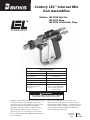
Century LEL™ Internal Mix Gun Assemblies Models: 102-3800 Wet Out 102-3825 Chop 102-3835 Filled Resin Chop SPECIFICATIONS Catalyst inlet size: 7/16 – 20 JIC (#4) Resin inlet size: 1/4" or 3/8" NPS (m) Solvent inlet size: 1/4" NPS (m) Chopper air inlet size: 1/4" NPS (m) Maximum fluid pressure: 3500 psi [241 bar] Weight: 2.4 lbs [1.1 kg] Anodized Aluminum, Stainless Steel, UHMW, PTFE, Silicone Rubber, EPR, Nylon, Tungsten Carbide Wetted parts materials of construction: ! WARNING Before using the Century LEL gun, be sure to read and understand all warnings included in this part sheet. The Binks Century LEL (Low Emission Laminator) guns are high-performance “nonatomizing” internal-mix application devices for the application of polyester and other catalyzed resins. All Binks branded FRP applicators indicated as “LEL” or “LEL technology,” utilize impinging fluid streams at low pressure to generate low velocity resin and gel-coat fans and are therefore defined by the EPA (NESHAP 40 CFR part 63) as non-atomizing. If the Century LEL gun is used according to the instructions listed in this part sheet it will provide the user with higher transfer efficiency, a cleaner work space, and help enable MACT compliance by allowing the use of non-atomized mechanical application UEF factors when calculating plant emissions. Replaces Part Sheet 2914 Part Sheet 77-2914R In this part sheet, the words WARNING, CAUTION and NOTE are used to emphasize important safety information as follows: ! WARNING ! Hazards or unsafe practices which could result in severe personal injury, death or substantial property damage. ! NOTE Caution Hazards or unsafe practices which could result in minor personal injury, product or property damage. Important installation, operation or maintenance information. Warning Read the following warnings before using this equipment. Read the Manual Before operating finishing equipment, read and understand all safety, operation and maintenance information provided in the operation manual. Plural Component Materials Hazard Because of the vast number of chemicals that could be used and their varying chemical reactions, the buyer and user of this equipment must determine all facts relating to the materials used, including any of the potential hazards involved. Wear Safety Glasses Failure to wear safety glasses with side shields could result in serious eye injury or blindness. Noise Hazard You may be injured by loud noise. Hearing protection may be required when using this equipment. De-energize, DEPRESSURIZE, Disconnect and Lock Out All Power Sources During Maintenance Failure to De-energize, disconnect and lock out all power supplies before performing equipment maintenance could cause serious injury or death. Fire and Explosion Hazard Improper equipment grounding, poor ventilation, open flame or sparks can cause hazardous conditions and result in fire or explosion and serious injury. Operator Training All personnel must be trained before operating finishing equipment. Pinch Point Hazard Moving parts can crush and cut. Pinch points are basically any areas where there are moving parts. Equipment Misuse Hazard Equipment misuse can cause the equipment to rupture, malfunction, or start unexpectedly and result in serious injury. Know Where and How to Shut Off the Equipment in Case of an Emergency Keep Equipment Guards in Place Do not operate the equipment if the safety devices have been removed. Pressure Relief Procedure Always follow the pressure relief procedure in the equipment instruction manual. High Pressure Consideration High pressure can cause serious injury. Relieve all pressure before servicing. Spray from the spray gun, hose leaks, or ruptured components can inject fluid into your body and cause extremely serious injury. Projectile Hazard You may be injured by venting liquids or gases that are released under pressure, or flying debris. Static Charge Fluid may develop a static charge that must be dissipated through proper grounding of the equipment, objects to be sprayed and all other electrically conductive objects in the dispensing area. Improper grounding or sparks can cause a hazardous condition and result in fire, explosion or electric shock and other serious injury. Toxic Fluid & Fumes Hazardous fluid or toxic fumes can cause serious injury or death if splashed in the eyes or on the skin, inhaled, injected or swallowed. LEARN and KNOW the specific hazards or the fluids you are using. CA PROP 65 PROP 65 WARNING WARNING: This product contains chemicals known to the State of California to cause cancer and birth defects or other reproductive harm. It is the respoNsibility of the employer to provide this information to the operator of the equipment. 2 FOR FURTHER SAFETY INFORMATION REGARDING BINKS AND DEVILBISS EQUIPMENT, SEE THE GENERAL EQUIPMENT SAFETY BOOKLET (77-5300). ! Warning when using Binks equipment with Methyl Ethyl Ketone Peroxide in Plasticizer OBSERVE the following precautions corrosive to the eyes – may cause blindness. may be fatal if swallowed. strong irritant. contamination or heat may lead to fire or explosive decomposition. combustible. Do not handle or use until safety precautions concerning Methyl Ethyl Ketone Peroxides in the Manufacturer’s literature have been read and understood. Contact with foreign materials, especially strong mineral acids, metals (including certain equipment and containers) or metal salts, or exposure to heat above 135° F (57° C) may lead to violent decomposition, releasing flammable vapors which may self-ignite. Do not get into eyes or on skin or clothing. Wear eye and skin protection when handling. Avoid breathing mist. Use with adequate ventilation. Store only it in the original closed container. Wash hands thoroughly after handling. Protect from direct sunlight, heat, sparks and other sources of ignition. Prevent contamination with foreign materials. Do not add to hot materials. FIRST AID EYES Wash immediately (seconds count) with water and continue washing for at least 15 minutes. Obtain medical attention. SKIN Wash with soap and water. Remove contaminated clothes and shoes and again wash thoroughly with soap and water. SWALLOWING Administer large quantities of milk or water. Obtain immediate medical attention for lavage. To maintain the chemical activity store below 100° F (38° C). In case of fire, use water spray, foam or dry chemical. In case of spill or leak, absorb or blend with inert, non-combustible material. Put in suitable container. Dispose of immediately in accordance with federal, state and local regulations. Do not reuse container as some of the original hazardous contents may still be present. Follow the above precautions in handling. READ & UNDERSTAND THE MATERIAL SAFETY DATA SHEET FROM MATERIAL SUPPLIER ! Warning Binks Century "LEL" GUNS are constructed with components of aluminum alloy and SHOULD NOT be used with any Halogenated Hydrocarbon solvents. Halogenated hydrocarbon solvents can cause an explosion when in contact with aluminum components of a pressurized or closed fluid system (pumps, heaters, filters, etc.) The same possibility of an explosion is possible with the galvanized coatings in pressure tanks. The possibility of a non-flammable explosion increases greatly at high operating temperatures. The explosion could be of sufficient strength to cause bodily injury, death, and substantial property damage. Cleaning agents, coatings, or adhesives may contain halogenated hydrocarbon solvents. Check with your solvent and paint supplier. If you are now using a Halogenated Hydrocarbon Solvent in a pressurized fluid system with aluminum components or galvanized wetted parts, the following steps should be taken immediately: 1. Remove all pressure; drain and disconnect the entire system. 2. Inspect and replace all corroded parts. 3. Contact your solvent supplier for a non-halogenated solvent to flush and clean the system of all residues. Halogenated Solvents are defined as any hydrocarbon solvent containing any of the following elements: Chlorine “Chloro” (Cl) Bromine“Bromo” (Br) Fluorine“Fluoro” (F) Iodine“Iodo” (I) Of those listed, the Chlorinated Solvents will most likely be the type used as a cleaning agent or solvent in an adhesive or coating. The most common are: Methylene Chloride 1,1,1, Trichlorethane Perchlorethylene Although stabilizers have been added to some of the solvents to reduce their corrosive effect, we are aware of none that will prevent these solvents from reacting under all conditions with aluminum components or galvanized coatings. Previous use of the solvents under pressurized conditions, without incident, does not necessarily indicate that it can be considered safe. 3 CENTURY LEL™ INTERNAL MIX GUN ASSEMBLIES ITEM NO. 1 2 3 4 5 6 7 8 9 10 11 12 13 14a 14b 15 16 17 18 19 20 21 22 23 24 25 26 27 28 29 30 31 32 33 34 35 36 37 38 39 40 41 42 43 44 45 46 47 PART No. 102-3809 102-3813 102-3815 20-5919 102-3812 102-3814 20-6856 102-3839 102-3779 102-3802 102-3844 102-3831 102-2447 102-2446 102-2505 102-3801 102-2404 102-3820 72-792 20-5051 102-2448 102-2410 102-2420 102-3833 102-2621 102-3335 102-2427 54-3504 54-1020 102-2470 102-2465 20-3111 102-2467 102-3834 102-3836 102-2408 102-3608 102-2435 102-2478 82-126 102-2402 102-2489 54-714 20-6295 102-3845 102-3837 20-6515 DESCRIPTION 102-3800-1 102-3800-2 102-3825 102-3835 1 1 REF 1 1 1 1 1 1 1 1 1 1 1 1 1 1 1 1 2 1 1 1 1 1 1 1 1 1 1 1 1 1 1 1 1 REF 1 1 REF 1 1 1 1 1 1 1 1 1 1 1 1 1 1 1 1 2 1 1 1 1 1 1 1 1 1 1 1 1 1 1 1 1 REF 1 REF 1 1 1 1 1 1 1 1 1 1 1 1 1 1 1 1 1 1 1 1 1 1 1 1 1 1 1 1 1 1 1 REF 1 REF 1 1 1 1 1 1 1 1 1 1 1 1 1 1 1 1 1 1 1 1 1 1 1 1 1 1 1 1 1 1 1 REF LEL NOZZLE RETAINING RING TIP RETAINER, 1 INCH TIP RETAINER, 2 INCH CENTURY LEL NOZZLE •▲ O-RING STATIC MIXER HOUSING, 1 INCH STATIC MIXER HOUSING, 2 INCH •▲ O-RING 1/4" DIA STATIC MIXER ELEMENT, 1 INCH 1/4" DIA STATIC MIXER ELEMENT, 2 INCH CATALYST VALVE ASSEMBLY CATALYST VALVE ASSEMBLY (FILLED) HEAD INSERT +▲ RESIN SEAT, PLASTIC RESIN SEAT, CARBIDE •▲ HEAD INSERT SEAL HEAD MACHINING GUARD STUD FLUSH VALVE ASSEMBLY DM NIPPLE, 1/8 NPT X 1/4 NPT SS PIPE PLUG, 1/16 NPT SS +▲ CATALYST SEAT ▲ RESIN NEEDLE ASSEMBLY ▲ CATALYST NEEDLE ASSEMBLY HANDLE PLUG CHOPPER VALVE ASSEMBLY SEAL ▲ HEAD GASKET PLUG TRIGGER STUD, LONG CHOPPER TRIGGER ASSEMBLY TRIGGER STUD, SHORT PIPE PLUG, 1/8 NPT SS CHOPPER AIR INLET FITTING PLUG CATALYST INLET & FILTER ASSEMBLY •▲ RETAINER GASKET HEAD BOLT RESIN INLET TUBE, 1/4" NPS RESIN INLET TUBE, 3/8" NPS TRIGGER SCREW CENTURY GUN HANDLE MACHINING CENTURY GUN TRIGGER PLUG BUTTON HEAD SCREW GUARD ASSEMBLY NIGHT PLUG ASSEMBLY O-RING (included with 102-3837) • Parts are included in 106-1267 Soft seal kit. + Parts are included in 106-1174 Soft seat kit. ▲ Parts are included in 106-1269 Rebuild kit. 21 16 GL 10 11 20 TS 19 TS 15 7 46 3 47 18 14 17 13 PJ 9 8 6 5 4 2 4 1 PJ 12 GL GL Additional items not shown: GL 102-2510 3/8" Dowel pin 102-2511 1/4" Dowel pin PJ TS 35 31 30 TS TS 29 TS 34 37 36 PJ 38 33 32 27 26 25 39 PJ TS 23 24 TS 40 24 28 22 41 PJ 42 43 TS MAINTENANCE SYMBOLS: # PJ TS GL = ITEM NUMBER 45 44 TS = PETROLEUM JELLY = THREAD SEALANT PTFE tape = GUN LUBE SSL-10 Recommended tool list: Open ended wrenches: 3/16, 7/32, 5/16, 3/8, 7/16, 9/16, 11/16 Hex key wrenches: 3/16, 1/4, 5/32 Flat screwdrivers Awl or other pointed instrument 5 TS CENTURY LEL™ INTERNAL MIX CHOPPER GUN ASSEMBLIES TS 5 4 3 7 2 10 14 1 INCLUDED WITH ITEM 1 6 8 9 11 GL 12 GL ITEM NO. 1 1 2 3 4 5 6 7 8 9 10 11 12 13 14 PART No. DESCRIPTION 102-3825 102-3835 102-2661 20-6154 20-1374 201-510 102-3839 102-3779 20-6856 •▲ 102-3812 102-3814 20-5919 •▲ 102-3813 102-3815 CHOPPER GUN SUB-ASSEMBLY CHOPPER GUN SUB-ASSEMBLY, FILLED RESIN CHOPPER MOUNT BRACKET FLAT HEAD SCREW FLAT HEAD SCREW CHOPPER ASSEMBLY STATIC MIXER ELEMENT, 1 INCH STATIC MIXER ELEMENT, 2 INCH O-RING STATIC MIXER HOUSING, 1 INCH STATIC MIXER HOUSING, 2 INCH O-RING CENTURY LEL NOZZLE TIP RETAINER, 1 INCH TIP RETAINER, 2 INCH • Parts are included in 106-1267 Soft seal kit. ▲ Parts are included in 106-1269 Rebuild kit. 6 PJ 13 102-3825-1 102-3825-2 102-3835-1 102-3835-2 1 1 1 1 1 1 1 1 1 REF 1 - 1 1 1 1 1 1 1 1 1 REF 1 1 1 1 1 1 1 1 1 1 REF 1 - 1 1 1 1 1 1 1 1 1 REF 1 Part Sheet 77-2475 SUBASSEMBLIES 22f 22d 102-2410 RESIN NEEDLE ASSEMBLY 22c Item 22 22e When ordering, please specify Part No. 22b 22a ITEM NO. 22a 22b 22c 22d 22e 22f PART NO. 102-2411 • 102-2412 102-2419 102-2428 102-2613 52-487 DESCRIPTION QTY. PACKING..............................................1 RESIN NEEDLE SUB-ASM.....................1 RESIN PACKING NUT...........................1 CONVEX NUT (5/16 HEX)....................1 SPRING.................................................1 LOCKNUT.............................................1 • Parts are included in 106-1267 Soft seal kit. 102-2410 is also included within 106-1269 Rebuild kit. 102-2420 CATALYST NEEDLE ASSEMBLY Item 23 When ordering, please specify Part No. ITEM NO. 23a 23b 23e 23d 23c 23f 23a 23b 23c 23d 23e 23f PART NO. 102-2421 • 102-2422 102-2428 102-2429 102-2613 52-487 DESCRIPTION QTY. PACKING..............................................1 CATALYST NEEDLE SUB-ASM..............1 CONVEX NUT (5/16 HEX)....................1 CATALYST PACKING NUT....................1 SPRING.................................................1 LOCKNUT.............................................1 • Parts are included in 106-1267 Soft seal kit. 102-2420 is also included within 106-1269 Rebuild kit. 102-2621 CHOPPER VALVE ASSEMBLY 25e 25a Item 25 25c When ordering, please specify Part No. 25b ITEM NO. 25g 25d 25h 25f 25a 25b 25c 25d 25e 25f 25g 25h PART NO. 102-2464 102-2649 102-2651 102-2652 20-6502 20-6631 20-6663 52-487 DESCRIPTION QTY. VALVE...................................................1 CHOPPER VALVE SPRING....................1 CHOPPER VALVE BODY.......................1 VALVE STEM........................................1 ROUND HEAD SCREW.........................1 FILLISTER HEAD SCREW......................1 O-RING.................................................1 LOCKNUT.............................................1 7 SUBASSEMBLIES 102-2470 CHOPPER TRIGGER ASSEMBLY 30a Item 30 When ordering, please specify Part No. 30b 30d ITEM NO. 30e 30a 30b 30c 30d 30e 30c PART NO. 102-2471 102-2472 102-2473 102-2474 102-2475 DESCRIPTION QTY. CHOPPER TRIGGER..............................1 ON/OFF SELECTOR...............................1 RETAINER SCREW................................1 LOW FRICTION WASHER.....................1 WAVE WASHER...................................1 11h 102-3802 CATALYST VALVE ASSEMBLY 11f 11e Item 11 11d When ordering, please specify Part No. 11c ITEM NO. 11b 11a 11g Note orientation of items 11h. 11a 11b 11c 11d 11e 11f 11g 11h PART NO. DESCRIPTION QTY. 102-3804 VALVE BODY PLUG.............................1 20-6854 •▲O-RING.................................................1 102-3806 SPRING RETAINER................................1 102-3807 SPRING.................................................1 102-3803 VALVE BODY.......................................1 102-3805 CATALYST VALVE PIN..........................1 20-6855 •▲O-RING.................................................2 102-3808 IMPINGEMENT BAFFLE.......................2 • Parts are included in 106-1267 Soft seal kit. ▲ Parts are included in 106-1269 Rebuild kit. 102-3820 FLUSH VALVE ASSEMBLY 18f Item 18 18e When ordering, please specify Part No. 18c 18h 18a 18d 18g 18b ITEM NO. PART NO. DESCRIPTION • Parts are included in 106-1268 Flush valve repair kit. 8 QTY. 18a 102-3821 VALVE BODY.......................................1 18b 102-3822 BUTTON...............................................1 18c 207-11547• GASKET................................................1 18d 207-12201 SPRING.................................................1 18e 207-12204 STEM....................................................1 18f 237-66 • O-RING.................................................1 18g 237-88 • O-RING.................................................1 18h 237-91 • O-RING.................................................1 SUBASSEMBLIES 102-3836 CATALYST INLET/FILTER ASSEMBLY 35c Item 35 35d When ordering, please specify Part No. 35b 35a 35e ITEM NO. 35a 35b 35c 35d 35e PART NO. DESCRIPTION QTY. 54-1263 CATALYST STRAINER SUPPORT...........1 102-2181 •▲CATALYST INLET SCREEN....................1 102-2442 CATALYST INLET TUBE........................1 237-91 •▲O-RING.................................................1 207-12343 JIC #4 ADAPTER...................................1 • Parts are included in 106-1175 Catalyst filter repair kit. ▲ Parts are included in 106-1269 Rebuild kit. JIC #3 Adapter: 207-12212 1/4" NPS (m) Adapter: 102-2441 102-3844 CATALYST VALVE ASSEMBLY, FILLED RESIN 12f 12e Item12 12d 12c When ordering, please specify Part No. 12b 12a ITEM NO. 12a 12b 12c 12d 12e 12f 12g 12g PART NO. DESCRIPTION QTY. 102-3804 VALVE BODY PLUG.............................1 20-6854 •▲O-RING.................................................1 102-3806 SPRING RETAINER................................1 102-3807 SPRING.................................................1 102-3838 VALVE BODY.......................................1 102-3805 CATALYST VALVE PIN..........................1 20-6855 •▲O-RING.................................................2 • Parts are included in 106-1267 Soft seal kit. ▲ Parts are included in 106-1269 Rebuild kit. 106-1268 FLUSH VALVE REPAIR KIT 106-1267 SOFT SEAL KIT PART NO. DESCRIPTION QTY. 102-2408 RETAINER GASKET.............. 1 102-2411 RESIN PACKING GUIDE....... 1 102-2421 CATALYST PACKING............ 1 102-2427 HEAD GASKET..................... 1 102-2505 HEAD ASSEMBLY SEAL....... 1 106-1268 FLUSH VALVE REPAIR KIT... 1 20-5919O-RING................................. 1 20-6854O-RING................................. 1 20-6855O-RING................................. 2 20-6856O-RING................................. 1 106-1269 REBUILD KIT PART NO. DESCRIPTION QTY. PART NO. DESCRIPTION 207-11547GASKET.............. 1 237-66O-RING............... 1 237-88O-RING............... 1 237-91O-RING............... 1 20-5919O-RING................................ 1 20-6854O-RING................................ 1 20-6855O-RING................................ 2 20-6856O-RING................................ 1 102-2181SCREEN................................ 1 102-2408 RETAINER GASKET.............. 1 102-2410 RESIN NEEDLE ASSLY.......... 1 102-2420 CATALYST NEEDLE ASSY.... 1 102-2427 HEAD GASKET.................... 1 102-2447 RESIN SEAT.......................... 1 102-2448 CATALYST SEAT................... 1 102-2505SEAL.................................... 1 106-1268 FLUSH VALVE REPAIR KIT... 1 237-91O-RING................................ 1 QTY. 9 BINKS CENTURY LEL™ INTERNAL MIX GUN SUGGESTED SPARE PARTS AND KITS Part No. Description Qty. per Pkg. Fluid Tip (size determined by application) 118-8XXYY XX = orifice size in thousandths of inch YY = orifice angle 1 106-1267 Soft Seal Kit (o-rings & gaskets) See description page 9 106-1268 Flush valve repair kit See description page 9 106-1269 Rebuild kit See description page 9 106-1174 Soft seat kit 10 resin, 5 catalyst 106-1175 Catalyst filter repair kit (o-ring, screen) 5 sets 102-3839-K6 1" static mixer elements 6 102-3779-K6 2" static mixer elements 6 Most o-rings and seals are available in multi-packs Part No. Description Qty. per Pkg. 102-2408-K5 RETAINER GASKET 5 102-2427-K5 HEAD GASKET 5 102-2505-K5 HEAD INSERT SEAL 5 102-3335-K5 SEAL 5 20-6854-K5 O-RING (SILICONE) 5 20-6855-K10 O-RING (SILICONE) 10 20-6856-K5 O-RING (SILICONE) 5 20-5919-K5 O-RING (EPR) 5 207-11547-K5 GASKET 5 237-66-K5 O-RING (EPR) 5 20-6515-K10 O-RING (EPR) 10 237-88-K5 O-RING (SILICONE) 5 237-91-K5 O-RING (SILICONE) 5 102-2411-K5 RESIN NEEDLE PACKING 5 102-2421-K5 CATALYST NEEDLE PACKING 5 20-6663-K5 O-RING (BUNA) 5 STATIC MIXER HOUSING KITS Part No. Description KITS CONTAIN 102-3840 1" STATIC MIX KIT 102-3841 2" STATIC MIX KIT STATIC MIXER HOUSING, TIP RETAINER, STATIC MIXER, O-RINGS MIXER HOUSING SUB-ASSEMBLIES 10 Part No. Description 102-3842 1" MIXER HOUSING ASSEMBLY 102-3843 2" MIXER HOUSING ASSEMBLY SUB-ASSEMBLIES CONTAIN STATIC MIXER HOUSING, O-RINGS CENTURY LEL™ INTERNAL MIX GUN ASSEMBLIES Your new Binks Century LEL gun will give you excellent performance as long as it is handled properly. Read over these sections before operating the gun. NOTE Whenever the gun is not in operation set the trigger lock by rotating the trigger (42) as far forward as it will go and then rotating the locking block in its upward orientation. SET-UP INSTRUCTIONS: 1. Connect the air hose to the cutter air inlet fitting (33) if a fiberglass chopper is being used. Disregard this step if a cutter is not being used. 2. Connect the resin hose to the resin inlet fitting (38 or 39) and securely tighten. 3. Connect the high pressure catalyst hose to the catalyst inlet/ filter housing (35) and securely tighten. 4. Connect the solvent flush hose to the male connector (19) and securely tighten. REAR VIEW OF GUN HANDLE ResIn Inlet (1/4" or 3/8" NPS) Catalyst Inlet (7/16 - 20 JIC) 3. Prime the catalyst pump. A. Binks Unison Adjust the catalyst percentage using the catalyst adjustment knob on the end of the yoke. Turn the knob at the front of the yoke assembly in a circular pattern causing the pump rod to reciprocate. Holding the gun over a suitable container, pull the trigger of the gun to relieve trapped air and prime the system with catalyst. Continue the motion of turning the knob in conjunction with triggering the gun until catalyst is seen coming out from the front of the gun head (16). At this time, all trapped air is purged and the catalyst is primed. B. Binks Super Slave 1. H olding the gun over a suitable container, pull the gun trigger open and begin to manually reciprocate the catalyst pump rod to prime catalyst through the system and relieve trapped air. Continue this motion until catalyst can be seen coming out of the gun head (16). At this time, all trapped air is purged and the catalyst is primed. 2. S olvent flush the remaining catalyst within the gun head (16). 3. I MPORTANT: Install the night plug assembly (46) and retaining ring (1) at this time. RESIN PRIMING AND SET-UP: Solvent Inlet (1/4" NPS) Chopper Air Inlet (1/4" NPS) 102-3825 & 102-3835 Only SOLVENT FLUSH SET-UP: 1. Turn all ball valves to the closed position. 2. Connect the main air line to the system’s main air inlet. 3. Fill the solvent flush tank with a suitable solvent as recommended by your chemical supplier for your application. 4. Securely fasten the pressure tank cover and open the solvent flush “air” ball valve, and slowly adjust the solvent tank air regulator to 40 psi (2.7 bar). Open the solvent ball valve at the tank, supplying solvent to the gun. 5. Remove the tip retainer, mixer housing, catalyst valve assembly, and related parts (items 1 through 12) from the gun head. Pointing the gun down and into a container, test flush by pushing the small button on the flush valve assembly (18). Solvent will flow through the gun head. CATALYST PRIMING AND SET-UP: 1. Disconnect the catalyst pump from the resin pump. A.Binks Unison pump Disengage the pins from the hub by pulling out the yoke and drive assembly. B. Binks Super Slave pump assembly Remove the pin from the “percentage” lever/cross bar that connects the catalyst pump rod-end bearing. 2. Attach the catalyst supply hose. Attach the catalyst pick-up and cap assembly to the catalyst bottle. 1. The catalyst pump at this time must still be disengaged / disconnected from the resin pump. 2. Connect siphon/pick-up tubes to the resin pump, and insert the tube into the resin drum. 3. Adjust the resin pump air regulator to approximately 25 to 30 psi (2 bar), and slowly open the regulator ball valve. The pump will begin to cycle. As the pump is cycling, point the gun head into a grounded container and pull the gun trigger. Hold the gun trigger in the open position until resin comes out of the gun head (16). 4. Solvent flush the gun. 5. Engage the trigger lock. 6. Connect the catalyst pump. 7. At this time, the system is primed. Set the resin pump air regulator to approximately 40-45 psi (3 bar). OPERATION: 1. Ensure the trigger lock is engaged. Install the catalyst valve assembly, the mixer housing, tip, tip retainer, and related parts (items 1-12) onto the gun head. 2. Disengage the trigger lock. Pull trigger to observe spray pattern. A very narrow pattern or very heavy “tails” (see illustration) normally indicate too low fluid pressure for the tip being used. Gradually increase the fluid pressure until tails diminish. If increasing the fluid pressure results in too high flow, try a smaller tip. 3. Too high fluid pressure (see illustration) will result in overspray, misting of the resin and increased emissions, possibly resulting in non-compliant operation. Decrease the fluid pressure until correct pattern is observed. Fluid pressure too low Fluid pressure too high 11 CENTURY LEL™ INTERNAL MIX GUN ASSEMBLIES 4. Proper distance between gun and mold is 12-18 inches (30-45 cm). Longer distances result in uncontrolled spray and higher emissions. 5. LEL guns are either on or off. You cannot feather with LEL guns as you can with air-atomizing guns. 6. The material deposited on the mold should always be even, and each stroke should overlap the previous stroke by half or less. Uniform coverage is best accomplished by “crosshatching” strokes. CHOPPER TRIGGER OPERATION (102-3825 & 102-3835) The Century LEL gun is equipped with a special chopper trigger (30). This device allows simple on/off capabilities plus the ability to run/load the chopper without triggering the gun at all. To set the chopper trigger to its “on” position rotate the on/off selector (30b) as far clockwise as it will go. To set the chopper trigger to its “off” position simply rotate the on/off selector as far counterclockwise as it will go. To run the chopper without triggering the gun and, with the gun in your right hand, set the on/off selector to “on”, place your right index finger on the trigger pad of the chopper trigger sub-assembly (30a) and pull back on the chopper trigger until the chopper air valve (25) is engaged. SHUT-DOWN: 1. Shut off air at the system’s main air inlet ball valve. 2. Relieve catalyst pressure by opening the catalyst relief valve, located on the catalyst manifold block or the catalyst pump. NOTE Located at the Binks Unison catalyst manifold is the catalyst pressure gauge and relief valve, (the Binks Super Slave catalyst pressure gauge and relief valve is located on the catalyst pump). The catalyst relief valve is factory set and should not be altered. The catalyst relief valves can vent pressure manually by pulling down on the black handle. 3. Relieve resin pressure by opening the by-pass ball valve located at the resin pump or filter. 4. Engage trigger lock to prevent accidental trigger actuation. 5. Thoroughly flush solvent through the gun head, mixer housing, and tip. 6. Remove mixer housing with related parts. Remove spray tip and tip retainer from the mixer housing. Remove the static mixer element (8) from the mixer housing (4). Thoroughly clean parts. 7. Remove catalyst mixing valve (11 or 12) by gently prying it away from the gun head with a screwdriver blade. Rinse valve with solvent. 8. Install night plug (46) into the gun head (16). Secure night plug with retaining ring (1). 9. Hang the gun in a head-down position for storage overnight or longer. 10. IMPORTANT: do not allow parts to soak overnight in solvent as o-rings will swell. When re-installing parts be sure to lubricate o-rings with Binks Gunners Mate or DeVilbiss SSL10 lubricants. 12 GENERAL MAINTENANCE For Binks Super Slave units see part sheet 77-2485 for start-up, shut-down details. For Binks Unison units see part sheet 77-2800 for start-up, shut-down details. DAILY INSPECTION 1.Check the fluid needles (22, 23) for signs of material leakage. If leaks are present tighten fluid packing nuts until leakage stops. If leak does not stop replace the needle packing or needle. 2.Inspect the o-rings (5, 8, 11h, 12g) for wear or damage and replace if necessary. 3.Inspect system filters for build-up and clean if necessary. CLEANING THE LEL NOZZLE 1.Lock the trigger (42) by rotating the locking block (45) in its upward position. 2.Shut off pumps and air supply. 3.Release fluid pressure in entire system. 4.Unscrew the LEL nozzle retaining ring (1) and remove the tip retainer (2 or 3), and then the Century LEL nozzle (4). 5.Submerge the nozzle in solvent to remove any dry or hardened material. 6.Blow air through tip from front to back to remove any stuck particles. Hold tip to light to inspect orifice to verify it is clear. CATALYST INLET & FILTER ASSEMBLY 1.Shut off pumps and air supply. 2.Bleed pressure from the entire system. 3.Remove the catalyst hose from the catalyst inlet & filter assembly (35) on the gun. 4.Using a 9/16" wrench and a 7/16" wrench unscrew the material inlet adapter (35e) from the catalyst inlet tube (35c), revealing the catalyst inlet screen (35b). 5.Inspect the screen for build-up or damage. If necessary, unscrew the catalyst strainer support (35a) with your fingers and slide the catalyst inlet screen off, and clean or replace it. 6.Inspect the o-ring (35d) on the catalyst inlet tube for any cuts or tears and replace if necessary. 7.Reassemble in reverse order. OVERNIGHT SHUT-DOWN 1.Shut off pumping equipment (with the piston in its down position) and air supply. 2.Bleed pressure from entire system. 3.Remove the LEL nozzle retaining ring (1) and remove items 2 through 12. 4.Wipe off face of the gun head with a solvent-dampened rag. 5.Place the night plug assembly (46), o-ring end first, into the gun head. In many cases, lubricant will provide protection for o-rings and head during shutdown. Petroleum jelly placed in the head insert (13) helps keep residual resin from drying out. 6.Screw the LEL nozzle retaining ring back onto the gun head snugly against the night plug assembly. Do not over-tighten. 7.Clean the Century LEL nozzle (see above). Be sure to also clean out the static mixer housing (6 or 7), rinse the static mixer element (9 or 10), and flush the catalyst valve assembly (11 or 12). Inspect the o-rings for any signs of wear or damage, replace if necessary. CENTURY LEL™ INTERNAL MIX GUN ASSEMBLIES REPLACEMENT OF WORN PARTS ! WARNING Do not disassemble or work on the Binks Century LEL gun without first doing the following: 1.Shut off the fluid pumps and air supply. 2.Release the fluid pressure in the gun and the entire system. 3. Remove the gun from fluid hoses. If you do not follow these steps you may injure yourself and/or nearby personnel. REPLACING THE CATALYST NEEDLE PACKING 1.Remove the button head screw (44) that retains the guard assembly (45) by using a 3/16" Allen wrench; remove the guard assembly. 2.Using two standard screwdrivers, remove the trigger stud (29 or 31), the trigger screw (40), the trigger (42), and the chopper trigger assembly (30), if applicable. 3.Unscrew the catalyst packing nut (23d) with a 3/8" wrench and pull the catalyst needle assembly (23) straight back until it comes out of the gun head. Be sure to pull the needle straight out without bending it up or down, or side to side as this will damage the needle. 4.Clean the needle assembly so that you may be able to clearly identify the packing (23a). 5.The packing is the only non-metal piece of the needle assembly and is white in color. Note its location and orientation on the wire of the needle. Cut the worn packing away with a sharp knife being sure not to scratch or deform any nearby parts. 6.Carefully spread the new packing apart, about 3/64" at the edge (this can be done easily with an X-acto type knife) and press the packing onto the wire of the needle assembly in the same location and orientation as noted in step 5. Gently squeeze the packing closed with fingers. 7.Slide the packing forward and back with your fingers to assure a proper fit onto the wire. 8.Reassemble in reverse order. NOTE The cone face of the packing should point towards the tip of the needle assembly. REPLACING THE CATALYST SEAT 1.Remove the button head screw (44) that retains the guard assembly (45) by using a 3/16" Allen wrench; remove the guard assembly. 2.Using two standard screwdrivers, remove the trigger stud (29 or 31), the trigger screw (40), the trigger (42), and the chopper trigger assembly (30), if applicable. 3.Using a 3/8" wrench or socket, remove the head bolt (37). 4.Slide the gun head (16) as far forward as it will go with your hands. Do not use excessive force. 5.Unscrew the catalyst packing nut (23d) with a 3/8" wrench and pull the catalyst needle assembly (23) straight back until it comes out of the gun head. Be sure to pull the needle straight out without bending it up or down, or side to side as this will cause the needle damage. 6.Use a #6 or #8 self-drilling wood screw and screw it into the catalyst seat (21) until the screw threads are fully engaged in the seat material. Pull the screw with pliers to remove the seat from the gun head. Ensure that you do not nick or scratch the walls of the hole. Once the seat is removed, discard it as it is no longer usable. 7.Put the new catalyst seat into the hole of the gun head that the catalyst needle assembly came out of. The small end of the catalyst seat must go in first. The seat should drop down into the gun head. 8.The seat now needs to be pressed into place, such that a tight fit is created between the catalyst seat and the walls of the gun head that retain it. Use a 1/4" diameter dowel (102-2511) to press the seat tight. Be careful not to scratch the walls of the gun head. A drill press or arbor press is recommended for this operation. 9.Reassemble in reverse order. REPLACING THE RESIN SEAT 1.Remove the LEL nozzle retaining ring (1) and then remove items 2 through 12 from the gun head. 2.Pull the trigger (42) to unseat the resin needle (22) from the resin seat (14). Lock the trigger open by twisting the locking block on the guard assembly (45) into its up position. Using a 1/4" hex key wrench, loosen the head insert about 3 turns, leaving about 3 or so turns engagement in the gun head. 3.Insert a 1/4" dowel pin (102-2511) into the front of the head insert (13) and use it to press the seat out of the head insert. Finish removing the head insert with the 1/4" hex key wrench, allowing the seat to fall out. Remove the head assembly seal (15) and replace with a new one. 4.Now place the front of the head insert against a flat, clean surface. 5.Put the new resin seat into the tapered hole of the head insert. The small end of the resin seat must go in first. The seat now needs to be pressed in place such that a tight fit is created between the resin seat and the walls of the head insert that retain it. Use a 3/8" diameter dowel pin (102-2510) to press the seat tight. A drill press or arbor press is recommended for this operation. 6.Reassemble in reverse order. REPLACING THE RESIN NEEDLE PACKING 1.Remove the button head screw (44) that retains the guard assembly (45) by using a 3/16" Allen wrench; remove the guard assembly. 2.Using two standard screwdrivers, remove the trigger stud (29 or 31), the trigger screw (40), the trigger (42), and the chopper trigger assembly (30), if applicable. 3.Using a 3/8" wrench or socket, remove the head bolt (37). 4.Slide the gun head (16) as far forward as it will go with your hands. Do not use excessive force. 5.Unscrew the resin packing nut (22c) with a 3/8" wrench and pull the resin needle assembly (22) straight back until it comes out of the gun head. Be sure to pull the needle straight out without bending it up or down, or side to side as this will cause the needle damage. 6.Clean the needle assembly so that you may be able to clearly identify the packing (22a). 7.The packing is the only non-metal piece of the needle assembly and is white in color. Note its location and 13 CENTURY LEL™ INTERNAL MIX GUN ASSEMBLIES orientation on the wire of the needle. Cut the worn packing away with a sharp knife being sure not to scratch or deform any nearby parts. 8.Carefully spread the new packing apart, about 3/64" at the edge (this can be done easily with an X-acto type knife) and press the packing onto the wire of the needle assembly in the same location and orientation as noted in step 6. Gently squeeze the packing closed with fingers. 9.Slide the packing forward and back with your fingers to assure a proper fit onto the wire. 10. Reassemble in reverse order. NOTE The cone face of the packing should point towards the ball of the needle assembly. REPLACING THE RESIN NEEDLE ASSEMBLY 1.Repeat steps 1 through 5 from section “Replacing the Resin Needle Packing” above. 2.Replace worn needle assembly with new needle assembly. It is recommended to use petroleum jelly on the threads and around the spring before inserting into the gun head. 3.Reassemble in reverse order. REPLACING THE CATALYST NEEDLE ASSEMBLY 1.Repeat steps 1 through 3 from the section “Replacing the Catalyst Needle Packing” above. 2.Replace worn needle assembly with new needle assembly. It is recommended to use petroleum jelly on the threads and around the spring before inserting into the gun head. 3.Reassemble in reverse order. REPAIRING THE CHOPPER AIR VALVE ASSEMBLY 1.Repeat step 2 from section “Replacing the Resin Needle Packing” above. 2.Using a 9/16" wrench, remove the chopper valve assembly (25) and seal (26), from the handle (41). 3.Using a small screwdriver, remove the round head screw (25e) from the valve stem (25d). 4.Manually pull and remove the fillister head screw (25f), with its attached components from the chopper valve body (25c). 5.Remove and replace the o-ring (25g), from the valve stem. 6.Lubricate the o-ring and inside surface of the chopper valve body (25c) with petroleum jelly. 7.Reassemble the chopper air valve in the reverse order. NOTE Periodic lubrication of the chopper air valve assembly is necessary to ensure smooth operation. 14 REPAIRING THE FLUSH VALVE ASSEMBLY 1.Use an 11/16” wrench to remove the flush valve (18) from the gun head. 2.Remove the gasket (18c) from the gun head. 3.Hold the valve stem (18e) with a 5/16” wrench while unscrewing the button (18b) with a flat screwdriver. 4.Replace the valve o-rings (18f,g,h). Lubricate the o-rings with gun lube. 5.Reassemble the valve in reverse order. Test the valve assembly. It should move smoothly without sticking. 6.Place a new gasket (18c) into the gun head. Lubricate the valve threads with petroleum jelly and tighten the valve into the gun head, crushing the gasket. CLEANING / REPAIRING THE CATALYST MIXING VALVE ASSEMBLY 1.Remove the valve assembly (11 or 12) from the gun head. 2.Remove the plug (11a, 12a) from the valve body (11e, 12e). 3.Use a pair of small screwdrivers to remove the pin (11f, 12f), spring (11d, 12d), and spring retainer (11c, 12c). 4.Thoroughly clean the valve body (11e, 12e) and related parts. 5.102-3802 ASSEMBLY ONLY: the baffles (11h) may be removed for cleaning or replacement. Note the orientation of the baffles when removing and reinstalling. The baffles are press fit to the valve body and require no lubrication or adhesive. To remove, carefully pry them away from the valve body with a screwdriver. To reinstall, simply press them onto the valve body with a socket or other hollow object. 6.Replace o-rings (11b, 11g, or 12b, 12g). Lube o-rings with gun lube. 7.Reassemble valve in reverse order. NOTE The valve spring force is NOT adjustable. Different springs are necessary to change valve opening pressure. Consult your Binks representative for details. NOTES 15 WARRANTY This product is covered by Binks’ 1 Year Limited Warranty. Binks Sales and Service: www.binks.com U.S.A./Canada Customer Service 195 Internationale Blvd. Glendale Heights, IL 60139 630-237-5000 Toll Free Customer Service and Technical Support 800-992-4657 Toll Free Fax 888-246-5732 77-2914R Revisions: Trademark updates; (P2) Added Prop 65 warning; (PP4,6-9) Updated Parts Lists; (P10) Updated charts; (P16) Updated contact information. 10/12 ©2012 Binks All rights reserved. Printed in U.S.A.