1
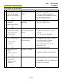
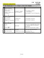
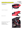
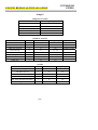
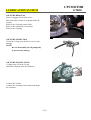
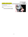
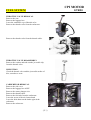
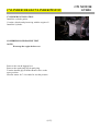
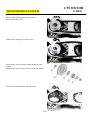
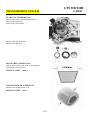
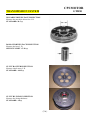
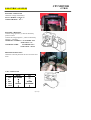
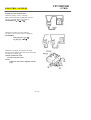
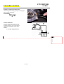
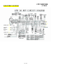
Collaboration
Professional
Innovation
§C O N T E N T S §
PREFACE.....................................................................................41-1
TROUBLE SHOOTING……………….….................................42-1∼ 2-6
ENGINE REMOVALE INSPECTION......................................43-1∼ 3-2
LUBRICATION SYSTEM………………..…............................44-1∼ 4-2
FUEL SYSTEM………………………………............................45-1∼ 5-4
CYLINDEER HEAD-CYLINDER PISTON.........……............46-1∼ 6-5
TRANSMISSION SYSTEM………...........................................47-1∼ 7-6
CRANKSHAFT-CRANKCASE...................…..........................48-1∼ 8-4
A.C.GENERATOR......................………...........……......……..49-1∼9-2
ELECTRIC SYSTEM………………………………………….410-1∼10-4
CPI MOTOR
GTR50
PREFACE
THE CONTENTS OF THIS MANUAL PROVIDE THE SERVICE
INFORMATION FOR CPI \GTR50.
MOST CHAPTERS START WITH A SYSTEM OR ASSEMBLY
ILLUSTRATION AND SPECIFICATIONS THE FOLLOWING
PAGES GIVE DETAIL PROCEDURES.
IF YOU DO NOT KNOW WHAT THE SOURCE OF THE
TROUBLE IS, PLEASE GO TO THE TROUBLESHOOTERS FOR
ADDITIONAL HELP.
ALL THE CONTENTS OF THIS MANUAL ARE BASED ON
THE LATEST MODEL INFORMATION CPI RESERVES THE
RIGHT TO MAKE CHANGE AT ANY TIME WITHOUT NOTICE
AND WITHOUT ANY RESPONSIBILITY OR ENGAGEMENT ON
OUR PART.
《1-1》
CPI
TROUBLE SHOOTING
MOTOR
GTR50
ENGINE WILL NOT START OR IS HARD TO START
PROBABLE CAUSE
CHECK IF FUEL REACHES
CARBURETOR
FUEL DOES NOT REACH (1) NO FUEL IN TANK
CARBURETOR
(2) CLOGGED FUEL LINE BETWEEN
FUEL TANK AND CARBURETOR
(3) CLOGGED FUEL VALVE
1
FUEL REACHES
CARBURETOR
(4) CLOGGED FUEL TANK CAP
REMOVE SPARK PLUG AND WEAK OR NO SPARK
TEST SPARK
(1) FAULTY OR FOULED PLUG
BREATHER HOLE
(2) FAULTY C.D.I.
(3) BROKEN OR SHORTED HIGH
2
TENSION CORD
GOOD SPARK
(4) FAULTY IGNITION SWITCH
(5) INCORRECT IGNITION TIMING
TEST CYLINDER
COMPRESSION
LOW COMPRESSION
(1) ENGINE NOT CRANKED
(2) NO VALVE CLEARANCE
(3) VALVE STUCK OPEN
(4) WORN CYLINDER AND PISTON
3
RINGS
NORMAL COMPRESSION
(5) BLOWN CYLINDER HEAD GASKET
(6) FLAW IN CYLINDER HEAD
(7) INCORRECT VALVE TIMING
(8) BURNED VALVE
START ENGINE
ENGINE FIRES
ENGINE FIRES, BUT
DOES NOT START
4
(1) CHOKE VALVE OPEN
(2) CARBURETOR PILOT SCREW OPEN
(3) AIR LEAKING THROUGH IN TAKE
PIPE
(4) INCORRECT IGNITION TIMING
REMOVE SPARK PLUG
WET PLUG
5 DRY PLUG
6
(1) FLOODED CARBURETOR
(2) CHOKE VALVE CLOSED
START ENGINE WITH
CHOKE CLOSED
《2-1》
CPI
TROUBLE SHOOTING
MOTOR
GTR50
ENGINE LACKS POWER
FLOW PATH
RAISE WHEELS OFF
GROUND AND SPIN
BAD SITUATION
WHEELS DO NOT SPIN
FREELY
(1) DRAGGING BRAKE
(2) FAULTY WHEEL BEARING
(3) OVERTIGHTENED DRIVE CHAIN
(4) WHEEL BEARING NOT
LUBRICATED PROPERLY
INCORRECT TIRE
PRESSURE
(1) PUNCTURED TIRE
(2) FAULTY TIRE VALVE
1 WHEELS SPIN FREELY
CHECK TIRE
PRESSURE
PROBABLE CAUSE
2 NORMAL PRESSURE
RAPIDLY
ACCELERATE FROM
3 LOW TO SECOND
ACCELERATES
REV UP GRADUALLY
4
DOES NOT ACCELERATE (1) SLIPPING CLUTCH
WITH ENGINE SPEED
(2) WORN OR UNEVEN CLUTCH
RAISED
FACINGS
(3) CLUTCH PLATE WARPED
ENGINE SPEED DOES
NOT INCREASE
ENGINE SPEED
INCREASES
CHECK IGNITION
TIMING
INCORRECT TIMING
5 CORRECT TIMING
CHECK VALVE
CLEARANCE
6
(1) CARBURETOR CHOKE CLOSED
(2) CLOGGED AIR CLEANER
(3) CLOGGED FUEL LINE
(4) CLOGGED FUEL TANK CAP
BREATHER HOLE
(5) CLOGGED MUFFLER
INCORRECT TIMING ADJUSTMENT
INCORRECT VALVE
(1) INCORRECT VALVE CLEARANCE
(2) WORN VALVE SEAT
CORRECT VALVE
CLEARANCE
《2-2》
CPI
TROUBLE SHOOTING
TEST CYLINDER
COMPRESSION
7
MOTOR
GTR50
LOSS OF COMPRESSION (1)VALVE STUCK OPEN
(2) WORN CYLINDER AND PISTON RINGS
NORMAL
COMPRESSION
(3) BLOWN CYLINDER HEAD GASKET
(4) INCORRECT VALVE TIMING
(5) FLAWS IN CYLINDER HEAD OR
CYLINDER
CHECK CARBURETOR CARBURETOR CLOGGED (1) CARBURETOR JETS CLOGGED
FOR CLOGGING
8 CARBURETOR NOT
CLOGGED
9
REMOVE SPARK PLUG PLUG FOULED OR
(1) FOULED PLUG
DISCOLORED COLORED (2) INCORRECT HEAT RANGE PLUG
CHECK OIL LEVEL
AND CONDITION
10 CORRECT ENGINE OIL
LEVEL
REMOVE CYLINDER
HEAD COVER AND
CHECK
11 SUFFICIENTLY
LUBRICATION
OIL DIRTY OR LEVEL
INCORRECT
(1) LEVEL TOO LOW OR HIGH
(2) CONTAMINATED OIL
INSUFFICIENTLY
LUBRICATED
(1) CLOGGED OIL PASSAGE
(2) POOR OIL PUMP DELIVERY
ENGINE OVERHEATS
(1) EXCESSIVE CARBON IN
COMBUSTION CHAMBER
(2) INCORRECT FUEL
(3) SLIPPING CLUTCH
ENGINE KNOCKS
(1) WORN PISTON OR CYLINDER
(2) MIXTURE TOO LEAN
(3) INCORRECT FUEL
(4) EXCESSIVE CARBON IN
COMBUSTION CHAMBER
(5) LGNITION TIMING TOO EARLY
CHECK IF ENGINE
OVERHEATS
12 ENGINE DOES NOT
OVERHEAT
13
RAPIDLY
ACCELERATE OR URN
AT HIGH SPEEDS
ENGINE DOES NOT
KNOCK
《2-3》
CPI
TROUBLE SHOOTING
MOTOR
GTR50
POOR PERFORMANCE AT IDLE AND LOW SPEEDS
FLOW PATH
BAD SITUATION
CHECK IGNITION
TMING AND VALVE
CLEARANCE
PROBABLE CAUSE
INCORRECT TIMING
1 CORRECT TIMING AND
AND CLEARANCE
CLEARANCE
(1) INCORRECT TIMING
ADJUSTMENT
(2) INCORRECT VALVE CLEARANCE
CHECK CARBURETOR
PILOT SCREW
INCORRECTLY
2 ADJUSTMENT
CORRECTLY ADJUSTED ADJUSTED
(1) MIXTURE TOO LEAN
(2) MIXTURE TOO RICH
CHECK FOR AIR
LEAKS
3
(1) FAULTY CARBURETOR PACKING
(2) CARBURETOR NOT SECURELY
TIGHTENED
(3) FAULTY INTAKE PIPE GASKET
AIR LEAKS
NO AIR LEAKS
REMOVE SPARK PLUG WEAK OR
4 AND TEST SPARK
INTERMITTENT SPARK
《2-4》
(1) FAULTY OR FOULED PLUG
(2) FAULTY C.D.I.
(3) MAGNET AT FAULT
CPI
TROUBLE SHOOTING
MOTOR
GTR50
POOR PERFORMANCE AT HIGH SPEED
FLOW PATH
CHECK IGNITION
TIMING AND VALVE
CLEARANCE
1
CORRECT TIMING AND
BAD SITUATION
INCORRECT TIMING
AND CLEARANCE
PROBABLE CAUSE
(1) INCORRECT TIMING ADJUSTMENT
(2) INCORRECT VALVE CLEARANCE
CLEARANCE
DISCONNECT FUEL
LINE AT CARBURETOR
AND CHECK FOR
RESTRICTED FUEL
2 CLOGGING
FLOW
UNRESTRICTED FUEL
(4) CLOGGED FUEL PETCOCK
FLOW
CHECK FUEL FILTER,
FUEL VALVE AND
CARBURETOR JET FOR
3
CLOGGED
CLOGGING
(1) CLOGGED JET
(2) CLOGGED FUEL FILTER
(3) CLOGGED FUEL VALVE
NOT CLOGGED
4
(1) EMPTY FUEL TANK
(2) CLOGGED FUEL LINE
(3) CLOGGED FUEL TANK CAP
BREATHER HOLE
REPLACE
CARBURETOR MAIN
JET
CONDITION
CONDITION IMPROVED AGGRAVATED
(1) JET SIZE TOO SMALL
(2) IF CONDITION IS IMPROVED WITH
SMALL JET:
A) CLOGGED AIR CLEANER
B) CHOKE NOT OPENED FULLY
CHECK VALVE TIMING
5
CORRECT
INCORRECT VALVE TIMING
ADJUSTMENT
INCORRECT
CHECK VALVE SPRING
TENSION
WORN OR BROKEN
6
SPRING
SPRING TENSION
CORRECT
《2-5》
FAULTY VALVE SPRING
CPI
TROUBLE SHOOTING
MOTOR
GTR50
SMOKY EXHAUST
FLOW PATH
RUN MOTORCYCLE A
LONG DISTANCE AT
HIGH SPEED
1 THIN EXHAUST
EMITTED
2
RETURN THROTTLE
GRIP QUICKLY
BAD SITUATION
PROBABLE CAUSE
(1) WORN CYLINDER AND PISTON
RINGS
(2) OIL LEVEL TOO HIGH
BLACK SMOKE EMITTED (3) PISTON RINGS INCORRECTLY
INSTALLED
(4) FAULTY PISTON OR CYLINDER
(5) FLAWS IN CYLINDER HEAD
(1) WORN INTAKE VALVE GUIDE OR
STEM
WHITE SMOKE EMITTED
(2) EXCESSIVE VALVE-TO-GUIDE
CLEARANCE
POOR HANDLING
FLOW PATH
IF STEELING IS HEAVY
1
BAD SITUATION
PROBABLE CAUSE
(1) STEERING HEAD ADJUSTER TOO
TIGHT
CHECK TIRE PRESSURE
(2) DAMAGED STEERING CONES OR
STEEL BALLS
IF EITHER WHEEL IS
WOBBLING
(1) EXCESSIVE WHEEL BEARING
PLAY
(2) DISTORTED RIM
(3) IMPROPERLY INSTALLED WHEEL
HUB
(4) SWING ARM PIVOT BUSHING
EXCESSIVELY WORN
(5) DISTORTED FRAME
(6) IMPROPER DRIVE CHAIN TENSION
OR ADJUSTMENT
IF THE MOTORCYCLE
PULLS TO ONE SIDE
(1) MISAPPLIED SHOCK ABSORBER
(2) FRONT AND REAR WHEELS NOT
ALIGNED
(3) BENT FRONT FORK
(4) BENT SWING ARM
2
3
《2-6》
ENGINE REMOVAL/INSTALLATION
ENGINE REMOVAL
1. Open and remove the seat.
2. Remove the rear luggage case.
Remove the side cover.
Remove the throttle valve from the carburetor.
Disconnect the earth wire of engine.
Disconnect the coil wire.
Disconnect the A.C.G. wire.
Disconnect the start motor wire.
Disconnect the starter plunger wire.
《3-1》
CPI MOTOR
GTR50
ENGINE REMOVAL/INSTALLATION
Disconnect the fuel & the vacuum tube.
Disconnect the spark plug cap.
Disconnect the rear brake cable.
Remove the setting bolt of rear cushion.
Remove the setting bolt of engine.
Remove the engine.
ENGINE INSTALLATION
The installation sequence is essentially the reverse
of removal.
NOTE:
Route all the wire and cable properly.
Adjust the throttle cable free play.
clearance.
Adjust the rear brake free play.
《3-2》
CPI MOTOR
GTR50
CPI MOTOR
GTR50
ENGINE REMOVAL/INSTALLATION
TORQUE
TORQUE STANDARD
SORTS
TORQUE(kg-m)
5mm screw, nut
0.5
6mm screw, nut
1.2
8mm screw, nut
2.7
10mm screw, nut
4.0
12mm screw, nut
5.5
INNER OF ENGING
ITEM
AMOUNT
DIAMETER(mm)
TORUQUE(kg-m)
REMARKS
Cylinder head bolt, A
2
8
3.0
Stud bolt side
Cylinder head bolt, B
2
8
3.0
Stud bolt side
EXH. pipe joint bolt
2
8
0.9
Spread on thread
Drive face nut
1
17
3.5~4.0
A.C.G. nut
1
17
3.5~4.0
Oil pump bolt
2
6
0.8
Cylinder head cover bolt
2
10
1.5
Spark plug
1
12
1.8
FRAME
ITEM
AMOUT
DIAMETER(mm)
TORQUE(kg-m)
Shaft steering nut
1
10
4.5
FR. Wheel axle nut
1
12
6.0
RR. Wheel axle nut
1
16
9.0
RR. shock absorber bolt (up)
1
10
3.0
RR. shock absorber bolt (down)
1
8
3.0
ENG. Hanger BRKT. Bolt
1
10
5.5
《3-3》
CPI MOTOR
LUBRICATION SYSTEM
GTR50
OIL PUMP REMOVAL
Remove luggage box & side covers.
Disconnect the oil tube of oil pump (intake &
output).
Remove the oil pump control cable.
Remove the setting bolt of oil pump.
Remove the oil pump.
OIL PUMP INSPECTION
Check the O-ring, gear & seal for wear or any
damage.
NOTE:
Do not disassembly the oil pump body
to prevent any damage.
OIL PUMP INSTALLATION
Coating some oil on the O-ring.
Install the oil pump onto the crankcase.
Connect the oil tube.
Connect the oil pump control cable and adjust
the clearance.
《4-1》
CPI MOTOR
LUBRICATION SYSTEM
GTR50
RELEASE THE AIR OF OIL PUMP
Loosen the drain screw.
Let the oil drain out in smoothly then tight the
screw.
NOTE:
If the oil can not drain out in smoothly,
it is mean some air still in the oil pump.
《4-2》
CPI MOTOR
FUEL SYSTEM
GTR50
THROTTLE VALVE REMOVAL
Remove the seat.
Remove the luggage box.
Loose the carburetor cap of throttle valve.
Remove the throttle valve from the carburetor.
Remove the throttle valve from the throttle cable.
THROTTLE VALVE DISASSEMBLY
Remove the retainer and take out the jet needle clip
from the throttle valve.
INSPECTION
Check the throttle valve and the jet needle surface of
dirt, scratches or wear.
CARBURETOR REMOVAL
Remove the side cover
Remove the luggage box ASSY.
Remove the starter plunger wire.
Remove the throttle cable.
Remove the fuel tube from the carburetor.
Loose the screw of the air cleaner band.
Loose the bolts between the intake pipe & the
carburetor.
Remove the carburetor.
《5-1》
CPI MOTOR
FUEL SYSTEM
GTR50
Remove the carburetor and let it cool down by
nature for thirty minutes.
Check the current of air route as show.
GOOD : PASSABLE
NG :IMPASSABLE
BLOW
Connect a full charged battery to the starter plunger
wore for five minutes.
Check the current of route as show.
GOOD : IMPASSABLE
NG : PASSABLE
BLOW
FLOAT CHAMBER DISASSEMBLY
Remove the setting screws.
Remove the chamber cap.
Remove the float setting bolt.
Remove the float pin.
Remove the float.
Remove the float valve.
《5-2》
CPI MOTOR
FUEL SYSTEM
GTR50
Remove the main jet, slow jet, needle seat & air
screw.
Clean all the jet & all the hole by using high
pressure air.
FUEL HEIGHT INSPECTION
Measure the height by using a gauge.
STANDARD: 18.5 ㎜
CARBURETOR INSTALLATION
The installation sequence is essentially the reverse
of remove.
Adjust the clearance of the throttle valve cable.
Adjust the air screw.
STANDARD : 1+1/2round
Adjust the idle speed.
STANDSRD: 1800±100 rpm
《5-3》
CPI MOTOR
FUEL SYSTEM
GTR50
REED VALVE REMOVAL
Remove the carburetor.
Remove the intake pipe.
Remove the reed valve.
REED VALVE INSPECTION
Measure the height of reed valve stopper.
STANDARD: 6.0-6.4 ㎜
Check the flatness of reed valve.
SERVOCE LIMIT : 7.0 ㎜
REED VALVE INSTALLATION
The installation sequence is essentially the reverse
of removal.
《5-4》
CYLINDER HEAD/CYLINDER/PISTON
CYLINDER HEAD REMOVAL
Put the right side of vehicle on the ground.
Attention! Please have a protected pad on the proper
location of the ground to avoid crash or damage of
plastic parts.
Remove the spark plug cap.
Remove the exhaust muffler.
Remove the cylinder air shrouds.
Remove the spark plug.
Remove the setting bolts of cylinder head.
Remove the cylinder head.
Cylinder head flatness inspection.
SERVICE LIMIT: 0.05 ㎜
CYLINDER REMOVAL
Remove the cylinder head.
Remove the cylinder.
Remove the cylinder gasket.
NOTE:
Clean all the material of cylinder gasket with
a scraper.
《6-1》
CPI MOTOR
GTR50
CYLINDER HEAD/CYLINDER/PISTON
PISTON REMOVAL
Remove the piston pin clip.
NOTE:
Do not let the clip fall into the crankcase.
Remove the piston pin.
Remove the piston.
PISTON / PISTON RING INSPECTION
Remove the piston rings.
Clean the grooves for carbon deposit completely.
NOTE:
Do not damage the piston ring during
removal.
Cylinder block flatness inspections:
SERVICE LIMITS: 0.05 ㎜
CYLINDER INSPECTION
Inspect the cylinder bore for wear or damage.
Measure the cylinder I. D. at three places; top,
middle and bottom of piston travel and in two
directions at right angle to each other.
STANDARD:39.993-40.013mm
SERVICE LIMITS: 40.2 ㎜
《6-2》
CPI MOTOR
GTR50
CYLINDER HEAD/CYLINDER/PISTON
Calculate the piston-to-cylinder clearance.
SERVICE LIMITS : 0.1 ㎜
Calculate the taper and out of round.
SERVICE LIMITS:
Out of round: 0.05 ㎜
Taper: 0.05 ㎜
Measure piston pin bore O. D. at a point 10 ㎜ from the
bottom.
STANDARD:39.95 ㎜
Measure piston pin bore I. D. in two directions at right
angle to each other.
STANDARD: 12.05 ㎜
Measure the piston pin O. D. at the front, center and rear
and in two directions across from each other.
STANDARD: 12.05 ㎜
Insert each piston ring into cylinder with the piston and
measure the ring end gap in the cylinder to a point 10 ㎜
(0.04 in) from the bottom.
STANDARD:
Top / Second: 0.15~0.35 ㎜
《6-3》
CPI MOTOR
GTR50
CYLINDER HEAD/CYLINDER/PISTON
Connecting rod small end inspections:
SERVICE LIMITS: 14.06 ㎜.
PISTON RING INSTALLATION
Clean the piston ring grooves thoroughly.
Install the piston ring.
NOTE:
P Avoid piston and piston ring damage
during installation.
P All ring should be installed with the
mark facing up.
PISTON INSTALLATION
Install the piston, piston pin and new piston pin
clips.
NOTE:
P Piston the “EX” mark on the exhaust
side.
P Do not let the piston pin clip fall into
the crankcase.
《6-4》
CPI MOTOR
GTR50
CYLINDER HEAD/CYLINDER/PISTON
CYLINDER INSTALLATION
Install the cylinder gasket.
Coat the cylinder and piston ring with the engine oil.
Install the cylinder.
COMPRESSION PREASURE TEST
NOTE:
Worm up the engine before test.
Remove the seat & luggage box.
Remove the spark plug cap & spark plug.
Turn the throttle grip with the throttle valve on the
upset position.
Start the motor for 7-8 seconds for test the pressure
《6-5》
CPI MOTOR
GTR50
CPI MOTOR
TRANSMISSION SYSTEM
GTR50
LEFT CRANKCASE COVER REMOVAL
Remove the start kick.
Remove the crankcase cover.
Remove the dowel pin.
Remove the kick pinion with the kick friction
spring.
Disconnect the kick start spring.
Remove the cir-clip & plate washer.
Remove the kick spindle bush.
Remove the spindle & the spring.
Remove the O-ring.
Remove the setting nut of clutch outer.
《7-1》
CPI MOTOR
TRANSMISSION SYSTEM
GTR50
Remove the clutch outer & driven pulley.
Remove the drive belt.
Remove the setting nut of driver face.
Remove the conical spring washer & the one way
clutch.
Remove the claw washer, driver face & plat washer.
Remove the movable drive face & collar.
《7-2》
CPI MOTOR
TRANSMISSION SYSTEM
GTR50
START CLUTCH REMOVAL
Remove the starter clutch & starter wheel.
Remove the gear boss.
Remove the plat washer.
Remove the idle gear plate.
Remove the idle gear.
DRIVEN BELT INSPECTION
Inspect the belt for crack wear or any damage
measure the width of belt.
SERVICE LIMIT : 14.60 ㎜
14.60mm
WEIGHT ROLLER INSPECTION
Measure the weight roller O. D.
SERVICE LIMIT : 14.5 ㎜
《7-3》
CPI MOTOR
TRANSMISSION SYSTEM
GTR50
MOVABLE DRIVEN FACE INSPECTION
Measure the movable driven face I. D.
STANDARD: 20.5 ㎜
BOSS OF DRIVEN FACE INSPECTION
Measure the boss I. D.
SERVICE LIMIT :17.90 ㎜
CLUTCH OUTER INSPECTION
Measure clutch outer I. D.
STANDARD : 109.5 ㎜
CLUTCH LINING INSPECTION
Measure the lining thickness.
STANDARD : 1.0 ㎜
《7-4》
CPI MOTOR
TRANSMISSION SYSTEM
GTR50
DRVIEN PULLEY DISASSEMBLY
Fix the driven pulley in a compressor.
Remove the special nut (28 ㎜).
Release the compressor.
Remove the driven plat assy.
DRIVEN FACE SPRING INSPECTION
Measure the spring free leant.
STANDARD : 89.5 ㎜
DRIVEN FACE INSPECTION
Measure the drive face O. D.
STANDARD : 33.94 ㎜
MOVABLE DRIVEN FACE INSPECTION
Measure the movable driven face I. D.
STANDARD : 34.06 ㎜
《7-5》
CPI MOTOR
TRANSMISSION SYSTEM
GTR50
Final transmission gear removal.
Drain the gear oil
Remove the mission cover.
Remove mission cover gasket & dowel pin.
Remove final shaft & final gear.
Remove counter shaft.
FINAL GEAR TRANSMISSION GEAR
INSPECTION
Inspect the gears & shafts for wear or damage.
《7-6》
CPI MOTOR
CRANKSHAFT/CRANKCASE
CRANKCASE REMOVAL
Remove the crankcase setting bolts.
Remove the right crankcase from the left crankcase
by using a pulley.
Remove the crankcase from the left crankcase by
using a pulley.
Remove the bearing of crankcase by using a bearing
pulley.
《8-1》
GTR50
CPI MOTOR
CRANKSHAFT/CRANKCASE
CRANKSHAFT INSPECTION
Measure the connecting rod big end side clearance with a
feeler gauge.
STANDARD: 0.55 ㎜
Measure the connecting rod big end radial clearance at
two different point across from each other.
STANDARD:0.05 ㎜
Place the crankshaft on a stand or V-blocks and measure
the run out using a dial gauge.
Actual bend is 1/2 of total indicator reading.
STANDARD: 0.1 ㎜
Check the crankshaft bearing play.
If they are noisy or have recessive play, replace a new
one.
《8-2》
GTR50
CPI MOTOR
CRANKSHAFT/CRANKCASE
CRANKCASE INSTALLATION
Install the crankshaft bearing into the left crankcase.
Install the crankshaft bearing into the right crankcase.
Install the crankshaft into the left crankcase.
Install the oil seal into the left crankcase.
《8-3》
GTR50
CPI MOTOR
CRANKSHAFT/CRANKCASE
Install the dowel pins.
Install the right crankcase.
Install the oil seal into the right crankcase.
Install the setting bolts of crankcase.
TORQUE : 1.0 ㎏-m.
《8-4》
GTR50
CPI MOTOR
A.C.GENERATOR
GTR50
A. C. GENERATOR REMOVAL
Remove the seat & luggage box.
Remove the side covers.
Remove the cylinder air should.
Remove the fly wheel setting nut by using a “Y”
fixer.
Remove the fly wheel by using a pulley.
Disconnect the wires of A. C. G.
《9-1》
CPI MOTOR
A.C.GENERATOR
GTR50
Remove the A. C. G. setting bolts.
Remove the A. C. G.
A.C. G. INSTALLATION
The installation sequence is essentially the reverse of
removal.
《9-2》
CPI MOTOR
ELECTRIC SYSTEM
GTR50
BATTERY INSPECTION
Check the voltage of the battery.
FULL CHARGE : 13.0∼13.2 v
UNDER CHARGE : 12.3 v
BATTERY CHARGING
Connect charge position (+) cable to the battery
positive termini.
Connect the charge negative (-) cable to the battery
negative (-) terminal.
CHARGING CURRENT : STANDARD : 0.4A
SWIFTNESS : 4A
CHARGING TIME :
STANDARD :5 hrs
SWIFTNESS : 30 min
RESISTER INSPECTION
Check the continuity between the wire of resister and
earth.
C.D. I. INSPECTION
1.
2.
3.
4.
5.
OFF
P
EXT
ON.1
ON.2
AC110V
GOOD
NG
NO SPARK
↑
↑
⎯
⎯
SPARK
↑
SPARK
NO SPARK
↑
《10-1》
CPI MOTOR
ELECTRIC SYSTEM
GTR50
IGNITION COIL INSPECTION
Check the primary coil for continuity.
Mark connections with an ohmmeter as shown.
The coil is normal if there is continuity.
STANDARD: 0.1∼1.0 Ω ( 20℃)
Check the secondary coil for continuity.
The ignite coil is correct if there is continuity.
STANDSRD:
With plug cap: 7∼12 kΩ
No plug cap : 3∼5 kΩ
Check the coil output on a ignition coil tester.
Set the tester to ignition test, dial out the electrodes
and observe the spark gap.
GOOD: Continuous spark.
NG: Discontinuous spark
NOTE:
Follow the instructions supplied with the
tester.
《10-2》
CPI MOTOR
ELECTRIC SYSTEM
GTR50
IGNITION TIMING INSPECTION
Check the ignition timing by using a timing light
after warm up the engine.
STANDARD:
BTDC :17°±1°
(1800±100rpm)
START MOROTR
START MORTOR INSPECTION
Connect a battery (12 V) to the motor.
Check the performance of the motor.
NOTE :
Use a fully charged battery.
刪除:
《10-3》
CPI MOTOR
ELECTRIC SYSTEM
GTR50
《10-4》
CPI MOTOR
GTR50
ADDENDUM
REGULAR INSPECTION
The chart below lists the recommended intervals for all the
returned periodic service work necessarily to keep the motorcycle
operating at peak performance and utmost efficiency. Mileages are
expressed in terms of kilometers and months.
These intervals judged by odometer reading or month whichever
comes first.
Km
300 1000 2000 3000 4000 5000 6000 7000 8000 9000 10000 11000 12000
Km Km Km Km Km Km Km Km Km Km Km Km Km
Months new
Item
Battery
Tire
Brake
Brake fluid
Bolts and nuts
Spark plug
Air cleaner
Final gear oil
Cylinder head nut
exhaust pipe bolts
Steering system
Engine idle rpm
Muffler
Oil pump
Fuel filter
1
2
3
4
5
6
7
8
9
10
11
12
scooter
month months months months months months months months months months months months
period
I
I
I
I
I
I
I
I
I
I
I
I
I
I
I
I
I
I
I
I
I
I
I
I
I
I
I
I
I
I
I
I
I
I
I
I
I
I
I
I
I
R
I
R
I
I
I
I
I
I
I
I
I
I
I
I
I
I
I
I
I
I
I
I
I
I
R
R
R
I
I
I
I
I
I
I
I
I
I
I
I
I
I
I
I
I
I
I
I
I
I
I
I
R
※ I=Inspect and clean, adjust, lubricate or replace, if necessary.
R=Replace
T=Tighten
《11-1》
I
R
I
I
I
I
I
CPI MOTOR
GTR50
ADDENDUM
SPECIAL TOOLS
1. FOR FRAME ASSEMBLY
i. For the front fork
ii. For the brake sensor
2. FOR ENGINE ASSEMBLY
i. For A.C.G.
《11-2》
CPI MOTOR
GTR50
ADDENDUM
COOLING SYSTEM DRAWING
clamp ×2
PLIERS
《11-3》