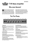
1
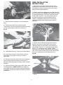
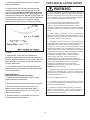
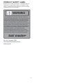
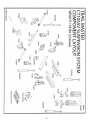
WARNING
equipped with larger than OE tires. Discuss this issue
with your tire and wheel dealer before installing larger tires
and do not use tire and/or wheel combinations that
compromise safe braking performance.
6. Supplied in this kit is a safety WARNING label. Install
this label inside the cab of the vehicle where it will be
highly visible to all operators of the vehicle.
2265 Crosswind Drive • Prescott, AZ 86301
(928) 636-3175 • www.p-a-g.net
CT10 N, S, SSV
1983-1994 GM S-10 / S-15
4WD Pickup and Blazer
4” Suspension Lift
CAUTION
INSTALLATION INSTRUCTIONS
1. Proper installation of Trail Master products requires
knowledge of recommended procedures for disassembly/
assembly of OE vehicles and components (i.e. steering tie
rods, control arms, brake calipers, etc.). Access to OE
shop manuals and special tools is required. Attempting to
install this kit without knowledge of these procedures may
affect the safety of your vehicle and/or the performance of
these components. Trail Master strongly recommends that
this kit be installed by a certified mechanic with off-road
experience.
WARNING
1. Read and understand all instructions, warnings and
cautions in these instructions, your owner’s manual and
related service manuals before the installation or use of this
product. DO NOT install or use this product if there is
anything you do not understand in these instructions or
related materials.
2. Use the appropriate tool for the job and be sure that
tools are in good condition. Failure to use proper tools and/
or tools in good condition may result in personal injury.
2. Certain Trail Master products are intended to improve
off-road performance. Modifying your vehicle for off-road
use may result in the vehicle handling differently than a
factory equipped vehicle. Use of oversize tires, suspension
lifts, body lifts and other suspension modifications may raise
your vehicle’s center of gravity resulting in an increased
tendency for the vehicle to pitch and roll during sudden
turns or abrupt maneuvers. Extreme care must be used to
prevent loss of control or vehicle roll over. Failure to drive
your modified vehicle safely may result in serious injury or
death. Drive at reduced speeds to ensure your ability to
maintain control of the vehicle under all driving conditions.
Always wear seat belts.
3. Always wear safety glasses while installing this kit to
avoid eye damage from debris, broken tools, etc.
4. Use Loctite 243 thread locker on all metal fasteners (per
the manufacturers directions) unless otherwise noted in
these instructions. Failure to use thread locker may result
in fasteners becoming loose over time.
5. The components included in this kit require regular
inspection for wear or damage. Periodically check fasteners
for proper torque (see chart of required torque
specifications on next page). Worn, damaged or loose
parts can fail suddenly resulting in loss of control of the
vehicle and personal injury.
3. DO NOT combine suspension lifts, body lifts or other lift
devices. Combined use of lifts may result in unsafe and/or
unexpected handling characteristics (see enclosed product
safety WARNING label).
PRE-INSTALLATION NOTES
4. Many states now have laws restricting vehicle
modifications such as lift, bumper height or other
alterations. Consult your state vehicle equipment laws to
determine if the installation of this kit or other modifications
are permitted.
1. Properly block and secure vehicle prior to installation.
5. The use of larger than OE tire and wheel
combinations may reduce the effectiveness of the braking
system (including ABS equipped) and increase the amount
of pedal pressure necessary to obtain a given braking
distance with normal stops and increase the stopping
distance in a panic stop. Drive at reduced speeds and
allow for extra stopping distance while driving a vehicle
Compare parts included in your system with the
enclosed parts list. Placing hardware with components
before you start may reduce installation time. Contact
your Trail Master dealer if any parts are missing or
appear to be different than those indicated on the parts
list.
WARNING
1
PRE-INSTALLATION NOTES
PARTS LIST
1. Not recommended for 1983 vehicles; if installed on 1983
vehicles, purchase of an additional 8025 sway bar kit and 8024
D-bolt kit required.
Bracketry
Upper Spring/U-Bolt Plate (CT10P) ....................................... 2
Spring Perch/Axle Brkt (CT10SP) .......................................... 2
Lower Control Arm Brkt Rear-Dvr (CT10CL) ......................... 1
Lower Control Arm Brkt Rear-Pass (CT10CR) ...................... 1
Lower Control Arm Brkt Front-Universal (CT10D) ................. 2
Upper Control Arm Brkt Front-Dvr (CT10LF) ......................... 1
Upper Control Arm Brkt Front-Pass (CT10RF) ...................... 1
Upper Control Arm Brkt Rear-Dvr (CT10LR) ......................... 1
Upper Control Arm Brkt Rear-Pass (CT10RR) ...................... 1
Front Diff. Brkt-Pass (950113) ................................................ 1
Front Diff. Brkt-Dvr Upper Straight (910904) .......................... 1
Front Diff. Brkt-Pass Upper Offset (910905) ........................... 1
Front Anti-Sway Bar Brkt ’84-’94 (CT10SBD) ........................ 2
Torsion Bar Crossmember Brkt-Dvr (CT10FD) ...................... 1
Torsion Bar Crossmember Brkt-Pass (CT10FP) .................... 1
Rear Crossmember Brkt (CT10R) .......................................... 1
Steering Center Link (CT10S1) .............................................. 1
Tie-rod Adjusting Sleeve (CT10TRX) .................................... 2
9/16-18 x 2-5/8" x 7-3/8" sq U-Bolt (0918258Q) ..................... 4
Shock Absorbers
Front 52620-W (N7), 62620-W (SS), 72620-W (SSV) ........... 2
Rear 55430-W (N7), 65430-W (SS), 75430-W (SSV) ............ 2
Hardware
7/8" O.D. x 2" Lg Sleeve (34) .................................................. 4
7/8" O.D. x 1-11/16" Lg Sleeve (66) ....................................... 4
7/8" O.D. x 1-1/4" Lg Sleeve (67) ............................................ 1
7/8" O.D. x 3/8" Lg Sleeve (60) .............................................. 1
1/2" Sq Washer (CT10LP) .................................................... 10
1/2" Channel Brkt (CT10BP) ................................................... 2
3" Relocation Brkt (B301WS) .................................................. 4
2" Shaped Brake Line Brkt (T86FBB) .................................... 1
9/16-18 Hex high Nut (N96FH) .............................................. 8
9/16-12 x 3-1/2" Hex Head bolt (96312CHHC) ..................... 4
9/16" SAE Flat Washer (W96S) ............................................. 8
9/16-12 Hex Lock Nut (N96SCL) ........................................... 4
1/2-13 x 4" Hex Head Bolt (12400CHHC) .............................. 4
1/2-13 x 3" Hex Head Bolt (12300CHHC) .............................. 1
1/2-13 x 1-1/2" Hex Head Bolt (12112CHHC) ..................... 10
1/2-13 x 1-1/4" Hex Head Bolt (12114CHHC) ....................... 4
1/2-13 Hex Locknut (N12CL) ................................................ 19
12mm-1.75 x 90mm Hex Head Bolt (12M090H175) ............. 1
7/16"-14 x 1-1/4" Hex Head Bolt (76114CHHC) .................... 9
1/2" x 12mm Flat Washer (W12F) ......................................... 42
7/16-14 Hex Locknut ............................................................... 9
3/8-16 x 1-1/4 Hex Head Bolt ................................................. 5
3/8-16 x 1-1/4 Self Tapping Hex Head Bolt (38114HWHT) .. 2
5/16" Flat Washer (W56F) ..................................................... 22
3/8-16 Hex Locknut (N38CL) .................................................. 9
9/16" Flat Washer (W96F) ....................................................... 8
3/8" Flat Washer (W38F) ....................................................... 20
5/16-18 x 1" Hex Head Bolt (56100CHHC) ........................... 2
5/16-18 Hex Locknut (N56CL) ................................................ 2
1/4" & 5/16" Flat Washer (W14F) ............................................ 8
1/4-20 Tennerman Nut (14100TENN) .................................... 4
1/4-20 Hex Locknut (N14CL) .................................................. 4
1/4-20 x 1" Carriage Head Bolt (14100CCGE) ...................... 4
3/4" O.D. x 1-1/4" Lg Sleeve (53) ........................................... 4
3/8-16 x 2-1/2" Lg hex Head Bolt (38212CHHC) .................. 4
3/32" x 1-1/4" Lg Cotter Key (332114) .................................... 2
1/8" x 1-1/4" Lg Cotter Key (180114) ..................................... 3
2. Special literature or tools required: OE service manual for
model/year of vehicle. Necessary tools: OTC#J25517C or
J 36202 torsion bar tool, ball joint and tie rod separators refer
to GM manual, plasma cutting machine or cutoff wheel, disc
grinder, die grinder with carbide burr or equivalent, and
inclinometer. Additional tools unique to installation are
mentioned in the following instructions.
3. System will not work on vehicles with ZR2 or highrider
package.
4. Removal of portions of OE bracketry are necessary to
accommodate this suspension system. Refer to FRONT
INSTALLATION steps 11-14 for details.
5. Modification of exhaust crossover necessary to
accommodate lowering of differential. Trail Master offers two
kits to perform this modification. Part #CX43 for the 4.3 liter
models up to 1992. Part #CX28 for the 2.8 liter models. Each kit
comes complete with instructions and hardware. An
experienced exhaust shop can perform this modification.
6. Ride Height: Due to payload options and initial ride height
variances of the S vehicle, the designation of “4” lift is a
“ground” figure. With OE torsion bar settings, your vehicle will
retain it’s stock attitude. Final ride height dimensions may vary
in accordance to the original vehicle attitude.
7. Adhere to recommendations when replacement fasteners,
retainers, and keepers are called out in OE manual. This
system may not include all replacement fasteners
recommended by the OE manual. Additional replacement
fasteners should be obtained prior to installation of the system.
8. Thoroughly clean underside of vehicle prior to component
installation. Concentrate on areas receiving bracketry.
9. If installation is to be performed without assistance of
vehicle hoist, Trail Master recommends performing rear
alterations first.
GLOSSARY OF TERMS
TM:
DRV:
PASS:
OE:
SRS:
Trail Master
Driver’s side of the vehicle
Passenger’s side of the vehicle
Original equipment
Supplemental Restraint System
TORQUE SPECIFICATIONS
1/4 FASTENERS .......................................................... 10'LBS.
5/16 FASTENERS ........................................................ 17'LBS.
3/8 FASTENERS .......................................................... 30'LBS.
7/16-14 FASTENERS .................................................. 50'LBS.
7/16-20 FASTENERS .................................................. 55'LBS.
1/2-13 FASTENERS ..................................................... 75'LBS.
1/2 U-BOLTS ...........................................................65-80'LBS.
9/16 FASTENERS ...................................................... 110'LBS.
9/16 GRADE 8 FASTENERS ..................................... 170'LBS.
9/16 U-BOLTS ......................................................... 75-90'LBS.
5/8 FASTENERS ........................................................ 150'LBS.
5/8 U-BOLTS .........................................................85-110'LBS.
3/4 FASTENERS ........................................................ 175'LBS.
2
FRONT INSTALLATION
INSTRUCTIONS
1. Block and secure vehicle. Disconnect battery. Remove
battery and box on late models to access vacuum shift
actuator. On early models, actuator is located rearward of
battery, not requiring removal of battery. Remove spring
clip and remove cable from actuator on both models.
2. Raise vehicle with hydraulic jack or equivalent and
place jack stands under frame away from lower control arm
anchors. Remove wheels, skid plates, and front sway bar.
3. Measure length of exposed thread on torsion bar
adjustment bolts. Record figures here, DVR __________,
PASS __________ for use when reassembling. Using
#J22517C or #J36202 torsion bar tool or equivalent, unload
torsion bars.
Fig. 9
10. Using hydraulic jacks or equivalent, support
differential. Disconnect the “lock” indicator wire plug from
differential. Remove fasteners mounting differential and
actuator cable to chassis. Carefully remove differential
assembly from chassis.
4. Tag torsion bars DVR front and PASS front,
respectively. Remove rear torsion bar crossmember and
torsion bars.
11. Important installation Note: Trail Master
recommends all modifications to OE bracketry be
performed with plasma cutting devices, Sawz-All, or cut off
wheel. The use of a cutting torch is not recommended!
Check position of fuel, brake, and other lines in area prior
to cutting. Insulate or move to alleviate damage. For
safety, never work alone. Have fire extinguisher readily
available.
Note: On some models loosening or removal of exhaust
system may be required to remove torsion bar
crossmember.
5. Using hydraulic jack or equivalent, support lower control
arm. Dislodge and unplug ABS wire at frame, when so
equipped. Remove fasteners attaching brake line and ABS
wire to frame and upper control arm. Remove brake caliper
from knuckle and safely support. Do not allow caliper to
hang by hose!
12. CAUTION: Fuel lines are located inside frame on
driver side, exercise caution in this area. Scribe areas to
be cut on OE bracket prior to actual cutting. To remove
bottom section of OE rear upper control arm bracket:
(I)
Cut the extension stop gusset off flush with
frame.
(II)
Cut front surface of bracket 1/2" below the
bottom of frame, horizontally out 2". Cut
vertically down bracket to intersect horizontal
cut. Fig. 12A.
(III) Cut rear side of bracket flush with frame 3/4" up.
Cut bracket horizontally out 2" from this point.
Cut bracket vertically to intersect horizontal cut
and outside edge of receiver, Fig. 12B. You
should now have removed the OE extended
stop.
(IV) Trim front leg of lower receiver flush with outside
of frame. “Tune” leg rearward, Fig. 12C. Dress
and final fit STEP (31) to accommodate
installation of brackets “LR” and “RR”
respectively. Repeat step 12 on opposite side.
(V) Cut OE steering stabilizer chassis mount flush
withframe, Fig. 12D.
6. Remove fasteners retaining DVR inner C. V. joint to
differential flange. Disengage flange from differential.
Remove shock. Disengage outer tie rod from knuckle.
Disengage upper ball joint from knuckle. Remove D-bolts
from upper control arm. Remove upper arm from chassis.
7. Remove bolts attaching lower control arm to frame.
Remove arm/knuckle assembly from chassis. Repeat
steps 5 through 7 on opposite side.
8. Disengage inner tie rods from OE relay rod. Remove tie
rod sleeves from tie rod ends. Note tie rod ends are right
and left hand threaded. Tag for location, i.e. inner/outer
DVR or PASS. Disengage OE relay rod from pitman and
idler arm. Remove front compression stops located below
rear upper control arm receivers. Note position for
installation on TM brackets.
9. Early model “S” vehicles have a crossmember located
directly rear of engine, Fig. 9. This crossmember must be
removed. Remove brake line fasteners attached to
crossmember. Remove crossmember fasteners and
crossmember. Remove front drive shaft. Do not allow
slider yoke to disengage from shaft.
3
13. Scribe areas to be cut on OE bracket prior to actual
cutting. Cut DVR lower rear control arm receiver, front and
rear surfaces, vertically 3/8" toward inside of vehicle from
control arm hole. Join front and rear cuts with horizontal
cut, Fig. 14. You should now have removed rear OE
differential mount. Dress to accommodate bracket “CL”.
Fig. 12A
Fig. 14
14. Install DVR side front differential mount using straight
bracket “910904” as the outer extension. Use offset
bracket “910905” as the inner mount extension. Insert 1/2"
x 3" bolt, 1-1/4" sleeve, washers and nut provided into
upper frame pocket, Fig. 15. Do not tighten fasteners at
this time.
Fig. 12B
Fig. 15
15. Install bracket “950113” to PASS side differential
chassis mount. Utilize two 1/2" x 1 1/2" bolts, washers and
nuts provided. Loosely remount differential to drop brackets
using OE fasteners , Fig.16. Do not tighten fasteners at
this time.
Fig. 12C
16. Install bracket “CR” into PASS side lower rear control
arm receiver. Use 1-15/16 spacer, 9/16" x 3-1/2" bolt,
washers, and nut provided, Fig. 17. Note: “CR” must
move freely. Do not tighten fasteners at this time.
Fig. 12D
4
Fig. 16
Fig. 19A
Note: If you perform step 9, drill two 17/64" holes 5" in
from ends of crossmember “R”. Fig 19B. Install “R” with
17/64" holes up. After final adjustment of assembly “R”,
step 28, form brake lines over pinion, reattach brake line
using drilled holes and OE bolts.
Fig. 17
17. Install bracket “CL” into DVR side lower rear control
arm receiver. Use 1-15/16" spacer, 9/16" x 3-1/2" bolt,
washers, and nut provided. Bracket “CL” will also engage
rear differential mount, Fig. 18. Note: “CL” must move
freely. Do not tighten fasteners at this time.
Fig. 19B
19. Check clearance between differential and OE DVR
side lower control arm receiver. Minimum clearance 3/16".
If clearance is less than 3/16" relieve and dress receiver
and/or differential “fins” to gain clearance. Fig. 20.
Fig. 18
18. Join crossmember “R”, open side rearward, to brackets
“CR” and “CL”. Install and tighten 7/16" x 1-1/4" bolts,
washers, and nuts provided. Insert 12mm x 90mm bolt and
washer supplied, through “CL” into differential ear and
crossmember, retain with OE nut. Run up 7/16" and 12mm
bolts. Do not tighten at this time. Fig. 19A. Note slots in
“CR” and “CL” at engagement points. Raise differential
assembly (assembly “R”) for late models. Lower assembly
“R” for early models. Maintain identical engagement heights
on “CR” and “CL” with assembly “R”.
Fig. 20
5
20. Using an inclinometer, check pinion to transfer case
angles. Maximum variance 1 1/2 degrees. Adjust angle by
raising or lowering crossmember “R” and differential
assembly. Fig. 21. Maintain identical engagement heights
on “CR” and “CL” with assembly “R”.
23. If relay rod to differential clearance is adequate,
proceed to step 25. If not, you must lower assembly “R” to
gain clearance between relay rod and differential.
Warning: Do not sacrifice steering clearance for pinion
angle! Ensure engagement heights of “R” on “CR” and
“CL” are equal.
24. Torque 7/16" and 12mm fasteners in assembly “R” to
specification.
25. Torque 1/2" x 1-1/2" bolts retaining “940201” to PASS
chassis mount. Torque OE fasteners retaining differential
to “940201”. Note: crowding differential while tightening
fasteners may increase clearance between receiver “CL”
and differential. Refer to step 20.
26. Torque to specification, 1/2" x 3" bolt retaining DVR
side front differential mount. Torque OE fasteners mounting
differential to drop brackets.
Fig. 21
27. Make steering sweep. Again check clearance between
relay rod and differential ear. Refer to Fig. 23 Warning:
Minimum acceptable clearance 7/16". In the event that
clearance dimension is less than 7/16", you must revert to
steps 23-27. If clearance measurement is sufficient, torque
9/16" cross bolts in brackets “CR” and “CL”. Continue to
step 29.
21. Install inner tie rod ends into replacement relay rod “S”.
Torque to OE specification. Install relay rod assembly.
Torque idler and pitman arm nuts to OE specifications.
Install cotter pins provided. Fig. 22.
28. Check clearance between differential output flange and
OE lower rear control arm receiver, PASS and DVR side.
Minimum clearance 3/8". Dress receiver ear or tune to gain
clearance. Fig. 29A. Make diagonal measurement on rear
of system as shown. Fig. 29B. In the event that system
fails to meet dimensional specification, locate interference
and alleviate. Failure to meet this specification may result
in the inability of the completed system to meet vehicle
alignment specification. Check clearance between front
differential and engine oil pan. It may be necessary to
concave pan at PASS side axle tube flange to gain
adequate clearance. A minimum clearance of 1/2 inch
between differential flange and engine oil pan is required.
Fig. 22
22. Make steering sweep checking clearance between
relay rod and differential ear on DVR side. Fig. 23.
Warning: Minimum acceptable clearance 7/16".
Fig. 29A
Fig. 23
6
Fig. 29B
Fig. 31
29. Note position of ears on upper portion of bracket “CL”.
Measure and locate center of ears, transfer coordinates to
external surface of OE receiver. Drill 1/2" hole through OE
receiver and bracket “CL”, in front and rear legs. Install
7/16" sleeve in gap between bracket “CL” and front leg of
OE receiver. Install 1/2" x 1 1/2" bolt assemblies running
front bolt through 7/16" sleeve. Torque fasteners to
specification. Fig. 30.
Fig. 32
Fig. 30
30. Install bracket “LR” in DVR side upper rear OE control
arm receiver. Use 1/2" x 4" bolt, washers, nuts, tabs “LP”,
and 1-11/16" sleeve provided. Note: “LP” fits one way into
OE D-bolt adjustment tab. Reaming center of OE “D” slots
will ease installation of cross bolt. Do not tighten
fasteners at this time. Fig. 31. Repeat on PASS side
using bracket “RR”.
Fig. 33
33. Install bracket “LF” in DVR side upper front control arm
receiver. Utilize 1/2" x 4" bolt, washers, locator tabs, 1-11/
16" sleeve and nut provided. Install 1/2" x 1-1/4" bolt,
washers, and nut through hole in top of OE bracket and
bracket “LF”. Do not tighten fasteners at this time.
Fig. 34. Note: Reaming of OE holes may be necessary to
obtain a good fit between OE receiver and TM brackets.
Using bracket “RF” repeat step on PASS side.
31. Align holes in bottom of “LR” with holes in “CL”. Insert
two 7/16" x 1-1/4" bolts and washers through “LR”. Install
washers and nuts provided on inside of “CL”. Note: it may
be necessary to ream top 7/16" hole to install bolt. Torque
7/16" bolts first; then 1/2" cross bolt. Fig. 32. Repeat step
on PASS side engaging bracket “RR” and “CR”.
32. On early models with closed top upper rear receivers,
using hole in top of brackets “LR” and “RR” respectively to
index, drill 1/2" hole in top of OE bracket. Install 1/2" x 1-1/
2" bolt, washer and nut provided. Shim gap between “LR”
and OE receiver with one “LP” tab. Tighten fasteners to
specification. Fig. 33.
7
Fig. 34
Fig. 36A
34. Insert upper control arm into brackets “LF” and “LR”.
Run up 1/2" x 1-1/4" bolt in top of bracket “LF” and
receiver. Using hole in bracket “LF” as template, drill 1/2"
hole through frame. Insert 1/2" x 1-1/4" bolt and washer
through “LF”. Place bracket “BP” over bolt inside frame.
Install nut into channel side of “BP” and tighten to
specification. Tighten cross and top bolt to specification.
Fig. 35. Remove control arm. Note: it may be necessary
to “tune” OE front bracket to facilitate installation of control
arm. Repeat procedure on PASS side using corresponding
control arm.
Fig. 36B
36. Install OE compression stops on bottom of brackets
“LR” and “RR”. Torque to specification. Fig. 37.
37. Using hydraulic jack or equivalent, raise lower control
arm assembly into TM brackets. Install and run-up OE
control arm bolts. Engage inner C.V. to differential mating
flange. Install OE fasteners, torque to specification. Install
brake caliper and caliper bolts, torque to specification.
Fig. 35
35. Install brackets “D” into front OE control arm receivers.
Utilize 9/16" x 3-1/2" bolts, washers, 1-15/16" sleeves and
nuts. Brackets should fit flush with bottom of frame. Note:
It may be necessary to dress frame to obtain flush fit.
Fig. 36A. Using bracket “D” as template, drill two 1/2"
holes in flat of frame for each bracket as indicated,
Fig. 36B. Install 1/2" x 1-1/2" bolts, washers, and nuts.
Torque 1/2" fasteners first followed by 9/16" cross bolts to
specification.
Fig. 37
8
38. Insert the 1/4" x 1" carriage bolts into square hole of 1"
x 3" flat brackets “WS”. Tighten tennerman nut to hold bolt
in place. Attach upper end of bracket to frame at original
brake line mount point using OE fastener. Remove bolts
and clamps retaining brake lines to frame at shock towers.
Carefully acquire slack in brake lines. Carefully extend
brake line outward and down and mount to 1/4" bolt in
extension bracket. DO NOT KINK LINE. Remount lines to
frame using OE clamps and bolts. Fig. 39.
41. Insert upper control arm into TM brackets. Check for
interference at rear engagement. If necessary, remove
upper control arms and relieve inside edge and dress rear
bottom of upper A-arms on both PASS and DVR side arms
to eliminate interference. Fig 42.
Fig. 42
42. Reinstall upper A-arms into TM brackets using OE “D”
bolts. Engage ball joint, do not tighten at this time.
Check clearance between A-arm and shock with “D” bolts
adjusted inward as far as possible. Minimum clearance to
shock 1/8". Using template supplied, relieve and dress
control arm to gain clearance. All corners should be
radiused and smooth. Do not use torch. Fig 43.
Fig. 39
39. Vehicles with ABS brakes will require loosening
clamps retaining ABS wires to frame. Acquire sufficient
slack in frame lead to reconnect knuckle sensor lead.
Remove excess slack in ABS leads using OE clamps and
tie-wraps provided. Ensure relocation is clean and secure.
See also step 45.
40. Install shocks supplied. Use OE bolts, washers, and
nut. Shim shock forward, if necessary, remove upper
control arms and using 1/2" washers provided to gain
clearance between shock body and C.V. Fig. 41. Torque
OE fasteners to specification.
Fig. 43
43. Reinstall control arm with OE “D” bolts facing inside
out, shock removal will be necessary. Refer to step 5
location / direction of “D” bolts. Centrally locate “D” bolt in
adjustment slot with major portion down. Run up “D” bolts,
do not tighten. Engage ball joint to knuckle and torque to
specification. Reinstall shock.
44. Reinstall brake hose/ABS lead to control arm using
OE fasteners. Turn knuckle assembly “lock” to “lock” and
note movement and position of brake hose and ABS lead.
Ensure ABS lead/hose routing is clean and secure. Torque
to specification. See also step 40. Repeat steps 38-45 on
opposite side.
Fig. 41
9
45. Install tie-rod sleeves “TRX”. Thread engagement of
inner and outer tie-rod ends to “TRX” must be identical.
Initial “TRX” adjustment, 24-7/16" center/center from inner
to outer tie rod ends. Engage outer tie-rod ends to
knuckles, torque to specification. Install cotter keys.
Safety Note: inner DVR side “TRX” clamp/bolt must be
rotated to bottom. Fig. 46. This procedure will ensure
clearance between clamp and differential.
Fig. 48
48. Install OE torsion bar crossmember onto “FD” and “FP”
using OE fasteners. Torque TM and OE fasteners to
specification.
49. Install torsion bars. Reload bars using the #J36202
torsion bar tool. Set adjustment bolts to initial setting
obtained from step 3. Note: Minor torsion bar adjustment
may be required to level vehicle side to side. Set trim
height within OE specifications.
Fig. 46
46. Install sway bar extension brackets “SBD” to frame
utilizing 3/8" x 1-1/4" bolts, washers, and nuts. Do not
tighten. Install sway bar/anchors to A-arms. Install bar to
“SBD”. Fig. 47. Tighten all fasteners to specification.
50. Vacuum actuator relocation: on early models, move
actuator from side of fender to inner fender. Using OE
bracket as a template, drill two 5/16" holes into inner
fender. Install 5/16" x 1" bolts, washers, and nuts supplied.
Tighten to specification. Fig. 51A. Relocate cable over
heater hoses. Reinstall cable and clip. Ensure relocation of
actuator provides adequate slack in cable.
NOTE: Lifting A-arms will ease installation of sway bar.
On late models with vacuum actuator located under
battery, relocate assembly over 1 OE hole toward inside of
vehicle and reattach using OE fastener. Using bracket as a
template, drill a 5/16" hole in inner fender and install
second OE fastener. Torque both to specification. Plug OE
mount hole with 5/16" bolt, washer, and nut. Reinstall
actuator cable and clip. Ensure relocation of actuator
provides adequate slack in cable. Reinstall battery and
box. Fig. 51B.
Fig. 47
47. NOTE: Fuel lines run inside frame on DVR side. Use
caution when performing this step. Dress welds on bottom
of frame. Ream OE torsion mount frame holes to 7/16".
Install bracket “FD” on DVR side of vehicle using 7/16" x
1-1/4" bolts, washers, and nuts provided. Fig 48. Use 1/2"
washers to shim space between frame and “FD” if so
required. Using front hole in “FD” as guide, drill 5/16" in
frame. Install 3/8" x 1" self tapping bolt provided. Repeat
using “FP” on PASS side.
Fig. 51A
10
REAR INSTALLATION
INSTRUCTIONS
1. Block and secure vehicle. Remove shocks. Using
hydraulic jack or equivalent, raise rear of vehicle. Place
jack stands under frame on each side in front of spring
hangers. Remove wheels and tires.
2. Remove retainer nut holding brake line to frame bracket.
Slit OE bracket with saw. DO NOT cause abrasion to brake
line. Bend bracket open, remove line. Close bend. Install
bracket “BB” using 3/8" x 1-1/4" bolt, washers, and nut
provided. Reinstall line into “BB” and tighten OE line
retainer nut. Fig. 2R. On 1994 vehicles, remove bolts
retaining emergency brake cable to frame at the front
spring eye.
Fig. 51B
51. Perform exhaust modification. See Pre-Installation
notes.
52. Reinstall drive shaft. Check clearance at OE
crossmember. Remove crossmember and press front edge
or peen to gain clearance. Minimum clearance 1/2".
Fig. 53.
Fig. 2R
3. Support rear axle. Remove spring u-bolts. Remove
springs. Lower axle. On 1994 models, remove bolts
retaining emergency brake cables to frame above front
spring hanger. Insert 1/4" x 1" carriage bolts into square
hole of 1" x 3" flat brackets “WS” supplied. Tighten
tennerman nut to hold bolt in place. Mount “WS” brackets
(with 1/4" bolt down) to frame using OE bolts. Mount brake
lines to 1/4" stud and secure with washers and nut.
Fig. 3R.
Fig. 53
53. Install wheels and tires. Torque nuts to specifications.
54. Lower vehicle to ground. Torque lower control arm
anchor bolts. Torque upper control arm “D” bolts to
specification.
55. Retorque all fasteners. Check brake lines for damage.
Check steering clearances. Check to ensure there is
adequate clearance between all rotating, mobile, and fixed
members.
56. Align front end. Set torsion bars to OE Z height. Align
to OE specifications. SAFETY NOTE: after setting toe,
ensure DVR side inner tie rod sleeve clamp/bolt assembly
is on bottom. This procedure will ensure steering clearance
at differential.
Fig. 3R
11
4. Clamp spring pack. Remove center pin, invert pin,
torque to specification.
POST-INSTALLATION NOTES
WARNING
5. Install brackets “SP” onto axle, short end forward.
Install springs over axle, attach spring ends using OE
bolts. Run up, do not tighten anchor bolts at this time.
Install u-bolts placing TM bracket “P” atop spring and OE
u-bolt plate on bottom of axle. Fig. 5R. Use 9/16" high nuts
and OE washers to retain. Run up. Crowd OE u-bolt plates
rearward to ensure clearance for installation of larger
bodied shocks provided. Torque u-bolts to specification.
1. Check all fasteners for proper torque before driving the
vehicle for the first time with this kit, after the first 500 miles,
after each off-road use and during routine vehicle servicing.
Worn, damaged or loose parts can fail suddenly resulting in
loss of control of the vehicle and personal injury.
2. In ALL steering and suspension positions, check to
ensure that there is adequate clearance between ALL
rotating, moving, fixed and heated members. Ensure
adequate clearance around steering components, exhaust
components, brake lines, fuel lines, fuel tank and electrical
wiring.
3. Visually inspect components for wear or damage after
each off-road use and during routine vehicle servicing. Worn,
damaged or loose parts can fail suddenly resulting in loss of
control of the vehicle and personal injury.
4. Trail Master does not recommend a particular tire and
wheel combination for use with its products and assumes no
responsibility for customer choice of tires and wheels.
Consult your owner’s manual for recommended tire sizes
and warnings related to use of oversize tires and wheels. In
general, larger tire and wheel combinations may increase
stress and wear on steering components leading to increased
maintenance and greater risk of component failure,
including loss of steering control. Property damage or
personal injury may result. Large tire and wheel
combinations may also alter speedometer calibration,
reduce braking effectiveness and alter vehicle center of gravity
height (See product safety warnings). Check with an
experienced off-road shop for the tire and wheel
combinations that work best on your truck. Remember,
BIGGER isn’t necessarily better.
Fig. 5R
6. Install shocks. Torque OE mount fasteners to
specification. Check clearance between shock body and
axle tube. Minimum clearance 1/4". Slot holes in OE u-bolt
plate if clearance is insufficient. Install wheels and tires.
Torque to specification.
7. Lower vehicle to ground. Torque spring hanger and
shackle fasteners to specification. Recheck all fasteners
for their correct torque.
5. Trail Master’s goal is to provide you with the best system
possible for a reasonable cost. It must be noted that the
components in your Trail Master system do not eliminate OE
component weaknesses.
Extended Cab Only:
Carrier bearing crossmember relocation.
1. Support rear drive shaft assembly. Remove bolts
mounting bearing to crossmember.
6. Perform headlight adjustment.
2. Remove fasteners mounting crossmember to chassis.
7. Set vehicle alignment within OE specifications. The size
of rim and tire combinations should be considered when
making front end adjustments.
3. Relocate crossmember under frame using 1-1/4"
spacers between frame and crossmember. Retain
crossmember to frame using 3/8" x 2-1/2" long bolts,
washers, and lock nuts.
8. Retain this and all information regarding your altered
vehicle for future reference. Thank you for choosing Trail
Master. For questions, contact our Technical Assistance
Department at (928) 636-3175.
4. Remount bearing to crossmember using OE bolts.
Torque all fasteners to specification.
12
PRODUCT SAFETY LABEL
Supplied in kit is a safety warning label. Install label inside cab.
Locate label in a highly visible location to all operators of this
vehicle. If label becomes lost or damaged, contact Trail Master
at (928) 636-3175 for a replacement.
WARNING
The suspension of this vehicle has been modified to
improve off-road performance. As a result, this vehicle
may handle differently than factory equipped vehicles.
Extreme care must be used to prevent loss of control
or roll over during sharp turns or abrupt maneuvers.
Failure to drive this vehicle safely may result in serious
injury or death. Do not drive this vehicle unless you
are familiar with its unique handling characteristics and
are confident of your ability to maintain control under
all driving conditions. Consult the instructions
accompanying this product and the vehicle owner’s
manual for additional product safety warnings. Always
wear seat belts, reduce your speed and drive safely.
trail master
®
Rev. 03, Copyright 07/06
Performance Automotive Group
www.p-a-g.net
13
14
15
2265 Crosswind Drive • Prescott, AZ 86301
(928) 636-3175 • www.p-a-g.net
© Performance Automotive Group, Rev. 7/97, 10/99, 7/02, 5/03, 2/06, 07/06
16
Printed in U.S.A.
Form No. ICT10