1
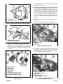
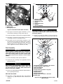
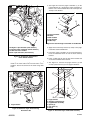
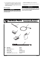
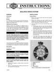
INSTRUCTIONS
®
REV. 05-20-2005
-J02620
Kit Number 91665-03
SECURITY PAGER KIT, SHORT HARNESS
General
This kit is designed for installation on all 1996 and later
Dyna Glide, 2000 and later Softail, 1997 and later FL
Touring, and 2004 and later Sportster® models equipped
with a security system.
NOTE
A Service Manual for your model motorcycle is available
from any Harley-Davidson Dealer.
1WARNING
The rider's safety depends upon the correct installation
of this kit. Use the appropriate service manual procedures. If the procedure is not within your capabilities or
you do not have the correct tools, have a HarleyDavidson dealer perform the installation. Improper
installation of this kit could result in death or serious
injury. (00333a)
The Harley-Davidson Security System Pager is designed to
operate with the original Smart Siren or as a silent paging
system only.
This instruction sheet covers the installation of the kit on
Dyna Glide, Softail, FL Touring, and Sportster model
motorcycles. Use the appropriate procedure for your
motorcycle.
FCC Notice
This equipment has been tested and found to comply with
part 95 of the FCC rules. Any adjustment that could result in
a violation of these rules is recommended to be performed
by or under the immediate supervision and responsibility of
a person certified as technically qualified to perform
transmitter maintenance and repair duties in the private land
mobile services.
The replacement of any transmitter components (crystal,
semiconductor, etc.) that could result in a violation of the
rules is prohibited.
Signal Range
NOTE
Environmental and geographic conditions may affect signal
range.
The average reception range is approximately 400 yards.
The actual reception range could be higher or lower
depending on the location and/or the presence of obstacles
between the vehicle and the receiver. The reception range
can also be affected by the presence of strong
electromagnetic interference from outside sources.
The system is equipped with a range confirmation feature
notifying the owner when the receiver is no longer in the
reception range.
Installation – Dyna Glide 1996 and Later
1. Refer to the Owner’s Manual and follow the instructions
given to disarm the security system, if so equipped.
2. See the Service Manual for instructions given to remove the
seat.
1WARNING
To prevent accidental vehicle start-up, which could
cause death or serious injury, disconnect battery cables
(negative (-) cable first) before proceeding. (00307a)
1WARNING
Disconnect negative (-) battery cable first. If positive (+)
cable should contact ground with negative (-) cable connected, the resulting sparks can cause a battery explosion,
which could result in death or serious injury. (00049a)
3. 2003 and Earlier Models: Refer to the Service Manual
and follow the instructions given to disconnect the battery cables, negative cable first.
4. See Figure 1. Position Siren bracket.
NOTE
If the pager is being used as a silent paging system only (no
siren installed), it will be necessary to purchase separately a
siren bracket (part number 70470-01A) and four self-tapping
screws (part number 2501A) in order to mount the pager
transmitter. For 1996-1999 Dyna Glide Models Only, See
Figure 1. Carefully center the siren bracket on the frame pan
as shown. Use the siren bracket as a template to transfer
the location of the four mounting holes to the frame pan.
Remove the siren bracket and drill (4) 9/64” (.141mm) holes
at the locations transferred from the siren bracket. For 2000
- 2003 Dyna Glide Models Only: The required holes in the
frame pan are already provided. Proceed to Step 8.
5. See Figure 1. Remove and retain four self-tapping
screws, and flip the bracket over.
6. See Figure 2. Disconnect the siren harness connector
from the siren.
NOTE
Hold the pager transmitter against the siren assembly, and
test fit the assembly in the opening in the frame pan to
determine the correct location of the pager, before applying
the hook and loop fasteners.
1 of 10
i04010
1
9. If the pager is being used as a silent paging system
only (no siren installed): See figure 2. Locate the
security connector - main harness (siren harness connector). Remove the dust cap from the harness (2) and
(See Figure 3.) connect to the Pager harness large connector. Connect the dust cap to the Pager harness connector - long harness lead (7). Bundle the pager harness using a cable strap and secure the harness to the
frame in an area away from moving parts. Proceed to
Step 12.
2
1.
2.
8. Connect the connector (6) from the short harness lead
to the pager transmitter.
10. Connect the connector (7) from the long harness lead to
the siren.
Siren bracket
Self-tapping screws
11. Bundle the excess harness using a cable strap (5).
Figure 1. Removal of Siren Bracket (2003 and earlier)
i04937
i04009
1
1
2
3
2
3
1.
2.
Siren and bracket assembly
Siren harness connector
Figure 2. Disconnect Siren Harness Connector
7. See Figure 3. Clean the mounting surfaces of the pager
transmitter (1) and siren bracket (2) using alcohol or
other suitable cleaner, and apply the hook (3) and loop
(4) fasteners.
i04936
6
8
2
1. Pager antenna loop
2. Connector
3. Cable straps
Figure 4. Install Pager Antenna
12. See Figure 4. Install the pager antenna by positioning
the loop (1) around the opening in the frame pan with
the connector (2) located at the rear. Secure the antenna to the frame pan using cable straps (3).
4
3
i04938
1
Pager transmitter
Siren bracket
Hook fastener
Loop fastener
Cable strap
Connector (short harness lead)
Connector (long harness lead)
Pager harness large connector
Figure 3. Install Pager Transmitter to Siren Bracket
(2003 and earlier)
-J02620
3
4
5
5
7
1.
2.
3.
4.
5.
6.
7.
8.
1
2
1.
2.
3.
4.
5.
Pager transmitter
Siren bracket assembly
Cable strap
Antenna connector
Short lead harness connector
Figure 5. Connect the Antenna to the Pager
Transmitter (2003 and earlier)
2 of 10
i02506a
i04939
5
1
5
6
3
6
2
7
3
4
1
3
2
1. Siren bracket assembly
2. Antenna loop
3. Self-tapping screws
Figure 6. Install Siren Bracket (2003 and earlier)
13. See Figure 5. Secure the pager transmitter (1) to the
siren bracket assembly (2) using a cable strap (3).
14. Connect the antenna connector (4) to the pager transmitter.
15. See Figure 2. Connect the siren harness connector (2)
to the large connector on the pager harness.
1.
2.
3.
4.
5.
6.
7.
Electrical caddy cover
Electrical caddy
Socket head screw
Washer
Button head screws
Washers
Siren (If equipped)
Figure 7. Electrical Caddy Removal
1WARNING
To prevent accidental vehicle start-up, which could
cause death or serious injury, remove maxi-fuse before
proceeding. (00251a)
21. Remove the electrical caddy (2) from the frame by
removing and saving the front screw (3) and washer (4)
i02506b
16. See Figure 6. Fit the siren bracket assembly (1) over
the four holes in the frame pan. Make sure the antenna
loop (2) is not pinched under the bracket. Secure the
bracket using the four self-tapping screws (3) saved
earlier. Tighten the screws to 5-8 ft-lbs (8-11 Nm).
2
9
8
6
7
1
6
10
Final Assembly
7
1WARNING
Connect positive (+) battery cable first. If positive (+)
cable should contact ground with negative (-) cable connected, the resulting sparks can cause a battery explosion, which could result in death or serious injury.
(00068a)
10
5
3
17. Connect the battery cables, positive cable first.
4
18. Install the seat according to the applicable Service
Manual instructions.
1WARNING
After installing seat, pull upward on front of seat to be
sure it is in locked position. While riding, a loose seat
can shift causing loss of control, which could result in
death or serious injury. (00070a)
19. Refer to the Pager Operations Manual supplied with this
kit for operating instructions.
2004 and later models
20. See Figure 7. Firmly grasp both sides of the electrical
caddy cover (1) pull outward to remove. Remove the
maxi-fuse.
-J02620
1.
2.
3.
4.
5.
6.
7.
8.
9.
10.
Accessory security connector - main harness
Larger connector - Pager harness
Siren (If Equipped)
Electrical caddy
Pager harness connector - long lead
Pager transmitter
Antenna wire
Antenna connector
Pager harness connector - short lead
Cable straps
Figure 8. Pager installation to electrical caddy
(2004 and later)
3 of 10
and the two button head screws (5) and washers (6) for
later installation. Pull the electrical caddy outward and
down exposing inward side.
22. See Figure 8. Obtain items from kit. Locate and remove
the accessory security connector (1) attached to the
main harness and pull it up and under the seat area.
Plug the large connector (2) of the pager harness into
the accessory security connector (1).
i04942
2
3
1
4
NOTE
Remove dust cap from accessory security connector (1) if
not connected to the siren.
23. Slide the siren (3) (if equipped) into the slot on the inward
side of the electrical caddy (4) with the siren connection
facing the vehicle. Take the longer lead harness connector (5) and route it down along the frame and plug it into
the siren (3).
24. Set the pager transmitter (6) in the area located under
the seat. Connect the short harness lead (9) to the
transmitter..
25. See Figure 4. Install the pager antenna by positioning
the loop (1) around the opening in the frame pan with
the connector (2) located at the rear. Secure the antenna to the frame pan using cable straps (3).
26. Bundle the pager harness using a cable strap if the
pager is being used as a silent paging system only (no
siren installed). Connect the dust cap to the harness
connector long lead and bundle the pager harness to
the cable strap.
1. Siren harness connector
2. Pager harness
3. Pager harness – short lead
4. Cable strap
Figure 9. Connect Pager Harness to Siren
1WARNING
To prevent accidental vehicle start-up, which could
cause death or serious injury, disconnect battery cables
(negative (-) cable first) before proceeding. (00307a)
1WARNING
Disconnect negative (-) battery cable first. If positive (+)
cable should contact ground with negative (-) cable connected, the resulting sparks can cause a battery explosion,
which could result in death or serious injury. (00049a)
3. Disconnect battery cables, negative cable first.
27. Secure pager to electrical caddy (4) using a cable strap
(10).
4. Remove the debris shield according to the applicable
Service Manual instructions.
28. Make sure antenna loop is not pinched and secure harness to the frame in an area away from moving parts.
5. See Figure 9. Disconnect the existing siren harness
connector (1) from the siren (if equipped).
29. Replace electrical caddy using hardware removed earlier.
Attach the caddy cover.
NOTE
It may be necessary to loosen the rear fender back to gain
clearance for the pager harness connector.
30. Replace the maxi-fuse.
31. Install the seat according to the applicable Service
Manual instructions.
6. Working from below, route the long end of the pager
harness with the single connector (2) up through the
gap between the rear fender and battery tray.
1WARNING
After installing seat, pull upward on front of seat to be
sure it is in locked position. While riding, a loose seat
can shift causing loss of control, which could result in
death or serious injury. (00070a)
7. If the pager is being used as a silent paging system
only (no siren installed): Bundle the pager harness
using a cable strap, and secure the harness to the
frame in an area away from moving parts. Proceed to
Step 10.
32. Refer to the Pager Operations Manual supplied with this
kit for operating instructions.
Installation – Softail
NOTE
The following procedure shows the installation on 2003 and
later models. Installation on 2000 through 2002 models may
vary slightly.
1. See the Owner’s Manual to disarm the security system.
2. Refer to the applicable Service Manual instructions
given to remove the seat.
-J02620
8. Connect the short pager harness lead (3) to the siren.
9. Connect the siren harness connector (1) to the large
connector on the pager harness.
10. Pull up slack in wires, and secure pager and siren harnesses to main harness using cable straps (4) as needed.
NOTE
Install the hook fastener on the pager transmitter on the same
side as the harness connector (as shown in Figure 10).
11. See Figure 10. Clean the mounting surfaces of the
pager transmitter (1) and battery (2) using alcohol or
other suitable cleaner, and apply the hook (5) and loop
(4) fasteners.
4 of 10
i04943
1WARNING
After installing seat, pull upward on front of seat to be
sure it is in locked position. While riding, a loose seat
can shift causing loss of control, which could result in
death or serious injury. (00070a)
1
6
5
18. Install the debris shield according to the applicable
Service Manual instructions.
19. Refer to the Pager Operations Manual supplied with this
kit for operating instructions.
3
Installation – FL Touring Models
4
2
NOTE
The following procedure shows the installation on 2002 and
later models. Installation on 2001 and earlier models may
vary as noted.
1. See the Owner’s Manual to disarm the security system.
1. Pager transmitter
2. Battery
3. Pager harness
Connector
4. Loop fastener
5. Hook fastener
6. Pager antenna
2. Remove the seat according to the applicable Service
Manual instructions.
3. 2004 and Later Models: Remove the MAXI-Fuse.
Figure 10. Install Pager Transmitter
12. Connect the pager harness connector (3) to the pager
transmitter.
13. Connect the pager antenna (6) to the pager transmitter.
1WARNING
Connect positive (+) battery cable first. If positive (+) cable
should contact ground with negative (-) cable connected,
the resulting sparks can cause a battery explosion, which
could result in death or serious injury. (00068a)
14. Install battery cables, positive cable first.
1WARNING
To prevent accidental vehicle start-up, which could
cause death or serious injury, disconnect battery cables
(negative (-) cable first) before proceeding. (00307a)
1WARNING
Disconnect negative (-) battery cable first. If positive (+)
cable should contact ground with negative (-) cable connected, the resulting sparks can cause a battery explosion, which could result in death or serious injury.
(00049a)
15. Install the pager transmitter (1) onto the battery (2).
4. 2003 and Earlier Models: Refer to the Service Manual
and follow the instructions given to disconnect the battery cables, negative cable first.
16. See Figure 11. Route the pager antenna around the battery as shown. Secure the antenna to the frame tubes
using cable straps.
5. Remove the right saddle bag according to the applicable Service Manual instructions.
17. Refer to the Service Manual, and follow instructions to
install the seat.
i04944
6. Remove right side cover according to the applicable
Service Manual instructions.
7. See Figure 12. 2002 and later Models Only: Remove
and retain two nuts, and carefully pull the electrical
caddy away from the mounting studs.
1
2
i04945
1
2
2
1.
2.
Pager antenna
Cable straps
Figure 11. Route Pager Antenna
-J02620
1.
2.
Electrical caddy
Nuts
Figure 12. Remove Electrical Caddy
5 of 10
i02168
8. See Figures 13 and 14. Disconnect the siren harness connector from the siren (if equipped).
9. See Figure 15. Working from below, route the long end of
the pager harness with the single connector up through the
gap between the rear fender and security module.
1
10. If the pager is being used as a silent paging system only
(no siren installed): Bundle the pager harness using a
cable strap, and secure the harness to the frame in an area
away from moving parts. Proceed to Step 12.
NOTE
On 2002 and later models, the siren must be removed from the
electrical caddy to connect the harness.
1.
11. See Figures 16 and 17. Connect the short pager harness
lead to the siren.
Siren harness connector
Figure 13. Disconnect Siren Harness Connector
(2001 and earlier Models)
12. Connect the siren harness connector to the large connector
on the pager harness.
13. See Figure 18. 2002 and later Models Only: Install electrical caddy on mounting studs, and secure using two nuts.
i05000
i05005
1
2
1
1.
2.
1.
Pager harness short lead
Siren harness connector
Figure 16. Connect Pager Harness to Siren
(2001 and earlier Models)
Siren harness connector
Figure 14. Disconnect Siren Harness Connector
(2002 and later Models)
i05004
1
i05015
2
1
2
1.
2.
Security module
Pager harness
Figure 15. Route Pager Harness
-J02620
1.
2.
Siren harness connector
Second item (3)
Figure 17. Connect Pager Harness to Siren
(2002 and later Models)
6 of 10
i04945
1
i05002
1
2
1.
2.
1.
Electrical caddy
Nuts
Pager transmitter
Figure 20. Install Pager Transmitter
Figure 18. Install Electrical Caddy
14. See Figure 19. Clean the mounting surfaces of the
pager transmitter (1) and battery using alcohol or other
suitable cleaner.
19. See Figure 21. Route the pager antenna (1) along the
left frame tube, and secure using cable straps (2) as
needed.
15. Assemble hook and loop (2) fasteners. Remove the
backing from one side, and apply to the back of the
pager transmitter.
i05003
2
4
16. Connect the pager harness connector (3) to the pager
transmitter.
1
3
17. Connector the pager antenna (4) to the pager transmitter.
2
NOTE
When installing the pager transmitter, do not allow the adhesive backing on the hook and loop fasteners to come into
contact with the battery until it reaches the correct position.
i05001
3
1
4
1.
2.
3.
4.
Pager antenna
Cable straps
Pager harness
Cable strap
Figure 21. Secure Harness and Antenna to Frame
2
20. Secure the pager harness (3) to the frame using a cable
strap (4).
21. Install the right side cover according to the applicable
Service Manual instructions.
1.
2.
3.
4.
Pager transmitter
Hook and loop fasteners
Pager harness connector
Pager antenna
Figure 19. Connect Antenna and Pager Harness
18. See Figure 20. Remove the backing from the hook and
loop fasteners, and slide the pager transmitter into the
opening between the battery and frame tube. Lower the
transmitter until the top of the connector wires are below
the frame tube. Press the transmitter firmly against the
battery.
-J02620
22. Install the right saddlebag according to the applicable
Service Manual instructions.
23. 2003 and Later Models: Replace the MAXI-Fuse.
1WARNING
Connect positive (+) battery cable first. If positive (+) cable
should contact ground with negative (-) cable connected,
the resulting sparks can cause a battery explosion, which
could result in death or serious injury. (00068a)
7 of 10
24. 2002 and Earlier Models: Install battery cables, positive
cable first.
i05791a
25. Refer to the Service Manual, and follow instructions to
install the seat.
1WARNING
After installing seat, pull upward on front of seat to be
sure it is in locked position. While riding, a loose seat
can shift causing loss of control, which could result in
death or serious injury. (00070a)
1
2
5
6
7
26. Refer to the Pager Operations Manual supplied with this
kit for operating instructions.
4
Installation – Sportster Models
3
Siren and Pager
For 2004 and later Sportster® models equipped with security
system and siren kits.
1. Refer to the Owner’s Manual and follow the instructions
given to disarm the security system.
2. See the Service Manual for instructions given to remove the
seat.
1WARNING
1.
2.
3.
4.
5.
6.
7.
Pager transmitter
Siren/ bracket
Screws
Hook and loop fastener
(not shown)
Cable strap
Pager harness
Antenna
Figure 23. Install Pager and Siren
To prevent accidental vehicle start-up, which could
cause death or serious injury, remove maxi-fuse before
proceeding. (00251a)
3. 2004 and later models: Remove the maxi fuse.
4. See Figure 22. Remove hardware, siren bracket, and
siren from vehicle. Unplug siren connector from siren.
i05788
6. See Figure 23. Place the pager transmitter piggy back
on top of the siren and secure with the hook and loop
fastener. Secure the pager and siren to the bracket with
a cable strap. Route antenna around frame a secure
with cable straps.
7. See Figure 23. Re-attach the mounting bracket assembly to the crossmembers using hardware removed in
step 4.
Silent Paging System Only
1
2
1
2
Siren/ bracket assembly
Siren connector 3-pin
Figure 22. Removal of the Siren/Bracket Assembly
5. Obtain the parts from the pager kit. Plug the siren connector into the splitter connector on the pager transmitter harness. Plug the short lead into the siren and the
long lead into the pager transmitter.
-J02620
NOTE
If the pager transmitter is being used as a silent system
only (no siren installed), it will be necessary to purchase
separately a siren harness (2004- 2005 models: part number 91702-04, 2006 and later models: part number 9173406), a siren bracket (Part Number 70474-04), two spacers
(Part Number 5775), two 5/16-18 x 1-1/4 in. hex cap
screws (Part Number 3462) and two Lock Nuts (Part
Numer 94028-92T. The Pager Harness is not used with
Silent Paging System and can be discarded.
1. See Figure 24. From the bottom of the motorcycle,
route the triangular connector (1) of the Siren harness
between the primary cover and frame tube, and plug
the connector into the open security siren connector (2)
on the vehicle harness. Tuck the connectors up along
the battery and secure using a cable strap. Route the
other end of the harness over the frame rear crossmember (3).
NOTE
Route the Siren harness and the pager antenna away from
moving parts, sharp edges and hot areas. Keep the Siren
harness and the pager antenna out of sight as much as
possible.
8 of 10
3. See Figure 26. Place the pager transmitter (1) on the
inverted bracket (2), and align the pager transmitter so
that the rear of the transmitter does not extend past the
“kick-up” of the bracket.
i05789a
1
i05786
3
5
4
1
2
2
3
4
1. Pager transmitter
2. Bracket
3. Hook fastener
4. Loop fastener
5. Cable strap
Figure 26. Install the Pager Transmitter on the Bracket
1.Triangular 3 pin connector (siren harness)
2. Triangular Open connector (vehicle harness)
3. Frame rear cross-member
4. Siren 3-pin connector (siren harness)
Figure 24. Connect the Siren Harness
to the Vehicle Harness
2. See Figure 25. Route the pager antenna along the
inside of the frame tube and over both frame crossmembers. Secure the antenna to the frame using cable
straps.
4. Apply the hook and loop fastener (3 and 4) to the pager
transmitter and inverted bracket.
5. Install the pager transmitter to the inverted bracket.
Press the transmitter down to lock the hook and loop
fastener.
6. Insert a cable strap (5) into the hole in the bracket and
secure the transmitter to the bracket.
7. See Figure 27. Connect the pager antenna (1) and
security system harness (2) to the pager transmitter.
i05787
6
i05785
2
4
1
1
3
5
1.
Pager antenna
Figure 25. Route the Pager Antenna Along
the Frame Tube
-J02620
1. Pager antenna
2. Security system harness
3. Pager/bracket assembly
4. Spacer (2)
5. Cap screw (2)
6. Nut (2)
Figure 27. Install the Pager and Bracket Assembly
9 of 10
8. Lift the pager/bracket assembly (3) against the bottom
of the frame cross-members, aligning the bracket
mounting holes with the right set of holes in the crossmember. Secure the bracket using two spacers (4), cap
screws (5) and nuts (6).
2. Refer to the Service Manual, and follow instructions to
install the seat.
1WARNING
Final Assembly
1WARNING
To prevent accidental vehicle start-up, which could
cause death or serious injury, remove maxi-fuse before
proceeding. (00251a)
®
1. 2004 and Later Models: Replace the MAXI-Fuse.
Service Parts
After installing seat, pull upward on front of seat to be
sure it is in locked position. While riding, a loose seat
can shift causing loss of control, which could result in
death or serious injury. (00070a)
Part No. 91665-03
Date 05/05
Security Pager Kit, Short Harness
i04940
1
4
2
5
3
6
Item
1
2
3
4
5
6
7
Description
Strap, Cable (7)
Hook and Loop Fasteners
Receiver, Pager
Antenna, Pager
Transmitter, Pager
Harness, Pager
Pager Operations Manual (not shown)
-J02620
Part No.
10140
53170-89
91660-03
Not sold separately
Not sold separately
Not sold separately
99964-03
10 of 10