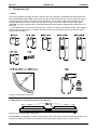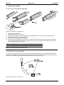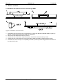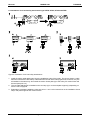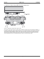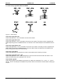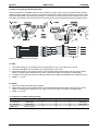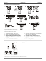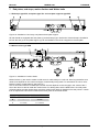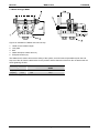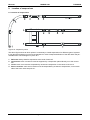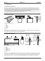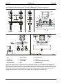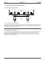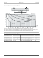
1
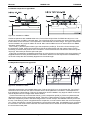
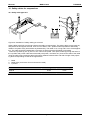
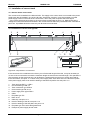
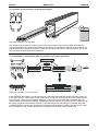
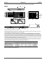
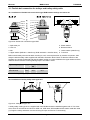
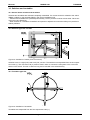
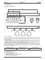
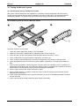
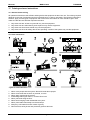
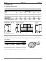
Movorail
Installation Manual
Edition: 4
DW110410gb-0710
Movorail
Version History
Edition Number
1
2
3
4
MARCH 2007
Edition Date
n.a.
n.a.
2005-02-18
2007-03-09
THOMSON
Reason for Revision
manual created
Changed content
Changed content and new style
Added instruction for adjustment of bogie trolleys
DANAHER MOTION is a registered trademark of Danaher Corporation. Danaher Motion makes every attempt to ensure accuracy and reliability of the specifications in this publication. Specifications are subject to
change without notice. Danaher Motion provides this information "AS IS" and disclaims all warranties, express or implied, including, but not limited to, implied warranties of merchantability and fitness for a particular
purpose. It is the responsibility of the product user to determine the suitability of this product for a specific
application.
2
DW110410gb-0710 Edition: 4
Installation Manual
Movorail
MARCH 2007
THOMSON
©2005 Danaher - Printed in Sweden. All rights reserved.
Table of contents
1.
Introduction ...............................................................................................................................................5
2.
The components of the Movorail system ...............................................................................................6
2.2
3.
Single girder systems ................................................................................................................................... 7
The Movorail rails .....................................................................................................................................8
3.1
3.2
Rails.............................................................................................................................................................. 8
Attachment of reinforcement profile type SPF 135 ....................................................................................... 8
4. Connection of rails ......................................................................................................................................9
4.1
4.2
Connection of straight rails type SPR ........................................................................................................... 9
Connection of curves type SPB .................................................................................................................... 9
5. Service sections ........................................................................................................................................10
5.1
6.
Trolleys and accessories for trolleys ...................................................................................................11
6.1
6.2
6.3
6.4
6.5
6.6
6.7
6.8
7.
End stops type STP, end plates type TPL and end plate supports type EPF ............................................. 18
Motion limiters type BGR ............................................................................................................................ 18
Walter bolt type WBM ................................................................................................................................. 19
Location of suspension..........................................................................................................................20
8.1
9.
Trolleys ....................................................................................................................................................... 11
Installation of rail and trolley attachments type KFFB, KFKK, KFVS and KFSB ......................................... 12
Adjustment of bogie trolleys type BGV 300 HSE with support rollers ......................................................... 13
Cable trolleys type KBV, KBVA and KBVS ................................................................................................. 14
Pick up trolleys type STV5 and STVG5 ...................................................................................................... 15
Installation of motor trolleys type TMT ........................................................................................................ 16
Adjustment of centre of gravity on motor trolley type TMT.......................................................................... 16
Electrical connection and adjustment of motor trolleys type TMT ............................................................... 17
End plates, end stops, motion limiters and Walter bolts....................................................................18
7.1
7.2
7.3
8.
Installation and inspection of service sections type SSKT .......................................................................... 10
Location of suspensions ............................................................................................................................. 20
Suspensions............................................................................................................................................21
9.1
9.2
9.3
9.4
9.5
General about suspensions ........................................................................................................................ 21
Z-suspensions type DZ ............................................................................................................................... 21
I-beam clamps type VBKLA ........................................................................................................................ 21
Flexible suspensions type DBSU ................................................................................................................ 22
Adjustable suspensions type ASU .............................................................................................................. 22
10. Safety cables for suspensions ..............................................................................................................23
10.1
Safety cable type SLU ................................................................................................................................ 23
11. Installation of current track ...................................................................................................................24
11.1
11.2
11.3
11.4
11.5
General about current track ........................................................................................................................ 24
Installation of current track type SB ............................................................................................................ 24
Insertion of current track in to the Movorail profile ...................................................................................... 25
Connection of current tracks with current track connection type ATSK 5.................................................... 25
Electrical connection of current track with power supply track type ATSA 5 ............................................... 26
12. Flexible bolt connection for trolleys and trolley safety cable ............................................................27
12.1
12.2
12.3
Installation of flexible bolt connection for trolleys type BUB between trolley and crane rail......................... 27
Installation of trolley safety cable type SLV................................................................................................. 27
Installation of flexible bolt connection for trolleys type TBUB between trolley and crane rail ...................... 28
13. Crane distance trolley and distance girders ........................................................................................29
13.1
13.2
Flexible distance girder type DNS............................................................................................................... 29
Rigid distance girder type SD ..................................................................................................................... 29
14. Switches and turntables ........................................................................................................................30
14.1
14.2
14.3
General about switches and turntables....................................................................................................... 30
Switches type HXL and VXL ....................................................................................................................... 30
Turntables type VSL ................................................................................................................................... 30
15. Cable loop................................................................................................................................................31
15.1
Installation of cable loop ............................................................................................................................. 31
>>> Table of content continues on the next page.>>>
Installation Manual
DW110410gb-0710 Edition: 4
3
Movorail
MARCH 2007
THOMSON
Table of contents
16. Testing the Movorail system..................................................................................................................32
16.1
16.2
General about testing of the Movorail system............................................................................................. 32
Inspection points at a test of a Movorail system ......................................................................................... 32
17. Training and user instructions ..............................................................................................................33
17.1
17.2
General about training ................................................................................................................................ 33
User instructions ......................................................................................................................................... 33
18. Technical data .........................................................................................................................................34
18.1
18.2
18.3
18.4
18.5
4
Data for the Movorail profiles ...................................................................................................................... 34
Tightening torque for bolts .......................................................................................................................... 34
Load diagram for a rail with a single load.................................................................................................... 35
Technical data for current track type SB..................................................................................................... 35
Voltage drop in cables ................................................................................................................................ 36
DW110410gb-0710 Edition: 4
Installation Manual
Movorail
MARCH 2007
THOMSON
1. Introduction
Thomson Movorail is a light weight rail system made of extruded aluminium profiles for loads up to 600 kg
which is designed and manufactured by Danaher Motion to meet the latest national and international standards. Product quality is assured by our ISO 9001 certified quality system.
Read trough this manual carefully and study all the instructions supplied with the delivery of the components before starting the installation work.
Do not hesitate to contact us for more information.
Important!
• Read trough all installation instructions and all other diagrams and documents supplied with the delivery before commencing the
installation in order to ensure that the work is carried out in a safe manner.
• No mechanical, electrical or pneumatic equipment delivered by Danaher Motion may be modified or be used in any other way
than what is described in this manual without the written permission from Danaher Motion.
• Never walk or stand under a hanging load.
• Ensure that all ladders, lifting and climbing aids used during the installation are in good condition and that they are securely fastened.
• Make sure that only authorised people enter the working area.
• Never use any components that appear to be faulty or damaged. Replace them immediately with the components of the same
make and type.
• The system must be labelled with a clearly visible max. load sign.
• All operators of the system should be instructed in using the system safely before using it.
• Never work with any electricity or compressed air switched on during the installation.
• The Movorail system may not be used before it complies with the EEC Machinery Directive (89/392/EEC) with valid amendments if it is to be used within the EEC area. In such cases electrical equipment is a part of the system the system also must
comply with the demands in the Low Voltage Directive (72/23/EEC) and the directive for Electromagnetic Compatibility
(89/336/EEC) with valid amendments.
• All equipment, work and documentation must, for both the electrical, mechanical and pneumatic areas, comply with all relevant
national and international regulations, standards and EEC directives.
• Regular maintenance is necessary in order to obtain long life and to maintain a high safety level. Service instructions can be
found in the ”Movorail Service Manual” which is included in the delivery.
• Do not hesitate to contact Danaher Motion if you have any questions.
Installation Manual
DW110410gb-0710 Edition: 4
5
Movorail
MARCH 2007
THOMSON
2. The components of the Movorail system
2.1 System with main girder rails
Figure 1: system with main girder rails
1. I-beam clamps type VBKLA: used to suspend a rail directly to an I-beam.
2. Single main girder rail
3. Movorail rail: load carrying profile which comes in five sizes: SPR 85, SPR 125, SPR 160A, SPR 295B
and SPR 295W.
4. Flexible suspension type DBSU: suspension type that allows some misalignment between the I-beam
and the rail.
5. Locating pin: a pin that guides the rails at connections.
6. Reinforcement profile: a profile that is used to reinforce profile SPR 160A.
7. Bogie trolley: trolley with horizontal wheels for guidance that is used for hanging loads.
8. BUB: attachment between bogie trolleys, distance girders and rails.
9. Yoke: frame in which a hoist or other loads can be suspended.
10. Down shop rails: the non-moving rails to which the suspensions are attached.
11. Span: the c/c distance between two down shop rails.
12. Current track: rail with copper conductors installed inside of the Movorail profile.
13. Distance girder: two types exist, flexible or rigid.
14. End plate
15. End stop
16. Double main girder rails
17. Connection
6
DW110410gb-0710 Edition: 4
Installation Manual
Movorail
MARCH 2007
THOMSON
2.2 Single down shop rail
Figure 2: single down shop rail system
18.
19.
20.
21.
22.
23.
24.
Rail and trolley cable attachment (kit): components that fix cables to the end of a rail and a trolley.
Cable: the type of cable/hose determines the type of cable trolley.
Cable trolley
Crab trolley
Service section: a hatch that facilitates the service of trolleys and other components at long rails.
End stop
End plate support: a component used to attach the end plate to when the end stop is not placed in the
end of the rail.
Installation Manual
DW110410gb-0710 Edition: 4
7
Movorail
MARCH 2007
THOMSON
3. The Movorail rails
3.1 Rails
There are five different straight rail sizes, SPR 85, SPR 125, SPR160A, SPR295B (with reinforcement profile) and SPR295W (with welded reinforcement profile). Further to this sizes 85, 125 and 160A also comes
in a curved versions (SPB). The reinforcement profile SPF 135 can also be delivered separately and be
installed afterwards on top of a SPR 160A with the aid of the T-slot profile TSS to create a rail of type
SPR295B. The max. allowed load for each profile depends on the distance between the suspensions, see
point 18.3.
For installations to the T-slots of the rails there is a series of T-slot bolts in different lengths. Size TBM 8 is
used for SPR 85 while TBM 12 is used for the others. Note! Only this type of bolt may be used for attachments to the rail T-slots.
Figure 3: profiles and T-slot bolts
3.2 Attachment of reinforcement profile type SPF 135
Figure 4: how to secure the T-slot profile
At SPR295B or at installation of reinforcement profile in the reinforcement profile must be fixed so that it can
not move. Installing T-slot bolts on both sides of the reinforcement profile prevents it from moving.
8
DW110410gb-0710 Edition: 4
Installation Manual
Movorail
MARCH 2007
THOMSON
4. Connection of rails
4.1 Connection of straight rails type SPR
Figure 5: connection of straight rails
1.
2.
3.
4.
5.
6.
Assemble the connection.
Push the connection on to the rail.
Glue the locating pins to the rail using the glue supplied with the connection. Also see below table.
Push the other rail on to the locating pins.
Do not glue the locating pins in this end!
Pull over the connection (6) from the first rail to the other until the connection is exactly in the middle
and then tighten all bolts according to the table in point 18.2. Note! Keep in mind that each connection
must be supported by a suspension.
L (mm)
SPR 85
SPR 125 / SPR 160A / SPR 295B / SPR 295W
30
40
Table 1: projecting length of the locating pins
4.2 Connection of curves type SPB
Connection of curves is done the same way as for straight but with special curve connections (SK 85R/B
and SK 125/160AR/B). Note! Keep in mind that both the connections and the curve must be supported by a
suspension. This means that at least three suspensions must be used per curve.
Figure 6: connection of curved rails
Installation Manual
DW110410gb-0710 Edition: 4
9
Movorail
MARCH 2007
THOMSON
5. Service sections
5.1 Installation and inspection of service sections type SSKT
Figure 7: installation of service section
1. Suspend the service section using one suspension on each side. Maximum allowed distance (Lmax.) is
400 mm for SPR 85 and 500 mm for SPR 125 / SPR 160A.
2. Remove the indicated socket head cap screws.
3. Test the function of the hatch. Adjust if necessary. Put back the socket head cap screws.
4. Test the function of the section by running the types of trolleys that will be used trough the section.
5. The hatch can, when it is open, be completely removed by knocking out the hinge pins from the hatch to
the sides of the hatch.
10
DW110410gb-0710 Edition: 4
Installation Manual
Movorail
MARCH 2007
THOMSON
6. Trolleys and accessories for trolleys
6.1 Trolleys
Figure 8: trolleys
1. Crab trolleys: this type of trolley is used when only hanging loads (the force pointing downwards) shall
be moved i.e. as for hoists.
2. Bogie trolleys: this type of trolley is used when both hanging loads and lateral forces can be present,
i.e. as for crane rails or systems with curves.
3. Bogie trolleys with lower support rollers: this type of trolley can manage hanging loads, lateral
forces and upward forces.
4. Pick up trolleys: this type of trolley is used when a rail is equipped with current track. STV5 can be
used alone while STVG5 must be connected to another trolley with the help of the cardan joint, see
point 6.4.
5. Motor trolleys: this type of trolley is used to motorise the movement in X or Y direction and is available
in several speed versions.
6. Cable trolley: this type of trolley is used to move cables along a rail. The cable trolley is at the delivery
equipped with a cable clamp, a strap or a cable tie for round cables, flat cables or hoses.
Installation Manual
DW110410gb-0710 Edition: 4
11
Movorail
MARCH 2007
THOMSON
6.2 Installation of rail and trolley attachments type KFFB, KFKK, KFVS and KFSB
Figure 9: installation of rail and trolley attachments
1. Install the trolley cable attachment (a) to the installation holes of the trolley. The picture shows a cable
attachment with a flat cable clamp. Cable attachments with other clamp types exist, however, they are
all installed in the same way. Also install the motion limiter plate (b) to the trolley if a motion limiter will
be used (see point 7.2).
2. The rail cable attachment is installed on the end stop (a) or to the end plate support (b) depending on
how the rail is equipped.
3. Examples of complete installations. Also see point 7.1 and 7.2 for instructions on the installation of end
stops, end plate supports and motion limiters.
12
DW110410gb-0710 Edition: 4
Installation Manual
Movorail
MARCH 2007
THOMSON
6.3 Adjustment of bogie trolley type BGV 300 HSE with support rollers
Figure 10: adjustment of bogie trolley support rollers
The position of the support rollers on bogie trolleys type BGV 300 HSE must be checked after installation. If
the distance between the support rollers is less than 0,1 mm anywhere along the entire length of the rail the
roller positions must be adjusted. To adjust, loosen the lock screws (1) and turn the eccentric shaft of the
rollers (2) until the distance between the rollers is within the limit all along the rail. Tighten the lock screw
when the adjustment is done. The tightening torque of the lock screws should be 5 Nm.
Installation Manual
DW110410gb-0710 Edition: 4
13
Movorail
MARCH 2007
THOMSON
6.4 Cable trolleys type KBV, KBVA and KBVS
Figure 11: cable trolleys
Cable trolley type KBV + FB
Cable trolley type KBV + FB is intended to be used to flat cables.
Cable trolley type KBV + KUL
Cable trolley type KBV + KUL is intended to be used to round cables. The trolley must be completed with
cable clamps of type KK in suitable dimension. A maximum of two cable clamps can be installed to the trolley.
Cable trolley type KBVA + KUL
Cable trolley type KBVA + KUL is intended to be used to round cables. The trolley must be completed with
cable clamps of type KK in suitable dimension. As many cable clamps as needed can be installed to the
trolley as long as the load do not exceed 50 kg.
Cable trolley type KBVS
Cable trolley type KBVS is intended to be used to round cables which is fixed by the strap.
Cable trolley type KBV + KUL + SB
Cable trolley type KBV + KUL + SB is intended to be used to hoses that are fixed with the cable tie. The
cable tie accepts hoses with a diameter of 30 – 80 mm.
Cable clamps type KK
Cable clamps type KK are available in three sizes, for cables with a diameter of 10 – 16 mm, 17 – 25 mm
and 26 – 36 mm. The clamps are installed on top of each other in the maximum amount that the trolley type
accepts.
14
DW110410gb-0710 Edition: 4
Installation Manual
Movorail
MARCH 2007
THOMSON
6.5 Pick up trolleys type STV5 and STVG5
STV5 is intended for rail SPR 85 and can carry loads up to 50 kg. STV5 can be connected to other trolley if
needed. STVG5 comes in two versions, STVG5-125 for rail SPR 125 and STVG5-160A for SPR 160A, SPR
295 B and SPR 295W. This trolley must always be connected to another trolley via the cardan joint, which is
included in the delivery. Never exceed the current limits of the pick up brushes/current track, see point 18.4.
Figure 12: connection of pick up trolley
A. STV5
1. The load-carrying pin can be placed in any of the holes (h1, h2, or h3). Max. load = 50 kg.
2. The strain relief plate can be placed in any of the holes (h1, h2 or h3).
3. Adjustment screw for the contact pressure of the brushes. Adjust the brushes to ensure good contact.
Clean if necessary the brushes from any oxide. Connect the cable according to the below table.
4. If needed, connect STV5 to another trolley by means of the cardan joint MBE1B (not included in STV5).
5. Cable 4 × 1,5 mm2.
B. STVG5
1. Connect STVG5 to the load carrying trolley.
2. Adjustment screw for the contact pressure of the brushes. Adjust the brushes to ensure good contact.
Clean if necessary the brushes from any oxide. Connect the cable according to the below table.
3. Cable 4 × 1,5 mm2.
C. Connection of cable to pick up trolley
a
b
c
d
e
1 × 230 VAC
Earth (PE)
L1
N
L1
Earth (PE)
3 × 400 VAC
Earth (PE)
L1
L2
L3
Earth (PE)
Yellow / green
1
2
3
–
Cable lead
Table 2: connection of cable on pick up trolley
Installation Manual
DW110410gb-0710 Edition: 4
15
Movorail
MARCH 2007
THOMSON
6.6 Installation of motor trolleys type TMT
Figure 13: installation of motor trolleys
Installation order for motor trolleys.
1. Lower the drive wheel, see point 6.8.
2. Set the correct profile size, see point 6,8.
3. Connect possible trolley to the motor trolley
using the cardan joint. Use MBE1B if curved
rails are used and MBE3 if only straight rails
are used.
4. Insert the motor trolley into the rail.
5. Attach the load to the trolley (never attach any
load to the motor trolley itself).
6. Check the centre of gravity, see point 6.7.
7. Connect the supply and the motor.
8. Adjust the drive wheel contact pressure, see
point 6.7.
9. Test run, see point 6.8.
6.7 Adjustment of centre of gravity on motor trolley type TMT
Figure 14: centre of gravity adjustment
Adjust the counter weight so that the trolley hangs perpendicular.
16
DW110410gb-0710 Edition: 4
Installation Manual
Movorail
MARCH 2007
THOMSON
6.8 Electrical connection and adjustment of motor trolleys type TMT
Figure 15: connection and adjustment
1.
2.
3.
4.
5.
Connect the motor cable.
Adjust the spring pressure to obtain slip free drive wheel operation.
Set the eccentric screw to the correct position for the profile size being used.
If pneumatic release is being used, make sure the operating pressure is max. 5 bar.
Install the pneumatic release cylinder sensor bracket as shown.
Installation Manual
DW110410gb-0710 Edition: 4
17
Movorail
MARCH 2007
THOMSON
7. End plates, end stops, motion limiters and Walter bolts
7.1 End stops type STP, end plates type TPL and end plate supports type EPF
Figure 16: installation of end stop, end plate and end plate support
All rails should be equipped with end plates (1) and end stops (2) in both ends. If the end stop is installed a
bit from the end (3) an end plate support (4) can be installed in the rail as a support for the end plate.
7.2 Motion limiter type BGR
Figure 17: installation of motion limiter
Motion limiters (1) are used to create a buffer zone for cable trolleys in a rail end. How long the buffer zone
needs to be depends on the number and type of cable trolley being used. For information on how to calculate the number of cable trolleys, see point 15.1.
One or two holes needs to be drilled (the number of holes depends on the rail type) in the centre of the Tslot of the rail to be able to install the motion limiter. For drilling data, see the table below. On trolleys that
will work against a motion limiter there must be a motion limiter plate (2) installed. Also see point 6.2. Check
that no suspension bolts will be located at the same place as the motion limiter.
BGR 85
BGR 125 / BGR 160A
A
38 mm
60 mm
B
–
36 mm
ø
1 × 9 mm
2 × 13 mm
Table 3: drill measures for motion limiters
18
DW110410gb-0710 Edition: 4
Installation Manual
Movorail
MARCH 2007
THOMSON
7.3 Walter bolt type WBM
Figure 18: installation of Walter bolt and end stop
1.
2.
3.
4.
5.
Holder for the rubber bumper
Lock plate
Bolt
Walter bolt (bolt, washer and nut)
End plate screws (2×)
The Walter bolt is used to enhance the safety of the system, as it will make it impossible to push the end
stop out of the rail. See the table below for the position and the diameter of the hole. Do not deform the rail
when tightening the bolt.
SPR 85
SPR 160A / SPR 295B / SPR
295W
L (mm)
49
52
56
Ø (mm)
12,5
12,5
12,5
Table 4: drilling position of the hole for Walter bolts
Installation Manual
SPR 125
DW110410gb-0710 Edition: 4
19
Movorail
MARCH 2007
THOMSON
8. Location of suspensions
9.1 Location of suspensions
Figure 19: suspension points
The above figure shows at which points it is necessary to install suspensions for different types of systems.
It may also be necessary to use more suspensions in order to keep the deflection of the rails within the permissible limits. See the diagram in point 18.3.
1. Rail ends: always install a suspension at the ends of each rail.
2. Connections: each connection must be supported by a suspension placed directly on to the connection.
3. Curves: each curve must be suspended by at least one suspension in the centre of the curve.
4. Service sections: each service section must be suspended by at least two suspensions, one on each
side of the hatch. Also see point 5.1.
20
DW110410gb-0710 Edition: 4
Installation Manual
Movorail
MARCH 2007
THOMSON
9. Suspensions
9.1 General about suspensions
Never use any suspensions or fixing material in any other way than recommended in this manual. Check
that the beams and suspension points that will be used can carry the maximum load of the system (max.
load to lift + weight of system). Furthermore may no suspension be exposed to higher side forces than 10 %
of the permissible max. load. Tighten all bolts according to the table in point 18.2.
We recommend that each suspension and its attachments should be thoroughly inspected by someone
with adequate knowledge before the system is tested or used.
9.2 Z-suspension type DZ
Figure 20: installation of DZ
1.
2.
3.
4.
5.
Nut
Washer
Z-profile
Clamp
Bolt
Z-suspensions are installed directly to the T-slot in the rail and is attached to the roof or a roof beam. Max.
load for DZ 85 is 1000 N while DZ 125/160A manage 6000 N.
9.3 I-beam clamps typ VBKLA
Figure 21: installation of VBKLA
1.
2.
3.
4.
5.
6.
Nut
Washer
Sliding washer
Clamp
T-slot profile
Bolt
I-beam clamps are installed directly to the T-slot in the rail and are attached to a beam flange. Max. load for
VBKLA 85 is 1000 N while VBKLA 125/160A manage 6000 N. I beam clamps type VBKLA accepts a beam
flange thickness (L) from 5 – 20 mm. I-beam clamps type VBKLA can not be installed on a connection.
Installation Manual
DW110410gb-0710 Edition: 4
21
Movorail
MARCH 2007
THOMSON
9.4 Flexible suspensions type DBSU
Figure 22: installation of DBSU
Flexible suspensions are installed either to the T-slot of the rail (as shown for DBSU 85-100) or on a connection (as shown for DBSU 125/160A-600). Two of the bolts of the connection are used in the later case to
fit the bracket to the connection. The suspension is then attached to a beam flange. This type of suspension
can be installed in any angle in relation to the rail. Max. load for DBSU 85-100 is 1000 N while it for DBSU
125/160A –600 is 6000 N.
Fit the cube (1) and the spacer sleeve (2) to the suspension profile (3). Then fit the I-beam clamps (4) to
the suspension profile. Attach the suspension profile to the beam flange with the I-beam clamps. Fit the
bracket (5) to the Movorail profile or to the connection. Fit the bracket to the cube with the aid of the cylindrical pin (6). Secure the pin with the split cotter pins.
If this type of suspension is installed both directly on to the rail and on connections in the same system, the
supplied washers must be placed between the rail and the bracket on those suspensions installed directly
on the rail to keep the rail horizontally aligned over the whole length.
9.5 Adjustable suspensions type ASU
Figure 23: installation of ASU
Adjustable suspensions are installed either to the T-slot of the rail (A) or on a connection (B). Two of the Tslot bolts of the connection are used in the later case to fit the plate to the connection. The suspension is
then attached to a beam flange. This type of suspension can be installed in any angle in relation to the rail
and be adjusted 50 mm in height. Max. load is 6000 N.
Fit the socket head cap screw and the sleeve (1) to the suspension profile (2). Fit the two plates and the
adjustment screws (3) to the suspension profile. Then fit the I-beam clamps (4) to the suspension profile.
Attach the suspension profile to the beam flange with the I-beam clamps. At installations directly on the rail
the two T-slot bolts (5), which is supplied with the suspension, must be used to attach the rail to the suspension. There must also be a washer (6) between the nuts and the lower plate. At installations on a connection
the two bolts in the centre of the connection are used instead and no washer should be installed between
the nuts and the lower plate.
22
DW110410gb-0710 Edition: 4
Installation Manual
Movorail
MARCH 2007
THOMSON
10. Safety cables for suspensions
10.1 Safety cable type SLU
Figure 24: installation of safety cable type universal
Safety cables type SLU are used to enhance the safety of suspensions. The safety cable is put around any
safe point that can support the load, such as a roof beam. The L-profiles makes it possible to add safety
cables to a system at any time without any disassembly. The cable is 1,5 m long and is cut to fit the application. The cable should be installed with a minimum of slack so that the fall height is minimised.
Insert the L-profiles (a) one by one in to the T-slot of the profile. Then put the cable (b) trough the holes in
the L-profiles and put the cable around the safe point (beam, roof beam etc.) Connect the ends of the cable
using the cable locks. Install the cable locks with a distance between them and with a length of the projecting ends corresponding at least to the figure above.
1. Cable
2. Cable locks (a minimum of two locks must be used)
3. L-profiles
Rail
Cable designation
Cable diameter (d)
SPR 85
SLU4
4 mm
SPR 125 / SPR 160A / SPR 295B / SPR 295W
SLU6
6 mm
Table 5: cable diameter
Installation Manual
DW110410gb-0710 Edition: 4
23
Movorail
MARCH 2007
THOMSON
11. Installation of current track
11.1 General about current track
The current track is installed in the Movorail rails. The supply to the current track is connected to the power
supply track that is installed in one of the rail ends. Sometimes, however, it may be necessary to install
power supply tracks in both ends of the current track, due to the power required. See below figure.
Carry out the electrical connections to the current track as described in point 11.5. Make sure that the
voltage and current that will be transmitted in the current track lies within the permissible limits. See table in
point 18.4. A qualified electrician must carry out all electrical connections.
11.2 Installation of current track type SB
Figure 25: components to current track
If the current track is not delivered from factory cut to fit the total length of the rails, it may be necessary to
cut one of the current tracks to make the total track length the same as the total rail length. This operation is
also necessary as the track ends only can be fitted to a straight track end and not to a track end used for
track connections, see point 11.4. Never cut a power supply track. Also drill a hole in the aluminium profile
at the power supply track to be used for earthing of the Movorail profile. Also see point 11.5.
1.
2.
3.
4.
5.
6.
7.
8.
9.
10.
11.
12.
13.
24
Track end type EST 5 + LED 5
Current tracks type SB, cut
Track connection type ATSK 5
Current track type SB, uncut
Power supply track type ATSA 5
Cable
End plate type TPL
Place of cut
Cable clip, see point 11.5
Hole for earthing of the rail, see point 11.5
Hole for earthing of the end plate, see point 11.5
End plate type TPLH with cable gland PG16
Example of power supply at both ends
DW110410gb-0710 Edition: 4
Installation Manual
Movorail
MARCH 2007
THOMSON
11.3 Insertion of current track in to the Movorail profile
Figure 26: insertion of current track
The current track is inserted in to the grooves in the profile. Use the top grooves in SPR 125! Install the
current tracks before any trolleys are inserted into the profile. The track end of the first current track can be
slightly chamfered to simplify the insertion. Chalk can be used as lubricant to reduce the friction. Never use
any oil or silicone based products as lubricants.
11.4 Connection of current tracks with current track connection type ATSK 5
Figure 27: connection of current tracks
Insert the plastic pins LED 5 (1) in the track end (2). Attach the track end with the aid of the two screws (3)
to the end of the first current track / power supply track (4) and then insert the track into the profile until the
first connection. Insert the four insulation pieces (5) in to the first current track and put together the next
current track (6) with the first so that the insulation pieces enter both tracks. Snap on the five collars (7) over
the copper conductors and snap on the track connection plate (8) so that rails gets connected. Insert the
connection and the current track until the next connection and repeat the procedure until the whole current
track is installed. At last, install a track end on the finishing current track / power supply track.
Installation Manual
DW110410gb-0710 Edition: 4
25
Movorail
MARCH 2007
THOMSON
11.5 Electrical connection of current tracks with power supply track type ATSA 5
Figure 28: electrical connection of current track
The power supply track ATSA 5 has five connection points for cable clips. The two outer are for screw connection while the three in the centre are for pin connection.
Proper earthing is important for the safety. Connect earth to the pre-drilled M3 Hole in the end plate (1)
and to the profile (2). At every connection (3) an earth cable (4) should be installed over the connection in
order to earth the whole rail. This requires the drilling of a hole in the beginning of each rail and at each side
of a connection. Clean the end plate and the profile from any oxide and anodising before the earth leads are
connected to ensure good contact. Carry out the connections to the current track according to the figure and
the table. At last, affix a warning sign (5) at both ends of the rail.
If the track has been stored before it is installed, it may be need to be cleaned from oxide before it is used.
Spray along the track with a contact spray, e.g. Electrolube SOB, Scotch 1607 or equivalent. Let the spray
work for a while before using the track. Never spray with the power on.
A
B
C
D
E
Supply 1 × 230 VAC
PE
L1
N
L1
PE
Supply 3 × 400 VAC
PE
L1
L2
L3
PE
Cable with number leads
Yellow/green
1
2
3
Yellow/green
Cable with colour leads
Yellow/green
Brown
Black
Black/white
Yellow/green
Table 6: connection of power supply track
26
DW110410gb-0710 Edition: 4
Installation Manual
Movorail
MARCH 2007
THOMSON
12. Flexible bolt connection for trolleys and trolley safety cable
12.1 Installation of flexible bolt connections type BUB between trolleys and crane rail
Figure 29: flexible bolt connections type BUB
1. Split cotter pin
5. Plastic washer
2. Lock nut
6. Distance sleeve
3. Nut
7. Lower washer (chamfer up)
4. Upper washer (BUB 85 = chamfer up, BUB 125/160A = chamfer down)
8. T-slot bolt
BUB:s should always be used to attach a trolley to a rail, never replace them by another component. Also
always install the safety cable supplied with the BUB, see below. Note! Check so that the chamfer of the
washers are correctly positioned and that the plastic washer is not stuck between the upper washer and the
distance sleeve! Use the correct tightening torque. See table 7 below.
Tightening torque
BUB
85
BUB 125/160A
Dry threads
(Nm)
23,0
77,8
Oiled threads
(Nm)
20,6
69,7
Table 7: BUB tightening torque
12.2 Installation of trolley safety cable type SLV
Figure 30: safety cable type SLV
A trolley safety cable type SLV is supplied with each BUB and shall be installed together with it. Two sizes
exist, SLV4 for rail SPR 85 and SLV6 for SPR 125, SPR 160A, SPR 295B and SPR 295W. Install the cable
(1) trough the trolley and attach it to the rail using its loops and the two T-slot bolts (2).
Installation Manual
DW110410gb-0710 Edition: 4
27
Movorail
MARCH 2007
THOMSON
12.3 Installation of flexible bolt connections type TBUB between trolleys and crane rail
Figure 31: flexible bolt connection type TBUB
1. Nut
5. Plastic washer
9. Movorail profile
2. Washer 2 x
6. Beam whit pin
10. Trolley
3. Upper beam
7. T-slot profile
11. Trolley load attachment beam
4. Distance sleeve
8. Bolt
12. Movorail profile
TBUB:s are used to connect a trolley to a rail. Put the plastic washer (a) on to the trolley load attachment
and put the upper beam (b) in place. Then insert the T-slot profiles (c) which are put on the bolts (d) in to the
Movorail profile. Adjust the bolts (e) so that the beam with the pin (f) and the distance sleeved can be placed
on the bolts. Push up the Movorail profile and fix it to the trolley by means of the washers (i) and nuts (j).
Tighten the bolts with the correct torque. For dry bolts use 77,8 Nm and for oiled 69.7 Nm.
28
DW110410gb-0710 Edition: 4
Installation Manual
Movorail
MARCH 2007
THOMSON
13. Crane distance trolley and distance girders
13.1 Flexible distance girder type DNS
Figure 32: flexible distance girder type DNS
The flexible type of distance girder separates two crane rails of type SPR 125, SPR 160A, SPR 295B or SPR
295W. The rails may move around the BUB. The distance girder (a) is attached by two BUB:s 125/160A (b).
For installation of BUB 125/160A, see point 12.1.
13.2 Rigid distance girder type SD
The rigid type of distance girder separates two crane rails of type SPR 125, SPR 160A, SPR 295B or SPR
295W. The rails are fixed in relation to each other. Except from this the rigid type of distance girder is installed and functioning in the same way as the flexible with the exception that four T-slot bolts are used for
the attachment instead for two BUB:s.
Installation Manual
DW110410gb-0710 Edition: 4
29
Movorail
MARCH 2007
THOMSON
14. Switches and turntables
14.1 General about switches and turntables
Switches and turntables are delivered completely assembled. If a current track kit is ordered to the switch
(SBHX or SBVX) or the turntable (SBVS), then this is installed as well.
Switches and turntables are operated pneumatically. The air pressure must be at least 6 bar. We recommend only using filtered air.
When a switch or a turntable is installed it is important to adjust them so that the trolleys can pass them
without problems.
14.2 Switches type HXL and VXL
Figure 33: installation of switch (seen from above)
Switches come in a right (HXL) and a left (VXL) version. The switches are suspended from the six suspension holes (1). The connection rail (2) must be used in order to connect the rail system to the curved rail
section in the switch. This rail is 1000 mm long and is included in the switch delivery.
14.3 Turntables type VSL
Figure 34: installation of turntables
Turntables are suspended from the four suspension holes (1).
30
DW110410gb-0710 Edition: 4
Installation Manual
Movorail
MARCH 2007
THOMSON
15. Cable loop
15.1 Installation of cable loop
Figure 35: cable loop
Cable loop can be done with flat cable (1), round cable (2) or hose (2). The same calculations are used for
all types of cables and hoses to calculate the necessary number of trolleys, the buffer zone length and the
length of the cables.
Always check so that the trolleys roll on their wheels and not are lifted up in the rail by the cables or the
hose. Always use flexible cables or hoses which are made for continuos motion and that can withstand the
environment in question. If in doubt, contact your cable or hose supplier.
Select the conductor cross-section area with respect to the power that will be transmitted. Keep in mind
that long cables may result in a voltage drop that necessitates the use of a greater conductor cross-section.
See point 18.6. Avoid using cables with less conductor cross-section than 1 mm² as they may break due to
the forces acting on the cable.
Number of trolleys
Length of buffer zone
Length of cables
n = Lt / (Lh × 2)
Lb = n × Lv
Lc = Lt + Lb × 1,15
Lt = total length of travel for cables
Lb = length of buffer zone
n = necessary trolley quantity
Lc = length of cables (hoses) in the loop
Lh = loop height (600 – 800 mm is recommended)
Lv = length of cable trolley being used
Installation Manual
DW110410gb-0710 Edition: 4
31
Movorail
MARCH 2007
THOMSON
16. Testing the Movorail system
16.1 General about testing of the Movorail system
The system must be tested when the installation is completed. Follow all applicable instructions below.
Please note that national and international regulations may call for further tests. The test area should be
closed during all tests, only persons who are involved in the testing procedures may enter the area.
16.2 Inspection points at a test of a Movorail system
Figure 36: inspection of the system
1. Check the system against the drawing, if any is available.
2. Make sure the system is marked with an adequate number of max. load sign.
3. Check the span (a). Max. permissible parallel deviation between the rails is ± 2 mm.
4. Check so that there is no gap between the rails at the connections (b).
5. Check so that no rails are deformed or that they are subjected to any twisting or bending forces.
6. Check the tightening torque for all bolt connections, BUB;s, suspensions, connections and safety cables.
7. Test any electrical systems. Perform at least a continuity check of the bonding circuit, an insulation resistance test and a voltage test. Also make sure that the system is equipped with a lockable main switch
placed beside it and that warning signs for electrical equipment are applied.
8. Run the system without load. Check all functions. Adjust.
9. Run the system with 25 % overload. Check all functions. Check all critical components after the test,
especially bolt connections.
10. If rails of type SPR 295W are used, check so that there is no cracks in the weldings between the upper
and the lower rail.
11. At last, check all rail and trolley tolerances again. Adjust if necessary.
32
DW110410gb-0710 Edition: 4
Installation Manual
Movorail
MARCH 2007
THOMSON
17. Training and user instructions
17.1 General about training
All operators should have the sufficient training before the equipment is taken into use. The training required
depends on the type of equipment and has to be defined on a case to case basis. The following instructions,
however, apply to most types of equipment and are the basic information all users should be given. Also
make sure that all users fulfil the requirements below.
1.
2.
3.
4.
Only those who are at least 18 years old may use the equipment.
Only those who are authorised by their superiors may use the equipment.
Only those who have been trained may use the equipment.
Only those who know all safety devices and operating controls of the system may use the equipment.
17.2 User instructions
Figure 37: user instructions
1.
2.
3.
4.
5.
6.
7.
8.
9.
Never move people with the system. Never lift loads above people.
Never force loads that are stuck or jammed, to move.
Never apply overload to the system.
Avoid lifting loads higher than 1,5 m above floor level.
Never pull loads along the floor.
Never leave hanging loads unattended at any time.
Never push loads intentionally into the end stops.
Always try to lift loads from their centre of gravity.
Wear hard hat, safety shoes and protective gloves at all times.
Installation Manual
DW110410gb-0710 Edition: 4
33
Movorail
MARCH 2007
THOMSON
18. Technical data
18.1 Data for the Movorail profiles
SPR 85
SPR 125
SPR 160A
Material
SPR 295B
SPR 295W
SPF 135
Anodised extruded aluminium
Colour
Natural aluminium
X (mm)
85
125
160
295
295
135
C (mm)
68,8
71,5
73,5
73,5
73,5
70
4/5/6/8
4/5/6/8
4/5/6/8
4/5/6/8
4/5/6/8
3,6 / 4,6 / 5,6
97
333
812
1368
3700
556
3
5
7,8
14
14,1
6,2
11
18,6
28,7
51,5
51,5
22,8
70 000
70 000
70 000
70 000
70 000
70 000
Standard profile lengths (m)
4
Inertia (cm )
Weight / meter (kg/m)
2
Profile area (cm )
2
Modulus of elasticity (N/mm )
Table 8: profile data
Figure 38: profile dimensions
18.2 Tightening torque for bolts
The table is valid for both normal bolts and T-slot bolts. The bolt grade is normally embossed on the bolt
heads, see the figure below. We recommend using at least bolt grade 8.8. Use a calibrated torque wrench to
gauge the torque.
Bolt dimension
Grade
Zinc-pl. dry
Zinc-pl.
oiled
M6
8.8
9,4 Nm
8,4 Nm
M8
8.8
23,0 Nm
20,6 Nm
M10
8.8
45,1 Nm
40,4 Nm
M12
8.8
77,8 Nm
69,7 Nm
M16
12.9
319,6 Nm
286,3 Nm
Table 9: tightening torque for bolts
34
DW110410gb-0710 Edition: 4
Figure 39: bolt grade
Installation Manual
Movorail
MARCH 2007
THOMSON
18.3 Load diagram for a rail with a single load
Figure 40: diagram for max. recommended distance between suspensions at a single load
The diagram is based on a maximum deflection of 1/500 of the distance between the suspensions (Lmax.)
and shows the maximum recommended distance between the suspensions at a given load.
18.4 Technical data for current track type SB
Max. voltage
400 V
Current track conductor cross-section
9 mm²
Protection class
IP 21
Max. current track
55 A
Ambient temperature
-20°C – + 55°C
Max. current connection
25 A
Voltage drop
0,103 V / m @ 25 A
Max. current power supply track
25 A
Max. speed straight rails
2 m/s
Max. current pick up @ 60 % ED
10 A
Max. speed curved rails
0,5 m/s
Max. current pick up @ 100 % ED
6A
Table 10: technical data for current track
Installation Manual
DW110410gb-0710 Edition: 4
35
Movorail
MARCH 2007
THOMSON
18.5 Voltage drop in cables
Long cables may lead to a significant voltage drop that may lead to malfunctioning. To avoid this it may be
necessary to increase the conductor cross-section. The formulas below can be used to calculate the voltage
drop. If the voltage drop exceeds 5 % (Ufactor less than 0,95) of the nominal voltage, a larger crosssectional area is necessary.
Formula 1.
Uend = Ustart - (2 × L × R × Imax)
Formula 2.
Uend / Ustart = Ufactor
Formula 3.
Ufactor > 0,95 = OK
Ufactor < 0,95 = not OK
Imax
= max. current to be transmitted in cable
Ufactor = voltage drop coefficient
Uend
= voltage at the end of the cable
Ustart
= voltage at the start of the cable
L
= length of cable
R
= resistance per meter (see table below)
Conductor area
1 mm
0,0175
2
0,0116
2
0,0070
1,5 mm
2,5 mm
Table 11: resistivity
Example:
If:
Then:
Conclusion:
36
Resistance / meter (R)
2
Ustart = 24 V, L = 40 m, conductor area = 1,5 mm², Imax = 1,5 A
Uend = 24 - (2 × 40 × 0,0116 × 1,5) = 22,608 V
Ufactor = 22,608 / 24 = 0,94
0,94 < 0,95 = not OK, the voltage drop is to large
a larger conductor cross-section is necessary, e.g. try with 2,5 mm².
DW110410gb-0710 Edition: 4
Installation Manual
Movorail
MARCH 2007
THOMSON
- page intentionally left blank –
Installation Manual
DW110410gb-0710 Edition: 4
37
Movorail
MARCH 2007
THOMSON
- page intentionally left blank -
38
DW110410gb-0710 Edition: 4
Installation Manual
Movorail
MARCH 2007
THOMSON
- page intentionally left blank -
Installation Manual
DW110410gb-0710 Edition: 4
39
Movorail
MARCH 2007
THOMSON
Sales and Service
Danaher Motion products are available world wide through an extensive
authorised Distributor network. These distributors offer literature, technical
assistance and a wide range of models off the shelf for fastest possible
delivery.
Danaher Motion sales engineers are conveniently located to provide prompt
attention to customers' needs. Call the nearest office listed for ordering.
United Kingdom
Danaher Motion
Chartmoor Road, Chartwell Business Park
Leighton Buzzard, Bedfordshire
LU7 4WG; United Kingdom
Phone: +44 (0)1525 243 243
Fax:
+44 (0)1525 243 244
E-mail: [email protected]
France
Danaher Motion
C.P 80018
12, Rue Antoine Becquerel – Z.I. Sud
F-72026 Le Mans Cedex 2
France
Phone: +33 (0) 243 50 03 30
Fax:
+33 (0) 243 50 03 39
E-mail: [email protected]
Germany
Danaher Motion GmbH
Sales Office North
Wacholderstr. 40-42
40489 Düsseldorf
Germany
Phone: +49 (0) 203 9979 214
Fax:
+49 (0) 203 9979 3214
E-Mail: [email protected]
Italy
Danaher Motion srl
Largo Brughetti
I-20030 Bovisio Masciago
Italy
Phone: +39 0362 594260
Fax:
+39 0362 594263
E-mail: [email protected]
Danaher Motion GmbH
Sales Office South West
Brückenfeldstraße 26/1
75015 Bretten
Germany
Phone: +49 (0) 7252 97390 56
Fax:
+49 (0) 7252 97390 55
E-Mail: [email protected]
Sweden
Danaher Motion
Box 9053
SE-291 09 Kristianstad
Sweden
Phone: +46 (0) 44-24 67 00
Fax:
+46 (0) 44-24 40 85
E-mail: [email protected]
Danaher Motion GmbH
Sales Office South East
Kiesgräble 7
89129 Langenau
Germany
Phone: +49 (0) 7471 62 23 23
Fax:
+49 (0) 7471 62 23 26
E-Mail: [email protected]
Switzerland
Danaher Motion SA
La Pierreire 2
1029 Villars-Ste-Croix
Switzerland
Phone: +41 (0) 21 631 33 33
Fax:
+41 (0) 21 636 05 09
E-mail: [email protected]
40
DW110410gb-0710 Edition: 4
Installation Manual