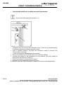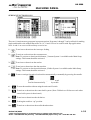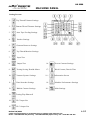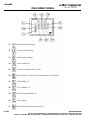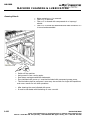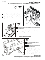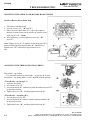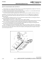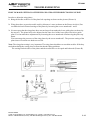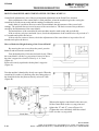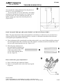
1
MODEL
LOCKWELT 6000
LOCKSTITCH POCKET WELT
MACHINE
PARTS AND SERVICE MANUAL
PART NUMBER 97. 6800.0.001
AMF is trademark of AMF Group, Inc.
10/2006
LIMITED WARRANTY ON NEW AMF REECE EQUIPMENT
Warranty provisions:
A ninety (90) day limited service labor warranty to correct defects in installation, workmanship, or material without charge for
labor. This portion of the warranty applies to machines sold as ”installed” only.
A one (1) year limited material warranty on major component parts to replace materials with defects. Any new part believed
defective must be returned freight prepaid to AMF Reece, Inc. for inspection. If, upon inspection, the part or material is determined to be defective, AMF Reece, Inc. will replace it without charge to the customer for parts or material.
Service labor warranty period shall begin on the completed installation date. Material warranty shall begin on the date the
equipment is shipped from AMF Reece, Inc.
Exclusions:
Excluded from both service labor warranty and material warranty are: (1) Consumable parts which would be normally considered
replaceable in day-to-day operations. These include parts such as needles, knives, loopers and spreaders. (2) Normal adjustment
and routine maintenance. This is the sole responsibility of the customer. (3) Cleaning and lubrication of equipment. (4) Parts
found to be altered, broken or damaged due to neglect or improper installation or application. (5) Damage caused by the use of
non-Genuine AMF Reece parts. (6) Shipping or delivery charges.
There is no service labor warranty for machines sold as ”uninstalled”.
Equipment installed without the assistance of a certified technician (either an AMF Reece Employee, a Certified Contractor, or
that of an Authorized Distributor) will have the limited material warranty only. Only the defective material will be covered. Any
charges associated with the use of an AMF Reece Technician or that of a Distributor to replace the defective part will be the
customer’s responsibility.
NO OTHER WARRANTY, EXPRESS OR IMPLIED, AS TO DESCRIPTION, QUALITY, MERCHANTABILITY, and FITNESS FOR
A PARTICULAR PURPOSE, OR ANY OTHER MATTER IS GIVEN BY SELLER OR SELLER’S AGENT IN CONNECTION HEREWITH. UNDER NO CIRCUMSTANCES SHALL SELLER OR SELLER’S AGENT BE LIABLE FOR LOSS OF PROFITS OR ANY
OTHER DIRECT OR INDIRECT COSTS, EXPENSES, LOSSES OR DAMAGES ARISING OUT OF DEFECTS IN OR FAILURE OF
THE EQUIPMENT OR ANY PART THEREOF.
WHAT TO DO IF THERE IS A QUESTION REGARDING WARRANTY
If a machine is purchased through an authorized AMF Reece, Inc. distributor, warranty questions should be first directed to that
distributor. However, the satisfaction and goodwill of our customers are of primary concern to AMF Reece, Inc. In the event that
a warranty matter is not handled to your satisfaction, please contact the appropriate AMF Reece office:
Europe
Prostejov, Czech Republic
Phone: (+420) 582-309-286
Fax: (+420) 582-360-608
e-mail: [email protected]
Warranty Registration Card
(Please Fax or Mail immediately after installation)
Note: All Warranty Claims Void, unless Registration Card on file at AMF Reece HQ
Machine model number:
(S101, S100, S104, S105, S211, Decostitch, S4000 BH,EBS Mark II, etc)
Manufacturer‘s serial or production number:
Installation Site Information:
Customer‘s Name:
Customer‘s Mailing Address:
Customer‘s Telephone Number:
Supervising Mechanic‘s or Technician‘s Name:
Signature of Supervising Technician:
AMF Reece Technician‘s Name:
AMF Reece Technician‘s Signature:
Type of garment produced at this location?
Average Daily Production Expected from this machine?
(number of buttonholes, jackets sewn, pants produced, buttons sewn, etc)
Any special requirements required at this location?
What other AMF Reece Machines are at this location?
How can we serve you better?
Tovární 837, 796 25 Prostìjov, Czech Republic
Fax: +420 582 360 606, e-mail: [email protected], website: www.amfreece.com
LW 6000
TABLE OF CONTENTS
PAGE
SAFETY
1. Introduction .................................................................................................1-1
2. General Safety Warnings ...............................................................................1-1
3. Safety symbols ............................................................................................1-2
4. Points to be especially considered by administration owner ..............................1-3
5. Maintenance personnel and specialized personnel ...........................................1-3
6. Specialized personnel ....................................................................................1-4
7. Proper use ...................................................................................................1-4
8. Technical data ..............................................................................................1-5
9. Actions to take in case of scraping the machine .............................................1-5
10. Transport, packing and storing ....................................................................1-6
11. Work symbols ............................................................................................1-7
ASSEMBLY
1. Assembling and preparing for first operation ...................................................1-8
2. Assembly .....................................................................................................1-8
3. Installing side supporting boards ....................................................................1-8
4. Installing vacuum (absorption) connection ......................................................1-9
5. Installing stacking module .............................................................................1-10
6. Installing sewing thread path .........................................................................1-11
FIRST COMMISSIONING
1. Switching on/off the machine ........................................................................1-13
2. Checking panel connection ............................................................................1-14
3. Preparing machine for sewing ........................................................................1-15
4. Inserting the needle .....................................................................................1-15
5. Winding (reels of) lower thread / tension adjustment of lower thread ...............1-16
6. Installing bobbin case & tension adjustment of lower thread ............................1-17
7. Attaching upper thread / tension adjustment of upper thread ..........................1-18
8. Replacing tape fleece band ...........................................................................1-19
PEDAL BUTTONS & FUNCTIONS
1. Functions of foot switch ................................................................................1-20
2. Standard functions of foot switch...................................................................1-21
MACHINE PANEL .................................................................................................. 1-22
Making Pocketwelts With Flap ............................................................................1-24
Making Regular Pocketwelts ...............................................................................1-25
Angle Normal Pocket Operation .........................................................................1-26
Making Slanted (Angle) Pocketwelts With Flapl ....................................................1-28
Normal Pocket Work By Using 8 Cycles ..............................................................1-30
Zipper Pocket Operation ....................................................................................1-31
Robot System Operation ...................................................................................1-32
Sewing function icons ........................................................................................1-33
Setting Screens ................................................................................................1-37
Top Thread Trimmer Settings ...........................................................................1-38
Bottom Thread Trimmer Settings ......................................................................1-38
Auto Tape Feeding Adjustments ........................................................................1-38
Released 10/2006
e-mail: [email protected]; [email protected]; website: www.amfreece.com
Phones: +420 582 309 146 (Service); +420 582 309 286 (Spare Parts); Fax: +420 582 360 606
LW 6000
TABLE OF CONTENTS
PAGE
Stacker Settings ...............................................................................................1-39
Garment Roller Settings ....................................................................................1-39
Top Thread Monitor Sensitivity Settings ..............................................................1-40
Input Test .......................................................................................................1-40
Output testl .....................................................................................................1-40
Testing Sewing Head and Motor ........................................................................1-41
Vacuum Settings ..............................................................................................1-41
Dart Stretcher Settings .....................................................................................1-41
Bobbin Length Settings .....................................................................................1-42
Testing the Flap Photocell ..................................................................................1-42
To run the test program ...................................................................................1-42
PLC Input List ..................................................................................................1-43
PLC Output List ................................................................................................1-44
Screen Contrast Settings ...................................................................................1-44
Work Counter, Date & Time Screen ...................................................................1-44
Information Screen ..........................................................................................1-45
Main Settings ...................................................................................................1-45
Marking Lihgts Settings .....................................................................................1-47
Corner Knife Settings ........................................................................................1-47
Clamp Settings .................................................................................................1-48
Saving Parameters ...........................................................................................1-48
Download Adjustment .......................................................................................1-49
Sew Motor (Efka) Parameters ...........................................................................1-49
Servo Parameters ............................................................................................1-49
Panel Parameters .............................................................................................1-50
Motor Errors on the PLC ...................................................................................1-50
Aditional Settings ..............................................................................................1-50
Photocell Selection and Connection .....................................................................1-52
Automatic Zipper Attachment System Settings ...................................................1-53
Angle Pocket System Enabled/Disabled ..............................................................1-53
Auto Loaders Enabled/Disabled ..........................................................................1-54
Cycle Operation by 8 Enable/Disable ..................................................................1-44
MACHINE CLEANING & LUBRICATING
1. Cleaning the machine....................................................................................1-55
2. Cleaning the hook and base ..........................................................................1-57
3. Checking oil level ..........................................................................................1-58
4. Air pressure setting of machine and cleaning pressure tube .............................1-58
5. Cleaning maintenance unit air filter .................................................................1-59
6. Lubricating clamp feet ...................................................................................1-61
7. Lubricating and cleaning the mechanisms on sewing machine ...........................1-61
8. Lubricating all joints and moving parts on stacking machine .............................1-62
9. Lubricating corner knife mechanism ...............................................................1-63
10. Periodical lubrication of machine ...................................................................1-63
Released 10/2006
e-mail: [email protected]; [email protected]; website: www.amfreece.com
Phones:+420 582 309 146 (Service); +420 582 309286 (Spare Parts); Fax: +420 582 360 606
LW 6000
SAFETY
1. INSTRUCTIONS
o
o
o
This machine has been produced in accordance with European Union directives
mentioned on Compliance and Manufacturer’s Declaration.
Do not neglect to consider general laws and other rules in force – also in the country of
operator – as well as law decrees and valid environment protection directives!
Always observe valid provisions of local professional organizations and other inspection
authorities.
2. GENERAL SAFETY WARNINGS
o
o
o
o
o
o
o
o
o
o
o
Machine may only be used by operators and technical specialists trained accordingly!
Safety rules and operating directions shall be read prior to operating the machine!
Danger and safety warnings about machine shall be taken into consideration!
Machine may only be operated in accordance with instruction and after taking protection
measures with this regard; in addition, all safety rules shall be taken into consideration.
While changing parts (for example needle, sewing foot and spool), inserting thread and
leaving the premises and during maintenance of machine, main switch of the machine
shall be shut down and unplugged!
Daily maintenance may only be performed by trained individuals!
During maintenance and repair regarding pneumatic hardware, machine shall be
disconnected from pneumatic power network! Exceptions are only valid for trained
specialist staff during adjustment and function control works!
Repair and special maintenance works may only be performed by specialist personnel or
trained personnel.
Works regarding electrical installations may only be performed by qualified specialists!
No operation may be performed on parts and hardware under tension! Exceptions are
according to directives regarding EN 50110.
Modifying the form of machine or other changes shall be made in accordance with safety
instructions.
•
Please use spare parts provided by AMF Reece for repair work! In cases where spare
parts and accessories other than provided ones are used, machine will not be
guaranteed by our AMF Reece. Installation and/or use of such products may affect
the formal specifications of machine in some cases. No responsibility is accepted due
to any damage arising from non original parts.
Revised 10/2006
e-mail: [email protected]; [email protected]; website: www.amfreece.com
Phone: +420 582 309 146 (Service), +420 582 309 286 (Spare Parts); Fax: +420 582 360 606
1-1
LW 6000
SAFETY
3. SAFETY SYMBOLS
Dangerous Part!
Points to especially pay attention!
Danger of injury for user or specialized personnel!
Dangerous part due to laser beam!
Warning!
1-2
Do not put your hand under mechanism and do not operate without safety
equipments. Switch off the main switch before inserting thread, changing
reel, changing and cleaning needle and etc.
Revised 10/2006
e-mail: [email protected]; [email protected]; website: www.amfreece.com
Phones: +420 582 309 146 (Service), +420 582 309 286 (Spare Parts); Fax: +420 582 360 606
LW 6000
SAFETY
4. POINTS TO BE ESPECIALLY CONSIDERED BY OWNER
•
This handbook is an integral part of the machine and must be easily accessibly by
user personnel.
•
Handbook must be read before commissioning the machine for the first time.
•
User staff members and specialized personnel shall be trained about protection
equipments of machine and safe working methods.
•
Owner shall only be obliged to completely operate the machine.
•
Owner shall ensure that no safety equipment is taken away or made inoperative.
•
Owner shall pay attention to employ only authorized individuals to work on the
machine.
•
Other detailed information is available at authorized dealer.
5. MAINTENANCE PERSONNEL AND SPECIALIZED PERSONNEL
•
•
•
•
•
•
•
Maintenance personnel
Maintenance personnel consists of individuals who are responsible from preparing the
machine for use, operating and cleaning the machine.
Maintenance personnel are obliged to observe the following points:
Safety measures in instructions manual shall be observed in all operations!
All kinds of operation modification which damage safety of machine shall be avoided!
Only authorized individuals shall be allowed to work on the machine!
Any change that may affect the safety of machine shall immediately be informed to
the owner!
Revised 10/2006
e-mail: [email protected]; [email protected]; website: www.amfreece.com
Phone: +420 582 309 146 (Service), +420 582 309 286 (Spare Parts); Fax: +420 582 360 606
1-3
LW 6000
SAFETY
6. SPECIALIZED PERSONNEL
•
•
•
•
•
•
•
Any individual professionally trained in Electrics/Electronics and Mechanics are
considered as specialized personnel. Such individuals are responsible for lubricating,
maintaining, repairing and adjusting the machine.
Specialized personnel shall be obliged to observe the following points:
He/she observe safety measures in instructions manual for all operations!
He/she switch off the main switch prior to adjustment and repair and shall take all
safety measures against switching on of the machine!
Operation with parts and equipments under tension shall be prohibited!
Exceptions are regulated by EN 50110 instructions.
Protection cover shall closed after repair and maintenance works!
7. PROPER USE
•
•
•
1-4
This machine is intended to be used for pocket stitching production in garment
industry.
Any use unauthorized by manufacturer shall be deemed as improper use.
Manufacturing company is not responsible from any damage which arises from
improper use!
Proper use includes use, maintenance, adjustment and repair measures defined by
the manufacturer!
Revised 10/2006
e-mail: [email protected]; [email protected]; website: www.amfreece.com
Phones: +420 582 309 146 (Service), +420 582 309 286 (Spare Parts); Fax: +420 582 360 606
LW 6000
SAFETY
8. TECHNICAL DATA
Speed:……………………………………………………………………………….2100 minutes-1
Length of Stitch:……………………………………………………….…………2,5 mm
Type of Stitch………………………....………………………………………….301
Needle System:…………………………………………………………………..134
Needle Size : ………………………....…………………………………………80 – 110 Nm
Stitching Motor:………………………………………..…See maintenance manual of motor
Electrical voltage ………………………………………..230 V, 50 – 60 Hz alternate voltage
Power requirement:…………………………………………………………….1,2 kW
Working air pressure:....…………………..………………………………….minimum 6 bar
Air consumption:……………………………..………………………………….about 5 3 /Time
Data on Noise:
Emission noise pressure level at 2000 minutes -1 stitching number at plant:…..LpA = 74 dB
(A)
(noise measurements acc.to DIN 45 635-48-A-1, ISO 11204, ISO 3744, ISO 4871)
Dimensions of Machine:
Length:about 1300 mm
Width:about 1350 mm
Height:about 1300 mm
Table height: 850 mm
Net weight: 234 kg
- Technical modifications are reserved.
- KpA = 2,5 dB
9. ACTIONS TO TAKE IN CASE OF SCRAPING THE MACHINE
•
•
•
•
•
•
Actions to take in case of scraping the machine.
Properly scraping the machine shall be borne by the customer.
Materials used in production of machine consist of steel, aluminum, brass and various
plastics.
Electrical installation is of plastic and copper.
Machine is scraped in accordance with provisions of regionally valid environment
protection legislation and possibly by the help of a private company.
Lubricated parts shall be removed in accordance with local environment protection
instructions.
Revised 10/2006
e-mail: [email protected]; [email protected]; website: www.amfreece.com
Phone: +420 582 309 146 (Service), +420 582 309 286 (Spare Parts); Fax: +420 582 360 606
1-5
LW 6000
SAFETY
10. TRANSPORT, PACKING AND STORING
•
Transport in delivery of machine to customer
•
Transport in delivery of machine to customer is not included in manufacturer’s warranty.
•
Please ensure that machine is only transported in straight form.
•
•
•
Disposal of Packing
Packing of machine consists of wooden crate, paper, cardboard and nylon.
Customer is responsible from proper disposal.
•
Storing
Machine may stored up to 6 months when not used. Machine shall be stored away
and humidity.
1-6
from dirt
Revised 10/2006
e-mail: [email protected]; [email protected]; website: www.amfreece.com
Phones: +420 582 309 146 (Service), +420 582 309 286 (Spare Parts); Fax: +420 582 360 606
LW 6000
SAFETY
11. WORK SYMBOLS
•
Detailed operations or important information are emphasized with symbols herein.
Symbols used herein shall have the following meanings:
•
Warning, Information
•
Cleaning, Maintenance
•
Lubricating
•
Maintenance, Repair, Adjustment,
(to be performed only be specialized personnel)
Revised 10/2006
e-mail: [email protected]; [email protected]; website: www.amfreece.com
Phone: +420 582 309 146 (Service), +420 582 309 286 (Spare Parts); Fax: +420 582 360 606
1-7
LW 6000
ASSEMBLY
1. ASSEMBLING AND PREPARING FOR FIRST OPERATION
•
After unpacking the machine, check if there is any damage due to transportation.
Please notify transporter and AMF REECE representative of any possible damage.
•
Machine must be assembled and operated by only qualified personnel! All
relevant safety regulations specified herein shall be strictly observed!
2. ASSEMBLY
•
Please ensure that convenient electricity and supply connections for compressed air
are available at the assembly place of machine (please refer to Technical Data,
Section 3).
• Machine should be lifted by forklift machine from transport pallet.
• Machine shall be lifted horizontally from the ground and shall be placed in the place of
assembly in a balanced manner on its four legs.
3. INSTALLING SIDE SUPPORTING BOARDS
•
Side Supporting Plate is mounted.
• Side Supporting Plate is attached to sewing machine table with screws nr. 2 in right
and left lugs.
1-8
Revised 10/2006
e-mail: [email protected]; [email protected]; website: www.amfreece.com
Phones: +420 582 309 146 (Service), +420 582 309 286 (Spare Parts); Fax: +420 582 360 606
LW 6000
ASSEMBLY
4. INSTALLING VACUUM (ABSORPTION) CONNECTION
•
•
•
Vacuum (absorption) connection;
Is inserted into hose bearings supplied with absorption and is fixed with clamp nr.1.
(This system is available in machines requiring vacuum installation).
Revised 10/2006
e-mail: [email protected]; [email protected]; website: www.amfreece.com
Phone: +420 582 309 146 (Service), +420 582 309 286 (Spare Parts); Fax: +420 582 360 606
1-9
LW 6000
ASSEMBLY
5. INSTALLING STACKING MODULE
•
Stacking module is screwed to the installation position on the leg of machine stand
through screw nr.2 (four screws).
• Pneumatic hoses are connected according to connection scheme.
1-10
Revised 10/2006
e-mail: [email protected]; [email protected]; website: www.amfreece.com
Phones: +420 582 309 146 (Service), +420 582 309 286 (Spare Parts); Fax: +420 582 360 606
LW 6000
ASSEMBLY
6. INSTALLING SEWING THREAD PATH
• Rod of sewing thread spool is installed as shown in the figure.
• Attach properly the thread reels to sewing thread spool.
Revised 10/2006
e-mail: [email protected]; [email protected]; website: www.amfreece.com
Phone: +420 582 309 146 (Service), +420 582 309 286 (Spare Parts); Fax: +420 582 360 606
1-11
LW 6000
FIRST COMMISSIONING
•
Turn the main switch nr.1 to switch on and off the machine.
Motor switch shall always be at position nr.2
•
•
•
•
•
•
•
If
1-12
Completely clean the machine and meanwhile check if there is any possible damage
at electricity cables and pneumatic connection hoses.
Check if available voltage is the same with connection voltage of machine (see
Technical Data of Machine).
In case of discrepancy, do not operate the machine!
Allow only specialists to connect the machine to the electric network.
Lubricate the machine or put lubricating oil in the machine. (See parts related to
Maintenance and Cleaning in Section 1).
Connect the machine to compressed air system.
Nanometer on the machine shall read air of 6 bars.
necessary, adjust this value (see section related to air pressure control/adjustment).
Revised 10/2006
e-mail: [email protected]; [email protected]; website: www.amfreece.com
Phones: +420 582 309 146 (Service), +420 582 309 286 (Spare Parts); Fax: +420 582 360 606
LW 6000
FIRST COMMISSIONING
1. SWITCHING ON/OFF THE MACHINE
•
•
•
•
Switch on main air inlet nr. 1
Check and if necessary, adjust air pressure.
Adjust air pressure to minimum 6 bars.
Switch on the Main Electricity Switch of machine (figure nr. 2) to ‘I’ position.
• Motor switch shown in figure nr. .shall always be in open position (I position).
• Turn the main switch to ‘0’ position (figure nr.2 ) to switch off the machine and main
air inlet (figure nr.1) must be closed.
Revised 10/2006
e-mail: [email protected]; [email protected]; website: www.amfreece.com
Phone: +420 582 309 146 (Service), +420 582 309 286 (Spare Parts); Fax: +420 582 360 606
1-13
LW 6000
FIRST COMMISSIONING
2. CHECKING PANEL CONNECTION
• If panel cable is not installed, socket nr.1 must be fixed in place and screwed as shown
in the figure below.
(One end of communication cable must be connected to COM2 socket and the other
end to communication socket of PLC inside Electronic control box).
1-14
Revised 10/2006
e-mail: [email protected]; [email protected]; website: www.amfreece.com
Phones: +420 582 309 146 (Service), +420 582 309 286 (Spare Parts); Fax: +420 582 360 606
LW 6000
FIRST COMMISSIONING
3. PREPARING MACHINE FOR SEWING
All preparation work must only be performed by authorized personnel!
4.
INSERTING THE NEEDLE
•
•
•
•
•
•
•
Shut down the machine! (Danger of injury in case of sudden operation of machine!)
Only use 134 DP 5 system needles!
Carrier Clamp Carriage must be placed at the back
Loosen screw nr. 1
Mount the part nr. 2 (needle) until the lowest part in its housing.
Groove of needles must be installed to face bobbin case.
Properly tighten screws nr.1.
Revised 10/2006
e-mail: [email protected]; [email protected]; website: www.amfreece.com
Phone: +420 582 309 146 (Service), +420 582 309 286 (Spare Parts); Fax: +420 582 360 606
1-15
LW 6000
FIRST COMMISSIONING
5. WINDING (REELS
LOWER THREAD
OF)
LOWER
THREAD/
TENSION
ADJUSTMENT OF
• Insert empty bobbins (part nr.1) into bobbin housing.
• Insert thread into thread path as shown in the magnified figure and wind clockwise for
once on bobbin
• Press arm (part nr.3) and operate the bobbin in direction of arrow.
• Bobbin (part nr.1) is automatically filled during sewing.
• Once bobbin is sufficiently filled (part nr.1), it automatically stops.
• Filling quantity of bobbin may be changed according to the adjustment of screw (part
nr.4) but the screw head (part nr.5) must be loosened for this.
•
1-16
After adjusting, screw head (part nr.5) must be tightened again.
Revised 10/2006
e-mail: [email protected]; [email protected]; website: www.amfreece.com
Phones: +420 582 309 146 (Service), +420 582 309 286 (Spare Parts); Fax: +420 582 360 606
LW 6000
FIRST COMMISSIONING
6 . INSTAL L ING BOBBIN CASE & TE NSION AD JUSTME NT OF LOW ER THRE AD
•
•
•
•
•
•
•
•
Shut down the machine to check and replace the bobbin case.
Pull bedplate to left and you will see the bobbin underneath.
Lift the arm (part nr. 1) upwards and remove the empty bobbin case.
Attach filled bobbin case to looper so that thread pulls off in the direction of arrow.
Close the arm (part nr.1)
Place the thread first to groove of bobbin case capsule (place nr.2) and then underneath the
thread spring.
Tension of lower thread is adjusted by turning the screw (screw nr.3).
Pull (close) bedplate sheet to left.
Revised 10/2006
e-mail: [email protected]; [email protected]; website: www.amfreece.com
Phone: +420 582 309 146 (Service), +420 582 309 286 (Spare Parts); Fax: +420 582 360 606
1-17
LW 6000
FIRST COMMISSIONING
7. ATTACHING UPPER THREAD / TENSION ADJUSTMENT OF UPPER THREAD
•
•
•
•
1-18
Switch of the machine.
Push bedplate sheet to left.
Insert completely both upper threads according to the graphic above.
Tension of upper thread is adjusted by turning knurl screws (parts nr. 1 and 2).
Revised 10/2006
e-mail: [email protected]; [email protected]; website: www.amfreece.com
Phones: +420 582 309 146 (Service), +420 582 309 286 (Spare Parts); Fax: +420 582 360 606
LW 6000
FIRST COMMISSIONING
8. REPLACING TAPE FLEECE BAND
•
•
•
Insert tape fleece band as shown in figure 9-05.
Operate the machine.
Find ‘cut and drive fleece band’ in any pocket program as shown in figure below:
Press the button ‘drive/cut tape functions’ (as shown in the figure above).
Tape is driven and cut.
Revised 10/2006
e-mail: [email protected]; [email protected]; website: www.amfreece.com
Phone: +420 582 309 146 (Service), +420 582 309 286 (Spare Parts); Fax: +420 582 360 606
1-19
LW 6000
PEDAL BUTTONS & FUNCTIONS
1. FUNCTIONS OF FOOT SWITCH
Functions of foot switch nr. 1:
-
If foot switch nr.1 is pressed when the machine is powered for the first time, Clamp carrier
system will drive itself to (front) Home Sensor.
It prepares the machine for sewing according to program and settings selected from machine
panel.
If clamp carriage is at the back and foot switch nr.1 is pressed, carriage comes forward.
Functions of foot switch nr. 2:
- It gradually returns functions made with foot switch nr.1.
If foot switch nr. 2 is pressed after starting to sew, sewing machine is urgently stopped.
1-20
Revised 10/2006
e-mail: [email protected]; [email protected]; website: www.amfreece.com
Phones: +420 582 309 146 (Service), +420 582 309 286 (Spare Parts); Fax: +420 582 360 606
LW 6000
PEDAL BUTTONS & FUNCTIONS
2. STANDARD FUNCTIONS OF FOOT SWITCH NR. 1.
Operation of foot switch:
1. Fabric Tension rod or Vacuum Motor is operated according to the selected position on control
display of machine.
2. Clamp carriage comes from back to front.
3. Clamp goes down (according to the selected position of control display of machine: Clamps
simultaneously or first to right and then to left or first to left and then to right)
4. Front folding manual goes down and folding sheets operate.
5. Cover holding arm operates (according to the selected position on control display of machine:
cover arms simultaneously or first to right and then to left or first to left and then to right)
6. Stitching is started.
Revised 10/2006
e-mail: [email protected]; [email protected]; website: www.amfreece.com
Phone: +420 582 309 146 (Service), +420 582 309 286 (Spare Parts); Fax: +420 582 360 606
1-21
LW 6000
MACHINE PANEL
When the machine is turned on, the first screen is AMF Reece logo.
It is necessary to touch any spot on the user friendly control panel to enter the main menu screen.
1-22
Revised 10/2006
e-mail: [email protected]; [email protected]; website: www.amfreece.com
Phones: +420 582 309 146 (Service), +420 582 309 286 (Spare Parts); Fax: +420 582 360 606
LW 6000
MACHINE PANEL
A - You can enter program number which is
desired to be worked.
LW-6000 comes with 10 main sewing
programs (20 in AP version).
Each program contains a further 4 pocket
styles providing a total of 40 memory presets
that can be programmed individually.
4 styles under each main program can be
used for cycle sewing different types of
pocketwelts.
Main programs 1 through 7 are used for regular pocketwelting.
Main programs 10, 11, and 12 are used for pocketwelting applications with flap.
Main programs 20 through 26 are used for angle pocketwelting. (Please note that you can only see these
programs on AP version LW-6000 machines.)
Main programs 30, 31, and 32 are used for angle pocketwelting applications with flap. (Please note that
you can only see these programs on AP version LW-6000 machines.)
It should be noted that each of the above programs have 4 pocket styles that can be preset for various
applications.
B - The arrow icon above the pocket styles shows the next welt style in the cycle sewing. Please press on
the number requested to move the arrow. (Please note that the selected pocket style needs to be in ON
position otherwise the machine will not sew.)
C - To change the cycle sewing sequence
of the 4 pocket styles. Some examples as shown below:
D - To activate the pocket styles required to be used
in the cycle sewing sequence . (Please note that at least
one pocket style Needs to be in ON position.)
Revised 10/2006
e-mail: [email protected]; [email protected]; website: www.amfreece.com
Phone: +420 582 309 146 (Service), +420 582 309 286 (Spare Parts); Fax: +420 582 360 606
1-23
LW 6000
MACHINE PANEL
Making Pocketwelts With Flap
A - Main programs 10, 11, and 12 are used for
Pocketwelting applications with flap. It is not
possible to enter a welt length manually because it will
be determined by the photocell
automatically. You will see the screen on the
right once you enter programs 10, 11, and 12.
B - To adjust the position of the start corner knife.
This parameter can be changed in multiples of 0.5 mm
to move the start corner cut inside or outside of the
welt.
C - To adjust the position of the stop corner knife. This parameter can be changed in multiples of 0.5 mm to
move the stop corner cut inside or outside of the welt.
D - The following screen will appear if you
press this icon.
E - To adjust the length of overlapping stitching
on the flap start. This parameter can be changed
in multiples of 0.5mm to adjust the stitching before
or after the flap start is detected by the photocell.
F - To adjust the length of overlapping stitching on
the flap finish. This parameter can be changed in
multiples of 0.5mm to adjust the stitching before or
after the flap finish is detected by the photocell.
G- Cover picture appearing on the left of panel
indicates that photocell connection on the left hand of
Photocell Section in Setup menu is activated or
Double Photocell connection is activated.
H- Cover picture appearing on the right of panel indicates that photocell connection on the right hand of
Photocell Section in Setup menu is activated or Double Photocell connection is activated.
1-24
Revised 10/2006
e-mail: [email protected]; [email protected]; website: www.amfreece.com
Phones: +420 582 309 146 (Service), +420 582 309 286 (Spare Parts); Fax: +420 582 360 606
LW 6000
MACHINE PANEL
Making Regular Pocketwelts
A - Main programs 1 through 7 are used for regular
Pocketwelting without flaps. (Please note that each of the 7
programs have 4 pocket styles that can be individually
programmed for various parameters.)
Using Active Marking Lights while making welts
B,C, & D can be used for selecting one of the three active
marking lights (front, rear and middle) for positioning of the pocketwelt on the
fabric. This eliminates the necessity of manual marking on the fabric panel and
increases the productivity of the operation. The marking lights on this machine is called “active” because
their positions can be changed from the control panel without physically moving them.
B - If selected the pocketwelt stitching will start from the position of rear marking light
C - If selected the pocketwelt stitching will be equally divided in both sides of the middle marking light
D - If selected the pocketwelt stitching will finish at the position of front marking light
In practical terms, the middle marking light is used as a guide
for trouser back pocket applications where as the front and
rear marking lights are used for jacket side pocket
applications. The marking lights are generally matched
against the dart seam on trousers or jackets.
E - The following screen will appear when you touch the
program information icon
F - You can adjust the length of the pocketwelt in between 25 mm and 195 mm.
G - Touching this icon opens the laser adjustments screen which enables the user to alter the active marking
lights position settings.
M - Normally the stitching would start at the position of
reaar marking light. It is possible to change the start position
and
icons in milimeters.
by pressing
N - Normally the stitching would finish at the position of front
marking light. It is possible to change the finish position by
pressing
and
icons in milimeters.
Revised 10/2006
e-mail: [email protected]; [email protected]; website: www.amfreece.com
Phone: +420 582 309 146 (Service), +420 582 309 286 (Spare Parts); Fax: +420 582 360 606
1-25
LW 6000
MACHINE PANEL
Angle Normal Pocket Operation
You can work the Angle Normal pockets at Program No :
20,21,22,23,24,25,26.
A – Program 20, 21, 22, 23, 24, 25 and 26 are the memory areas
reserved for Angle Normal pocket works. (There are 4 sub
programs under each program.)
You can sew the length of the pocket you would like to sew by
defining at “mm” unit type.
B – If you choose this laser, the sewing begins at the point where the
start laser points.
C – If you choose this laser, half of the sewing will be before the place where the middle laser points, and
half of the sewing will be after the middle point.
D – If you choose this laser, the sewing finishes at the place where the stop laser points.
E – When you touch the program information button, the screen on the left displays.
a- Shows the area that you enter on the program the length of the
Angle Pocket which will be sewn.
b- Shows the area that you enter the start and finish needle spaces of
the Angle Pocket which will be sewn.
When you touch this button, the screen on the left displays.
To set the beginning spaces (x) of the needles at the Start side ;
Button reduces the ‘x’ distance.
Button increases the ‘x’ distance.
‘E’ area shows the needle space in ‘mm’ unit.
Note: When the ‘E’ arrow shows ‘0’ or ‘1’ mm, the needles start to
work together, however the needles of 2mm and above start working
at different moments.
To set the finishing spaces (x) of the needles at the Finish side;
Button reduces the ‘y’ distance.
Button increases the ‘y’ distance.
‘F’ area shows the needle space in ‘mm’ unit.
Note: When ‘F’ arrow shows ‘0’ or ‘1’ mm, the needles finish together at
the end, however the needles of 2mm and above finish working at different
times.
c- When you touch this button, the following screen displays.
1-26
Revised 10/2006
e-mail: [email protected]; [email protected]; website: www.amfreece.com
Phones: +420 582 309 146 (Service), +420 582 309 286 (Spare Parts); Fax: +420 582 360 606
LW 6000
MACHINE PANEL
M - On normal conditions, the sewing begins at the place where the
laser points. If you would like to change the beginning location without
changing the place of the laser, you can benefit from this parameter.
You can change the beginning place of the sewing by using
(increases)
(decreases) buttons on the screen.
N - On normal conditions, the sewing ends at the place where the laser
points. If you would like to change the ending location
without changing the place of the laser, you can benefit
from this parameter.
You can change the ending place of the sewing by using
(increases)
(decreases) buttons on the
screen.
d- You can select the model of the start side of
the angle pocket you would like to sew here.
e- You can select the model of the finish side of
the angle pocket you would like to sew here.
Note: On the setup of the machine, when the Angle Pocket Covers are
activated, the start and finish labels above the “f” and “g” marked areas
continuously blink in order to show that these are active variables.
Note: The knife selection of the selected pocket model at the start and
finish sides is automatically chosen and activated by the machine.
You can select and work on the following angle pocket models here.
Revised 10/2006
e-mail: [email protected]; [email protected]; website: www.amfreece.com
Phone: +420 582 309 146 (Service), +420 582 309 286 (Spare Parts); Fax: +420 582 360 606
1-27
LW 6000
MACHINE PANEL
Making Slanted (Angle) Pocketwelts With Flap
The angle pocketwelting should be activated from Main Set-up Page
in order to work with main programs 30, 31 and 32.
A- Main programs 30, 31, and 32 are used for slanted pocketwelting
applications with flap. It is not possible to enter a welt length manually
because it will be determined by the photocell automatically. You will see
the screen on the left once you enter programs 30, 31, and 32.
The flap illustrations on the screen will appear on the right or left
depending on the which side the photocell is installed on the machine.
If the machine is equipped with both photocells, the flap will be seen or
left or right depending on the cycle sewing pocket style selected at the
moment which will enable the operator to make alternating left and right
welts.
E-The screen on the left will appear when you touch the program
information icon
a- To adjust the length of overlapping stitching on the flap start. This
parameter can be changed in multiples of 0.5mm to adjust the stitching
before or after the flap start is detected by the photocell.
b- To adjust the length of overlapping stitching on the flap finish. This
parameter can be changed in multiples of 0.5mm to adjust the stitching before or after the flap finish is
detected by the photocell.
c- To adjust the position of the start (rear) corner knife. This parameter
can be changed in multiples of 0.5 mm to move the start corner cut inside
or outside of the welt.
d- To adjust the position of the stop corner knife. This parameter can be
changed in multiples of 0.5 mm to move the stop corner cut inside or
outside of the welt.
e- Shows the place where we enter the Start and Finish needle spaces of
the Angle Pocket to be sewn.
When you touch this button, the screen on the left displays.
To set the beginning spaces(x) of the needles at the Start side;
Button reduces the ‘x’ distance.
Button increases the ‘x’ distance.
‘E’ area shows the needle space in ‘mm’ unit.
Note: When the ‘E’ arrow shows ‘0’ or ‘1’ mm, the needles start to work
together, however the needles of 2 mm and above start working at different
moments.
To set the finishing spaces(x) of the needles at the Finish side;
Button increases the ‘y’ distance.;
Button reduces the ‘y’ distance.
‘F’ area shows the needle space in ‘mm’ unit.
Note: When ‘F’ arrow shows ‘0’ or ‘1’ mm, the needles finish together at the
end, however the needles of 2 mm and above finish working at different times.
1-28
Revised 10/2006
e-mail: [email protected]; [email protected]; website: www.amfreece.com
Phones: +420 582 309 146 (Service), +420 582 309 286 (Spare Parts); Fax: +420 582 360 606
LW 6000
MACHINE PANEL
f-You can select the model of the start side of
the angle pocket you would like to sew here.
g- You can select the model of the finish side of
the angle pocket you would like to sew here.
Note: The knife selection of the selected pocket model at the start and finish sides is automatically chosen
and activated by the machine.
Note: On the setup of the machine, when the Angle Pocket Covers are activated, the start and finish labels
above the “f” and “g” marked areas continuously blink in order to show that these are active variables.
The Angle Pocket Covers are located on the left of the screen.
Because the photocell selection at the machine main setup occurs under the condition of right Photocell
Active or Double Photocell Active is chosen.
Note: When the Double Photocell is active, The cover picture is displayed on the right at cycle 2 and at
cycle 4.
Angle Pocket Covers are located on the left side.
Because The photocell selection at the machine main setup occurs as the condition of Photocell Active or
Double Photocell Active.
Note:
When the Double Photocell is active, the cover picture is displayed on the left at cycle 1 and at cycle 3.
Revised 10/2006
e-mail: [email protected]; [email protected]; website: www.amfreece.com
Phone: +420 582 309 146 (Service), +420 582 309 286 (Spare Parts); Fax: +420 582 360 606
1-29
LW 6000
MACHINE PANEL
Normal Pocket Work By Using 8 Cycles
After bringing 8 cycles into Enabled position and when we press information button indicated with “E”
on normal working screen, then following screen will come out in front of us.
You can write any program number
from 1,2... up to 7 instead of
program number indicated by “A”.
In similar way, a program number
from 1,2 .. up to 7 can be written
instead of program indicated by
“B”. So, sequence order work can
be assured between two programs.
Button indicated by (‘D’) must be
on Cycle OFF/ON, ON positions.
If Cycle ON/OFF button indicated by “D” is in OFF position, then “C” arrow will allow always left
program number to work and will prevent passing into right side.
Arrow indicated by ‘C’ will show program sequence order on which program number. If “D” will show
Cycle OFF/ON button is closed (if it is on OFF position), it will only make cycles on “A” side and will not
make cycles on “B” side.
FOR EXAMPLE: We want to make cycles between program 5 and 8 by program
1- Cycle OFF/ON button indicated by “D” must be on “Cycle ON” position.
2-
Let us assume that program will be in above-mentioned way.
3-When “C” arrow is touched it will show right or left side. (It will show whether program will start from
program number on right hand side of program or from program number on left hand side.)
4-If “C” arrow is selected as left side (if it starts from program 2)
1. Process line Program 2 Cycle E
2. Process line Program 2 Cycle G
3. Process line Program 2 Cycle H
4. Process line Program 5 Cycle K
5. Process line Program 5 Cycle L
6. Process line Program 5 Cycle M
5- If “C” arrow is selected as right side (if it starts from program 5)
1. Process line Program 5 Cycle K
2. Process line Program 5 Cycle L
3. Process line Program 5 Cycle M
4. Process line Program 2 Cycle E
5. Process line Program 2 Cycle G
6. Process line Program 2 Cycle H
Note: You may change cycle starting by touching any sub-program of program flow line in Cycle (X
arrow). But, that cycle must be in OFF position.
1-30
Revised 10/2006
e-mail: [email protected]; [email protected]; website: www.amfreece.com
Phones: +420 582 309 146 (Service), +420 582 309 286 (Spare Parts); Fax: +420 582 360 606
LW 6000
MACHINE PANEL
Zipper Pocket Operation
After making zipper system active on Setup screen;
Zipper
/
indicator shown by “A” can be adjusted at
different positions at desired each cycle pocket.
Zipper unit works on cycle pocket.
Zipper unit does not work on cycle pocket.
Programs where zipper pocket is used
Normal Flat Pockets:
Program Nr. 1,2,3,4,5,6 and 7
Note: Zipper Pockets can only be worked on normal pockets. They can not be used in Cover pockets and
Angle pockets.
If zipper system is selected on worked pocket (
), laser indicators shown by “C” and “D” will be out
of cycle and laser shown by “B” will become active.
If zipper system is selected on worked pocket (
), you can not make laser indicators shown by “C”
and “D” active.
Example: Program Nr. 2
1st Process = Program Nr. 2 Cycle 1 Zipper Active
2nd Proess = Program Nr. 2 Cycle 3 Zipper Active
3rd Process = Program Nr. 2 Cycle 4 Zipper closed
Revised 10/2006
e-mail: [email protected]; [email protected]; website: www.amfreece.com
Phone: +420 582 309 146 (Service), +420 582 309 286 (Spare Parts); Fax: +420 582 360 606
1-31
LW 6000
MACHINE PANEL
Robot System Operation
You can choose any of operation options for Robot System on icon
shown with ‚A‘.
All options can be adjusted in different positions for each Cycle
program.
Robot System does not work in Cycle pocket.
Left Robot loading system works on Cycle pocket.
Right Robot loading system works on Cycle pocket.
Left and Right Robot loading system works
on Cycle pocket.
Example Program:
Program Nr. : 1
1st Process Program Nr. : 1 Cycle 1 Robot System OFF
2nd Process Program Nr. : 1 Cycle 2 Left Robot System Active
3rd Process Program Nr. : 1 Cycle 4 Left and Right Robot
System Active
1-32
Revised 10/2006
e-mail: [email protected]; [email protected]; website: www.amfreece.com
Phones: +420 582 309 146 (Service), +420 582 309 286 (Spare Parts); Fax: +420 582 360 606
LW 6000
MACHINE PANEL
SEWING FUNCTION ICONS
There are 10 main memory programs in program options. Programs 1 through 7 can be utilized for making
single and double welts without flap where as 10, 11 and 12 are to be used for with flap applications.
Note: 8. and 9. are reserved for memory so not in use.
1-
To activate or deactivate the Auto tape feeding
2-
To activate or deactivate the vacuum motor
Note: To activate or deactivate this button, „Vacuum System“ is available under Main Setup
settings. This button should be activated.
3-
To activate or deactivate the stacker
4-
To activate or deactivate the dart stretcher
Note: To activate or deactivate this button, „Holder System“ is available under Main Setup
settings. This button should be activated.
5-
To move carriage forward to load position automatically or manually by pressing foot treadle.
Clamps move
Clamps move forward
Forward automatically
by treadle
6 -
To reset the machine without using the main on/off switch
7 -
To activate or deactivate the center knife system. (Note: Tab knives will also not work when
center knife system is deactivated.)
8 -
To activate or deactivate the tab knives.
9 -
To bring the needle to “up” position.
10-
To activate or deactivate the needle thread monitor.
Revised 10/2006
e-mail: [email protected]; [email protected]; website: www.amfreece.com
Phone: +420 582 309 146 (Service), +420 582 309 286 (Spare Parts); Fax: +420 582 360 606
1-33
LW 6000
MACHINE PANEL
11 -
To activate or deactivate the Bobbin counter.
12-
To Select if Main Clamps should go down automatically or manually by pressing foot
treadle to hold the fabric.
Clamps go down
automatically
13 -
Clamps go down
by treadle
To activate or deactivate backtacking or dense stitching at start and finish of stiching.
Backtacking
14 -
Dense stitch
To select activation and working sequence of flap clamps.
Flap Clamps
Flap clamp
Down at the same time
15 -
first right then left down
Flap clamp
first Flap Clamp
left then right down
right off Left activated
Main Clamps
first right then left down
16-
To activate Upper thread trimmer manually
17-
To activate lower thread trimmer manually
18-
To activate thread tension manually
19-
To activate auto tape feeding cutting manually.
20-
To activate stacker manually.
21-
To send carriage from front to back.
22-
To bring carriage from back to front
1-34
Flap clamp
both off
To select working sequence of Main Clamps
Main clamps
Down at the same time
23-
Flap Clamp
left off right activated
Main Clamps
first left then right down
Shows remaining thread length in left bobbin in “cm”. When the saved thread length by user is
over “bobbin finished” warning appears and machine stops. Press the icon and change the
bobbin.
Revised 10/2006
e-mail: [email protected]; [email protected]; website: www.amfreece.com
Phones: +420 582 309 146 (Service), +420 582 309 286 (Spare Parts); Fax: +420 582 360 606
LW 6000
MACHINE PANEL
24 -
To adjust backtacking and dense stitching parameters from the following screens
A - Dense stitch length in ‘mm’ at seam start.
B - Dense stitch length in ‘mm’ at seam end.
C - Definition area of close stitch for head revolution in rpm
D - Definition area for width of close stitch steps in mm.
A - Backtack length in ‘mm’ at seam start.
B - Backtack length in ‘mm’ at seam end.
C – Definition area of zig-zag stitch for head revolution in rpm.
D - Definition area for width of zig-zag stitch steps in mm.
25 -
The following screen appears when you select this icon for center knife settings for the pocket
style selected at the time.
A - To adjust the distance between seam start to center knife cut start in “mm”
B - To adjust the distance between seam end to center knife cut end in “mm”
Note: Correct Start and Finish settings of center knife ensure longevitiy of the corner knives and maximum
productivity.
Center knife settings should be adjusted according to the thickness of the fabric used.
Revised 10/2006
e-mail: [email protected]; [email protected]; website: www.amfreece.com
Phone: +420 582 309 146 (Service), +420 582 309 286 (Spare Parts); Fax: +420 582 360 606
1-35
LW 6000
MACHINE PANEL
26 -
To activate or deactivate the auto patch and flap loader Units.
No loaders available
Right auto loader available
Left auto loader available
right and left auto loader available
27 -
To activate or deactivate the zipper attachment unit.
Note: To activate or deactivate this button, „Zipper System“ is available under Main Setup
settings. This button should be activated.
28 -
Indicates if inclined pocket program is activated or deactivated under Main setup.
29 -
Activates or deactivates Roller system within program.
Note: To activate or deactivate this button, „Zipper System“ is available under Main Setup
settings. This button should be activated.
30-
To activate and deactivate brush blades
Right & Left Brush
Right brush blade active
Blade Active
left off
Left brush blade active
Right & Left Brush off
right off
It is general practice to activate both brush blades for double welt applications. De-activating left or right
blades depending on the single welt application side will help the quality of sewing especially if a larger
patch piece is in use.
31 -
To copy the parameters of the selected pocket style.
32 -
To paste the copied parameters to another pocket style available in main programs
33 -
Pressing this icon will open the main settings screen.
1-36
Revised 10/2006
e-mail: [email protected]; [email protected]; website: www.amfreece.com
Phones: +420 582 309 146 (Service), +420 582 309 286 (Spare Parts); Fax: +420 582 360 606
LW 6000
MACHINE PANEL
Setting Screens
1-
Top Thread Trimmer Settings
2-
Bottom Thread Trimmer Settings
3-
Auto Tape Feeding Settings
4-
Stacker Settings
5-
Garment Remover Settings
6-
Top Thread Monitor Settings
7-
Input Test
8-
Output Test
16-
Screen Contrast Settings
9-
Testing Sewing Head & Motor
17 -
Work Counter, Date & Time
10-
Vacuum System Settings
18 -
Information Screen
11-
Dart Stretcher Settings
19 -
Machine Performance Settings
12-
Bobbin Counter Settings
20 -
Main Settings
13-
Testing Flap Photocell
14 -
PLC Input List
15-
PLC Output List
Revised 10/2006
e-mail: [email protected]; [email protected]; website: www.amfreece.com
Phone: +420 582 309 146 (Service), +420 582 309 286 (Spare Parts); Fax: +420 582 360 606
1-37
LW 6000
MACHINE PANEL
1-
Top Thread Trimmer Settings
A - To set the trimming position of top thread after completion of sewing cycle. Adjustable in mm‚s in
relation to main clamp position.
B - To set the activation time of the top thread pick-up system.
C - To set the timing of the top thread release at start of sewing cycle.
2-
Bottom Thread Trimmer Settings
A - To set the the release position of bottom thread after start of sewing cycle. Adjustable in mm‚s in
relation to main clamp position.
B - To set the position of bottom thread pick-up and trim after completion of sewing cycle.
3-
Auto Tape Feeding Adjustments
A - To set the tape length at start of sewing
B - To set tape length at finish of sewing
Important Note: Please use non-sticky and medium thickness tape to ensure best results with your auto
tape feeding system
1-38
Revised 10/2006
e-mail: [email protected]; [email protected]; website: www.amfreece.com
Phones: +420 582 309 146 (Service), +420 582 309 286 (Spare Parts); Fax: +420 582 360 606
LW 6000
MACHINE PANEL
4-
Stacker Settings
A – To set the timing of stacker after sewing
cycle
B - To set the activation time of the stacker
Important Note: If you select a low parameter, the stacker can close before opening to its full extend
C – The stacker photocell is on. This photocell detects if the finished garment piece is moved out of the
machine by hand or a stacking system. The photocell ensures the main clamps stay at rear position if the
garment is still on the machine.
D - The stacker photocell is turned off.
5-
Garment Roller Settings
A - To set the start time of garment roller after
sewing cycle
B - To set the activation time of the garment
roller.
C - The garment roller is enabled. Please note
that the garment roller indicator in parameter
settings are also turned on/off from this icon.
D - The garment roller should be disabled if the system is not supplied with the machine.
Revised 10/2006
e-mail: [email protected]; [email protected]; website: www.amfreece.com
Phone: +420 582 309 146 (Service), +420 582 309 286 (Spare Parts); Fax: +420 582 360 606
1-39
LW 6000
MACHINE PANEL
6-
Top Thread Monitor Sensitivity Settings
A - To set the sensitivity on right thread
B - To set the sensitivity on left thread
The sensitivity of top thread monitor would be increased by lowering parameters A and B.
- Parameters A and B should be decreased if the machine does not stop despite a thread breakage
- Parameters A and B should be increased if the machine indicates a thread breakage eventhough the thread
is not broken.
C - To turn on the top thread monitor
D - To disable the top thread monitor. Top thread monitor indicator under sewing programs will display off.
7-
Input Test
To test sensors, switches and photocells that are on the machine.
8-
Output Test
To test the pneumatically activated mechanisms and motors on the machine
Screen 1 and 2: Exist in straight pocketwel machines
Screen 1 and 3: Exist in angle (slanted) pocketwelt machines
Screen 1 and 3: Exist in pocketwelting machines with automatic loaders
1-40
Revised 10/2006
e-mail: [email protected]; [email protected]; website: www.amfreece.com
Phones: +420 582 309 146 (Service), +420 582 309 286 (Spare Parts); Fax: +420 582 360 606
LW 6000
MACHINE PANEL
9-
Testing Sewing Head and Motor
This screen is to test the sewing motor and head.
A –To start and stop test cycle
B – To set the test speed
Important Note: Please make sure the top threads are
Taken off the needles before starting this test.
10 -
Vacuum Settings
A - To enable the vacuum system if this option is
Installed on the machine.
B - To disable the vacuum system. When
disabled the vacuum
Indicator under sewing programs is a
utomatically turned off,
11-
Dart Stretcher Settings
A - To enable the dart stretcher if this option is
installed on the machine
B - To disable the dart stretcher option. When
disabled the dart stretcher indicator under
sewing programs displays off
Revised 10/2006
e-mail: [email protected]; [email protected]; website: www.amfreece.com
Phone: +420 582 309 146 (Service), +420 582 309 286 (Spare Parts); Fax: +420 582 360 606
1-41
LW 6000
MACHINE PANEL
12 -
Bobbin Length Settings
A - To set the length of thread inserted into right bobbin in centimeters.
B - To set the length of thread inserted into the left bobbin centimeters.
Important Note: The bobbin thread length parameters decrease by the value of the pocket length in each
sewing cycle. If bobbin thread length indicator shows a lower value than the pocket length, the machine
does not operate and displays a warning.
13 -
Testing the Flap Photocell
A – This button activates a testing program for the flap photocell or photocells which detects the flap start
and finish on pocketwelting applications with a flap. In order to ensure an accurate operation, the photocell
needs to detect the reflector tape on the main clamps without an error. This section of the software is
dedicated to test this feature.
To run the test program
1 – When the test button is pressed and if the main
clamps are at rear position, there will be a warning
message on the screen.
Press A button (icon) to bring the clamps to front
position
2 - When the test button (icon) is pressed, the screen
will change to test mode if the clamps are in front position
1-42
Revised 10/2006
e-mail: [email protected]; [email protected]; website: www.amfreece.com
Phones: +420 582 309 146 (Service), +420 582 309 286 (Spare Parts); Fax: +420 582 360 606
LW 6000
MACHINE PANEL
A – Displays if right, left or both photocells are installed
And active on the machine
B – To start the test
Important Note: Please place a flat and clean piece of fabric
under the clamps before starting the test. The fabric should
be large enough to cover the area under clamp rubbers.
The clamp rubbers should not be in direct contact with the
main plate otherwise they can be worn out quickly due
to friction.
The following screen comes up when the test is
started
A - Displays if right, left or both photocells are
Installed and active on the machine
B – Displays the final status report about the
photocell test
Photocell is not
working well
Photocell is
working well
C – Displays the detection points on the reflector tape while the clamp is moving backwards. All the boxes
should be ticked to get a “Photocell is working well” message. One unticked box will activate a “Photocell
is not working well” message.
If you get a “Photocell is not working well” message
1 – Check the photocell and reflective tape is on the same direction…
2 – Ensure the reflective tape is un-deformed and clean
D – To pause the photocell test in a certain position. Pressing the button again will resume the test
E – To start test from beginning
F - Exit the Photocell Test Screen
14 PLC Input List
Informative screen showing numbers of input cables connected to PLC module in the control box.
Revised 10/2006
e-mail: [email protected]; [email protected]; website: www.amfreece.com
Phone: +420 582 309 146 (Service), +420 582 309 286 (Spare Parts); Fax: +420 582 360 606
1-43
LW 6000
MACHINE PANEL
15 -
PLC Output List
Informative screen showing numbers of output cables connected to PLC module in the control box
16 -
Screen Contrast Settings
A – To decrease backlight on the screen
B – To increase backlight on the screen
C - To save the last setting
17 -
Work Counter, Date & Time Screen
A – Shows time in hour:minute:second format
B – Shows the date in day:month:year format
C – Daily work counter
D – Total Work Counter
E – Total Work Hours
F – Resets number of works stitched per day at the machine.
1-44
Revised 10/2006
e-mail: [email protected]; [email protected]; website: www.amfreece.com
Phones: +420 582 309 146 (Service), +420 582 309 286 (Spare Parts); Fax: +420 582 360 606
LW 6000
MACHINE PANEL
18 –
Information Screen
This screen displays date, software version, and some other information about the machine
1 – Displays date in day/month/year format
2 – Displays software version of the control panel
3 – Displays version number of PLC system
4 – Displays needle type used on the machine
5 – Displays electrical requirements
6 – Displays air pressure requirement
19 -
This operation enables us to change operation
speeds of machine either upwards or downwards
at certain stages.
Selected level will directly effect performance of machine.
A - An upper level is selected button.
B - An lower level is selected button.
1.Level : Considering forwarding of clamp, entering speed of clamp into stitch, entering speed of clamp
into edge blades are at minimum, machine should be operated at the slowest level.
2.Level : At the outlet of factory, machine is loaded up to Level 2. Clamp actions are one step faster than
Level 1.
3.Level : Clamp actions are one step faster than Level 2.
4.Level : Clamp actions are upgraded to a quite high speed level compared to other Levels.
20 Main Settings
A password will be required to enter into this section of the software.
Please find overleaf the explanations of Main Setup settings.
Password : 11111111
Revised 10/2006
e-mail: [email protected]; [email protected]; website: www.amfreece.com
Phone: +420 582 309 146 (Service), +420 582 309 286 (Spare Parts); Fax: +420 582 360 606
1-45
LW 6000
MACHINE PANEL
21-
Marking Lights Settings
22-
Corner Knife Settings
23-
Main Clamp Settings
24-
Save Parameters
25-
Load Saved Parameters to PLC.
26-
Section Where Certain General Parameters are Available
27-
Efka PRM List
28-
Servo PRM List
29-
Panel Setting & PRM List
30-
311-46
Error Pages
Main Settings (Requires password).
Revised 10/2006
e-mail: [email protected]; [email protected]; website: www.amfreece.com
Phones: +420 582 309 146 (Service), +420 582 309 286 (Spare Parts); Fax: +420 582 360 606
LW 6000
MACHINE PANEL
21 -
Marking Lights Settings
A - Allows to adjust distance between the front marking light and the needle in mm’s
B – Allows to adjust distance between the middle marking lights and the needle in mm’s
C - Allows to adjust distance between the rear marking light outside and the needle in mm’s
D – To adjust the speed of the main clamp from sewing start to photocell detection point in pocketwelting
applications with flap
Note : Please refer to page XXX for sewing start and finish settings in relation to marking light positions
22 -
Corner Knife Settings
A - Allows to adjust distance between the needle
and Front Corner Knife in mm’s’
B - Allows to adjust distance between the Front
Corner Knife and Rear Corner Knife in mm’s’
Note : Adjustments ‘A’ & ‘B’ are used by AMF Reece technicians Please refer to page XXX for
operator corner knife settings
Note : Screen #1 will appear in straight welting machines Screen #2 will appear in slanted (Angle) welting
machines
Revised 10/2006
e-mail: [email protected]; [email protected]; website: www.amfreece.com
Phone: +420 582 309 146 (Service), +420 582 309 286 (Spare Parts); Fax: +420 582 360 606
1-47
LW 6000
MACHINE PANEL
23 -
Clamp Settings
A - To adjust the waiting time for the carriage before it comes back to the front of the machine after the
operation
B – To adjust speed of the carriage from back to front of the machine
C - To adjust speed of the carriage from front to the back of the machine
D - To adjust distance of the carriage to the back of the machine in mm’s
24 -
Saving Parameters
A – When pressed existing sewing functions and parameters are saved under the current pocket style
Backup button automatically saves your existing adjustments on the machine
You also can save the latest adjustments your self by pressing this button, too.
25 -
This is the section where general settings of machine are adjusted.
A – ??
B – To adjust tension closing time
1-48
Revised 10/2006
e-mail: [email protected]; [email protected]; website: www.amfreece.com
Phones: +420 582 309 146 (Service), +420 582 309 286 (Spare Parts); Fax: +420 582 360 606
LW 6000
MACHINE PANEL
26 -
Download Adjustment
A – When this button is pressed the BACK UP info is up loaded on the
For any reason if the machines settings are jammed you can return it to its previously saved correct settings
(which are BACKed UP before)
27 -
Sew Motor (Efka) Parameters
This is the info screen that lists parameters on the sewing motor.
28 -
Servo Parameters
This is the info screen that lists parameters on the servo motor.
Revised 10/2006
e-mail: [email protected]; [email protected]; website: www.amfreece.com
Phone: +420 582 309 146 (Service), +420 582 309 286 (Spare Parts); Fax: +420 582 360 606
1-49
LW 6000
MACHINE PANEL
29 -
Panel Parameters
This is the info screen to see the list of switches and parameters on the Panel
30 -
Motor Errors on the PLC
A – Button to eliminate and correct the motor errors on the PLC
It allows to see any error caused by external effects like voltage changes etc.
31 -
Aditional Settings
Entering this section will require a password.
Password : 15661566
1-50
Revised 10/2006
e-mail: [email protected]; [email protected]; website: www.amfreece.com
Phones: +420 582 309 146 (Service), +420 582 309 286 (Spare Parts); Fax: +420 582 360 606
LW 6000
MACHINE PANEL
33 -
Right Photocell, Left Photocell and Double Photocell Selection
34 -
Zipper System Enabled / Disabled Selection
35 -
Angle Pocket System Enabled / Disabled Selection
36 -
Robot Loading Enabled / Disabled Selection
37 -
Octave Cycle Operation Program Enabled/Disabled Selection
38 -
Private Chapter
39 -
Private Chapter
Revised 10/2006
e-mail: [email protected]; [email protected]; website: www.amfreece.com
Phone: +420 582 309 146 (Service), +420 582 309 286 (Spare Parts); Fax: +420 582 360 606
1-51
LW 6000
MACHINE PANEL
32 Photocell Selection and Connection
3 Different Variations of Photocell Connection and
Operation can be selected on the LW-6000.
1 – If there is only one flap photocell on the machine and if
the photocell is facing towards the left clamp foot
(Graphic A below), choose this option from the Main Setup
Screen (Graphic 1 on the right).
2 - If there is only one flap photocell on the machine and if
the photocell is facing towards the right
clamp foot (Graphic B below), choose this option from the
Main Setup Screen (Graphic 2 on the right).
3 - If there are both flap photocells installed on the machine and if
the photocells are facing towards both
clamp feet (Graphic C below), choose this option from the Main Setup
Screen (Graphic 3 on the right).
Note: Check to confirm that Right Photocell is connected to X6 jack on the PLC and Left Photocell is
connected to X12 jack on the PLC
1-52
Revised 10/2006
e-mail: [email protected]; [email protected]; website: www.amfreece.com
Phones: +420 582 309 146 (Service), +420 582 309 286 (Spare Parts); Fax: +420 582 360 606
LW 6000
MACHINE PANEL
33 -
Automatic Zipper Attachment System Settings
To alter these settings the machine must be equipped with an Automatic Zipper Attachment System
To begin operating the Zipper System, ‘ ZIPPER ATTACMENT ENABLED’ (A) must be set on the
screen
C- To adjust the activation time for the zipper feeder motor in order to allow enough zipper to be fed from
the roll through the special patch guide onto the fabric
D- To adjust timing for zipper cutter to move front, to stay
Activated, and to move backwards to its original position
E- To enable stacker photocell to control zipper cutter
For security reasons.
SUGGESTION: Keep this at ‘ON’ at all times.
34 -
Angle Pocket System Enabled/Disabled
To use this system your machine must be
manufactured with the ANGLE POCKET system
which includes a split needle sewing head and 6 sets
of corner knives.
To use Angle Pocket System press ‘ENABLED’ (A) position.
Revised 10/2006
e-mail: [email protected]; [email protected]; website: www.amfreece.com
Phone: +420 582 309 146 (Service), +420 582 309 286 (Spare Parts); Fax: +420 582 360 606
1-53
LW 6000
MACHINE PANEL
35 -
Auto Loaders Enabled/Disabled
To use this system your machine must be
manufactured with the Auto patch and flap loader
systems.
To use Loader System bring it to
‘ENABLED’ (A) position.
During operation times indicated with C-, operation
timings of actions are adjusted according to the automatic
receiving and loading unit process order of machine.
36 -
Cycle Operation by 8 Enable/Disable
To use this function bring it to ‘ENABLED’ (A) position.
1-54
Revised 10/2006
e-mail: [email protected]; [email protected]; website: www.amfreece.com
Phones: +420 582 309 146 (Service), +420 582 309 286 (Spare Parts); Fax: +420 582 360 606
LW 6000
MACHINE CLEANING & LUBRICATING
Cleaning entire machine …………………………………………………………………………..Weekly
Cleaning bobbin case section …………....……………………….......... several times per day
Checking oil level …………………………………...................... prior to operation everyday
Lubricating latch levers ………………………………………………….…………..... once a month
Checking air pressure …………………………........................ prior to operation everyday
Cleaning maintenance unit air filter ………………………..…………… whenever necessary
Time intervals for maintenance have been calculated according to average working time of machine at a
single shift factory.
In case machine is operated for more, it is highly recommended to keep maintenance intervals more
frequent.
1. CLEANING THE MACHINE
Time interval necessary for cleaning and lubricating the machine depends on the following
factors:
•
•
Single or multiple shift operation
Possibility of sewn material to get dusty
Revised 10/2006
e-mail: [email protected]; [email protected]; website: www.amfreece.com
Phone: +420 582 309 146 (Service), +420 582 309 286 (Spare Parts); Fax: +420 582 360 606
1-55
LW 6000
MACHINE CLEANING & LUBRICATING
It is recommended to carry out the following cleaning processes in order to prevent any operative
failures in single shift operations:
The entire machine must be cleaned for at least once a week.
1-56
Revised 10/2006
e-mail: [email protected]; [email protected]; website: www.amfreece.com
Phones: +420 582 309 146 (Service), +420 582 309 286 (Spare Parts); Fax: +420 582 360 606
LW 6000
MACHINE CLEANING & LUBRICATING
2. CLEANING THE HOOK AND BASE
Bobbin case section and needle part must be cleaned for several times per day.
o
o
o
o
o
o
o
o
o
o
Switch off the machine!
Turn of air pressure!
Remove screws nr.1
Remove base retainer nr.2
Turn hand pulley of head until base side stops horizontally at
capsule ventilator.
Remove base nr.3
Clean hook and base.
And lubricate thoroughly.
Insert spool capsule nr. 3.
Remove base retainer nr. 3.
Revised 10/2006
e-mail: [email protected]; [email protected]; website: www.amfreece.com
Phone: +420 582 309 146 (Service), +420 582 309 286 (Spare Parts); Fax: +420 582 360 606
1-57
LW 6000
MACHINE CLEANING & LUBRICATING
3. CHECKING OIL LEVEL
o
o
o
o
Switch off the machine!
Check oil level from window (figure nr.1) prior to operation every
day.
If oil is at lower level, it must be refilled until 1 oil level reaches
between upper and lower level on windows.
Use only 22,0 mm2/s oil with medium center
viscosity at 40°C and density of 0,865 g/cm3 at 40°C!
4. AIR PRESSURE SETTING OF MACHINE AND CLEANING PRESSURE TUBE
Air pressure setting of machine:
Air pressure must be checked with manometer prior to each
operation of machine.
• Manometer shall be adjusted according to air pressure of 6
bars. (Button nr.1 is pulled upwards and turned until
manometer reads pressure of 6 bars and button nr.2 is
pressed and fixed in place. Please see figure below).
•
1-58
Revised 10/2006
e-mail: [email protected]; [email protected]; website: www.amfreece.com
Phones: +420 582 309 146 (Service), +420 582 309 286 (Spare Parts); Fax: +420 582 360 606
LW 6000
MACHINE CLEANING & LUBRICATING
5. CLEANING MAINTENANCE UNIT AIR FILTER
Switch off the machine!
Remove compressed air pipe on maintenance unit.
Water container (figure nr. 1) is discharged.
Water container nr.1 is automatically discharged after
removing maintenance unit compressed air pipe.
Revised 10/2006
e-mail: [email protected]; [email protected]; website: www.amfreece.com
Phone: +420 582 309 146 (Service), +420 582 309 286 (Spare Parts); Fax: +420 582 360 606
1-59
LW 6000
MACHINE CLEANING & LUBRICATING
Cleaning Filter 2:
•
•
•
•
•
•
•
1-60
Water container nr.1 is removed.
Filter nr.2 is removed.
Filter nr.2 is cleaned with compressed air or isopropyl
alcohol.
Filter nr.2 is turned and assembled and water container nr.1
is turned and assembled.
Switch off the machine
And prevent it from running again.
Send clamp carriage mechanism backwards.
Zone indicated with arrow nr.1 must be lubricated with permanent grease pump.
This lubrication shall be performed once every two months for single shift operations
and once a month for two shift operations.
After cleaning the zone indicated with arrow
It must be lubricated with lubricating oil once a month.
Revised 10/2006
e-mail: [email protected]; [email protected]; website: www.amfreece.com
Phones: +420 582 309 146 (Service), +420 582 309 286 (Spare Parts); Fax: +420 582 360 606
LW 6000
MACHINE CLEANING & LUBRICATING
6. LUBRICATING CLAMP FEET
Clamp feet must be cleaned with air everyday and the zone indicated must be lubricated with machine
oil once a week.
7. LUBRICATING AND CLEANING THE MECHANISMS ON SEWING MACHINE
All lubricating holes on sewing machine and zones indicated with arrow must be properly wiped and
cleaned once a week and must be regularly lubricated.
Zones on sewing head must also be lubricated.
Upper thread cutting equipment must also be cleaned several times per day.
Touch ‘cut and hold thread’ sign on pocket programs, and clean waste thread parts
accumulated at the mouth of upper thread cutting mechanism.
Revised 10/2006
e-mail: [email protected]; [email protected]; website: www.amfreece.com
Phone: +420 582 309 146 (Service), +420 582 309 286 (Spare Parts); Fax: +420 582 360 606
1-61
LW 6000
MACHINE CLEANING & LUBRICATING
8. LUBRICATING ALL JOINTS AND MOVING PARTS ON STACKING MACHINE
All joints and moving parts on stacking machine must be properly cleaned with air everyday and
lubricated with machine oil for once a week.
1-62
Revised 10/2006
e-mail: [email protected]; [email protected]; website: www.amfreece.com
Phones: +420 582 309 146 (Service), +420 582 309 286 (Spare Parts); Fax: +420 582 360 606
LW 6000
MACHINE CLEANING & LUBRICATING
9. LUBRICATING CORNER KNIFE MECHANISM
Corner knife mechanism must be cleaned with air everyday and spindles and moving parts must be
lubricated with machine oil once a week.
10.
P E R I O D I C A L L U B R I C AT I O N O F M AC H I N E
Clamp Carrier and Clamps
GREASE
OIL
OIL
A-
You need to make oiling in 6 month periods with
grease oil.
B-
It is necessary first to clean and then to make normal
oiling in 3 month periods.
A
B
Revised 10/2006
e-mail: [email protected]; [email protected]; website: www.amfreece.com
Phone: +420 582 309 146 (Service), +420 582 309 286 (Spare Parts); Fax: +420 582 360 606
1-63
LW 6000
MACHINE CLEANING & LUBRICATING
GREASE
OIL
A&B-
C-
OIL
It is necessary first to clean and then to
make normal oiling in 3 month periods.
You need to make oiling in 6 month periods with
grease oil.
B
A
A
C
OIL
A-
It is necessary first to clean and then to make normal oiling in
3 month periods.
B-
It is necessary to continuously clean in 1 month periods and to
make normal oiling in 3 month periods.
B
Oil Inlets and Front of Section
A
D
C
OIL
B
A-
It is necessary to make oiling in 1
month periods.
B&C-
D-
E
1-64
It is necessary to make oiling in
3 month periods.
The oilbox "E" on top of the machine
head is the place I which normal oil is
added. When the oil level in the
Oilbox becomes lower than the
minimum required level, add oil to the
oilbox from the "D" point.
Revised 10/2006
e-mail: [email protected]; [email protected]; website: www.amfreece.com
Phones: +420 582 309 146 (Service), +420 582 309 286 (Spare Parts); Fax: +420 582 360 606
LW 6000
MACHINE CLEANING & LUBRICATING
GREASE
OIL
A
OIL
A-
It is necessary to clean in 1
month periods and to make
normal oiling in 3 month periods.
B-
It is necessary first to clean and
then to make normal oiling in 6
month periods.
C-
It is necessary first to clean and
then to make normal oiling in 6
month periods.
D-
It is necessary first to clean and
then to make normal oiling in 6
month periods.
E&F-
H-
B
E
C
It is necessary first to clean
and then to make normal
oiling in 6 month periods.
It is necessary first to clean and
then to make normal oiling in 3
month periods.
D
F
H
Clamp Carrier and Clamps
A
OIL
B
D
A-
B-
C-
DC
It is necessary first to clean and then to make normal oiling in 3 month
periods.
It is necessary first to clean and then to make normal oiling in 3 month
periods.
It is necessary first to clean and then to make normal oiling in 3 month
periods.
It is necessary first to clean and then to make normal oiling in 3 month
periods.
Revised 10/2006
e-mail: [email protected]; [email protected]; website: www.amfreece.com
Phone: +420 582 309 146 (Service), +420 582 309 286 (Spare Parts); Fax: +420 582 360 606
1-65
LW 6000
MACHINE CLEANING & LUBRICATING
A
A&B-
C-
It is necessary first to clean in one week
periods and then to make normal oiling
carefully.
It is necessary first to clean in one week periods and
then to make normal oiling carefully.
C
B
A
OIL
A-
B
C
1-66
It is necessary to clean in weekly periods
carefully.
B-
It is necessary first to clean and then to make
normal oiling in 3 month periods.
C-
It is necessary first to clean and then to make
normal oiling in 3 month periods.
D-
It is necessary first to clean and then to make
normal oiling in 3 month periods.
D
Revised 10/2006
e-mail: [email protected]; [email protected]; website: www.amfreece.com
Phones: +420 582 309 146 (Service), +420 582 309 286 (Spare Parts); Fax: +420 582 360 606
LW 6000
MACHINE CLEANING & LUBRICATING
Corner Knife , Top Thread Trimmer and Arm Thread Guide
OIL
A
A-
It is necessary to clean very well in 1 month periods and
then make normal oiling very carefully.
OIL
A-
It is necessary to clean in weekly periods and to make
normal oiling in 1 month periods.
A
OIL
A-
You need to make oiling with special silicone oil in 1
Month periods and replace the thread bag every month.
A
Revised 10/2006
e-mail: [email protected]; [email protected]; website: www.amfreece.com
Phone: +420 582 309 146 (Service), +420 582 309 286 (Spare Parts); Fax: +420 582 360 606
1-67
LW 6000
1-68
Revised 10/2006
e-mail: [email protected]; [email protected]; website: www.amfreece.com
Phones: +420 582 309 146 (Service), +420 582 309 286 (Spare Parts); Fax: +420 582 360 606
LW 6000
TROUBLESHOOTING
TABLE OF CONTENTS
Page
ADJUSTING THE NEEDLE AND ROTARY HOOK TIMING .................................. 2-2
ADJUSTING THE THREAD TENSION SPRING ........................................................ 2-2
ANGLE POCKET NEEDLE SYSTEM ADJUSTMENT ............................................... 2-3
CLAMP SETTINGS ........................................................................................................... 2-4
CLEARANCES BETWEEN ROTARY HOOKS AND PLATE ................................... 2-4
CRUCIAL POINTS WHEN ADJUSTING THE CENTRAL
GUIDE FOR THE FIRST TIME ...................................................................................... 2-4
HOW TO ADJUST THE BOTTOM THREAD CUTTER? .......................................... 2-6
HOW TO ADJUST THE END SEWING, IN THE BEGINNING
ON THE POCKET COVER AND AT THE END? ........................................................ 2-8
HOW TO ADJUST THE FRONT POSITION SHAPE OF THE CLAMP? ............... 2-8
HOW TO ADJUST THE LASER POINTERS? ............................................................. 2-9
HOW TO MAKE KNIFE CUTTING POSITIONS FROM THE PANEL? ................ 2-10
THE SOLUTION FOR THE CORNER KNIFE CUTTING PROBLEMS .................. 2-11
HOW TO MAKE PHOTOCELL SETTING? ................................................................. 2-12
HOW TO MAKE SETTINGS OF THE WING
PLATES OF THE DIRECTIONING GUIDE? ................................................................ 2-13
HOW TO MAKE THE ADJUSTMENT OF THE CENTRAL KNIFE’S? .................. 2-14
HOW TO MAKE THE SQUARE ADJUSTMENT
OF THE CENTRAL GUIDE? ........................................................................................... 2-15
INSTALLATION OF DOUBLE-SINGLE FILLET APPARATUS
TO THE MACHINE AND CLAMP SETTINGS ............................................................ 2-18
INSTALLING THE BOBBIN AND THE CUP .............................................................. 2-19
NEEDLE BAR HEIGHT ................................................................................................... 2-20
ROTARYHOOK TIMING ................................................................................................. 2-21
SENSOR SETTINGS OF HEAD POSITION SENSOR ................................................ 2-22
THE ISSUES TO BE TAKEN CARE OF ABOUT THE POCKET COVERS ........... 2-23
THE ISSUES TO BE TAKEN CARE OF ABOUT THE POKET COVERS ............. 2-24
THREAD SENSOR SENSITIVITY SETTING .............................................................. 2-25
Revised 10/2006
e-mail: [email protected]; [email protected]; website: www.amfreece.com
Phones: +420 582 309 146 (Service), +420 582 309 286 (Spare Parts); Fax: +420 582 360 606
2-1
LW 6000
TROUBLESHOOTING
ADJUSTING THE NEEDLE AND ROTARY HOOK TIMING
Needle to Rotary Hook Point Gap
1- Tilt back the machine head.
2- Loosen screws “A” , ”B” and “C”
3- Move the rotary hook base “1” to the left or right so
that the clearance between the needle “2” and the rotary
hook tip “3” is 1 – 3 mm.
4- After adjusting , securely tighten screws “A” , “B”
and “C”.
Note: Tighten screw “C” so that the lower shaft gear “5” is
gently touching the thread guide plate “6”. Furthermore ,
tighten screw “C” without moving it from its screw
stop.
ADJUSTING THE THREAD TENSION SPRING
Thread take – up tension
The standard tension for thread take – up spring “L 1” and
thread take – up spring “R 2” is o.15 – 0.35 N for both springs.
<Thread take – up spring L 1>
1- Open the face plate.
2- Loosen the screw “5”
3- Loosen the knob “6” , and then turn the threadtension stud “7”
to adjust the tension.
4- Tighten the screw “5” , and then tighten the knob “6”.
<Thread take – up spring R 2>
1- Loosen the set screw “8”
2- Loosen the knob “6” and then turn the adjustmentknob “9”
to adjust the tension.
3- Tighten the screw “8” , and then tighten the knob “6”
2-2
Revised 10/2006
e-mail: [email protected]; [email protected]; website: www.amfreece.com
Phones: +420 582 309 146 (Service), +420 582 309 286 (Spare Parts); Fax: +420 582 360 606
LW 6000
TROUBLESHOOTING
Operating range of thread – up spring the standart
Operating range for thread take – up spring “L 1” and thread take – up
spring “R 2” is 5 – 10 mm for both springs.
1- Loosen the left and right screws “3” and than turn the left and right
thread take – up spring stoppers “4” to adjust the operating range.
2- Tighten the screws “3”
Thread take – up spring operation timing.
The standart operation timing for thread take – up spring“R 2” is the
middle position within the operating range of the thread take – up spring
guide “10”
1- Loosen the screw “11”
2- Loosen the knob “6” , and then turn the left and right thread –
up spring guides “10” to adjust the tension.
3- Tighten the screw “11” , and then tighten the knob “6”.
ANGLE POCKET NEEDLE SYSTEM ADJUSTMENT
The piston must stand right in the middle at “0” point. To make the piston stay in the middle or to adjust its
stopping :
1-Bring the machine to one of the NORMAL POCKET (not angle) programs ( 1,2 ,3…7)
2-Springs number “a” and “b” control the piston to stop in the middle. The balance adjustment of the
springs is controlled by bearings “b” and “d”
3-When the piston is adjusted to stay on “0” point, the pin number “B” that controls the needles separate
motions must ,must be exactly on the line. If pn no “B” is not exactly at line “B” is even a little out side this
line split needle timings will not be correct while stitching.
Revised 10/2006
e-mail: [email protected]; [email protected]; website: www.amfreece.com
Phones: +420 582 309 146 (Service), +420 582 309 286 (Spare Parts); Fax: +420 582 360 606
2-3
LW 6000
TROUBLESHOOTING
CLAMP SETTINGS
Fabric folding gap between clamp and middle guide should
be between 0.5 mm and 1 mm according to the thickness
of fabric stitched.
It should be exactly the same from point A up to point B
between clamp and guide.
CLEARANCES BETWEEN ROTARY HOOKS AND PLATE
1 – Remove the slide plates.
2 – Tilt back the machine head.
3 – Loosen the set screws “9” and move the rotary hook “7”
up and down to adjust so that the clearance between
the rotary hook “7” and the needle plate “8” is 0.6 – 0.9 mm.
Note: Do not turn the rotary hook while the set Screws “9” are
loosened , otherwise it will change the timing between the needle
and the rotary hook.
4 – Tighten the set screws “9”.
CRUCIAL POINTS WHEN ADJUSTING THE CENTRAL GUIDE FOR THE FIRST TIME
1- If we refer to the sides of the needle plate when we assemle the central guide (Figure 13-A and B), the
guide has to be at equal distances to these two points. We can realize the right-left slip setting of the
guide to the desired direction (Right-Left) by loosening the C screw on the Figure 12.
2- The second crucial aspect of the central guide is how much the back of the guide needs to pass the
needle.
This distance (x) should be ‘minimum 2 mm’ , ‘maximum 3 mm’. (Figure 14)
2-4
Revised 10/2006
e-mail: [email protected]; [email protected]; website: www.amfreece.com
Phones: +420 582 309 146 (Service), +420 582 309 286 (Spare Parts); Fax: +420 582 360 606
LW 6000
TROUBLESHOOTING
Note: At this point, there is a very important point to be taken care
of. The knife protector of the guide should not hit the central knife ,
(the space shown by ‘y’ on Figure 14 should be minimum ‘2’mm) if
the “y” distance is less than 2mm, the central guide hits the central
knife while coming down and damages the knife, it also damages the
square of the guide and blocks the it to work properly. (Figure 14-y)
3- When the central guide comes down, the bottom of the guide and the bottom base should be parallel
and flat.(Figure 15 A and B point)
You can make the angle adjustment of the guide and the bottom base by the Z screw on the Figure 16.
The bottom of the guide should be parallel with the base.
Bottom space at thin works should be X = 1mm
Bottom space at middle works should be X= 1.5mm
Bottom space at thick works should be X= 2 mm
olmalidir.
Note: If the back and front ends of the central guide(Figure A-B points) are not at equal distance from the
base plate, your machine would collect and büzmek the fabric while you are sewing.
Revised 10/2006
e-mail: [email protected]; [email protected]; website: www.amfreece.com
Phones: +420 582 309 146 (Service), +420 582 309 286 (Spare Parts); Fax: +420 582 360 606
2-5
LW 6000
TROUBLESHOOTING
HOW TO ADJUST THE BOTTOM THREAD CUTTER?
At the end of the sewing, the threads coming from the bottom bobbin are cutted by the bottom cutter and
they are held in order for the threads not to be free.
The cutting process of the bottom thread is handled by the cylindrical stick shape steel knives which
are located inside the needle plate.
Important Issues While Making the Adjustments.
The normal position of the botton thread cutting knives inside the plate should be as shown on Figure
1) When your machine starts sewing, the botton thread cutting knives rotate 80 degrees counter clock wise
and take the flat position as shown on Figure 2, and at the end of the sewing, they again take their initial
position as shown on Figure 1. During this stage, the threads are being cut and held in order not to
become free.
You can test the thread cutting knives manually at the “A” button shown on Figure 3
2-6
Revised 10/2006
e-mail: [email protected]; [email protected]; website: www.amfreece.com
Phones: +420 582 309 146 (Service), +420 582 309 286 (Spare Parts); Fax: +420 582 360 606
LW 6000
TROUBLESHOOTING
Important Issues to be taken care of while Adjusting the Botton Thread Cutting Knife Inside the
Plate.
1 – Botton thread cutting knives must definitely be on the same level as the plate, and may even be very
little (0,2mm) below the top level of the plate.(Figure 1-2).
2 – Bottom thread cutting knives should not be adjusted to be higher or too much lower than the plate.
(Figure 4-5). If the bottom cutting knives are adjusted this way, your machine would collect the fabric
and it causes the stopping problem.
3 – By using the button “A” on the Figure 3, activate the bottom thread cutting knives manually and make
sure that the canal inside the knife and the thread way are adjusted correctly.
If few or a lot of canals are not in compliance (Figure 6), the thread might not be cutted, in this kind of
situation you can make your adjustments by loosening the screws shown by “B” on Figure 7. The final
position of your adjustment must be as shown on Figure 2.
Note: Please replace your bottom thread cutting knives periodically at least once a year or turn the cutting
axle upside down. Both bottom surfaces of the axles are convenient to be used as spare knives.
Revised 10/2006
e-mail: [email protected]; [email protected]; website: www.amfreece.com
Phones: +420 582 309 146 (Service), +420 582 309 286 (Spare Parts); Fax: +420 582 360 606
2-7
LW 6000
TROUBLESHOOTING
HOW TO ADJUST THE END SEWING, IN THE BEGINNING ON THE POCKET COVER
AND AT THE END?
Choose one of the Programs 10 , 11 or 12.
(Because the photocell scans the cover length in these
programs and the machine makes the cover’s beginning
and ending lengths automatically.)
1- On the cover being sewn, if the beginning sewing starts
inside the cover (Picture2), increase the ‘F’ parameter
on the image ‘1’ for the necessary distance. (every
point is= 0,5 mm)
2- On the cover being sewn, if the beginning sewing starts
outside the cover (Picture 3), decrease the ‘F’
parameter on the image ‘1’ for the necessary distance.
(every point is= 0,5 mm)
3- On the cover being sewn, if the ending sewing ends
inside the cover (Picture 4), increase the ‘G’
parameter on the image ‘1’ for the necessary distance.
(every point is= 0,5 mm)
4- On the cover being sewn, if the ending sewing ends
outside the cover (Picture 5), decrease the ‘G’
parameter on the image ‘1’ for the necessary distance.
(every point is= 0,5 mm)
HOW TO ADJUST THE FRONT POSITION SHAPE OF THE CLAMP?
Clamp finds the Home position when first turned on and stops. It is important
that the Clamp stays on the front.
The many positioning settings on the machine are directly related to this
setting. If the clamp stands on a different location than the one it should, it
might change all the settings completely and you might face many problems.
How to Make This Adjustment?
The distance between the needle and the clamp’s standing point in the front
after taking the home position should be exactly 305 mm (Figure 1).
If the clamp passes 305 mm and stands more in te front, slip the sensor
shown by “C” on Figure 18 on the direction of arrow “R” and adjust it by
necessary mm.
If the clamp stops before reaching mm, slip the sensor shown by “C” on
Figure 2 on the direction of arrow “F” and adjust it by necessary mm.
2-8
Revised 10/2006
e-mail: [email protected]; [email protected]; website: www.amfreece.com
Phones: +420 582 309 146 (Service), +420 582 309 286 (Spare Parts); Fax: +420 582 360 606
LW 6000
TROUBLESHOOTING
Note : While the linear cart stands on the front, the
distance between the position sensor should be ‘min :
1.5 mm - max : 2 mm. (Figure 2)
HOW TO ADJUST THE LASER POINTERS?
Machine starts and completes by referring to the place left by the laser point which is chosen on the panel.
That is why, the user places the material to be sewn under the machine, referring to these laser pointers.
Laser pointers are assemled and adjusted on the machine at standard distances from the needle. (Figure-1)
You can also see the places that the laser
pointers will leave, labeled on the base
plate of your machine. In case of any
adjustment change or loss of adjustment,
you can set the laser pointers to their
standard adjustment by benefitting from
here.
You can make this adjustent from the
“G” and “E” screw shown on Figure 1.
If you would like to adjust the clearity
of these laser pointers, you can adjust it
from the screw shown by “F”.
On some special applications, if you
would like to change the beginning and
ending locations of the sewing without
changing the location of the laser pointers,
you can take advantage of the parameters
shown by “H” and “I” on Figure 3.
(Technics Manual-Page XXX).
If you would like to make basic changes
on some measurements, you can benefit
from parameters shown by “C” and “D”
on Figure 2 under the control of a
technician. (Technics Manual-Page XXX).
Revised 10/2006
e-mail: [email protected]; [email protected]; website: www.amfreece.com
Phones: +420 582 309 146 (Service), +420 582 309 286 (Spare Parts); Fax: +420 582 360 606
2-9
LW 6000
TROUBLESHOOTING
HOW TO MAKE KNIFE CUTTING POSITIONS FROM THE PANEL?
No matter how long is the sewn pocket or the cover, the cutting position of the corner knives is realized
automatically by the machine.
The settings of the corner knife cutting positions of the sewn pockets are made from the Panel as shown
below.
B - You adjust the cutting position of the Start corner knife.
By changing the parameter, you can let in or out the position of the corner knife by multiples of 0.5 mm.
C - You adjust the cutting position of the Stop corner knife.
By changing the parameter, you can let in or out the position of the corner knife by multiples of 0.5 mm.
For example :
When the B parameter value is reduced, the Start corner knife proceeds inside the sewing. Shown by
the arrow labeled 1
When the B parameter value is increased, Start corner knife proceeds outside the sewing. Shown by
the arrrow labeled 3
When the C parameter value is reduced, Stop corner knife proceeds inside the sewing. Shown by the
arrow labeled 2
When the C parameter value is increased, Start corner knife proceeds outside the sewing. Shown by
the arrow labeled 4
2-10
Revised 10/2006
e-mail: [email protected]; [email protected]; website: www.amfreece.com
Phones: +420 582 309 146 (Service), +420 582 309 286 (Spare Parts); Fax: +420 582 360 606
LW 6000
TROUBLESHOOTING
THE SOLUTION FOR THE CORNER KNIFE CUTTING PROBLEMS
For the perfect and correct cutting of the corner knives at the pocket beginnings and ends;
1- It is necessary that the knife which cuts the center of the sewing is new and not rusty.
2- The settings of the middle knife which cuts the center of the sewings has to be correct and perfect.
Note: The problematic middle knife cuttings directly affect the corner knife cuttings and cause problematic
corner knife cuttings; because it cuts the fabric while gathering it and it creates sewing with breaks. And it
also causes the start corner knife to lose its position.
3- The corner knives need to be replaced periodically in periods of 2 to 4 months depending on the type of
the fabric. You cannot get perfect sewings with bad sewing quality knives.
After the above three main factors are conrolled, you will face the below problems in corner knife
cuttings.
Apply the mechanical solutions as described below;
Problem 1: Instead of dropping the corner knives at exact places, if it drops on the sewing by cutting one
of them, (Picture-2):
Solution: The screw of the corner knife cutting mechanism that cuts the sewings, shown with the arrow 5
has to be opened (Picture-1) and from the in/out adjustment screw shown by the arrow 6, you can adjust
the knife unit, on the opposite of cutted sewing direction.
Problem 2: The corner knives make angled cuttings to any direction instead of exact cuttings (Picture-4);
Solution: By opening the screw shown by the arrow 3 of the problematic corner knife mechanism that
makes angled cuttings, and making the adjustment by the sufficient angle, you can set the cutting angles
again.(Picture-1)
Problem 3: If the corner knives cut much less than they are suppossed to cut and the corner knife cut
apears to be too small (Picture-2) or if they cut too much than it has to and the corner knife cutting apears
to be too big (Picture-2);
Solution: Open the screw shown
with the arrow 4 (Picture-31) of
the knife unit which makes smaller
corner knife cuttings and lift the
knife piston unit a little bit up. If
the corner knife makes larger
cuttings, loosen the screw shown
by the arrow 4 (Picture-1) of the
problematic side and drop the
knife piston unit a little bit below.
Revised 10/2006
e-mail: [email protected]; [email protected]; website: www.amfreece.com
Phones: +420 582 309 146 (Service), +420 582 309 286 (Spare Parts); Fax: +420 582 360 606
2-11
LW 6000
TROUBLESHOOTING
HOW TO MAKE PHOTOCELL SETTING?
In the pocket cover sewings, the length of the cover is totally distinguished by the photocell. Therefore,
the setting of the photocell has to be very neat and perfect.
Firstly, it is necessary that the reflector strip on the clamp is scratchless, very clean and not deformed.
Do not forget that this strip has to renewed in 2-month periods.
It is necessary that from the beginning of the reflector strip at point A until the end of the reflector at
point B have to be taped. If the reflector strip is deformed at even a very slight degree, the photocell
perceives this deformed place during sewing and causes the cover to be on a different length than it is
suppossed to be.
After making sure that the reflector is very new and clean, the photocell has to be facing the reflector
strip perpendicularly with 90 degree angle. (point P )
When the photocell (item no 1) sees the reflector strip, orange led lights.
Photocell has to see the reflector strip from point A to point B of the clamp without turning off. If it does
not see it, check the strip and then check the facing angle of the photocell with the reflector strip.
You can check if the photocell can see the point A and point B on the Clamp by benefitting the test
screen on the page XXX and by moving the clamp manually.
If the viewing angle of the photocell and the reflector strip is not 90 degrees, adjust the viewing angle
from the screw shown by the arrow 2, behind the photocell. If the photocell still does not see the reflector
strip and it faces the side of the reflector, then you can adjust by moving the photocell right or left by the
screw shown by the arrow 3.
2-12
Revised 10/2006
e-mail: [email protected]; [email protected]; website: www.amfreece.com
Phones: +420 582 309 146 (Service), +420 582 309 286 (Spare Parts); Fax: +420 582 360 606
LW 6000
TROUBLESHOOTING
HOW TO MAKE SETTINGS OF THE WING PLATES OF THE DIRECTIONING GUIDE?
In order to adjust the wing plates;
1- Bring the needles to the level of the plate hole openings as shown on the picture.(Picture A)
2- Wing plates have to pass the needle ends by 0.8mm to 1 mm.(as shown on the Picture A with x) You
can make the back/forward settings of the plates by loosening the screws numbered 1 and 2.
3- It is necessary that the wing plates does not run longer from under the lower guide plate (as shown by
the arrow 5). The plates have to be adjusted on the same level of the lower part of the lower guide
plate. You can make these adjustments by loosening the screw numbered 4 and moving the plates up/
down.
You can arrange the pressures of the wing plates by the screw numbered 3. The pressure setting of the
plates has to be neither too hard nor too soft.
Note: The wing plate setting is very important. The wing plates should never touch the needles. If the they
touch them during the sewing, then it causes the thread cutting problems.
The settings on both sides of the plates and the needles have to be equal and balanced.(Picture B)
Revised 10/2006
e-mail: [email protected]; [email protected]; website: www.amfreece.com
Phones: +420 582 309 146 (Service), +420 582 309 286 (Spare Parts); Fax: +420 582 360 606
2-13
LW 6000
TROUBLESHOOTING
HOW TO MAKE THE ADJUSTMENT OF THE CENTRAL KNIFE’S?
Central knife adjustment is one of the most important adjustments at the Pockt Fleto Automat.
If the aadjustment of the central knife is with problems, when the machine begins the sewing the
central knife would not cut neatly and the cuttings would not be correct.
At this kind of a problem, the users tend to first müdahale the adjustments of the corner knife
cuttings. The problem does not occur because of the corner knives. The basic reason of the problem is
caused by the adjustments of the central knife.
The maintenance of the central knife in the machine must be made neatly and periodically.
If the works are polyester and with Lycra, check the adjustments of the central knives in periods of 2
or 3 months and replace the knives.
If the works are cotton or linnen, check the adjustments of the central knives in periods of 4 or 5
months and replace the knives.
How to Make the Height Setting of the Central Knife?
By entering the test screen from the panel, pass the
button A and activate the central knife.
Turn the hand pulley of the macine head slowly. When
the central knife is at the very top point, it has to be above
the plate’s toppest level and Z corner by 4 – 4.5 mm
(Figure-A)
It has to be exactly equalized with the plate’s top point
(Figure-A).
Turn the machine’s hand pulley slowly once again. When the
central knife is at the very bottom point, the cutting edge of
the should be below the plate surface by at least 0.5 mm
(Figure-B).
When replacing the central knife with a new one,
lift the central knife to the very top point and
tighten the “E” and “F” screws(Figure-19).
(Tighten the screws definitely when the central
knife is at the very top point).
2-14
Revised 10/2006
e-mail: [email protected]; [email protected]; website: www.amfreece.com
Phones: +420 582 309 146 (Service), +420 582 309 286 (Spare Parts); Fax: +420 582 360 606
LW 6000
TROUBLESHOOTING
You can make the cutting adjustment from the plate level
by the “K” screw on the figure 19.
If you loosen the “K” screw and lift the “M” handle,
cutting space slips up from the plate level. (Figure 20-U)
if you loosen the “K” Screw and take down the “M”
handle, cutting space slips down from the plate level.
(Figure 20-D)
HOW TO MAKE THE SQUARE ADJUSTMENT OF THE CENTRAL GUIDE?
Note : The gönya adjustment of the central guide has to be made by a technical service personnel or by
someone who has done a gönya adjustment before. And also, no fluctuation should be made unless the
central guide square adjustment is necessary.
1- Gönye adjustment of the central guide according to the needle is very crucial. If the parallelity setting of
the central guide and needle are not the same, there might be variations on the fleto width of the sewn
pockets at the beginning and at the end. (Figure 2 , 3)
2- When the gönye adjustment of
the central guide according to the
needle is correct, the fleto width
of the sewn pockets will be
correct at the beginning and at
the end. (Figure 1)
How to make these gönye adjustments?
1- Place a white A4 paper under the Clamps.
2- Draw a 3 cm long line on the side of the central guide.
(Figure 4)
Revised 10/2006
e-mail: [email protected]; [email protected]; website: www.amfreece.com
Phones: +420 582 309 146 (Service), +420 582 309 286 (Spare Parts); Fax: +420 582 360 606
2-15
LW 6000
TROUBLESHOOTING
3- From the test section on the panel(Technics Manual- Page XXX)
send the clamps back by 5-6 cm manually by the button shown
by ‘A’ .
4- Overview the parallelism of the the drawn line’s getting remote – closer from the central guide.(Figure 5)
5- After 5,6 cm, overview the location of the line once again.(Figure 6)
6- When the line comes to the rearest part of the central guide; (Figure 7)
2-16
Revised 10/2006
e-mail: [email protected]; [email protected]; website: www.amfreece.com
Phones: +420 582 309 146 (Service), +420 582 309 286 (Spare Parts); Fax: +420 582 360 606
LW 6000
TROUBLESHOOTING
If the line drawn on the paper goes parallel to the guide until the end of the central guide, it means
that the square adustment is correct.(Figure 8)
If the line drawn on the paper slips outside the guide instead of going parallel to the central guide
until the end of the guide (Figure 9), please rotate slightly the guide clockwise (arrow R) by loosening the
“A” and “B” screws on figure 11.
If the line drawn on the paper slips inside the guide instead of going parallel to the central guide
until the end of the guide (Figure 10), please rotate slightly the guide clockwise (arrow L) by loosening the
“A” and “B” screws on figure 11.
After these processes, check the correctness of the adjustments you have made by repeating the
whole operation.
Revised 10/2006
e-mail: [email protected]; [email protected]; website: www.amfreece.com
Phones: +420 582 309 146 (Service), +420 582 309 286 (Spare Parts); Fax: +420 582 360 606
2-17
LW 6000
TROUBLESHOOTING
INSTALLATION OF DOUBLE-SINGLE FILLET APPARATUS TO THE MACHINE
AND CLAMP SETTINGS
It is possible to use either double or single fillet apparatus basing on the pocket model to be stitched on the
machine. Double and single fillet apparatuses are changed by loosing screws A and B in Figure 2 and
installing other apparatus to housing C.
Note: Check if bottom part of apparatus is in parallel with main sheet after changing apparatus.
1 –Points “A” and “B” should be equally away from the ground.
2 –Clamps will be automatically located depending on the apparatus installed on the machine (machine
detects this as “D” sensor).
3 –assuming that we work with double fillet apparatus, clamps work basing on rings A2 and B1.
Note: Tensioning piston under clamps pull clamps to each other when double fillet apparatus is installed.
Tensioning piston under clamps separate clamps from each other when single fillet apparatus is installed.
Assuming that double fillet apparatus is replaced with left-hand expanded fillet apparatus, machine will
detect only single fillet apparatus and clamps will shift externally to lean on “Ay” ring.
“Ax” distance is as much as the excessive distance of single fillet apparatus.
Clamp based on A1 ring and left single fillet apparatus newly installed on the machine should be 0.5mm and
1mm away from the clamps on both sides. If such a distance is not possible, loosen ring A1 and take
necessary direction. In a like manner, if only right single fillet apparatus is installed, make necessary settings
from B2 ring position.
2-18
Revised 10/2006
e-mail: [email protected]; [email protected]; website: www.amfreece.com
Phones: +420 582 309 146 (Service), +420 582 309 286 (Spare Parts); Fax: +420 582 360 606
LW 6000
TROUBLESHOOTING
INSTALLING THE BOBBIN AND THE CUP
Installing The Bobbin
1 – Turn the machine pulley to raise the needle “1” to its
highest position.
2 – Insert the bobbin “2” into the rotary hook “3” so that
the winding direction is as shown in yhe illustration.
3 – Return the rotary hook latch “4” to its original
position.
4 – Turn the machine pulley to rotate the rotary hook “3”
until the tension spring “5” is visible.
5 – Pass the thread through slit A in the rotary hook and
then pass it under the thread tension spring “5”
6 – Pull out the thread to a length of approximately 50 mm
7 – Close the slide plates.
Installing The Cap
1 –Insert the bobbin “1” into the cap “2” so that the
winding direction is as shown in the illustration.
2 –Thread the thread by one of the following
methods in accordance with the shape of the cap being
used.
a) Pass the thread through slots A and under the tension
spring “3”
b) Pass the thread through slots B and C , and then
through the thread – loosening – prevention spring
“4”
c) Pass the thread through the thread hole “5” and pull
out about 50 mm
Revised 10/2006
e-mail: [email protected]; [email protected]; website: www.amfreece.com
Phones: +420 582 309 146 (Service), +420 582 309 286 (Spare Parts); Fax: +420 582 360 606
2-19
LW 6000
TROUBLESHOOTING
NEEDLE BAR HEIGHT
1 –Change the stitch legth to the smallest possible
setting.
2 –Open the face plate.
3 –Turn the machine pulley to move the needle bar “12”
to its lowest position. Reference line a at the top of
the needle bar “12” must be aligned with the lower
edge of the needle bar supporter “13” at the time.
4 –Loosen the screw “14” and move the needle bar
“12” up and down to adjust the height.
5 –Tighten the screw “14”
6 –Turn the machine pulley and check that the needle
goes into the middle of the needle hole in the feed
dog.
7 –Remove the needle plate.
8 –Remove the feed dog.
9 –Set the stitch length to either 2 (approx. 2 mm) or 3
(approx. 3mm) on the scale, depending on the
model and specifications of the machine.(refer to the
table)
10 – Turn the machine pulley to raise the needle bar
“12” by H mm from its lowest position (refer to the
table below for the value for H).
11 – The reference line “b” on the needle bar “12” will
be aligned with the lower edge of the needle bar
supporter ”13”.
The rotary hook tip “15” must be aligned
With the center of the needle at this time.
12 – Tilt back the machine head , loosen the three
screws “16” , and then align the rotary hook tip
“15” with the center of the needle.
13 – Tighten the screws “16”
14 – The distance from the upper edge of the needle
hole to the rotary hook tip “15” must be 1 –1.5 mm
when the rotary hook tip “15” is aligned with the
center of the needle.
15 – Install the feed dog.
16 – Install the needle plate.
2-20
Revised 10/2006
e-mail: [email protected]; [email protected]; website: www.amfreece.com
Phones: +420 582 309 146 (Service), +420 582 309 286 (Spare Parts); Fax: +420 582 360 606
LW 6000
TROUBLESHOOTING
ROTARYHOOK TIMING
A – When needle rises 2.4 mm above from the bottom dead
point, pinhole of rotaryhook point should be 1-1.5mm above
pinhole.
B – When needle rises 2.4mm above from the bottom dead
point, if pinhole of çapnoz point is backwards or forwards
the needle, loosen screw B and align point of çagnoz with the
center of needle.
C – When needle rises 2.4mm above from the bottom dead
point, if rotaryhook point is at the same center with needle
but if the height between pinhole and rotaryhook point is not
1 – 1.5 mm, adjust needle axle so that it can move upwards
and downwards.
Rotaryhook is behind the needle, advance
rotaryhook by removing screws.
Needle pinhole is very lower than rotaryhook point, loosen screw
C and rise needle axle.
Revised 10/2006
e-mail: [email protected]; [email protected]; website: www.amfreece.com
Phones: +420 582 309 146 (Service), +420 582 309 286 (Spare Parts); Fax: +420 582 360 606
2-21
LW 6000
TROUBLESHOOTING
SENSOR SETTINGS OF HEAD POSITION SENSOR
1 –Position of stitching head is adjusted by sensor A in Figure 3. The distance between sensor A and
positioning part on gear pulley should be min = 1 mm , max = 1,5 mm (Figure 4 , x distance)
2 –Turn hand pulley of machine forwards so that needles face the top point (Figure 5 , arrow direction
“L” ). When needles reach the top point (Figure1 and Positions 2 , 1) take from the top point of needles
again in the same direction about 2 , 7 mm downwards and stop (Figure 1 and positions 2 , 2.). At that
point the center of part shown with “b” in figure 3 should be exactly against sensor A (Figure 5 , point
“O”) (necessary settings can be done with screws on “B”.)
Note: If slots on part “B” are not sufficient for settings, loosen motor connecting screw “E”
2-22
Revised 10/2006
e-mail: [email protected]; [email protected]; website: www.amfreece.com
Phones: +420 582 309 146 (Service), +420 582 309 286 (Spare Parts); Fax: +420 582 360 606
LW 6000
TROUBLESHOOTING
THE ISSUES TO BE TAKEN CARE OF ABOUT THE POCKET COVERS
Sewing Quality on the Pocket Cover Applications:
1-It depends on the technical spesifications of the machinery and the perfection of the settings.
2- It depends on the form of the cover and the production quality.
3- During sewing, the machine distinguishes the length of the cover when the photocell perceives the side
borders of the cover.
Therefore, the neatness of the side borders affects the quality of the work directly.
Model-1 is a correct example for the cover sewing and neatness of the side borders.
Model-2,Model-3,Model-4,Model-5, are good examples for the wrong cover and side sewings.
This kind of wrong cover sewings blocks the machine to perceive the cover length correctly, that way you
will get different results than the original length of the cover. While working with this type of incorrect cover
examples, do not change the machine settings unnecessarily. Solve the real problem (cover sewing quality)
first.
On the covers sewn from thin and delicate fabrics, always use interfacing or a hardener, a material to keep
the cover hard and thick, inside the cover which consists of two seperate parts. The place shown with an
arrow labeled A. This will provide the cover’s form to look neat and does not create puckering or waviness
on the cover during sewing.
Revised 10/2006
e-mail: [email protected]; [email protected]; website: www.amfreece.com
Phones: +420 582 309 146 (Service), +420 582 309 286 (Spare Parts); Fax: +420 582 360 606
2-23
LW 6000
TROUBLESHOOTING
THE ISSUES TO BE TAKEN CARE OF ABOUT THE POKET COVERS
How to Locate the Pocket Carrier on the Clamp?
The A and B stops on the clamp have a role on the beggining and the ending of the cover to be sewn
according to the work reference pointers(Lasers).
They are put under the clamps, according to the body reference lamps of the cover that is to be sewn.
According to the right and left position of the body that the cover is to be sewn, the cover is sewn on
the exact location on the body, benefitting the A and B leaning points.
The E and F leaning points on the clamp are the stops to be used to adjust the width of the cover by the
user after the sewing.
If you are working on a jacket pocket cover on the machine, put the cover on the left clamp,
If you are working on a pants pocket cover on the machine, put the cover on the right clamp, while
working.
When the pocket cover is being sewn on the right and left body(fabric), it is sewn by first leaning on the
A leaning point and then on the B leaning point, respectively.
When the cover is located on the clamp, the next action of squeezing the cover and holding arm is
activated, by pushing the pedal button.
Note: The rubber(R) under the holding arm here has to be necessarily clean and neat. The cover held by an
incorrect rubber, might slip and the sewing is done with breaks, therefore, the sewing outcome will be
incorrect.
These rubbers have to be periodically replaced in 3-6 month periods.
Before starting the sewing, we have to correct the cover with a finger or a long object first to the X
direction and then to the Y direction, so that we provide the 90 degree refraction.
If this action is done continuously before the sewing of every cover, the beginning and ending sides of
the covers will be sewn neatly and cleanly.
2-24
Revised 10/2006
e-mail: [email protected]; [email protected]; website: www.amfreece.com
Phones: +420 582 309 146 (Service), +420 582 309 286 (Spare Parts); Fax: +420 582 360 606
LW 6000
TROUBLESHOOTING
THREAD SENSOR SENSITIVITY SETTING
Upper thread sensor is an electronic device which detects
if any of those threads feeding the needle is broken or is
not freely fed to the needle while machine performs
stitching as per figure 2-A and stops the machine.
During stitching, “thread broke” warning message is
displayed on screen although thread is not broken and at
that time machine stops or does not stop even if thread is
broken (since it does not detect such a break).
1 – Press button 6 on Settings screen. You will see a screen
to adjust thread sensor as follows. If a warning message is
received indicating that right thread was broken even if it
is not;
Increase parameter value “A” . If a warning message is
received indicating that left thread was broken even if it is
not;
Increase parameter value “B”. If machine keeps on
stitching although right thread is broken during stitching;
Decrease parameter value “A”. If machine keeps on stitching
although left thread is broken;
Decrease parameter value “B”.
2 – If problem persists even if parameter value has been
extremely increased or decreased, then you must recheck
sensitivity settings of electronic card where thread sensors
are connected with.(Figure1-A)
Revised 10/2006
e-mail: [email protected]; [email protected]; website: www.amfreece.com
Phones: +420 582 309 146 (Service), +420 582 309 286 (Spare Parts); Fax: +420 582 360 606
2-25
LW 6000
TROUBLESHOOTING
How to adjust sensitivity of electronic cards
Sensor detects vibrations of thread passing over thread sensor and detects flow of thread (consumed for
stitching).
We can observe threads flowing over sensor basing on the flashing positions of leds indicated in Figure 2-E
for left thread and Figure 2-F for right thread. Such leds should be either always or intermittently on once
stitching has started.
If leds are always on with large intervals, sensor supposes that thread was broken during those time when
sensor leds were off and stops stitching or if leds are always on during stitching, sensor will not understand
or lately understand any broken thread.
Therefore, led position from the very beginning of stitching until the end is of great importance. It should be
neither continuous nor intermittent.
Potentiometer on figure 2-c is used for left thread and 2-d for right thread for sensitivity of leds.
Note: Prior to changing potency settings on card, observe leds for a while during stitching and ensure that
thread in the mouth of left needle flows over left led while in the mouth of right needle flows over right led.
To understand this, pull one of the threads in the mouth of needle slowly and detect which of those leds
react to.
Note: When we turn left the screw on Figure 2 and potency “C” and ”D” (direction L) sensor will detect
better (leds will be always on)) and if we turn right the screw on potency, (direction R) sensor hardly
detects (leds will be on intermittently)..
2-26
Revised 10/2006
e-mail: [email protected]; [email protected]; website: www.amfreece.com
Phones: +420 582 309 146 (Service), +420 582 309 286 (Spare Parts); Fax: +420 582 360 606