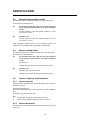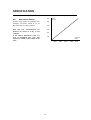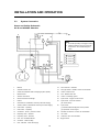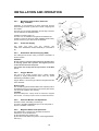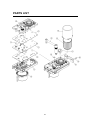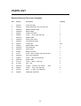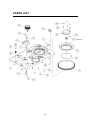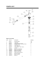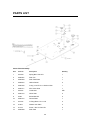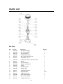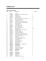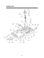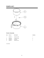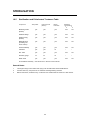
1
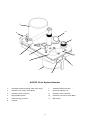
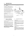
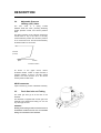
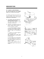
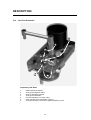
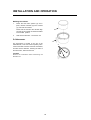
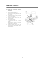
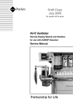
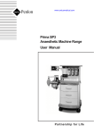
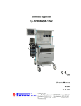
A200SP Circle Absorber
Service Manual
Partnership for Life
IMPORTANT
Servicing and Repairs
In order to ensure the full operational life of this
device, servicing by a Penlon-trained engineer
should be undertaken periodically.
We recommend that the absorber should be
serviced on the following schedule:
(a)
Six monthly inspection and function
testing.
(b)
Annual service which includes routine
replacement of seals etc, as preventive
maintenance.
(c)
Four-year
service
which
includes
additional component replacement.
Details of these operations are in this A200SP
Circle Absorber service manual. Servicing should
be carried out by Penlon trained engineers.
For any enquiry regarding the servicing or repair
of this device, contact the nearest accredited
Penlon agent:
or communicate directly with:
Technical Support Department
Penlon Limited
Abingdon
OX14 3PH
UK
Tel: 44 (0) 1235 547076
Fax: 44 (0) 1235 547062
E-mail: [email protected]
Always give as much of the following
information as possible:
1. Type of equipment
2. Product name
3. Serial number
4. Approximate date of purchase
5. Apparent fault
(i)
FOREWORD
This manual has been produced to provide
authorised personnel with information on the
function, routine, performance, servicing and
maintenance checks applicable to the A200SP
Absorber.
IMPORTANCE OF PATIENT MONITORING
WARNING
Anaesthesia systems have the capability to
deliver mixtures of gases and vapours to the
patient which could cause injury or death
unless controlled by a qualified anaesthetist.
Information contained in this manual is correct at
the date of publication. The policy of Penlon
Limited is one of continued improvement to their
products. Because of this policy Penlon Limited
reserves the right to make any changes which
may affect instructions in this manual, without
giving prior notice.
There can be considerable variation in the
effect of anaesthetic drugs on individual
patients so that the setting and observation of
control levels on the anaesthesia system does
not in itself ensure total patient safety.
Anaesthesia system monitors and patient
monitors are very desirable aids for the
anaesthetist but are not true clinical
monitors as the condition of the patient is also
dependent on his respiration and the
functioning of his cardio-vascular system.
Personnel must take themselves familiar with
the contents of this manual and the machine
function before using the apparatus.
IT IS ESSENTIAL THAT THESE ELEMENTS
ARE MONITORED FREQUENTLY AND
REGULARLY
AND
THAT
ANY
OBSERVATIONS ARE GIVEN PRECEDENCE
OVER MACHINE CONTROL PARAMETERS IN
JUDGING THE STATE OF A CLINICAL
PROCEDURE.
Copyright © Penlon Ltd. 2005
All rights reserved.
(ii)
CONTENTS
Page No.
USER RESPONSIBILITY
1
1.
WARNINGS AND CAUTIONS
2
2.
PURPOSE
4
3.
DESCRIPTION
3.1
Canisters
6
3.2
Inspiratory and Expiratory Non-return Valves (NRV)
6
3.3
Bag/Ventilator Switch
6
3.4
Adjustable Pressure Limiting (APL) Valve
7
3.5
Fresh Gas Inlet and Tubing
7
3.6
Manometer
8
3.7
Bypass Flow
8
3.8
End Tidal Carbon Dioxide Monitoring
8
3.9
Interface to AV-S Ventilator
9
3.10
Gas Flow Schematic
10
4.
SPECIFICATION
4.1
General Dimensions and Weight
4.2
Resistance of Breathing System
11
4.2.1
Expiratory Resistance
11
4.2.2
Inspiratory Resistance
11
4.3
Internal Compressible Volume
12
4.4
System Leakage Rate
12
4.5
Canister Capacity and Resistance
12
4.5.1
Canister Capacity
12
4.5.2
Canister Resistance
12
4.6
Non-return valves
13
5.
INSTALLATION AND OPERATION
5.1
Mounting the Absorber
14
5.2
System Connections
15
5.3
Changing CO2 Absorbent
17
11
6.
PRE-USE CHECKS
6.1
Pre-use Checklist
6.2
Leak Test
20
6.3
APL Valve Test and Pressure Relief Valve Test
20
6.4
Non-return Valve Test
21
6.5
Bag/Ventilator Switch Test
21
6.6
Leak Test - Canister Removed
22
19
(iii)
CONTENTS
Page No.
7.
SERVICE PROCEDURES
7.1
Service Frequency
23
7.2
Canisters and Seals
23
7.3
Condensate Drainage
24
7.4
Manometer
24
7.5
APL Valve
24
8.
SERVICE SCHEDULE
25
9.
PARTS LIST
29
Preventive Maintenance Parts Lists (12 months and 4 Years)
29
Major Assemblies
30
Bellows Plate and Top Cover
32
Bag Arm Assembly
34
Centre Plate Assembly
35
Manometer
36
10.
APL Valve
37
Base Plate Assembly
38
Canister Assembly
40
APPENDIX.
Sterilisation
10.1
Sterilisation Policy
41
10.2
Use of Bacterial Filters
41
10.3
Patient Circuit Components
41
10.4
Absorber Assembly - cleaning procedure before sterilisation
42
10.5
Sterilisation and Disinfectant Treatment Table
44
(iv)
USER RESPONSIBILITY
Statements in this manual preceded by the
following words are of special significance:-
This device has been built to conform with
the specification and operating procedures stated
in this manual and/or accompanying labels and
notices when checked, assembled, operated,
maintained and serviced in accordance with these
instructions.
To ensure the safety of this device it must be
checked and serviced to at least the minimum
standards laid out in this manual. A defective, or
suspected defective, product must not under any
circumstances be used.
The user must accept responsibility for any
malfunction which results from non-compliance
with the servicing requirements detailed in this
manual.
Additionally, the user must accept responsibility
for any malfunction which may result from misuse
of any kind, or non-compliance with other
requirements detailed in this manual.
WARNING
means there is a
possibility of injury to
yourself or others.
CAUTION
means there is a possibility of
damage to the apparatus or
other property
NOTE
indicates points of particular
interest for more efficient and
convenient operation.
The reader must take particular notice of the
warnings, cautions and notes provided throughout
this manual
Worn, broken, distorted, contaminated or missing
components must be replaced immediately.
Should such a repair become necessary it is
recommended that a request for service advice
be made to the nearest Penlon Service Centre.
This device and any of its constituent parts must
be repaired only in accordance with written
instructions issued by Penlon Limited and must
not be altered or modified in any way without the
written approval of Penlon Limited.
The user of this equipment shall have the sole
responsibility for any malfunction which results
from improper use, maintenance, repair, damage
or alteration by anyone other than Penlon or their
appointed agents.
USA and Canadian Federal Law restricts the sale
and use of this device to, or on the
order or, a licensed practitioner.
1
1.
WARNINGS AND CAUTIONS
The following WARNINGS and CAUTIONS must
be read and understood before servicing or
repairing this Anaesthetic Apparatus
7.
Do not connect a vacuum systems
must not directly to the APL valve. A
receiving system with positive and
negative pressure control functions
must be interposed. Systems must
comply with ISO 8835 Part 2. See 5.2.3.
8.
Underfilling of the canister can lead to
inefficient CO2 absorption.
Overfilling may result in poor sealing of
canister due to caking of granules and
abrasion of the canister and seal.
See 3.1 and 5.3.
9.
Do not use the Absorber without
ensuring
that
it
passes
all
pre-use checks. See Section 6.
10.
After
servicing
and
cleaning
procedures, verify positive action of the
bag/ventilator selector switch before
the unit is used clinically.
WARNINGS
General Information
1.
Personnel must make themselves
familiar with the contents of this
manual and the function of the A200SP
Absorber before servicing or use.
2.
Trichloroethylene must not be used in
association with soda lime.
3.
This unit is restricted to use with nonflammable anaesthetic agents only.
4.
The A200SP Circle System Absorber
must only be used when securely
mounted in an upright position.
a) The inspiratory and expiratory nonreturn valves (NRV) are gravity
operated.
b) Spillage
of
absorbent
may
contaminate the breathing system.
See 3.2/5.1
Check that at all times that the switch is
free to move from one end of its travel
to the other.
Using the absorber
11.
Before using the absorber
Condensation, which may collect in the
bottom of the absorber canister is
caustic and care must be taken not to
spill it on the skin when draining.
See section 7.3.
5.
6.
The
use
of
patient
Y-pieces
containing non-return valves in
connection with the Absorber is
hazardous, because two sets of nonreturn valves may easily be connected
in opposition, by error.
Breathing hoses and bags used with
the absorber must comply to ISO
5367 (Hoses) and ISO5362 (Breathing
Bags) respectively. The resistance
and compliance of these hoses and
bags provide essential factors for the
satisfactory use of this system.
13.
Kinking of the fresh gas tube is a
known cause of anaesthetic accident
and the use of unsuitable tubing can
contribute to this situation. See 3.5.
14.
Any breathing system utilising the
A200SP absorber must be fitted with:
a)
An oxygen monitor complying with
ISO7767.
b) A minute volume monitor.
c)
2
A breathing system integrity alarm.
WARNINGS AND CAUTIONS
CAUTIONS
1.
Do not sterilise
manometer.
(autoclave)
the
2.
Do not autoclave the electrical interface
unit at the rear of the absorber.
3.
Remove the absorbent canister before
autoclaving.
3.
If the absorber has to be lifted or
carried by hand, always support the weight
of the unit under the base. Do not lift
the absorber by gripping any of the
components attached to the top of the
absorber - the manometer, APL valve,
breathing circuit connectors, etc.
4.
Do not use any ventilator with the A200SP
absorber that does not comply with ISO
8835 part 2.
3
2.
PURPOSE
The A200SP Absorber is designed for use as part
of a closed breathing system for anaesthesia,
providing CO2 absorption in conjunction with the
appropriate ventilator, breathing hoses, reservoir
bags and patient connections.
Depending on the flow of fresh gas relative to
patient minute volume, the patient may receive
fresh gas or partial recirculated gas, as
determined by the anaesthetist.
The system incorporates a Bag/Ventilator switch
to enable:
a)
spontaneous breathing or manually
assisted ventilation in ‘Bag’ mode.
b)
use with an anaesthesia ventilator when
‘Ventilator’ is selected.
4
7
11
8
1
5
4
2
10
3
6
9
A200SP Circle System Absorber
1.
Adjustable pressure limiting valve (APL valve)
7.
Ventilator bellows housing
2.
Inspiratory non-return valve (NRV)
8.
Electrical interface unit
3.
Inspiratory hose connector
9.
Expiratory hose connector
4.
Bag/ventilator switch
10.
Expiratory non-return valve (NRV)
5.
Reservoir bag connector
11.
Manometer
6.
Canister
5
3.
DESCRIPTION
3.1
Canister
The canister (1) is designed to hold 1.3 kg of
loose absorbent, or to take a prepacked unit.
The maximum fill level is marked on the canister
and is equivalent to 1500 ml of absorbent.
DO NOT EXCEED MAXIMUM FILL LEVEL
Fill to a level within 12 mm (0.5 in) of this line.
In addition, the absorber must only be used when
securely mounted in an upright position – spillage
of absorbent may contaminate the breathing
system – see WARNING, in section 5.1.
3
The canisters seals at the top face.
The canister can be removed and refilled during a
clinical procedure.
2
The gas flow through the canister is from bottom
to top.
1
Note that the bag/ventilator connection is between
the absorber and the patient. Bag squeezing or
the use of mechanical ventilation does not result
in the transport of dust toward the patient, but
tends to drive dust back into the absorber.
3.2
Inspiratory and Expiratory
Non-return Valves (NRV)
3.3
Bag/Ventilator Switch (3)
Ventilator mode
In ‘Ventilator’ mode the reservoir bag is closed off
from the breathing system and the ventilator
connection port at the rear of the manifold block,
is in circuit.
The valves are positioned on the top of the
manifold block and control the direction of the gas
flow through the system.
Each valve consists of a rubber disc located over
a valve seat. The discs operate by gravity and are
retained by guides to prevent lateral movement.
WARNING The APL valve is out of circuit when
the system is in ‘Ventilator’ mode. The ventilator
must be equipped with a pressure relief valve.
The valves are visible through the top cover (2)
and the operation of each valve can be visually
checked as the patient breathes in and out.
Bag mode
The breathing bag acts as an additional overpressure protection device, preventing pressure
exceeding 60 cmH2O.
IT IS IMPORTANT THAT THE ABSORBER IS
MOUNTED UPRIGHT SO THAT THESE VALVES
MOVE IN A TRULY VERTICAL PLANE, WITH THE
VALVE SEATS HORIZONTAL.
WARNING
If no ventilator is connected to the absorber, care
must be taken to ensure that the bag/
ventilator switch is kept in the ‘Bag’ position, to
avoid gross loss of gas from the breathing
system and to maintain the reservoir bag in the
system.
6
DESCRIPTION
3.4
Adjustable Pressure
Limiting (APL) Valve
The APL valve is a spring loaded
stainless steel disc valve, providing breathing
system pressure control, and excess pressure
relief.
The spring pressure can be varied by rotating the
control knob on top of the valve. In the fully
counterclockwise position the minimum pressure
is 1.0 cmH2O at 6 L/min. This can be increased by
clockwise rotation to 60 cmH2O.
60
Pressure
(cmH2O)
Open
Closed
Clockwise rotation
As shown in the graph above, further
clockwise rotation causes a rapid increase in
opening pressure so that in the fully closed
position, the valve functions as a 60 cmH2O
excess pressure relief valve.
AGSS connector
Taper connector (1) at rear of absorber assembly.
3.5
Fresh Gas Inlet and Tubing
The fresh gas inlet (2) is at the rear of the
absorber.
The absorber is supplied with a fresh gas hose
assembly with attached end fitting. Do not use
any other type of hose
1
WARNING
Kinking of the fresh gas tube is a known cause of
anaesthetic accident and the use of unsuitable
tubing can contribute to this situation.
2
7
DESCRIPTION
3.6
NOTE:
Manometer
The use of a manometer is strongly
recommended at all times.
The manometer is located on the top of the
manifold block to the rear of the expiratory valve .
Manometer scale:
–10 to +100 cmH2O
Manometer accuracy:
±5%
(within range
+10 to 80 cmH2O)
CAUTION
Remove the manometer before autoclaving the
absorber unit.
3.7
Bypass System
It
is
strongly
recommended
that
a
capnometer is used to prevent the risk of
hypercapnia.
When the canister is removed, expiratory gas
passes directly to the APL valve and bag, or
ventilator, without passing through the absorbent.
This allows the canister to be refilled during a
clinical procedure
3.8
End Tidal Carbon Dioxide
Monitoring
The use of end tidal carbon dioxide monitoring
is strongly recommended.
Connection of a suitable analyser must be made
between the patient’s airway and the patient
connection Y-piece.
Detailed instructions are provided by the
manufacturers of the analyser.
8
DESCRIPTION
3.9
Interface to AV-S Ventilator
The absorber is designed to interface with
the AV-S Ventilator and the ventilator
bellows unit (1) is built into the absorber..
1
The interface cable links the connector (2)
on the ventilator control panel to the
multifunction connector (3) on the interface
unit at the rear of the absorber.
a)
The A200SP is fitted with fitted with a
sensor that detects the position of the
absorber bag/vent control (4).
The sensor signal cabling is routed
internally to connector (3)
b)
Operation of the Bag/Vent control will
trigger automatic Mode switching on
the AV-S ventilator, as follows:
4
2
i) If the Absorber Bag/Vent control is
moved from Vent to Bag, the ventilator
will change from Volume Mode, or
Pressure Mode, into Spontaneous
Mode.
ii) Switching the absorber Bag/Vent
control from Bag to Vent:
The ventilator will reset from
Spontaneous Mode to the previously
set active mode.
iii) If the ventilator is in any mode other
than those detailed above, operation of
the absorber Bag/Vent control will not
affect the ventilator.
NOTE
This
function
can
be
enabled/disabled through the AV-S onscreen menus (refer to the AV-S user
manual).
3
9
DESCRIPTION
3.10
Gas Flow Schematic
6
1
2
3
6
5
7
4
Inspiratory Gas Path
1.
2.
3.
4.
5.
6.
7.
Patient Gas from bellows
Through the bag/vent switch
Down to absorbent canister
Through the absorbent
Into the inspiratory non-return valve
Fresh gas flow from anaesthetic machine
Through inspiratory connector to patient breathing circuit
10
4.
SPECIFICATION
NOTE
Information in this section complies with the requirements of ISO 8835–2.
4.1
General Dimensions
All figures are approximate
Overall height
380 mm
Width
186 mm
Depth
240 mm
Weight (empty)
5.7 kg
Mounting system
Polemount assembly
4.2
Resistance of Breathing System
Resistances listed in 4.2.1 and 4.2.2 are measured with:
(A)
An absorber fitted with 1060 mm (42 inch) breathing
hoses complying with ISO 5367, and a Penlon Safelock
Y-piece.
(B)
Absorber only.
The canister must be filled to the MAX level with fresh absorbent, and theAPL
valve fully open.
Bacterial Filter:
A bacterial filter must be used in the patient breathing system to protect the
oxygen sensor.
Use an appropriate filter that does not raise the resistance values of the whole
system to above 0.6 kPa (6 cmH2O).
4.2.1
Expiratory Resistance
Tested with a flow of 6 L/min of air through the fresh gas inlet and an induced
flow of 60 L/min through the breathing system.
(A)
expiratory resistance: less than 0.6 kPa (6 cmH2O)
(B)
expiratory resistance: less than 0.5 kPa (5 cmH2O)
4.2.2
Inspiratory Resistance
Tested with a flow of 6 L/min of air through the fresh gas inlet
and an induced flow of 60 L/min through the breathing system.
(A)
inspiratory resistance: less than 0.6 kPa (6 cmH2O)
(B)
inspiratory resistance: less than 0.45 kPa (4.5 cmH2O)
11
SPECIFICATION
4.3
Internal Compressible Volume
Note that the reservoir bag is not fitted and the bag mount blocked.
These figures are measured with:
(A)
An absorber fitted with 1060 mm (42 inch) breathing
hoses complying with ISO 5367, and a Penlon Safelock
Y-piece.
Volume required to raise the system pressure to 3 kPa
(30 cmH2O) = 180 ml
(B)
Absorber only.
Volume required to raise the system pressure to 3 kPa
(30 cmH2O) = 170 ml
Other disposable breathing hoses may give different figures; the
supplier of the hose will provide compressible volume figures.
4.4
System Leakage Rate
The patient connection port is sealed and the APL valve fully closed.
These figures are measured with:
(A)
An absorber fitted with 1060 mm (42 inch) breathing
hoses complying with ISO 5367, and a Penlon Safelock
Y-piece.
Absorber ‘ON’
Leakage rate: less than 50 ml/min at 3 kPa (30 cmH2O)
(B)
Absorber only.
Absorber ‘OFF’, canister removed.
Leakage rate: less than 50 ml/min at 3 kPa (30 cmH2O)
4.5
Canister Capacity and Resistance
4.5.1
Canister Capacity
When filled to the MAX level mark, the canister holds 1.3 kg (2.87 lb) of
absorbent (1500 ml).
Recommended absorbent:
Soda lime or barium lime, with a colour indicator, 4-8 mesh, supplied in
bulk.
Alternatively, pre-packs may be used.
Note
i)
ii)
4.5.2
The absorber canister is not electrically conductive.
Cleaning and sterilisation details are given in section 7.
Canister Resistance
The resistance of a freshly filled canister is less than 0.2 kPa (2 cmH2O)
at 60 L/min.
12
SPECIFICATION
4.6
60
Non-return Valves
Pressure drop across the inspiratory and
expiratory non-return valves at an air
flow of 60 L/min: 0.1 kPa (1 cmH2O).
50
Note that flow characteristics are
identical for valves in a dry or wet
condition.
30
Flow
(L/min)
40
20
A ‘wet’ valve is defined as a valve in a
flow of humidified gas, such that
moisture is visible on the surface of the
valve.
10
Pressure
(kPa)
0.02
13
0.04
0.06
0.08
0.01
5.
INSTALLATION AND OPERATION
2
3
1
5.1
Mounting the Absorber
CAUTION
If the absorber has to be lifted or carried by hand,
always support the weight of the unit under the base.
Do not lift the absorber by gripping any of the
components attached to the manifold block at the top
of the absorber.
WARNING
The absorber assembly must only be used when
securely mounted in an upright position.
a) Non-return valves are gravity operated
b) Spillage of absorbent may contaminate the
breathing system.
Polemount bracket assembly (1)
Secure the polemount assembly to the side of the
anaesthetic machine.
Mount the absorber on the bracket assembly, and
secure by tightening the knob (2)
Height Adjustment
Slacken the knob (2) and position the assembly at
the required height.
Tighten the knob.
Lateral Adjustment
Slacken the knob (3) and carefully adjust to the
required position.
Tighten the knob.
14
INSTALLATION AND OPERATION
5.2
System Connection
Hoses and Cables Schematic
AV-S and A200SP Absorber
25
3
26
23
24
2
20
19
Note
18
1. AV-S has spirometry and oxygen monitor.
2. Interface cabling is shown for Prima SP
On/Off switch and A200SP Bag/Vent
switch.
12
1
4
11
10
21
16 27
14
29
26
13
28
15
5
17
22
12
6
9
7
8
1.
Bellows
18.
Drive Gas Inlet - Ventilator
2.
Ventilator Control Unit
19.
Drive gas Outlet - ventilator control unit to bellows
3.
Outlets to Anaesthetic Gas Scavenging System (AGSS)
20.
Outlet - Exhaust Valve
4.
Bacterial Filter
21.
Inlet - Bellows Drive Gas
5.
Absorber valve block
22.
Outlet - to breathing system
6.
Heat and moisture exchanger
23.
Input socket - Oxygen monitor sensor
7.
Patient
24.
Input socket - Prima SP interface
8.
CGO Block on anaesthetic machine (Fresh Gas Supply)
9.
Auxiliary Outlet on anaesthetic machine (Drive Gas Supply)
25.
Input socket:
10.
Flow sensor - expiratory
(i) A200SP Absorber Bag/Vent control position
11.
Flow sensor - inspiratory
(ii) Spirometer sensor signal
12
Connectors - sensor - pressure monitor
26.
Interface connections on Prima SP and A200SP
13.
Expiratory Valve - Absorber
27.
APL Valve
14.
Inspiratory Valve - Absorber
28
15.
Inlet - from Ventilator Bellows
29
16.
Connector - Reservoir Bag
17.
Inlet - Absorber - Fresh Gas Supply
15
(SP on/off switch)
Outlet from APL Valve to AGSS
Oxygen sensor
INSTALLATION AND OPERATION
5.2.1
Breathing System Hose, Reservoir
Bag, Ventilator
3
Inspiratory (1) and expiratory (2) hose connectors and the
reservoir bag connector (C) are 22 mm male, complying with
ISO 5356/1.
10
The bag arm (3) is height adjustable, and the bag connector
can be rotated to the desired position
Ventilator connection point (4)
Connect a 16 mm diameter corrugated hose between the
ventilator control unit drive gas outlet (labelled: DRIVE GAS)
and the connector (4) at the rear of the absorber.
5.2.2
Fresh Gas Supply
7
The fresh gas hose from the common gas
outlet of the anaesthetic machine.assembly is connected at
(5).
5.2.3
2
1
8
Anaesthetic Gas Scavenging (AGS)
The outlet (6) from the APL valve (7) must be connected to a
receiver system.
WARNING
Do not connect a vacuum system directly to the APL valve.
A receiving system with a positive and negative pressure
control function must be interposed.
The system must comply with the requirements of ISO 8835
part 2.
5.2.4
Oxygen Monitor
The use of an oxygen monitor (and a carbon dioxide
analyser) is highly recommended when using any partial
rebreathing anaesthetic system.
Oxygen Monitor - the sensor (8) is fitted to the right hand side
of the absorber.
Bacterial Filter
Use a breathing system bacterial filter in the expiratory limb of
the breathing circuit to protect the oxygen sensor (see section
5 in the AV-S ventilator user manual).
CAUTION
Replacement/Disposal - always follow the instructions supplied
with the filter, and always replace at the recommended interval.
5.2.5
Pressure Monitor and Spirometer
Pressure monitor self-sealing connector (9).
Connect to PATIENT PRESSURE port on the rear panel of
the AV-S ventilator control unit.
5.2.6
Bag/Vent Switch and Spirometer
The multifunction connector (10) provides an interface
between the AV-S ventilator and
(a) the spirometer flow sensors, and
(b) the sensor that detects the position of the Bag/Ventilator
switch (11) .
16
10
6
4
5
9
INSTALLATION AND OPERATION
5.3
Changing CO2 Absorbent
WARNING
If the absorbent is to be changed during clinical use, adequate
fresh gas flow must be maintained to prevent excessive build
up of CO2.
2
Removing the canister
WARNING
Condensation, which may collect in the bottom of the
absorber canister, is caustic. Avoid skin contact when
draining.
1.
2.
Grip the handle (1), turn the canister anti-clockwise, and
remove carefully.
Check the level of liquid in the canister.
Carefully lift out the inner absorbent container (2).
WARNING
Condensate may drip from the container.
Use a cloth to prevent spillage.
3.
Dilute the liquid in the canister with water before disposal.
Follow your hospital procedure.
4.
Dispose of the absorbent from the inner container.
Cleaning
Soda lime tends to adhere strongly to surfaces when it has
become exhausted.
To maintain good sealing, the canister, absorbent container,
seal, and the sealing plate above the canister should be wiped
with a damp cloth to remove particles of soda lime, whenever
the absorbent is changed.
Refilling with absorbent
WARNING
Underfilling can lead to inefficient CO2 absorbtion. Overfilling
may result in poor sealing of the canister due to caking of
granules and abrasion of the canister seal.
1.
Pre-packed soda lime:
Remove the packing seal, following the manufacturer’s
instructions.
(a)
Check that the container (2) is clean and dry and empty
of dust or soda lime granules
(b)
Insert the pre-pack into the container. Follow the
instructions provided by the pre-pack manufacturer.
2.
Using bulk packed soda lime, check the container in the
same manner, then place it on a horizontal surface and fill
it with soda lime up to the MAX line, but not above it.
17
1
3
INSTALLATION AND OPERATION
Refitting the canister
1.
Check that the three spacers (3) are in
place, refit the container (2) to the canister
(1), then refit the canister.
2
Check that the seal and the canister align
correctly as the canister is rotated clockwise
to the locked position.
2.
Leak test the absorber – see section 6.2.
5.4 Manometer
1
The manometer is located on the top of the
manifold block, to the rear of the inspiratory valve.
If the manometer has been removed and refitted,
Function test the absorber, checking for leaks at
the manometer, before clinical use.
3
CAUTION
Remove the manometer before autoclaving the
absorber unit.
18
6.
PRE-USE CHECKS
6.1
Pre-use Checklist
1.
Check the absorbent, replace if necessary.
Before refitting the canister, check that the
sealing surfaces are clean and dust free.
Ensure that the canister in place when
refitted.
2.
Check that the fresh gas hose is connected
to the anaesthetic machine.
Note that the anaesthetic machine must be
leak tested before the absorber pre-use
checks are made.
3.
Leak test the absorber – see section 6.2
4.
Carry out a function check and
pressure relief test on the APL valve –
see section 6.3.
5.
Check the inspiratory and expiratory nonreturn valves for correct operation – see
section 6.4.
6.
Check the Bag/Ventilator switch for correct
operation – see section 6.5.
7.
Carry out a leak test with the canister
removed - see 6.6
8.
Repeat the absorber leak test – see section
6.2.
19
PRE-USE CHECKS
The procedures detailed in sections 6.2 to
6.6 must be carried out in the order listed.
The absorber must be attached to an
anaesthetic machine, which must be leak tested
before the checks are carried out.
Check that the manometer is zeroed before use.
6.2
Leak Test
Check that the bag is correctly fitted, and set the switch
(1) to ‘Bag’.
Connect the fresh gas hose to the anaesthetic
machine.
Use a breathing system hose to connect the patient
ports (2) to form a closed, leak-free circuit.
4
1
Close the APL valve (3).
1.
Turn on a flow of 2 L/min of oxygen and
pressurise the system.
2.
Stop the gas flow when the system pressure
reaches 3 kPa (30 cmH2O) and check that
pressure is maintained, i.e. the pressure must
not fall to zero in less than one minute.
6.3
APL Valve Test and
Pressure Relief Test
APL Valve Function
1.
Open the APL valve (3).
Check that gas escapes freely from the system
through the valve outlet.
APL Valve Flow Resistance
2.
Set maximum flow and check that the retained
pressure is less than 0.5 kPa (5 cmH2O).
3.
Reduce flow to minimum.
Pressure Relief
4.
Close the APL valve fully (clockwise).
5.
Remove the reservoir bag and block the bag
port (4).
Use the flow controls on the anaesthesia
machine to produce a high flow of gas into the
system and check that the APL valve provides
excess pressure relief.
The manometer reading must not exceed 6 kPa
(60 cmH2O) ± 10% at 6 L/min.
Refit the reservoir bag.
20
3
2
PRE-USE CHECKS
6.4
Inspiratory and Expiratory
Non-return Valve Test
1.
Detach the hose connecting the inspiratory
(1) and expiratory (2) connectors.
2.
Check that the APL valve (3) is closed.
3.
Block the inspiratory valve outlet (1) with a
suitable bung, and inflate the reservoir bag
with a 2 L/min oxygen flow.
4.
Turn off the gas flow and check that the bag
does not empty by reverse flow through the
expiratory valve (2).
5.
Remove the bung and attach a spare
reservoir bag to the inspiratory valve
connector (1).
6.
Turn on a 2 L/min oxygen flow and fully
inflate this bag (and the absorber reservoir
bag).
7.
Turn off the gas flow. Check that gas cannot
be forced through the inspiratory valve by
gentle squeezing of the spare bag on the
valve outlet.
8.
Remove the bag from the inspiratory
connector (1).
6.5
1.
Bag/Ventilator Switch
Refit
the
breathing
hose
between
the
inspiratory (1) and expiratory (2) connectors.
2
Set a flow of 10 L/min and check that bellows
starts to inflate.
Ensure that bag is not inflating.
3.
Move switch (4) to Bag position and watch
bag inflate and bellows stops rising.
When the pressure reads 3 kPa (30 cmH2O)
turn off the flow of gas.
4.
Select ventilator, pressure on gauge should
drop, but bag should remain inflated.
5.
Squeeze bag, there should be no loss of
pressure, and bellows must not rise.
21
4
2
3
1
PRE-USE CHECKS
6.6 Leak test - Absorber Canister
Removed
1.
Remove absorbent canister (1).
Set the switch (2) to Bag position and close
APL valve(3).
2.
Pressurise the system to 3 kPa (30 cmH2O)
and turn off the gas flow.
3.
Check that pressure does not fall to zero
within one minute.
4.
Refit absorbent canister.
2
A pressure loss will occur as valves
operate.
3
Repressurise the system to 3 kPa (30
cmH2O) and turn off gas flow.
5.
1
Check that pressure does not fall to zero
within one minute, then open APL valve to
release pressure.
22
7.
SERVICE PROCEDURES
7.1
Service Frequency
Servicing and repairs must only be carried
out by Penlon-trained technicians and
engineers.
(a)
Six-monthly inspection and function
testing.
(b)
Annual and four-year service which
includes routine replacement of seals etc.,
as preventive maintenance.
7.2
Canister and Seals
Cleanliness is the essential requirement for all
components in contact with absorbent.
Soda lime tends to adhere strongly to surfaces
when it has become exhausted.
To maintain good sealing, the canister,
absorbent container, seal, and the sealing plate
above the canister should be wiped with a damp
cloth to remove particles of soda lime, whenever
the absorbent is changed.
These components should be scrubbed under
running water when the complete system is
dismantled for sterilisation or disinfection.
See section 8.4.
23
SERVICE PROCEDURES
7.3
Condensate Drainage
WARNING
Condensation, which may collect in the bottom
of the absorber canister is caustic and care must
be taken not to spill it on the skin when draining.
Wear suitable protective gloves.
Dilute the liquid with water before disposal.
2
Daily Procedure:
1.
Check the level of liquid in the canister (1).
If necessary, remove the canister by
turning anti-clockwise, and carefully lift out
the inner absorbent container (2).
WARNING
Condensate may drip from the container.
Use a cloth to prevent spillage.
2.
Dilute the liquid in the canister with water
before disposal. Follow your hospital
procedure.
3.
Refit the container, ensuring that the three
spacers (3) are located as illustrated.
4.
Refit the canister to the absorber.
7.4
1
3
Manometer
Remove the manometer before sterilisation or
disinfection.
Grip the manometer and detach from the
absorber.
CAUTION
7.5
Do not sterilise the manometer.
APL Valve
Autoclave the valve as part of the absorber
assembly - - see section 8.5. .
Check that the valve is in the open position before
autoclaving.
Do
NOT
wash
in
cleaning/washing machine.
an
automatic
24
8.
1
1.1
1.2
1.3
1.4
SERVICE SCHEDULE
Initial Checks
Check serial numbers to determine service required.
Check general condition of Absorber and fittings.
Quarter turn absorbent canister and remove.
Remove inner canister.
Drain any condensate from outer canister and re-fit:
Caution Caustic Solution
If component replacement is required, disconnect fittings at rear of absorber and
remove absorber from anaesthesia machine.
Place absorber on flat work surface with absorbent canister removed
2
2.1
2.2
Bag arm assembly
Check bag arm assembly for movement and security of attachment
Unscrew Bag arm connector and replace O' Ring - 041217
3
3.1
Manometer
Grip manometer assembly and remove by pulling firmly upwards.
Remove manometer and ensure it indicates zero. If not adjust using small screw.
Using a hand-bulb and test manometer apply increasing pressure, up to 100 cmH2O
and ensure manometer reads within +/- 5 cmH2O.
Replace manometer O-ring - 5000349
3.2
3.3
4
4.1
4.2
4.3
5
Bellows assembly
Remove bellows canister.
Examine bellows, diaphragm and canister seal for cleanliness and deterioration
Replace canister seal - 5000072
Replace bellows and diaphragm valve as part of ventilator service procedure
Electrical Interface Box
Disconnect electrical interface connector.
Undo the four thumbscrews securing electrical box to absorber and remove electrical
box
Replace four O-rings - 041230
6
Internal component inspection and replacement (Upper)
Undo the eight ¼ turn Dzus fasteners and lift up Bellows Plate
Replace Bellows Plate gasket - 5000080
Replace Inspiratory and Expiratory Disc valves (x2) - 5000394
7
APL Valve
Unscrew APL valve retaining sleeve.
Remove valve plunger and replace APL valve seal - 5000364.
Re-fit plunger and retaining sleeve
8
Internal component inspection and replacement (Lower)
Lift away the Centre Plate
Replace the Base Plate gasket - 5000081
Replace the Bag/Ventilator switch o-rings (x2)- 5000202
Inspect by-pass valve seals for cleanliness and deterioration
Clean seals and re-grease valve stems
Replace absorbent canister gasket - 5000092
9
By-pass plate removal
Remove the 'E' clips securing the valve seals and supports and remove.
Remove further two 'E' clips from by-pass plate guides.
25
SERVICE SCHEDULE
Lift Bellows Plate from the By-pass Plate
Replace large o-ring - 5000273, and small o-ring - 5000274
Replace valve seals (x3) - 5000097
Replace seal support internal o-rings (x3) - 5000135
Apply oxygen-safe grease to By-pass Plate guides.
Re-assemble
10
Re-assembly
Re-fit Base Plate gasket; Centre Plate; Bellows Plate gasket
When re-fitting Bellows Plate ensure Bag/Ventilator knob is aligned with quadrant
shaft and switch 'Push-Pin' is engaged.
Secure Bellows Plate with eight Dzus fasteners
Re-fit Bag arm connector and tighten. Use small drop of Loctite 243
Re-fit manometer ensuring it securely snaps into place
Re-fit electrical box and connect interface cable
Re-fit bellows assembly and absorbent canister assembly
11
11.1
Set Up
Connect absorber to anaesthetic machine that has been checked for LEAKS.
Check that manometer reads zero.
12
12.1
12.2
12.3
12.4
12.5
12.6
Leak Test
Absorber canister fitted
Ensure bag fitted to bag port and Bag/Vent switch to 'Bag' position.
Connect patient ports with hose to form a closed circuit.
Close APL valve.
Set a flow of 2 l/min on the anaesthesia machine.
Stop the gas flow when Manometer reads 3 kPa (30 cm H2O).
Ensure pressure does not fall to zero within one minute.
13
13.1
13.2
APL Valve Test And Pressure Relief Test
Fully open APL valve
Set maximum flow rate.
Check that manometer indicates 5cm H2O or less.
13.3
Turn off gas supply
13.4
Close the APL valve Fully.
13.5
Use O2 flow and check APL valve relieves pressure at 6 kPa (60cm H2O) +/- 10 %
at, 6-l/min flow rate.
14
14.1
14.2
14.3
14.4
14.5
14.6
14.7
Inspiratory and Expiratory Non-return Valve Test
Remove hose from patient ports.
Occlude Inspiratory port with suitable bung.
Fully close APL valve
Fit re-breathing bag to bag arm and inflate with O2 flush.
Ensure bag does not deflate within one minute.
Remove bung from inspiratory port.
Transfer re-breathing bag, from bag-arm to Inspiratory port.
Occlude bag-arm with suitable bung.
Inflate bag with 02 flush.
Remove occlusion from bag port.
Ensure rebreathing bag fitted to inspiratory port does not deflate within one minute.
Remove bag from inspiratory port
Refit bag to bag-arm.
26
SERVICE SCHEDULE
15
15.1
15.2
15.3
15.4
Bag / Ventilator Switch Test 2
Ensure ventilator bellows and bag-arm bag are deflated
Refit hose to patient ports.
Select bag/vent switch to 'vent' and ensure APL valve fully closed.
Set a flow of 10 l/min and check that bellows starts to inflate.
Ensure that bag is not inflating.
Move Bag/Vent switch to Bag position.
Observe bag inflate and bellows stops rising.
When the pressure reads 3 kPa (30 cm H2O) turn off the flow of gas.
Select ventilator.
Pressure on gauge should drop but bag should remain inflated.
Squeeze bag.
There should be no loss of pressure and bellows must not rise.
16
16.1
Absorber Bypass function
Remove absorbent canister.
Select Bag position and close APL valve
Pressurise the system to 3 kPa (30cm H2O).
Turn off gas flow.
Check that pressure does not fall to zero within one minute.
Re-fit absorbent canister.
A pressure loss will occur as valves operate.
Re-pressurise the system to 3 kPa (30 cmH2O).
Turn off gas flow.
Check that pressure does not fall to zero within one minute.
Open APL valve to release pressure.
16.2
16.3
16.4
16.5
17
17.1
17.2
17.3
17.4
17.5
17.6
Paperwork
Restore user settings.
Sign and date service card, indicate service 6, 12, or 60 month.
Attach service cards to equipment.
Remove all tools, test equipment
THINK, carry out visual checks.
Fill out service report.
NOTE
This checklist is prepared for use by Penlon-trained Service Engineers.
Other components may be replaced at the discretion of the Engineer if signs of wear
are apparent.
If a replacement is necessary, inform the appropriate hospital engineer.
,
27
SERVICE SCHEDULE
28
9.
PARTS LIST
A200SP Preventive Maintenance Kits
Annual Service Components
Manometer O-ring
Bag arm connector O-ring
Electrical Box O-ring (x4)
Disc valves (x2)
Bellows Plate gasket
Base Plate gasket
Canister gasket
Bag vent switch O-ring (x2)
Fresh gas hose (0.5 metres)
Tie wrap (x2)
Bellows Canister seal
5000349
041217
041230
5000394
5000080
5000081
5000092
5000202
462631
103612
5000072
4-year Service Components
Manometer O-ring
5000349
Bag arm connector O-ring
041217
Electrical Box O-ring (x4)
041230
Disk valves (x2)
5000394
Bellows Plate gasket
5000080
Base Plate gasket
5000081
Canister gasket
5000092
Bag vent switch O-ring (x2)
5000202
Fresh gas hose (0.5 metres)
462631
Tie wrap (x2)
103612
Bellows Canister seal
5000072
APL valve seal
5000364
By-pass seal (x3)
5000097
Seal support internal O-ring (x3)
5000135
Large canister plate O-ring
5000273
Small canister plate O-ring
5000274
29
PARTS LIST
Major Assemblies and Miscellaneous Components
Item
Part No.
Description
Quantity
1
5000122
Base Plate Assembly
1
2
5000119
Centre Plate Assembly
1
3
5000118
Bellows Plate Assembly
1
4
5000120
Canister Assembly
1
5
5000121
Pressure Gauge Assembly
1
7
300049
Canister Screen Printed
1
9
5000117
Bag Arm Assembly
1
10
5000394
Valve Disc
2
11
5000080
Bellows Plate Gasket
1
12
5000081
Base Plate Gasket
1
13
5000320
Electrical Box Assembly
1
14
019075
Screw M3 X 30 Cap HD
4
15
011108
Cap (M3)
4
16
5000389
APL Valve Label
1
17
406027
Adult Bellows Assembly
1
NOTE
Components contained in assemblies 1 to 5, and 9 are shown in subsequent pages in this
section
30
PARTS LIST
31
PARTS LIST
Bellows Plate and Top Cover Assembly
Item
Part No.
Description
Quantity
1
054529
Valve-One Way
1
2
5000071
Dowel Pin Ø6.0 X 20.0 Long ST STL
1
3
5000072
Bellows Canister Seal
1
4
5000495
Bellows Ring
1
5
025606
Washer M3 Fibre
4
6
020808
Screw
4
7
5000116
Bellows Plate
1
8
5000393
Switch Knob Label
1
9
5000491
Compression Spring
9
10*
057003
Loctite 242
A/R
11
406059
Bellows Base - Seat
1
12
5000304
Stud Assembly
9
13
5000076
Switch Knob
1
14
406037
Bellows Location
4
15
01130
Screw M5 X 16 SKT Cap Head ST STL
1
16
5000123
APL Valve Assembly
1
17
019003
Screw
2
18
5000109
Switch Shaft
1
19
019110
Screw
3
20
011108
Cap
21
5000137
O Ring
94.0 I/D X 1.5 section
22
020807
Screw
No4 X 3/8" Self Tap
8
23
041204
Seal
5.1 I/D X 1.6 CSØ Viton
1
24
406020
Diaphragm Assembly
No 6 X 3/8" Self Tap
M3 X 20 Ss SK HD
M3 X 14 Cap HD
M3
3
Viton
1
1
32
PARTS LIST
33
PARTS LIST
Bag Arm Assembly
Item
Part No.
Description
Quantity
1
2
3
4
5
6
7
8
9
10
11
12
13
14
15
16
029011
057003
041231
5000131
041207
5000391
041212
041217
5000085
5000086
5000087
5000084
5000127
5000077
5000078
5000079
Molykote BG87
Loctite 242
O' Ring Ø 20.0 X 1.5 Cs
O Ring 17.0 I/D X 1.5 Section Viton
O' Ring 0251-16
Label - Bag Arm
'O' Ring Ø19.1 X Ø1.6 Viton
O' Ring
Bag Arm Locking Ring
Bag Arm Locking Nut
Bag Arm Connector
Bag Arm Tube Inner
Screw M4 X 8 SKT Set
Bag End Adaptor
Bag Arm Swivel
Bag Arm
A/R
A/R
3
1
1
2
1
1
1
1
1
1
3
1
1
1
34
PARTS LIST
Centre Plate Assembly
Item
Part No.
Description
Quantity
1
031064
Spring Ø4.6 X 8.0LG
1
2
5000307
Push Pin
1
3
5000309
Push Rod Plate
1
4
5000075
Hollow Dowel
2
5
5000126
O-ring 14.0 I/D X 1.5 Section Viton
1
6
5000111
APL Valve Seat
1
7
057001
Loctite 601
A/R
8
5000115
Valve Seat
2
9
0462
Ø3/16 Ball SS
2
10
5000112
Centre Plate
1
11
041231
O' Ring Ø 20.0 X 1.5 CS
2
12
01067
Washer M3 Plain
2
13
01153
Screw M3 X 6 Pan HD
2
14
5000308
Push Rod
1
35
PARTS LIST
Manometer
Item
Part No.
5000121
Description
Quantity
Manometer Assembly
1
Includes:
1
5000349
‘O’ Ring 10.0 I/D X 1.5 Section Viton
1
2
5000083
Gauge Connector
1
3
5000082
Gauge Cover
1
36
PARTS LIST
APL Valve
Item
Part No.
Description
Quantity
1
2
3
4
5
6
7
8
9
10
11
12*
13
14
15*
16
17
18
5000105
5000106
5000107
5000125
019074
041245
5000128
020001
5000110
5000108
041256
5000363
5000364
020510
029011
020533
5000468
019117
APL Valve Plunger
APL Valve Adjuster
APL Valve Body
Compression Spring
M5 X 16 LG Set Screw Ss
O Seal Ø7.0 X 1.5
O Ring 24.0 I/D X 2.0 Section Silicon
M5 Nut
APL Valve Knob
Spring Location Bush
O Ring
Retaining Sleeve
Plunger Seal
Dowel Pin Ø3 X 20
Molykote BG87
Dowel Pin Ø3 X 8
Knob Location Plate
M3 X 6LG CSK HD
1
1
1
1
1
1
1
1
1
1
1
1
1
2
A/R
1
1
3
19
041238
O’ Ring Ø 23.0 X 1.5
1
37
PARTS LIST
Base Plate Assembly
Item
Part No.
Description
Quantity
1
2
3
4
5
6
7
8
9
10
11
12
13
14
15
16
17
18
041222
5000273
5000442
5000306
01059
5000202
01013
5000136
5000143
5000274
01011
041239
5000345
5000346
019087
029011
5000344
5000342
O’ Ring
O Ring 59.5 I/D X 3.0 Section Silicon
Spring Clip
Location Dowel
M2.5 X 6 Ch HD
O Ring 18.0 I/D X 2.0 Section Silicon
M4 X 10 SKT HD Cap
Compression Spring
O Ring 5.0 I/D X 1.5 Section Viton
O Ring 24.5 I/D X 3.0 Section Silicon
M4 Plain Washer
O Ring Ø21 X 1.5
Cell Location Spigot
Cell Location Plate
M3 X 16 Cap HD Screw
Molykote BG87
O Ring 8.0 I/D X 2.0 Section Viton
Extension Spring
1
1
9
9
18
2
1
1
1
1
1
1
1
1
2
A/R
1
1
19
20
21
22
23
24
25
26
27
28
29
30
31
32
33
34
35
36
37
38
39
5000358
5000490
5000343
5000129
019067
5000104
020420
5000103
5000102
5000134
5000101
5000100
5000135
5000099
5000098
5000096
5000093
5000094
102714
5000095
041256
Canister Location Pin
Spring Locating Spacer
O Ring 16.0 I/D X 2.0 Section Viton
O Ring 18.0 I/D X 2.0 Section Viton
M4 X 12 SKT HD Cap
Valve Stem
Circlip External Ø8mm Shaft
Seal Support Plate
22 mm Taper
Compression Spring
Switch Quadrant
Base Plate
O Ring 8.0 I/D X 1.5 Section Viton
Bypass Plate
Quadrant Shaft
17 mm Taper
Spring Location Spigot
Fresh Gas Connector
O2 Fuelcell
Orifice Plate
O Ring
8
2
1
3
4
2
6
3
2
2
1
1
3
1
1
1
1
1
1
2
1
40
41
42
43
44
5000388
5000097
5000092
5000089
031046
19 mm Taper
Valve Seal
Canister Seal
Support Pin
Spring 16.76 O/D X 16 LG
1
3
1
2
2
38
PARTS LIST
39
PARTS LIST
Canister Assembly
Item
Part No.
Description
Quantity
1
5000074
Canister Outer
1
2
5000396
Location Tube
3
3*
Sodalime
Pre-Pack
1
4
5000073
Canister Inner
1
*not shown
40
10. APPENDIX
10.1
Sterilisation Policy
Follow your local hospital guidelines. Autoclavable
components are listed in section 8.5.
10.2
Bacterial Filters
The use of respiratory bacterial filters is essential
to protect the oxygen sensor mounted at the side of
the side of the absorber.
Fit a bacterial filter to the expiratory limb of the
breathing circuit.
In addition a heat and moisture exchange (HME) unit
should be fitted at the patient Y-piece.
Refer to the diagram in section 5 – ‘Breathing Circuit
Connections’, and the information on flow resistance in
sections 4.2.1, and 4.2.2.
Filters may be sterilisable or single use. Please read
the labelling supplied by the manufacturer.
CAUTION
Replacement/Disposal - always follow the instructions
supplied with the filter or HME.
Always renew components at the recommended interval
NOTE
If a bacterial filter has not been used in the expiratory limb
of the breathing circuit, the oxygen sensor may be
contaminated and must be replaced.
10.3
Patient Circuit Components
The components should be separated, washed with
warm soap and water solution, rinsed in warm water
and air dried.
For sterilisation, follow the instructions supplied by the
manufacturer.
41
STERILISATION
10.4
Absorber Assembly –
Cleaning Procedure Before
Sterilisation
WARNING
Condensation, which may collect in the bottom of the
absorber canister is caustic and care must be taken not
to spill it on the skin when draining.
CAUTION
When the absorber is lifted or carried by hand, always
support the weight of the unit under the base.
Do not lift the absorber by gripping any of the components
attached to the manifold block.
CAUTION
Do NOT clean any component
cleaning/washing machine.
in
an
2
automatic
1.
Remove the canister (1), by turning anticlockwise.
2.
Carefully lift out the inner container (2) and
dispose of the absorbent.
1
3
WARNING
Condensate may drip from the container.
Use a cloth to prevent spillage.
3.
Dilute the liquid in the canister with water before
disposal. Follow your hospital procedure.
4.
Thoroughly scrub off all particles of absorbent
from the canister, inner container, seal and
sealing face of the
5.
Refit the container to the canister, ensuring that
the three spacers (3) are located as illustrated.
6.
Remove the manometer (4)
8
7
Do not autoclave.
7.
Remove the oxygen sensor (5) - disconnect the
cable and unscrew the sensor from the side of the
absorber
Do not autoclave.
8.
9.
4
APL Valve (6) - autoclave the valve as part of the
absorber assembly - check that the valve is in the
open position before autoclaving.
Disconnect all connectors and hoses, then
remove the electrical interface unit (7)
42
6
1
5
STERILISATION
Bellows Assembly
9.
Turn the bellows housing (8) anti-clockwise,
then lift it from the base.
Remove the bellows (9).
10. Undo the three retaining screws, then remove
the exhalation valve assembly (10).
Check that the small O-ring (11) located in the
bellows base under the diaphragm valve is in
place. The ventilator will not function if the Oring is missing.
8
9
Cleaning procedures before sterilisation
Absorber :
11.
Remove the absorber assembly from the
anaesthetic machine.
12.
Wash the absorber assembly internally with
warm water and soap solution, then rinse and
air dry.
13.
The absorber assembly
autoclaved as a single unit.
can
now
10
be
Ventilator Bellows Assembly:
Refer to section 7.2 in the AV-S user manual
43
11
STERILISATION
10.5
Sterilisation and Disinfectant Treatment Table
Component
Soap water
Cidex Sonacid
(Note 1)
Steam
Autoclave
Maximum
Temperature
oF
oC
Breathing hoses
(Penlon)
yes
yes
yes
278
137
Safelock fittings
yes
yes
yes
278
137
Reservoir bag
(Penlon)
yes
yes
yes
278
137
Manifold block
(including nonreturn valves)
yes
yes
yes
278
137
Frame assembly
yes
yes
yes
278
137
Canisters
yes
yes
no
–
–
APL valve
yes
yes
yes
278
137
Pressure gauge
no
no
no
–
–
PEEP valve
yes
yes
yes
278
137
AV-S Bellows Assembly - see section 6.3 in the AV-S user manual
General Notes:
1.
2.
3.
Thorough rinsing in warm water and drying in air should follow chemical disinfection.
Do NOT clean any component in an automatic cleaning/washing machine.
Before clinical use, ALWAYS carry out the Pre-use Checks listed in section 6 of this manual.
44
Cat. No. 52964
Doc. No. A2 0105UI
July 2005
© Penlon Ltd 2005 All rights reserved.
Penlon Limited
Abingdon Science Park
Barton Lane
Abingdon
OX14 3PH
UK.
Technical Support
Tel: 44 (0) 1235 547076
Fax: 44 (0) 1235 547062
E-mail: [email protected]
UK Sales
Tel: 01235 547036
Fax: 01235 547023
E-mail: [email protected]
International Sales
Tel: 44 (0) 1235 547001
Fax: 44 (0) 1235 547021
E-mail: [email protected]
Penlon is a member of the InterMed Group