1
TECHNICAL MANU
AL
MANUAL
*PG15
Package Gas Units
• Refer to Service Manual RS6300007 for installation, operation, and troubleshooting information.
• All safety information must be followed as provided in the Service Manual.
• Refer to the appropriate Parts Catalog for part number information.
• Models listed on page 3.
• Select Models qualify for the 2009 and 2010 Federal Tax Credits for Energy Efficiency**
®
C
US
**Note that these tax credits are subject to specific requirements set forth in the American Recovery and
Reinvestment Act of 2009 and in the Internal Revenue Code. Goodman recommends that consumers consult
a tax professional if they have questions about the applicability of these credits.
This manual is to be used by qualified, professionally trained HVAC technicians only.
Goodman does not assume any responsibility for property damage or personal injury due to
improper service procedures or services performed by an unqualified person.
Copyright © 2007 - 2009-2010 Goodman Manufacturing Company, L.P.
RT6313001r11
April 2010
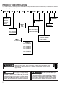
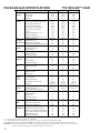
PRODUCT IDENTIFICATION
The model number is used for positive identification of component parts used in manufacturing. Please use this number
when requesting service or parts information.
G/A
P
G
BRAND:
®
G: Goodman
Brand or
Distinctions
®
A: Amana
Brand
15
24
PRODUCT
SERIES:
SEER
Rating
*
*
MAJOR
REVISION:
HEATING INPUT
070: 69,000 BTUH
090: 92,000 BTUH
115: 115,000 BTUH
140: 138,000 BTUH
VOLTAGE:
1: 208-230V/1ph/60Hz
3: 208-230v/3ph/60Hz
4: 460v/3ph/60Hz
NOMINAL
CAPACITY:
24: 24,000 BTUH
30: 30,000 BTUH
36: 36,000 BTUH
37: 36,000 BTUH
42: 42,000 BTUH
48: 48,000 BTUH
49: 48,000 BTUH
60: 60,000 BTUH
HIGH VOLTAGE!
Disconnect ALL power before servicing or installing this unit. Multiple power
sources may be present. Failure to do so may cause property damage, personal
injury or death.
Goodman will not be responsible
for any injury or property damage
arising from improper service or service procedures. If
you install or perform service on this unit, you assume
responsibility for any personal injury or property damage
which may result. Many jurisdictions require a license to
install or service heating and air conditioning equipment.
2
1
REFRIGERANT:
4: R-410A
PRODUCT
FAMILY:
G: Gas/Electric
WARNING
4
MINOR
REVISION:
PRODUCT
TYPE:
Single Package
Cooling/Heating
WARNING
070
Installation and repair of this unit
should be performed ONLY by individuals meeting (at a minimum) the requirements of an
"entry level technician" as specified by the Air-Conditioning, Heating, and Refrigeration Institute (AHRI). Attempting to install or repair this unit without such background
may result in product damage, personal injury or death.
WARNING
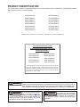
PRODUCT IDENTIFICATION
The model number is used for positive identification of component parts used in manufacturing. Please use this number
when requesting service or parts information.
GPG152407041A*
GPG153009041A*
GPG153609041A*
GPG153709041A*
GPG154209041A*
GPG154811541A*
GPG154911541A*
GPG156014041A*
APG152407041A*
APG153009041A*
APG153609041A*
APG153709041A*
APG154209041A*
APG154811541A*
APG154911541A*
APG156014041A*
* Indicates minor revision & is not used for order entry or inventory management
The models listed below qualify
for the 2009 and 2010 Federal Tax Credits
for Energy Efficiency**
APG152407041A*
APG153007041A*
APG153709041A*
APG154209041A*
APG154911541A*
GPG152407041A*
GPG153007041A*
GPG153709041A*
GPG154209041A*
GPG154911541A*
**Note that these tax credits are subject to specific requirements set
forth in the American Recovery and Reinvestment Act of 2009 and
in the Internal Revenue Code. Goodman recommends that consumers consult a tax professional if they have questions about the
applicability of these credits.
WARNING
The United States Environmental Protection Agency (“EPA”) has issued various regulations regarding the introduction and disposal of refrigerants introduced into this unit. Failure to follow
these regulations may harm the environment and can lead to the imposition of substantial fines.
These regulations may vary by jurisdiction. Should questions arise, contact your local EPA office.
Do not connect or use any device
that is not design certified by
Goodman for use with this unit.
Serious property damage, personal injury, reduced unit
performance and/or hazardous conditions may result
from the use of such non-approved devices.
WARNING
To prevent the risk of property
damage, personal injury, or death,
do not store combustible materials or use gasoline or
other flammable liquids or vapors in the vicinity of this
appliance.
WARNING
3
PRODUCT DESIGN
*PG15 Package Gas Units are designed for outdoor installations only in either residential or light commercial applications and are available in 2, 2-1/2, 3, 3-1/2, 4 & 5 ton sizes.
They are designed for 208/230 volt single phase applications.
The connecting ductwork (Supply and Return) can be connected for either horizontal or vertical airflow. In the vertical
application, a matching Roof Curb is recommended.
A return air filter must be installed behind the return air grille(s)
or provision must be made for a filter in an accessible location within the return air duct. The minimum filter area should
not be less than those sizes listed in the Specification Section. Under no circumstances should the unit be operated
without return air filters.
A 3/4" pipe is provided for removal of condensate water from
the indoor coil. (Do not reduce the drain line size).
Refrigerant flow control is achieved by use of a TXV or orifice.
- These Scroll compressors use "POE" orpolyolester oil which
is NOT compatible with mineral oilbased lubricants like 3GS.
"POE" oil must be used if additional oil is required.
- Compliant scroll compressors perform “quiet” shutdowns
that allow the compressor to restart immediately without the
need for a time delay. This compressor will restart even if the
system has not equalized.
- Operating pressures and amp draws may differ from standard reciprocating compressors. This information may be
found in the “Cooling Performance Data” section.
Some other models of the *PG15 series package units use a
2 stage scroll compressor. The basic scroll design has been
modified with the addition of an internal unloading mechanism that opens a by-pass port in the first compression
pocket, effectively reducing the displacement of the scroll.
The opening and closing of the by-pass port is controlled by
an internal electrically operated solenoid.
*PG15 units use the FasTest Access Fitting System which
consists of a saddle that is either soldered to the suction and
liquid lines or is fastened with a locking nut to the access
fitting box (core) and then screwed into the saddle. NOTE:
The core must not be removed from the saddle until
the refrigerant charge has been removed. Failure to do
so could result in property damage or personal injury.
The single phase units use permanent split capacitors (PSC)
design compressors. Starting components are therefore not
required. A low MFD run capacitor assists the compressor
to start and remains in the circuit during operation.
The *PG15*****41AA models are equipped with X-13 blower
motors. X-13 motors are constant torque motors with very
low power consumption and are energized by a 24V signal
from the ignition control board. The X-13 features an integrated control module.
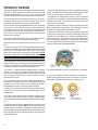
Air for condensing (cooling cycle) is drawn through the outdoor coil by a propeller fan, and is discharged vertically out
the top of the unit. The outdoor coil is designed for .0 static.
No additional restriction (ductwork) shall be applied.
Conditioned air is drawn through the filter(s), field installed,
across the coil and back into the conditioned space by the
indoor blower.
The *PG15 series package units use the Compliant Scroll
compressor; there are a number of design characteristics
which are different from the traditional reciprocating compressor.
- Due to their design Scroll compressors are inherently more
tolerant of liquid refrigerant. NOTE: Even though the compressor section of a Scroll compressor is more tolerant of
liquid refrigerant, continued flood back or flooded start conditions may wash oil from the bearing surfaces causing premature bearing failure.
4
The ZPS modulated scroll uses a single step of unloading
to go from full capacity to approximately 67% capacity. A
single speed, high efficiency motor continues to run while
the scroll modulates between the two capacity steps.
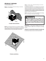
PRODUCT DESIGN
Location and Clearances
NOTE: To ensure proper condensate drainage, unit must be
installed in a level position.
NOTE: To ensure proper condensate drainage, unit must be
installed in a level position.
In installations where the unit is installed above ground level
and not serviceable from the ground (Example: Roof Top installations) the installer must provide service platform for service person with rails or guards in accordance with local codes
or ordinances or in their absence with the latest edition of the
National Fuel Gas Code ANSIZ223.1.
NOTE: Unit can also use roof curb (and platform for leveling,
where necessary) to utilize bottom discharge.
48" MIN
12" MIN
WARNING
36" MIN
(FOR
SERVICE)
.
3"
MIN
12" MIN
36" MIN
(FOR SERVICE)
Outside Slab Installation
NOTE: Roof overhang should be no more than 36" and provisions made to deflect the warm discharge air out from the
overhang. Minimum clearances are required to avoid air recirculation and keep the unit operating at peak efficiency.
TO PREVENT POSSIBLE PROPERTY DAMAGE, THE
UNIT SHOULD REMAIN IN AN UPRIGHT POSITION
DURING ALL RIGGING AND MOVING OPERATIONS.
TO FACILITATE LIFTING AND MOVING IF A CRANE IS
USED, PLACE THE UNIT IN AN ADEQUATE CABLE
SLING.
IMPORTANT: If using bottom discharge with roof curb,
ductwork should be attached to the curb prior to installing
the unit.
Refer to Roof Curb Installation Instructions for proper curb
installation. Curbing must be installed in compliance with
the National Roofing Contractors Association Manual.
Rooftop Installation
5
PRODUCT DESIGN
High Altitude Derate - U.S. Installations Only
IMPORTANT NOTE: The gas/electric units naturally derate
with altitude. Do not attempt to increase the firing rate by
changing orifices or increasing the manifold pressure. This
can cause poor combustion and equipment failure. At all
altitudes, the manifold pressure must be within 0.3 inches
W.C. of that listed on the nameplate for the fuel used. At all
altitudes and with either fuel, the air temperature rise must
be within the range listed on the unit nameplate. Refer to the
Installation Manual provided with the LP kit for conversion
from natural gas to propane gas and for altitude adjustments.
When this package unit is installed at high altitude, the appropriate High Altitude orifice kit must be installed. As alti-
tude increases, there is a natural reduction in the density of
both the gas fuel and combustion air. This kit will provide the
proper design certified input rate within the specified altitude
range. High altitude kits are not approved for use in Canada.
For installations above 2,000 feet, use kit HA-02. The HA-02
kit is used for both Natural and LP gas at high altitudes.
Use LPM-06 propane conversion kit for propane conversions
at altitudes below 2000 feet. Natural gas installations below
2000 feet do not require a kit.
For propane conversions above 2000 feet, high altitude kit
HA-02 is required in addtion to LPM-05 propane conversion
kit.
NATURAL GAS AND LP GAS INSTALLATIONS AT ALTITUDES > 2000 FT
INPUT/BURNER
20,000 BTUH NAT/20,OOO BTUH/L.P.
HIGH ALTITUDE
KIT
ELEVATION ABOVE SEA-LEVEL (FEET)
2000
U.S. BURNER ORIFICE
CANADA BURNER ORIFICE
INPUT/BURNER
HA02
45/55
CANADA BURNER ORIFICE
INPUT/BURNER
CANADA BURNER ORIFICE
6
3000
4000
44/55 44/55 45/56
44/55
48/57
6000
7000
8000
47/56 48/57 48/58 49/58
-
-
-
-
-
-
4500
47/57
5000
6000
7000
8000
45/56 46/57 47/58 47/58
-
-
-
-
25,000 BTUH NAT/20,OOO BTUH/L.P.
HIGH ALTITUDE
KIT
HA02
-
-
5000
ELEVATION ABOVE SEA-LEVEL (FEET)
ELEVATION ABOVE SEA-LEVEL (FEET)
2000
U.S. BURNER ORIFICE
-
4500
22,500 BTUH NAT/20,OOO BTUH/L.P.
HIGH ALTITUDE
KIT
HA02
4000
45/55 47/55 47/56
2000
U.S. BURNER ORIFICE
3000
3000
4000
43/55 43/55 44/56
43/55
-
-
4500
46/57
5000
6000
7000
8000
44/56 44/56 45/57 45/57
-
-
-
-
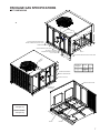
PACKAGE GAS SPECIFICATIONS
UNIT DIMENSIONS
47
51
FLUE EXHAUST
HOOD
18 7/16
16
FLUE EXHAUST
1 3/8
C
A
5 1/2
16
7 15/16
B
SUCTION/LIQUID PRESSURE PORTS
BEHIND COMPRESSOR ACCESS PANEL
2 3/4
COMBUSTION AIR INTAKE
RETURN
B
HEAT EXCHANGE ACCESS PANEL
4 3/4
GAS SUPPLY ENTRANCE
CONDENSATE DRAIN CONNECTION
3/4" NPT FEMALE
SUPPLY
3
EVAPORATOR/CONTROL PANEL ACCESS PANEL
16 1/8
19 1/8
OF
R
TE ITY
N
V
CE RA
G
7 5/16
7 7/8
20
24
DIMENSION
(INCHES)
MEDIUM
LARGE
A
B
32
16
40
18
C
9 1/2
14
POWER WIRE ENTRANCE
CONTROL WIRE ENTRANCE
5 1/4
EXHAUST FLUE HOOD
BLOWER ACCESS PANEL
COMBUSTION
AIR INTAKE
11
5 3/4
22
MEDIUM CHASSIS
*PG15[24-37]
22
LARGE CHASSIS
*PG15[42-60]
11
SUPPLY
RETURN
7
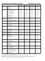
PACKAGE GAS SPECIFICATIONS
COOLING
CAPACITY
*PG152407041AA
*PG153009041AA
*PG153609041AA
*PG153709041AA
HIGH STAGE
23,200
29,000
35,400
35,000
LOW STAGE
N/A
N/A
24,400
N/A
15.0 / 12.0
14.5 / 12.0
15.0 / 11.0
14.5 / 12.0
COOLING CAPACITY, BTUH
SEER / EER
HEATING
CAPACITY
*PG15[24-37]***41AA
BTUH INPUT (US) HIGH FIRE
OUTPUT (US) HIGH FIRE (Natural Gas)
OUTPUT (US) HIGH FIRE (LP)
69,000
92,000
92,000
92,000
55,000
73,500
73,500
73,500
50,000
69,000
69,000
69,000
52,000
69,000
69,000
69,000
OUPUT (US) LOW FIRE (Natural)
41,500
55,000
55,000
55,000
OUTPUT (US) LOW FIRE (LP)
37,000
50,000
50,000
50,000
80
80
80
80
RATED EXTERNAL STATIC (" w.c.)
0.50
0.50
0.50
0.50
TEMPERATURE RISE (°F)
35-65
45-75
45-75
45-75
PRESSURE SWITCH TRIP POINT (" w.c.)
-.33"
-.33"
-.33"
-.33"
208-230/1/60
208-230/1/60
208-230/1/60
208-230/1/60
BTUH INPUT (US) LOW FIRE
A.F.U.E.
UNIT
VOLTAGE (NAMEPLATE)
ELECTRICAL
UNIT AMPS (TOTAL)
18.7
17.5
22.2
20.1
SPECIFICATION
MINIMUM CIRCUIT AMPACITY
22.1
21
26.5
24.2
MAXIMUM OVERCURRENT PROTECTION(3)
30
35
40
40
HEATING
NUMBER OF BURNERS
3
4
4
4
SECTION
ORIFICE SIZE NATURAL
43
43
43
43
ORIFICE SIZE LP
55
55
55
55
TYPE
Scroll
Scroll
Scroll
Scroll
RATED LOAD AMPS
13.5
14.1
16.7
16.7
LOCKED ROTOR AMPS
58.3
73
82
79
CONDENSER
HORSEPOWER
1/6
1/4
1/4
1/4
FAN MOTOR
RPM
815
830
1075
830
FULL LOAD AMPS
1.10
1.5
1.4
1.5
LOCKED ROTOR AMPS
1.7
3.0
2.9
3.0
BLADE DIAMETER (INCHES)
22
22
22
22
3
3
3
3
CFM
2400
2700
2700
2700
CONDENSER
FACE AREA - SQ. FT.
12.3
12.3
12.3
12.3
COIL
NUMBER OF ROWS
1
2
1
2
FINS PER INCH
22
16
22
16
COMPRESSOR
CONDENSER
FAN
NUMBER OF BLADES
EVAPORATOR
HORSEPOWER - NO. OF SPEEDS
1/2 - X-13
1/2 - X-13
1/2 - X-13
1/2 - X-13
BLOWER
FULL LOAD AMPS
4.1
1.86
4.1
1.86
MOTOR
LOCKED ROTOR AMPS
N/A
N/A
N/A
N/A
MOTOR SPEED TAP - COOLING
T4
T3, T4
T3, T4
T3, T4
724 / 1.21
960 / 3.06
640 / 0.98
960 / 3.06
960 / 3.06
RPM / AMPS
EVAPORATOR
DIAMETER X WIDTH (INCHES)
10 x 8
10 x 9
10 x 9
10 x 9
BLOWER
RATED SCFM COOLING
845
1050
800 / 1225
1050
MAX EXTERNAL STATIC PRESS ("w.c.)
0.5
0.5
0.5
0.5
EVAPORATOR
FACE AREA - SQ. FT.
4.33
4.33
4.33
4.33
COIL
NUMBER OF ROWS
2
3
4
4
FINS PER INCH
14
14
14
14
4.2
FILTER SIZE - SQ. FT.(2)
2.7
4.2
4.2
DRAIN SIZE (INCHES)
3/4
3/4
3/4
3/4
HEATING
PRIMARY LIMIT SETTING (°F)
160
160
160
160
LIMITS
AUXILIARY LIMIT SETTING (°F)
150
150
150
150
ROLLOUT LIMIT SETTING (°F)
300
300
300
300
GENERAL
EXPANSION DEVICE
TXV
0.065
TXV
TXV
INFORMATION
REFRIGERANT CHARGE R-410A (Oz.)
81
102
99
112
1 1/8
1 1/8
1 1/8
1 1/8
POWER SUPPLY ENTRANCE SIZE (INCHES)
LOW VOLTAGE ENTRANCE SIZE (INCHES)
7/8
7/8
7/8
7/8
SHIPPING WEIGHT LBS.
439
475
480
480
OPERATING WEIGHT LBS.
417
453
458
458
(1) Units installed in Canada are certifed only to 4500 feet.
(2) Calculated external filter size based on air velocity of 300 ft/min. and applies to disposable filters only.
(3) Maximum Overcurrent Protection Device: MUST use Time Delay Fuse or HACR type Circuit Breaker of the same size as noted.
IMPORTANT: While this data is presented as a guide, it is important to electrically connect the unit and properly size wires and fuses/circuit
breakers in accordance with the National Electrical Code and/or all local codes.
8
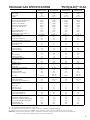
PACKAGE GAS SPECIFICATIONS
*PG154211541AA
*PG15[42-60]***41AA
*PG154811541AA
*PG154911541AA
*PG156014041AA
56,500
COOLING CAPACITY, BTUH
HIGH STAGE
40,000
47,500
47,000
LOW STAGE
N/A
35,000
33,000
41,000
14.5 / 12.0
15.0 / 11.0
15.0 / 12.0
14.0 / 10.1
SEER/EER
BTUH INPUT (US) HIGH FIRE
115,000
115,000
115,000
138,000
OUTPUT (US) HIGH FIRE (Natural Gas)
92,000
92,000
92,000
110,200
OUTPUT (US) HIGH FIRE (LP)
83,000
83,000
83,000
99,000
86,000
86,000
86,000
103,000
BTUH INPUT (US) LOW FIRE
OUPUT (US) LOW FIRE (Natural)
69,000
69,000
69,000
83,000
OUTPUT (US) LOW FIRE (LP)
62,000
62,000
62,000
74,000
A.F.U.E.
RATED EXTERNAL STATIC (" w.c.)
TEMPERATURE RISE (°F)
PRESSURE SWITCH TRIP POINT (" w.c.)
VOLTAGE (NAMEPLATE)
80
80
80
80
0.50
0.50
0.50
0.50
45-75
45-75
45-75
45-75
-.33"
-.33"
-.33"
-.33"
208-230/1/60
208-230/1/60
208-230/1/60
208-230/1/60
UNIT AMPS (TOTAL)
22.2
29.4
25.5
35.6
MINIMUM CIRCUIT AMPACITY
26.6
34.8
30.8
42.1
MAXIMUM OVERCURRENT PROTECTION(3)
NUMBER OF BURNERS
40
50
50
60
5
5
5
6
ORIFICE SIZE NATURAL
43
43
43
43
ORIFICE SIZE LP
55
55
55
55
Scroll
Scroll
Scroll
Scroll
RATED LOAD AMPS
17.9
21.2
21.2
25.6
LOCKED ROTOR AMPS
112
96
96
118
HORSEPOWER
1/4
1/3
1/4
1/3
1075
1075
1075
1075
TYPE
RPM
FULL LOAD AMPS
1.4
2.5
1.4
2.5
LOCKED ROTOR AMPS
2.9
5.8
2.9
5.2
BLADE DIAMETER (INCHES)
22
22
22
22
3
4
3
4
CFM
3500
3500
3500
3500
FACE AREA - SQ. FT.
15.3
15.3
15.3
15.3
2
2
2
2
16
16
16
16
NUMBER OF BLADES
NUMBER OF ROWS
FINS PER INCH
HORSEPOWER - NO. OF SPEEDS
3/4 - X-13
3/4 - X-13
3/4 - X-13
1 - X-13
FULL LOAD AMPS
2.87
6.00
2.87
7.60
LOCKED ROTOR AMPS
N/A
N/A
N/A
N/A
T3, T4
T3, T4
T3, T4
T3,T4
RPM / AMPS
890 / 3.8
647 / 1.66
890 / 3.8
890 / 3.8
778 / 1.98
1030 / 5.7
DIAMETER X WIDTH (INCHES)
11 x 10
11 x 10
11 x 10
11 x 10
1200
1100 / 1510
1300
1300 / 1810
MOTOR SPEED TAP - COOLING
RATED SCFM COOLING
MAX EXTERNAL STATIC PRESS ("w.c.)
0.5
0.5
0.5
0.5
FACE AREA - SQ. FT.
5.67
5.67
5.67
5.67
NUMBER OF ROWS
4
4
4
4
FINS PER INCH
14
14
14
14
6.3
FILTER SIZE - SQ. FT.( 2)
5.1
5.1
5.1
DRAIN SIZE (INCHES)
3/4
3/4
3/4
3/4
PRIMARY LIMIT SETTING (° F)
170
170
170
160
150
AUXILIARY LIMIT SETTING (°F)
150
150
150
ROLLOUT LIMIT SETTING (°F)
300
300
300
300
0.072
TXV
TXV
TXV
EXPANSION DEVICE
REFRIGERANT CHARGE R-410A (Oz.)
POWER SUPPLY ENTRANCE SIZE (INCHES)
162
169
167
177
1 1/8
1 1/8
1 1/8
1 1/8
LOW VOLTAGE ENTRANCE SIZE (INCHES)
7/8
7/8
7/8
7/8
SHIPPING WEIGHT LBS.
560
560
560
565
OPERATING WEIGHT LBS.
538
538
538
543
(1) Units installed in Canada are certifed only to 4500 feet.
(2) Calculated external filter size based on air velocity of 300 ft/min. and applies to disposable filters only.
(3) Maximum Overcurrent Protection Device: MUST use Time Delay Fuse or HACR type Circuit Breaker of the same size as noted.
IMPORTANT: While this data is presented as a guide, it is important to electrically connect the unit and properly size wires and fuses/circuit
breakers in accordance with the National Electrical Code and/or all local codes.
9
PACKAGE GAS SPECIFICATIONS
COOLING
CAPACITY
*PG153609041AB
* PG154811541AB
*PG156014041AB
HIGH STAGE
35,400
47,500
56,500
LOW STAGE
24,400
35,000
41,000
15.0 / 11.0
15.0 / 11.0
14.0 / 10.1
COOLING CAPACITY, BT UH
SEER/EER
HEATING
CAPACITY
*PG15[36-60]***41AB
BTUH INPUT (US) HIGH FIRE
92,000
115,000
138,000
OUTPUT (US) HIGH FIRE (Natural Gas)
73,500
92,000
110,200
OUTPUT (US) HIGH FIRE (LP)
69,000
83,000
99,000
69,000
86,000
103,500
OUPUT (US) LOW FIRE (Natural)
55,000
69,000
83,000
OUTPUT (US) LOW FIRE (LP)
50,000
62,000
74,000
80
80
80
0.50
0.50
0.50
TEMPERATURE RISE (°F)
45-75
45-75
45-75
PRESSURE SWITCH TRIP POINT (" w.c.)
-.33"
-.33"
-.33"
208-230/1/60
208-230/1/60
208-230/1/60
BTUH INPUT (US) LOW FIRE
A.F.U.E.
RATED EXTERNAL STATIC (" w.c.)
UNIT
VOLTAGE (NAMEPLATE)
EL ECTRICAL
UNIT AMPS (TOTAL)
22.3
20.1
34.6
26.5
34.8
42.1
MAXIMUM OVERCURRENT PROTECTION
40
50
60
HEATING
NUMBER OF BURNERS
4
5
6
SECTION
ORIFICE SIZE NATURAL
43
43
43
SPECIFICATION MINIMUM CIRCUIT AMPACITY
( 3)
ORIFICE SIZE LP
COMPRESSOR
TYPE
RATED LOAD AMPS
55
55
55
Scroll
Scroll
Scroll
16.7
21.2
25.8
LOCKED ROTOR AMPS
82
96
118
CONDENSER
HORSEPOWER
1/4
1/4
1/4
FAN MOTOR
RPM
830
1075
1075
FULL LOAD AMPS
1.5
1.4
1.4
LOCKED ROTOR AMPS
3.0
5.2
5.2
BLADE DIAMETER (INCHES)
22
22
22
3
3
3
CFM
2700
3500
3500
CONDENSER
FACE AREA - SQ. FT.
12.3
15.3
15.3
COIL
NUMBER OF ROWS
1
2
2
FINS PER INCH
22
16
16
1 - X-13
CONDENSER
FAN
NUMBER OF BLADES
EVAPORATOR
HORSEPOWER - NO. OF SPEEDS
1/2 - X-13
3/4 - X-13
BLOWER
FULL LOAD AMPS
4.1
6
7.6
MOTOR
LOCKED ROTOR AMPS
N/A
N/A
N/A
MOT OR SPEED TAP - COOLING
RPM / AMPS
EVAPORATOR
DIAMETER X WIDT H (INCHES)
BLOWER
RATED SCFM COOLING
T3, T4
T3, T4
T3,T 4
640 / 0.98
960 / 3.06
647 / 1.66
890 / 3.8
778 / 1.98
1030 / 5.7
10 x 9
11 x 10
11 x 10
800 / 1225
1100 / 1510
1300 / 1810
MAX EXTERNAL STATIC PRESS ("w.c.)
0.5
0.5
0.5
EVAPORATOR
FACE AREA - SQ. FT.
4.33
5.67
5.67
COIL
NUMBER OF ROWS
4
4
4
FINS PER INCH
14
14
14
(2)
4.2
5.1
6.3
DRAIN SIZE (INCHES)
3/4
3/4
3/4
HEATING
PRIMARY LIMIT SETTING (°F)
160
170
160
LIMITS
AUXILIARY LIMIT SETTING (°F)
150
150
150
FILTER SIZE - SQ. FT .
ROLLOUT LIMIT SETTING (°F )
300
300
300
GENERAL
EXPANSION DEVICE
TXV
TXV
TXV
INFORMATION
REFRIGERANT CHARGE R-410A (Oz.)
102
172
180
POWER SUPPLY ENTRANCE SIZ E (INCHES
1 1/8
1 1/8
1 1/8
LOW VOLTAGE ENTRANCE SIZE (INCHES)
7/8
7/8
7/8
SHIPPING WEIGHT LBS.
480
560
565
OPERATING WEIGHT LBS.
458
538
543
(1) Units installed in Canada are certifed only to 4500 feet.
(2) Calculated external filter size based on air velocity of 300 ft/min. and applies to disposable filters only.
(3) Maximum Overcurrent Protection Device: MUST use Time Delay Fuse or HACR type Circuit Breaker of the same size as noted.
IMPORTANT: While this data is presented as a guide, it is important to electrically connect the unit and properly size wires and fuses/circuit
breakers in accordance with the National Electrical Code and/or all local codes.
10
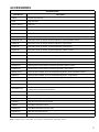
ACCESSORIES
ACCESSORIES
Part Number
Description
LPM-06
Propane Conversion Kit
HA-02
High Altitude Kit
PGC101/102/103
Roof Curb
PGED101/102
Downflow Economizer, Small and Medium Chassis
PGED103
Downflow Economizer, Large Chassis
PGEH101/102
Horizontal Economizer, Small and Medium Chassis
PGEH103
Horizontal Economizer, Large Chassis
PGMDD101/102
Manual 25% Fresh Air Damper Downflow Application, Small and Medium Chassis
PGMDD103
Manual 25% Fresh Air Damper Downflow Application, Large Chassis
PGMDH101
Manual 25% Fresh Air Damper Horizontal Application, Small Chassis
PGMDH102
Manual 25% Fresh Air Damper Horizontal Application, Medium Chassis
PGMDH103
Manual 25% Fresh Air Damper Horizontal Application, Large Chassis
PGMDMD101/102
Motorized 25% Fresh Air Damper Downflow Application,Small and Medium Chassis
PGMDMD103
Motorized 25% Fresh Air Downflow Application, Large Chassis
PGMDMH101
Motorized 25% Fresh Air Damper Horizontal Application, Small Chassis
PGMDMH102
Motorized 25% Fresh Air Damper Horizontal Application, Medium Chassis
PGMDMH103
Motorized 25% Fresh Air Damper Horizontal Application, Large Chassis
SQRPG101/102
Square to Round Adapter w/ 16" Round Downflow Application, Small and Medium Chassis
SQRPG103
Square to Round Adapter w/ 18" Round Downflow Application, Large Chassis
SQRPGH101/102
Square to Round Adapter w/ 16" Round Horizontal Application, Small and Medium Chassis
SQRPGH103
Square to Round Adapter w/ 18" Round Horizontal Application, Large Chassis
PGFR101/102/103
Internal Filter Rack All Chassis
GPGHFR101-103
External Horizontal Filter Rack for Goodman/Amana Gas/Electric
& Multi-position Package Units All Chassis
CDK36
Flush Mount Concentric Duct Kit
CDK36515
Flush Mount Concentric Duct Kit w/ Filter
CDK36530
Step Down Concentric Duct Kit
CDK36535
Step Down Concentric Duct Kit w/ Filter
CDK4872
Flush Mount Concentric Duct Kit
CDK4872515
Flush Mount Concentric Duct Kit w/ Filter
CDK4872530
Step Down Concentric Duct Kit
CDK4872535
Step Down Concentric Duct Kit w/ Filter
NOTE: Complete lineup of thermostats can be found in the Thermostat Specification Sheets.
11
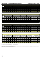
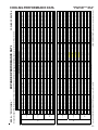
*PG15[24-36]***41A*
BLOWER PERFORMANCE DATA
*PG15240701A* - Rise Range: 35° - 65°
Unit
Static
0.1
0.2
0.3
0.4
0.5
0.6
0.7
0.8
T1 - 1st Stage Heating Speed
CFM
WATTS AMPS
RISE
742
84
0.75
52
677
89
0.82
57
631
97
0.90
62
575
101
0.92
X
526
111
1.01
X
-
T2 - 2nd Stage Heating Speed
CFM WATTS AMPS
RISE
907
134
1.18
57
857
140
1.24
61
814
149
1.32
64
761
154
1.33
X
727
165
1.41
X
678
169
1.47
X
-
T3 - Cooling Speed
CFM WATTS AMPS
857
116
1.04
816
126
1.16
760
131
1.18
721
140
1.25
670
145
1.31
629
155
1.39
-
T4 - Cooling Spped
CFM WATTS AMPS
907
134
1.18
857
140
1.24
814
149
1.32
761
154
1.33
727
165
1.41
678
169
1.47
-
T5 - Cooling Spped
CFM WATTS
AMPS
1,040
185
1.33
988
198
1.40
949
208
1.42
903
213
1.49
871
222
1.55
824
228
1.58
-
*PG153009041A* - Rise Range: 45° -75°
Unit
Static
0.1
0.2
0.3
0.4
0.5
0.6
0.7
0.8
T1 - 1st Stage Heating Speed
CFM
1,065
1,003
961
913
855
814
749
713
WATTS
168
174
185
195
202
212
218
227
AMPS
1.42
1.48
1.55
1.62
1.69
1.76
1.82
1.87
RISE
49
52
54
57
60
63
69
72
T2 - 2nd Stage Heating Speed
CFM
1,255
1,217
1,165
1,113
1,073
1,018
991
-
WATTS
257
269
274
285
296
302
313
-
AMPS
2.10
2.19
2.21
2.30
2.36
2.41
2.48
-
RISE
55
57
59
62
64
68
70
-
T3 Cooling Spped
CFM WATTS
1,148
170
1,092
176
1,044
184
994
194
929
210
811
222
763
224
715
236
AMPS
1.55
1.66
1.72
1.77
1.89
1.99
2.03
2.07
T4 - Cooling Speed
CFM
1,148
1,092
1,044
994
929
811
763
715
WATTS
170
176
184
194
210
222
224
236
AMPS
1.55
1.66
1.72
1.77
1.89
1.99
2.03
2.07
T5 - Cooling Speed
CFM
1,333
1,293
1,237
1,193
1,158
1,101
-
WATTS
304
314
321
333
341
345
-
AMPS
2.41
2.48
2.54
2.71
2.77
2.78
-
*PG153609041A* - Rise Range: 45° -75°
Unit
Static
0.1
0.2
0.3
0.4
0.5
0.6
0.7
0.8
T1 - 1st Stage Heating Speed
CFM
WATTS AMPS
RISE
1,065
168
1.42
49
1,003
174
1.48
52
961
185
1.55
54
913
195
1.62
57
855
202
1.69
60
814
212
1.76
63
749
218
1.82
69
713
227
1.87
72
T2 - 2nd Stage Heating Speed
CFM WATTS AMPS
RISE
1,255
257
2.10
55
1,217
269
2.19
57
1,165
274
2.21
59
1,113
285
2.30
62
1,073
296
2.36
64
1,018
302
2.41
68
991
313
2.48
70
-
T3 - 1st Stage Cooling
CFM WATTS AMPS
924
120
1.08
863
128
1.14
812
138
1.24
745
145
1.27
702
154
1.35
643
159
1.37
601
168
1.44
502
173
1.52
T4 - 2nd Stage Cooling
CFM WATTS AMPS
1,333
304
2.41
1,293
314
2.48
1,237
321
2.54
1,193
333
2.71
1,158
341
2.77
1,101
345
2.78
-
T5 - Cooling Speed
CFM WATTS
AMPS
1,418
360
2.92
1,375
371
3.00
1,316
376
3.05
1,279
387
3.13
1,245
392
3.19
1,193
400
3.22
-
T2 - 2nd Stage Heating Speed
T3 Cooling Spped
T4 Cooling Speed
T5 - Cooling Speed
*PG153709041A* - Rise Range: 45° -75°
T1 - 1st Stage Heating Speed
Unit
Static
0.1
0.2
0.3
0.4
0.5
0.6
0.7
0.8
CFM
1,065
1,003
961
913
855
814
749
713
WATTS
168
174
185
195
202
212
218
227
AMPS
1.42
1.48
1.55
1.62
1.69
1.76
1.82
1.87
RISE
49
52
54
57
60
63
69
72
CFM
1,255
1,217
1,165
1,113
1,073
1,018
991
-
WATTS
257
269
274
285
296
302
313
-
AMPS
2.10
2.19
2.21
2.30
2.36
2.41
2.48
-
RISE
55
57
59
62
64
68
70
-
CFM WATTS
1,148
170
1,092
176
1,044
184
994
194
929
210
811
222
763
224
715
236
AMPS
1.55
1.66
1.72
1.77
1.89
1.99
2.03
2.07
CFM
1,148
1,092
1,044
994
929
811
763
715
WATTS
170
176
184
194
210
222
224
236
AMPS
1.55
1.66
1.72
1.77
1.89
1.99
2.03
2.07
CFM
1,418
1,375
1,316
1,279
1,245
1,193
-
WATTS
360
371
376
387
392
400
-
AMPS
2.92
3.00
3.05
3.13
3.19
3.22
-
X = Outside of Temperature Rise Range - Not Recommended.
NOTE: The shaded area indicates ranges in excess of maximum external static pressure allowable when heating. For satisfactory operation,
external static pressure should not exceed 0.5" w.c.
12
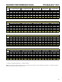
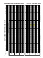
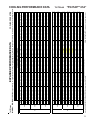
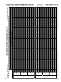
BLOWER PERFORMANCE DATA
*PG15[42-60]***41A*
*PG154211541A* - Rise Range: 45° -75°
T1 - 1st Stage Heating Speed
T2 - 2nd Stage Heating Speed
T3 Cooling Spped
T4 Cooling Speed
T5 - Cooling Speed
Unit
Static
CFM
WATTS
AMPS
RISE
CFM
WATTS
AMPS
RISE
CFM
WATTS
AMPS
CFM
WATTS
AMPS
CFM
WATTS
AMPS
0.1
0.2
0.3
0.4
0.5
0.6
0.7
0.8
1,065
1,003
961
913
855
814
749
713
168
174
185
195
202
212
218
227
1.42
1.48
1.55
1.62
1.69
1.76
1.82
1.87
49
52
54
57
60
63
69
72
1,255
1,217
1,165
1,113
1,073
1,018
991
-
257
269
274
285
296
302
313
-
2.10
2.19
2.21
2.30
2.36
2.41
2.48
-
55
57
59
62
64
68
70
-
1,335
1,274
1,204
1,136
1,069
1,009
946
886
260
268
281
287
300
312
319
331
1.01
1.04
1.10
1.11
1.15
1.19
1.22
1.27
1,468
1,412
1,346
1,275
1,221
1,170
1,105
1,042
337
349
359
363
370
386
397
406
1.28
1.33
1.37
1.40
1.44
1.47
1.52
1.54
1,619
1,560
1,504
1,441
1,380
1,325
1,268
1,198
431
445
456
463
475
489
495
502
1.64
1.69
1.71
1.76
1.80
1.84
1.88
1.90
*PG154811541A* - Rise Range: 45° - 75°
Unit
Static
0.1
0.2
0.3
0.4
0.5
0.6
0.7
0.8
T1 - 1st Stage Heating Speed
CFM
WATTS AMPS
RISE
1140
178
1.52
56
1090
188
1.57
59
1038
199
1.67
62
980
212
1.76
65
914
220
1.79
70
852
231
1.9
75
806
242
1.97
X
741
248
2.01
X
T2 - 2nd Stage Heating Speed
CFM WATTS AMPS
RISE
1417
305
2.46
61
1374
318
2.56
63
1322
327
2.68
65
1273
338
2.72
68
1224
352
2.82
70
1176
365
2.88
73
1121
379
2.93
X
1068
391
2.98
X
T3 - 1st Stage Cooling
CFM WATTS AMPS
1,140
178
1.52
1,090
188
1.57
1,038
199
1.67
980
212
1.76
914
220
1.79
852
231
1.90
806
242
1.97
741
248
2.01
T4 - 2nd Stage Cooling
CFM WATTS AMPS
1,616
436
3.34
1,573
449
3.46
1,527
462
3.59
1,485
474
3.69
1,443
489
3.80
1,399
502
3.86
1,356
513
3.99
1,307
525
4.05
T5 - Cooling Spped
CFM
WATTS
AMPS
1,696
503
4.04
1,650
517
4.15
1,608
530
4.25
1,566
543
4.39
1,523
556
4.43
1,480
569
4.55
1,441
580
4.65
-
T2 - 2nd Stage Heating Speed
CFM WATTS AMPS
RISE
61
1417
305
2.46
1374
318
2.56
63
1322
327
2.68
65
1273
338
2.72
68
1224
352
2.82
70
1176
365
2.88
73
1121
379
2.93
X
1068
391
2.98
X
T3 - 1st Stage Cooling
CFM WATTS AMPS
1140
178
1.52
1090
188
1.57
1038
199
1.67
980
212
1.76
914
220
1.79
852
231
1.9
806
242
1.97
741
248
2.01
T4 - 2nd Stage Cooling
CFM WATTS AMPS
1,468
1,412
1,346
1,275
1,221
1,170
1,105
1,042
T5 - Cooling Speed
CFM
WATTS
AMPS
1,696
503
4.04
1,650
517
4.15
1,608
530
4.25
1,566
543
4.39
1,523
556
4.43
1,480
569
4.55
1,441
580
4.65
-
T3 - 1st Stage Cooling
CFM WATTS AMPS
1,379
246
1.95
1,322
258
2.03
1,268
266
2.10
1,187
280
2.19
1,133
287
2.23
1,068
294
2.29
1,026
307
2.38
-
T4 - 2nd Stage Cooling
CFM WATTS AMPS
1,919
700
4.81
1,862
714
4.94
1,810
720
5.01
1,755
734
5.07
1,705
743
5.09
1,647
748
5.16
-
*PG154911541A* - Rise Range: 45° - 75°
Unit
Static
0.1
0.2
0.3
0.4
0.5
0.6
0.7
0.8
T1 - 1st Stage Heating Speed
CFM
WATTS AMPS
RISE
56
1140
178
1.52
1090
188
1.57
59
1038
199
1.67
62
980
212
1.76
65
914
220
1.79
70
852
231
1.9
75
806
242
1.97
X
741
248
2.01
X
*PG156014041A* - Rise Range: 45° - 75° High
Unit
Static
0.1
0.2
0.3
0.4
0.5
0.6
0.7
0.8
T1 - 1st Stage Heating Speed
CFM
WATTS AMPS
RISE
1773
488
3.64
43
1713
501
3.73
45
1693
509
3.78
45
1653
518
3.84
46
1597
529
3.91
48
1534
541
3.99
50
1485
552
4.09
52
-
337
349
359
363
370
386
397
406
1.28
1.33
1.37
1.40
1.44
1.47
1.52
1.54
30° - 60° Low
T2 - 2nd Stage Heating Speed
CFM WATTS AMPS
RISE
1773
488
3.64
58
1713
501
3.73
61
1693
509
3.78
61
1653
518
3.84
63
1597
529
3.91
65
1534
541
3.99
68
1485
552
4.09
70
-
T5 - Cooling Speed
CFM
WATTS
AMPS
2,115
783
5.54
2,078
787
5.57
2,009
802
5.67
1,953
813
5.87
1,933
805
5.77
-
X = Outside of Temperature Rise Range - Not Recommended.
NOTE: The shaded area indicates ranges in excess of maximum external static pressure allowable when heating. For satisfactory operation,
external static pressure should not exceed 0.5" w.c.
13
14
10
20
30
40
50
60
70
30
80
90
100
40
50
60
700
600 CFM
90
100
2000
2200
2400 CFM
1800
1600
1400
OUTPUT BTU/HR x 1000
80
1200
1100
1000
900
70
800
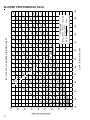
FORMULAS
110
120
130
140
BTU OUTPUT = CFM x 1.08 x RISE
BTU OUTPUT
RISE =
÷ CFM
1.08
BTU OUTPUT vs TEMPERATURE RISE CHART
150
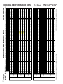
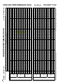
BLOWER PERFORMANCE DATA
TEMPERATURE RISE
EXPANDED PERFORMANCE DATA
20.4
0.72
18
1.46
6.8
218
105
23.1
0.89
20
1.52
7.1
229
110
22.4
0.85
21
1.51
7.0
227
109
20.7
0.82
21
1.47
6.9
220
106
MBh
S/T
Delta T
KW
AMPS
HI PR
LO PR
MBh
S/T
Delta T
KW
AMPS
HI PR
LO PR
MBh
S/T
Delta T
KW
AMPS
HI PR
LO PR
MBh
S/T
Delta T
KW
AMPS
HI PR
LO PR
845
739
951
739
845
23.1
0.76
19
1.54
7.2
244
116
21.3
0.73
19
1.50
7.0
237
113
23.8
0.80
18
1.55
7.2
246
117
21.1
0.60
16
1.49
7.0
234
112
22.9
0.62
16
1.53
7.1
241
115
23.6
0.65
15
1.54
7.2
244
116
25.0
0.57
16
1.59
7.4
257
127
23.1
0.55
16
1.55
7.2
250
123
25.8
0.60
15
1.60
7.4
260
128
23.1
0.42
12
1.54
7.1
247
122
25.1
0.43
12
1.57
7.3
255
126
25.8
0.45
11
1.59
7.4
257
127
26.8
0.37
11
1.64
7.6
269
135
24.8
0.36
11
1.60
7.4
260
131
27.7
0.39
10
1.65
7.6
271
136
-
-
-
21.9
0.88
21
1.62
7.5
254
115
20.2
0.85
21
1.58
7.3
247
112
22.6
0.92
20
1.64
7.6
257
117
19.9
0.75
18
1.57
7.3
244
111
21.6
0.77
18
1.61
7.4
252
114
22.2
0.81
17
1.62
7.5
254
115
22.6
0.79
19
1.66
7.7
274
123
20.8
0.76
20
1.62
7.5
265
119
23.3
0.83
19
1.67
7.7
276
124
20.6
0.62
16
1.60
7.4
263
118
22.3
0.65
16
1.64
7.6
271
122
23.0
0.68
15
1.66
7.7
274
123
24.4
0.60
16
1.71
7.9
289
134
22.6
0.57
16
1.67
7.7
280
130
25.2
0.62
15
1.72
7.9
292
135
22.6
0.43
12
1.66
7.6
277
129
24.5
0.45
12
1.70
7.8
286
133
25.2
0.47
11
1.71
7.9
289
134
26.2
0.38
11
1.77
8.1
301
143
24.2
0.37
11
1.72
7.9
292
138
27.0
0.40
10
1.78
8.2
304
144
-
-
-
21.4
0.90
21
1.72
8.0
289
120
19.8
0.87
21
1.68
7.9
280
116
22.0
0.95
20
1.74
8.1
292
121
19.4
0.77
18
1.67
7.8
278
115
21.0
0.79
18
1.71
8.0
286
119
21.7
0.83
17
1.72
8.0
289
120
22.0
0.81
19
1.76
8.2
311
128
20.3
0.78
20
1.72
8.0
302
124
22.7
0.85
19
1.78
8.3
314
129
20.1
0.64
16
1.70
8.0
299
123
21.8
0.66
16
1.75
8.1
308
126
22.5
0.70
15
1.76
8.2
311
128
23.9
0.61
16
1.82
8.4
329
139
22.0
0.59
16
1.77
8.2
319
135
24.6
0.64
15
1.84
8.5
332
141
22.1
0.44
12
1.76
8.2
315
134
23.9
0.46
12
1.80
8.4
325
138
24.6
0.48
11
1.82
8.4
328
139
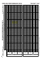
* Entering Indoor Dry Bulb Temperature
NOTE: Shaded area is ACCA (TVA) conditions
High and low pressures are measured at the liquid and suction access fittings.
75
70
22.1
0.75
18
1.49
7.0
224
108
MBh
S/T
Delta T
KW
AMPS
HI PR
LO PR
951
22.7
0.78
17
1.51
7.0
227
109
MBh
S/T
Delta T
KW
AMPS
HI PR
LO PR
25.6
0.39
11
1.88
8.7
343
148
23.6
0.38
11
1.83
8.5
332
144
26.4
0.41
11
1.90
8.8
346
150
-
-
-
20.9
0.93
21
1.82
8.5
329
126
19.3
0.90
22
1.77
8.3
319
122
21.5
0.98
20
1.83
8.6
333
127
19.0
0.79
19
1.76
8.2
316
121
20.5
0.82
18
1.80
8.4
326
125
21.1
0.86
18
1.82
8.5
329
126
21.5
0.83
19
1.86
8.7
354
134
19.8
0.80
20
1.81
8.5
344
130
22.1
0.87
19
1.87
8.7
358
135
19.6
0.66
16
1.79
8.4
340
129
21.3
0.68
16
1.84
8.6
351
133
21.9
0.72
15
1.86
8.7
354
134
23.3
0.63
16
1.92
8.9
374
146
21.5
0.61
16
1.87
8.7
363
142
24.0
0.66
15
1.93
9.0
378
148
21.5
0.46
12
1.85
8.6
359
140
23.3
0.47
12
1.90
8.9
370
145
24.0
0.50
12
1.92
8.9
374
146
19.8
0.97
21
1.89
9.0
370
132
18.3
0.93
21
1.84
8.8
359
128
20.4
1.00
20
1.91
9.0
374
133
18.0
0.82
18
1.83
8.7
356
127
19.5
0.85
18
1.88
8.9
367
131
20.1
0.89
17
1.89
9.0
370
132
20.4
0.86
19
1.93
9.2
399
140
18.9
0.83
20
1.89
8.9
387
136
21.0
0.91
18
1.95
9.2
403
142
18.7
0.69
16
1.87
8.9
383
135
20.2
0.71
16
1.92
9.1
395
139
20.8
0.74
15
1.93
9.2
399
140
22.1
0.65
16
2.00
9.4
421
153
20.4
0.63
16
1.95
9.2
408
149
22.8
0.69
15
2.02
9.5
425
155
20.4
0.47
12
1.93
9.1
404
147
22.2
0.49
12
1.98
9.3
417
152
22.8
0.52
11
2.00
9.4
421
153
23.7
0.42
11
2.07
9.7
439
163
21.9
0.41
11
2.01
9.5
426
158
24.4
0.44
10
2.08
9.8
443
165
-
-
-
18.4
0.98
19
1.96
9.4
409
137
17.0
0.94
20
1.91
9.2
397
132
18.9
1.00
18
1.98
9.5
413
138
16.7
0.83
17
1.89
9.1
393
131
18.1
0.86
17
1.94
9.4
405
135
18.6
0.90
16
1.96
9.4
409
137
63
18.9
0.87
18
2.00
9.6
441
145
17.5
0.84
18
1.95
9.4
427
141
19.5
0.91
17
2.02
9.7
445
147
17.3
0.69
15
1.94
9.3
423
139
18.7
0.72
15
1.99
9.6
436
144
19.3
0.75
14
2.00
9.6
440
145
67
20.5
0.66
15
2.07
9.9
465
159
18.9
0.64
15
2.02
9.7
451
154
21.1
0.69
14
2.09
10.0
470
160
18.9
0.48
11
2.00
9.6
447
152
20.5
0.50
11
2.05
9.8
460
157
21.1
0.52
11
2.07
9.9
465
159
22.0
0.42
10
2.14
10.2
485
169
20.3
0.41
10
2.09
10.0
471
164
22.6
0.45
10
2.16
10.3
490
171
-
-
-
71
KW = Total system power
AMPS: Unit amps (comp.+ evaporator + condenser fan motors)
25.0
0.41
11
1.98
9.2
390
156
23.1
0.39
11
1.93
9.0
379
151
25.7
0.43
11
2.00
9.3
394
157
-
-
-
115
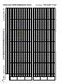
COOLING OPERATION
Design Subcooling, 10 °F + 3 @ the liquid access fitting connection AHRI 95 test conditions. Design Superheat 10 °F + 3 @ the compressor suction access fitting connection.
Outdoor Ambient Temperature
65
75
85
95
105
Entering Indoor Wet Bulb Temperature
67
71
59
63
67
71
59
63
67
71
59
63
67
71
59
63
67
71
59
IDB* Airflow
59
63
MODEL: *PG1524***41A*
COOLING PERFORMANCE DATA
*PG1524***41A*
15
16
MODEL: *PG1524***41A*
EXPANDED PERFORMANCE DATA
21.1
0.90
24
1.48
6.9
222
107
23.9
1.00
23
1.54
7.2
233
113
23.2
0.98
25
1.53
7.1
231
111
21.5
0.94
25
1.49
7.0
224
108
MBh
S/T
Delta T
KW
AMPS
HI PR
LO PR
MBh
S/T
Delta T
KW
AMPS
HI PR
LO PR
MBh
S/T
Delta T
KW
AMPS
HI PR
LO PR
MBh
S/T
Delta T
KW
AMPS
HI PR
LO PR
845
739
951
845
739
21.9
0.91
25
1.53
7.1
241
115
23.7
0.94
24
1.56
7.3
249
119
24.4
0.99
23
1.58
7.3
251
120
21.5
0.84
23
1.51
7.1
239
114
23.3
0.87
22
1.55
7.2
246
117
22.9
0.82
23
1.57
7.3
255
126
24.8
0.85
23
1.61
7.5
263
129
25.6
0.89
22
1.63
7.5
265
131
23.0
0.69
20
1.56
7.3
252
124
24.9
0.71
19
1.60
7.4
260
128
24.4
0.67
20
1.62
7.5
266
134
26.5
0.69
20
1.66
7.7
274
138
27.3
0.72
19
1.68
7.8
277
139
24.6
0.51
16
1.61
7.5
263
132
26.7
0.53
15
1.65
7.7
271
136
21.0
0.98
25
1.61
7.4
252
114
22.7
1.00
25
1.65
7.6
259
118
23.4
1.00
23
1.66
7.7
262
119
20.6
0.93
24
1.60
7.4
249
113
22.3
0.97
23
1.64
7.6
257
117
21.4
0.94
25
1.64
7.6
271
121
23.1
0.98
25
1.68
7.8
279
125
23.8
1.00
23
1.70
7.8
282
126
21.0
0.87
23
1.63
7.5
268
120
22.8
0.91
22
1.67
7.7
276
124
22.4
0.85
24
1.70
7.8
286
133
24.2
0.88
23
1.74
8.0
295
137
25.0
0.92
22
1.75
8.0
298
138
22.5
0.71
20
1.68
7.7
283
131
24.4
0.74
20
1.73
7.9
292
135
23.9
0.69
20
1.75
8.0
298
141
25.9
0.72
20
1.80
8.2
307
146
26.6
0.75
19
1.81
8.3
310
147
24.0
0.53
16
1.74
8.0
295
140
26.0
0.55
16
1.78
8.2
304
144
20.5
1.00
25
1.71
8.0
286
119
22.2
1.00
24
1.75
8.2
295
122
22.8
1.00
22
1.77
8.2
298
124
20.1
0.95
24
1.70
7.9
283
118
21.8
0.99
23
1.74
8.1
292
121
20.9
0.97
25
1.75
8.1
308
126
22.6
1.00
25
1.79
8.3
317
130
23.3
1.00
23
1.81
8.4
321
131
20.5
0.90
23
1.73
8.1
305
125
22.3
0.93
22
1.78
8.3
314
129
21.8
0.87
24
1.80
8.4
325
138
23.7
0.90
23
1.85
8.6
335
142
24.4
0.95
22
1.87
8.6
339
144
21.9
0.73
20
1.79
8.3
322
136
23.8
0.76
20
1.84
8.5
332
141
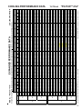
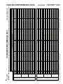
* Entering Indoor Dry Bulb Temperature
NOTE: Shaded area is AHRI Rating Conditions
High and low pressures are measured at the liquid and suction access fittings.
85
80
22.8
0.93
23
1.52
7.1
229
110
MBh
S/T
Delta T
KW
AMPS
HI PR
LO PR
23.3
0.71
20
1.86
8.6
339
147
25.2
0.73
20
1.91
8.8
350
151
26.0
0.77
19
1.93
8.9
353
153
23.5
0.54
16
1.85
8.6
336
145
25.4
0.56
16
1.90
8.8
346
150
20.0
1.00
25
1.80
8.4
326
125
21.6
1.00
24
1.85
8.6
336
129
22.3
1.00
22
1.86
8.7
339
130
19.6
0.99
24
1.78
8.4
323
123
21.3
1.00
23
1.83
8.6
333
127
20.3
1.00
25
1.84
8.6
351
133
22.0
1.00
24
1.89
8.8
362
137
22.7
1.00
22
1.90
8.9
365
138
20.0
0.92
23
1.82
8.5
347
131
21.7
0.96
23
1.87
8.8
358
135
21.3
0.90
24
1.90
8.9
370
145
23.1
0.93
23
1.95
9.1
382
149
23.8
0.98
22
1.97
9.1
386
151
21.4
0.75
20
1.88
8.8
367
143
23.2
0.78
20
1.93
9.0
378
148
19.0
1.00
24
1.88
8.9
367
131
20.5
1.00
22
1.92
9.1
378
135
21.2
1.00
20
1.94
9.2
382
136
18.6
1.02
24
1.86
8.8
363
129
20.2
1.00
22
1.91
9.0
374
133
19.3
1.00
24
1.92
9.1
395
139
20.9
1.00
23
1.97
9.3
407
143
21.6
1.00
21
1.98
9.4
411
145
19.0
0.96
23
1.90
9.0
391
138
20.6
0.99
22
1.95
9.2
403
142
20.2
0.93
23
1.98
9.3
417
152
21.9
0.97
23
2.03
9.6
430
156
22.6
1.00
22
2.05
9.7
434
158
20.3
0.78
20
1.96
9.3
412
150
22.0
0.81
19
2.02
9.5
425
155
21.6
0.76
20
2.05
9.7
435
162
23.4
0.79
20
2.10
9.9
448
167
24.1
0.82
19
2.12
10.0
452
168
21.7
0.58
16
2.03
9.6
430
160
23.6
0.61
16
2.08
9.8
444
165
17.6
1.00
22
1.94
9.3
405
135
19.0
1.00
21
1.99
9.6
418
139
19.6
1.00
19
2.01
9.7
422
141
17.3
1.03
22
1.93
9.3
401
134
18.7
1.00
20
1.98
9.5
413
138
17.9
1.00
22
1.99
9.5
436
144
19.4
1.00
21
2.04
9.8
449
148
20.0
1.00
19
2.05
9.9
454
150
17.6
0.97
21
1.97
9.5
432
142
19.1
1.00
21
2.02
9.7
445
147
18.7
0.94
22
2.05
9.8
460
157
20.3
0.98
22
2.11
10.1
475
162
20.9
1.00
20
2.12
10.2
479
163
18.8
0.79
18
2.03
9.7
456
155
20.4
0.82
18
2.09
10.0
470
160
67
21.0
0.86
17
2.11
10.1
475
162
20.0
0.76
19
2.12
10.2
480
167
21.7
0.79
19
2.18
10.4
495
172
22.3
0.83
18
2.20
10.5
500
174
20.1
0.59
15
2.10
10.1
475
165
21.8
0.61
14
2.16
10.3
490
171
71
22.5
0.64
14
2.18
10.4
495
172
KW = Total system power
AMPS: Unit amps (comp.+ evaporator + condenser fan motors)
22.7
0.73
21
1.96
9.1
386
154
24.6
0.76
20
2.01
9.4
398
159
25.4
0.79
19
2.03
9.4
402
161
22.9
0.56
16
1.95
9.1
382
153
24.8
0.58
16
2.00
9.3
394
157
63
19.7
1.00
19
2.04
9.8
449
148
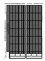
115
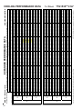
COOLING OPERATION
Design Subcooling, 10 °F + 3 @ the liquid access fitting connection AHRI 95 test conditions. Design Superheat 10 °F + 3 @ the compressor suction access fitting connection.
Outdoor Ambient Temperature
65
75
85
95
105
Entering Indoor Wet Bulb Temperature
IDB* Airflow
59
63
67
71
59
63
67
71
59
63
67
71
59
63
67
71
59
63
67
71
59
MBh
23.5 24.0 25.7 27.5 23.0 23.5 25.1 26.8 22.4
22.9
24.5 26.2 21.9
22.4
23.9
25.5 20.8 21.2 22.7 24.3 19.3
S/T
1.00 0.92 0.75 0.56 1.00 0.95 0.77 0.58 1.00
1.00
0.79 0.59 1.00
1.00
0.82
0.61 1.00 1.00 0.85 0.63 1.00
Delta T 23
21
19
15
22
22
19
15
22
22
19
15
21
22
19
15
20
21
19
15
19
951
KW
1.53 1.56 1.61 1.66 1.65 1.68 1.74 1.80 1.75
1.79
1.85 1.91 1.85
1.89
1.95
2.01 1.92 1.97 2.03 2.10 1.99
AMPS 7.1
7.3
7.5
7.7
7.6
7.8
8.0
8.2
8.2
8.3
8.6
8.8
8.6
8.8
9.1
9.4
9.1
9.3
9.6
9.9
9.6
HI PR 231
249
263
274
259
279
295
307
295
317
335
350
336
362
382
398
378
407
430
448
418
LO PR 111
119
129
138
118
125
137
146
122
130
142
151
129
137
149
159
135
143
156
167
139
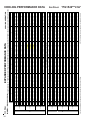
COOLING PERFORMANCE DATA
*PG1524***41A*
EXPANDED PERFORMANCE DATA
25.9
0.70
19
1.79
8.7
217
101
29.4
0.87
21
1.86
9.0
228
106
28.5
0.83
22
1.85
9.0
226
105
26.3
0.80
22
1.80
8.8
219
102
MBh
S/T
Delta T
KW
AMPS
HI PR
LO PR
MBh
S/T
Delta T
KW
AMPS
HI PR
LO PR
MBh
S/T
Delta T
KW
AMPS
HI PR
LO PR
MBh
S/T
Delta T
KW
AMPS
HI PR
LO PR
1000
875
1125
875
1000
29.4
0.74
20
1.89
9.1
243
112
27.1
0.71
20
1.84
9.0
236
109
30.3
0.78
19
1.90
9.2
245
113
26.8
0.59
17
1.83
8.9
233
108
29.1
0.61
16
1.87
9.1
240
111
30.0
0.64
16
1.89
9.1
243
112
31.8
0.56
16
1.95
9.4
257
122
29.4
0.54
17
1.90
9.2
249
119
32.8
0.59
16
1.96
9.4
259
124
29.4
0.41
13
1.88
9.1
246
118
31.9
0.42
12
1.93
9.3
254
121
32.8
0.44
12
1.94
9.4
256
122
34.1
0.36
11
2.01
9.6
268
130
31.5
0.35
12
1.96
9.4
260
126
35.2
0.38
11
2.02
9.7
270
132
-
-
-
27.9
0.86
22
1.99
9.5
253
111
25.7
0.83
22
1.94
9.3
246
108
28.7
0.90
21
2.00
9.6
256
112
25.3
0.73
19
1.92
9.3
243
107
27.4
0.76
19
1.97
9.5
251
110
28.2
0.79
18
1.99
9.5
253
111
28.7
0.77
20
2.03
9.7
273
118
26.5
0.74
21
1.98
9.5
264
115
29.6
0.81
19
2.05
9.8
275
120
26.2
0.61
17
1.97
9.4
262
114
28.4
0.63
16
2.01
9.6
270
117
29.3
0.66
16
2.03
9.7
273
118
31.1
0.58
17
2.10
10.0
288
129
28.7
0.56
17
2.04
9.8
279
125
32.0
0.61
16
2.11
10.0
291
131
28.7
0.42
13
2.03
9.7
276
124
31.1
0.44
13
2.08
9.9
285
128
32.1
0.46
12
2.09
10.0
288
129
33.3
0.37
11
2.16
10.3
300
138
30.8
0.36
12
2.11
10.0
291
134
34.3
0.39
11
2.18
10.3
303
139
-
-
-
27.2
0.88
22
2.11
10.2
288
116
25.1
0.85
22
2.06
10.0
279
112
28.0
0.92
21
2.13
10.3
291
117
24.7
0.75
19
2.04
9.9
277
111
26.8
0.78
19
2.09
10.1
285
115
27.6
0.81
18
2.11
10.2
288
116
28.0
0.79
20
2.16
10.4
310
123
25.9
0.76
21
2.11
10.2
301
119
28.9
0.83
19
2.18
10.5
313
124
25.6
0.62
17
2.09
10.1
298
118
27.7
0.65
17
2.14
10.3
307
122
28.6
0.68
16
2.16
10.4
310
123
30.3
0.60
17
2.23
10.7
327
134
28.0
0.58
17
2.17
10.4
318
130
31.2
0.63
16
2.25
10.7
331
136
28.0
0.43
13
2.15
10.3
314
129
30.4
0.45
13
2.21
10.6
324
133
31.3
0.47
12
2.23
10.7
327
134
* Entering Indoor Dry Bulb Temperature
NOTE: Shaded area is ACCA (TVA) conditions
High and low pressures are measured at the liquid and suction access fittings.
75
70
28.1
0.73
19
1.83
8.9
223
104
MBh
S/T
Delta T
KW
AMPS
HI PR
LO PR
1125
28.9
0.76
18
1.85
9.0
226
105
MBh
S/T
Delta T
KW
AMPS
HI PR
LO PR
32.6
0.38
11
2.30
11.0
341
143
30.0
0.37
12
2.24
10.7
331
139
33.5
0.40
11
2.32
11.1
345
145
-
-
-
26.6
0.91
22
2.22
10.7
328
122
24.5
0.88
23
2.17
10.5
318
118
27.3
0.95
21
2.24
10.8
331
123
24.1
0.77
20
2.15
10.4
315
117
26.1
0.80
19
2.20
10.7
325
120
26.9
0.84
18
2.22
10.7
328
122
27.3
0.81
20
2.27
11.0
353
129
25.2
0.78
21
2.21
10.7
343
125
28.2
0.85
20
2.29
11.0
357
131
25.0
0.64
17
2.20
10.6
339
124
27.1
0.67
17
2.25
10.9
350
128
27.9
0.70
16
2.27
11.0
353
129
29.6
0.62
17
2.34
11.2
373
141
27.3
0.59
17
2.29
11.0
362
137
30.5
0.65
16
2.36
11.3
377
143
27.4
0.45
13
2.27
10.9
358
136
29.6
0.46
13
2.32
11.2
369
140
30.5
0.49
12
2.34
11.2
373
141
25.2
0.94
22
2.31
11.3
369
127
23.3
0.91
22
2.26
11.0
358
124
26.0
0.99
21
2.33
11.4
373
129
22.9
0.80
19
2.24
11.0
354
122
24.8
0.83
19
2.30
11.2
365
126
25.5
0.87
18
2.31
11.3
369
127
26.0
0.84
20
2.37
11.5
397
136
24.0
0.81
21
2.31
11.3
385
132
26.7
0.89
19
2.39
11.6
401
137
23.7
0.67
17
2.29
11.2
381
130
25.7
0.69
16
2.35
11.4
393
134
26.5
0.73
16
2.37
11.5
397
136
28.1
0.64
17
2.44
11.8
419
148
25.9
0.62
17
2.38
11.6
407
144
29.0
0.67
16
2.46
11.9
424
149
26.0
0.46
13
2.36
11.5
403
142
28.2
0.48
12
2.42
11.8
415
147
29.0
0.50
12
2.44
11.8
419
148
30.2
0.41
11
2.53
12.2
438
158
27.8
0.40
12
2.46
11.9
424
153
31.1
0.43
11
2.55
12.3
442
159
-
-
-
71
59
23.4
0.95
20
2.39
11.8
408
132
21.6
0.92
21
2.34
11.6
396
128
24.1
1.00
20
2.41
11.9
412
133
21.2
0.81
18
2.32
11.5
392
127
23.0
0.84
18
2.37
11.8
404
130
23.7
0.88
17
2.39
11.8
408
132
63
24.1
0.85
19
2.45
12.1
439
140
22.2
0.82
19
2.39
11.8
426
136
24.8
0.89
18
2.47
12.2
443
142
22.0
0.67
16
2.37
11.7
421
135
23.8
0.70
15
2.43
12.0
434
139
24.5
0.73
15
2.45
12.1
439
140
67
26.0
0.64
15
2.53
12.4
463
153
24.0
0.62
16
2.47
12.1
450
148
26.8
0.68
15
2.55
12.5
468
155
24.1
0.47
12
2.44
12.0
445
147
26.1
0.48
12
2.51
12.3
459
152
26.9
0.51
11
2.53
12.4
463
153
115
27.9
0.41
11
2.61
12.8
483
163
25.8
0.40
11
2.55
12.5
469
158
28.8
0.43
10
2.64
12.9
488
165
-
-
-
71
COOLING OPERATION
KW = Total system power
AMPS: Unit amps (com p.+ evaporator + condenser fan motors)
31.8
0.40
12
2.42
11.6
389
150
29.3
0.38
12
2.36
11.3
377
146
32.7
0.42
11
2.44
11.7
393
152
-
-
-
Design Subcooling, 7 °F @ the liquid access fitting connection AHRI 95 test conditions. Design Superheat 5°F @ the compressor suction access fitting connection.
Outdoor Ambient Temperature
65
75
85
95
105
Entering Indoor Wet Bulb Temperature
59
63
67
71
59
63
67
71
59
63
67
71
59
63
67
71
59
63
67
IDB* Airflow
MODEL: *PG153009041A*
COOLING PERFORMANCE DATA
*PG1530***41A*
17
18
MODEL: *PG153009041A*
EXPANDED PERFORMANCE DATA
26.8
0.88
25
1.82
8.9
221
103
30.4
1.00
25
1.89
9.2
233
109
29.6
0.95
26
1.88
9.1
230
108
27.3
0.92
26
1.83
8.9
223
104
MBh
S/T
Delta T
KW
AMPS
HI PR
LO PR
MBh
S/T
Delta T
KW
AMPS
HI PR
LO PR
MBh
S/T
Delta T
KW
AMPS
HI PR
LO PR
MBh
S/T
Delta T
KW
AMPS
HI PR
LO PR
1000
875
1125
1000
875
27.8
0.89
26
1.87
9.1
240
111
30.1
0.92
25
1.92
9.3
248
114
31.0
0.96
24
1.93
9.3
250
116
27.4
0.82
24
1.86
9.0
238
110
29.7
0.85
23
1.90
9.2
245
113
29.1
0.80
24
1.93
9.3
254
121
31.6
0.83
24
1.98
9.5
262
125
32.5
0.87
23
1.99
9.6
264
126
29.3
0.67
21
1.91
9.2
251
120
31.7
0.69
20
1.96
9.4
259
124
31.1
0.65
21
1.99
9.6
265
129
33.7
0.67
21
2.04
9.8
273
133
34.7
0.71
20
2.06
9.9
276
134
31.3
0.50
16
1.97
9.5
262
128
33.9
0.52
16
2.02
9.7
270
132
26.6
0.95
27
1.97
9.5
251
110
28.9
0.99
26
2.02
9.7
258
114
29.7
1.00
24
2.04
9.7
261
115
26.2
0.91
25
1.96
9.4
248
109
28.4
0.94
25
2.00
9.6
256
113
27.2
0.92
26
2.01
9.6
270
117
29.4
0.95
26
2.06
9.9
278
121
30.3
1.00
25
2.08
9.9
281
122
26.8
0.85
24
2.00
9.6
267
116
29.0
0.88
24
2.05
9.8
275
120
28.4
0.83
25
2.08
9.9
285
128
30.8
0.86
24
2.13
10.1
294
132
31.7
0.90
23
2.15
10.2
297
133
28.6
0.69
21
2.06
9.8
282
127
31.0
0.72
20
2.11
10.0
291
131
30.3
0.67
21
2.14
10.2
297
136
32.9
0.70
21
2.20
10.4
306
141
33.9
0.73
20
2.22
10.5
309
142
30.6
0.52
17
2.13
10.1
294
135
33.1
0.54
16
2.18
10.3
303
139
26.0
0.98
27
2.09
10.1
285
115
28.2
1.00
26
2.15
10.3
294
118
29.0
1.00
24
2.16
10.4
297
119
25.6
0.93
25
2.08
10.0
282
113
27.7
0.97
25
2.13
10.3
291
117
26.5
0.94
26
2.14
10.3
307
122
28.7
0.98
26
2.19
10.5
316
126
29.6
1.00
24
2.21
10.6
319
127
26.1
0.87
24
2.12
10.2
304
121
NOTE:
28.3
0.91
24
2.18
10.5
313
124
32.3
0.55
16
2.32
11.1
345
145
27.0
1.00
25
2.24
10.8
331
123
27.6
0.94
24
2.29
11.0
357
131
29.5
0.76
21
2.36
11.3
377
143
31.5
0.57
16
2.44
11.7
393
152
27.8
0.85
25
2.21
10.6
324
133
30.1
0.88
24
2.26
10.8
334
137
31.0
0.92
23
2.28
10.9
337
139
29.6
0.69
21
2.28
10.9
338
142
32.1
0.72
21
2.34
11.1
348
146
33.1
0.75
20
2.36
11.2
352
148
25.4
1.00
27
2.20
10.7
325
120
27.5
1.00
25
2.26
10.9
335
124
28.3
1.00
23
2.28
11.0
338
125
25.9
0.97
26
2.25
10.9
349
128
28.0
1.00
26
2.31
11.1
360
132
28.9
1.00
24
2.33
11.2
364
133
27.1
0.88
25
2.32
11.2
369
140
29.4
0.91
25
2.38
11.4
380
144
30.2
0.95
24
2.40
11.5
384
146
24.1
1.00
25
2.29
11.2
365
126
26.1
1.00
24
2.35
11.5
377
130
26.9
1.00
22
2.37
11.6
380
131
23.7
1.00
25
2.28
11.1
362
125
25.7
1.00
24
2.33
11.4
373
129
24.6
1.00
26
2.35
11.4
393
134
26.6
1.00
24
2.41
11.7
405
138
27.4
1.00
22
2.43
11.8
409
140
24.2
0.94
24
2.33
11.3
389
133
26.2
0.97
23
2.39
11.6
401
137
25.7
0.91
25
2.42
11.7
415
146
27.9
0.95
24
2.48
12.0
428
151
28.7
0.99
23
2.51
12.1
432
153
25.9
0.76
21
2.40
11.7
411
145
28.0
0.79
20
2.46
11.9
424
149
27.5
0.74
21
2.50
12.1
433
156
29.7
0.77
21
2.57
12.4
446
161
30.6
0.80
20
2.59
12.5
451
162
27.7
0.57
17
2.48
12.0
429
154
30.0
0.59
16
2.55
12.3
442
159
71
30.9
0.62
16
2.57
12.4
446
161
22.3
1.00
23
2.37
11.8
404
130
24.2
1.00
22
2.44
12.0
416
134
24.9
1.00
20
2.46
12.1
420
136
21.9
1.01
23
2.35
11.7
400
129
23.8
1.00
22
2.42
11.9
412
133
59
24.5
1.00
20
2.44
12.0
416
134
22.8
1.00
24
2.43
12.0
434
139
24.7
1.00
23
2.49
12.3
448
143
25.4
1.00
21
2.51
12.4
452
144
22.4
0.94
22
2.41
11.9
430
137
24.3
0.98
22
2.47
12.2
443
142
63
25.0
1.00
20
2.49
12.3
448
143
23.8
0.92
23
2.51
12.3
459
151
25.8
0.95
23
2.57
12.6
473
156
26.6
1.00
22
2.59
12.7
478
158
24.0
0.77
19
2.49
12.2
454
150
26.0
0.80
19
2.55
12.5
468
155
67
26.7
0.84
18
2.57
12.6
473
156
115
25.4
0.75
20
2.59
12.7
478
161
27.6
0.77
20
2.66
13.0
493
166
28.4
0.81
19
2.68
13.1
498
168
25.6
0.57
15
2.57
12.6
474
160
27.8
0.60
15
2.64
12.9
488
165
71
28.6
0.62
15
2.66
13.0
493
166
COOLING OPERATION
KW = Total system power
AMPS: Unit amps (comp.+ evaporator + condenser fan motors)
28.9
0.71
22
2.40
11.5
385
149
31.3
0.74
21
2.46
11.8
397
153
32.3
0.77
20
2.48
11.9
401
155
27.9 29.8 24.9
25.5
27.2
29.1
0.71 0.53 0.96
0.90
0.73
0.55
21
17
25
24
21
17
2.19 2.26 2.18
2.23
2.31
2.38
10.5 10.8 10.6
10.8
11.1
11.4
321
335
322
346
365
381
132
140
119
127
138
147
Shaded area reflects AHRI rating conditions
30.2
0.74
21
2.25
10.7
331
136
* Entering Indoor Dry Bulb Temperature
NOTE: Shaded area is AHRI Rating Conditions
High and low pressures are measured at the liquid and suction access fittings.
85
80
29.0
0.91
24
1.86
9.0
228
106
MBh
S/T
Delta T
KW
AMPS
HI PR
LO PR
Design Subcooling, 7 °F @ the liquid access fitting connection AHRI 95 test conditions. Design Superheat 5°F @ the compressor suction access fitting connection.
Outdoor Ambient Temperature
65
75
85
95
105
Entering Indoor Wet Bulb Temperature
IDB* Airflow
59
63
67
71
59
63
67
71
59
63
67
71
59
63
67
71
59
63
67
MBh
29.9 30.6 32.7 34.9 29.2 29.9 31.9 34.1 28.5
29.2
31.1 33.3 27.8
28.4
30.4
32.5 26.4 27.0 28.9
S/T
0.95 0.89 0.73 0.54 1.00 0.93 0.75 0.56 1.00
0.95
0.77 0.58 1.00
1.00
0.80
0.60 1.00 1.00 0.83
Delta T 23
22
19
16
24
23
20
16
23
23
20
16
23
23
20
16
22
22
20
1125
KW
1.88 1.92 1.98 2.04 2.02 2.06 2.13 2.20 2.15
2.19
2.26 2.34 2.26
2.31
2.38
2.46 2.35 2.41 2.48
AMPS 9.1
9.3
9.5
9.8
9.7
9.9
10.1 10.4 10.3
10.5
10.8 11.1 10.9
11.1
11.4
11.8 11.5 11.7 12.0
HI PR 230
248
262
273
258
278
294
306
294
316
334
348
335
360
380
397
377
405
428
LO PR 108
114
125
133
114
121
132
141
118
126
137
146
124
132
144
153
130
138
151
COOLING PERFORMANCE DATA
*PG1530***41A*
MODEL: *PG1536***41A*
EXPANDED PERFORMANCE DATA
24.1
0.61
17
1.62
7.3
240
116
22.2
0.59
17
1.58
7.1
233
113
25.0
0.78
20
1.64
7.4
245
119
24.3
0.74
21
1.63
7.3
242
118
MBh
23.2
S/T
0.73
Delta T 19
KW
1.58
AMPS
7.1
HI PR 223
LO PR 109
MBh
21.4
S/T
0.70
Delta T 20
KW
1.55
AMPS
7.0
HI PR 216
LO PR 106
MBh
24.3
S/T
0.87
Delta T 22
KW
1.61
AMPS
7.2
HI PR 227
LO PR 112
MBh
23.6
S/T
0.83
Delta T 22
KW
1.60
AMPS
7.2
HI PR 225
LO PR 111
800
700
900
26.3
0.56
17
1.68
7.5
256
128
27.1
0.59
16
1.69
7.6
258
130
24.3
0.41
13
1.63
7.3
246
123
26.4
0.42
13
1.66
7.5
253
127
67
27.2
0.44
12
1.68
7.5
256
128
28.2
0.36
12
1.73
7.8
267
137
29.1
0.38
11
1.74
7.8
270
138
-
-
71
-
23.1
0.86
23
1.71
7.7
253
117
23.7
0.90
22
1.73
7.7
255
118
20.9
0.73
20
1.66
7.4
243
112
22.7
0.75
20
1.70
7.6
250
116
59
23.4
0.79
19
1.71
7.7
253
117
23.7
0.77
21
1.75
7.8
272
124
24.5
0.80
20
1.76
7.9
275
126
21.7
0.61
17
1.70
7.6
261
119
23.5
0.63
17
1.74
7.8
269
123
63
24.2
0.66
16
1.75
7.8
272
124
25.7
0.58
17
1.80
8.1
287
136
26.5
0.61
16
1.82
8.1
290
137
23.8
0.42
13
1.75
7.8
276
130
25.7
0.44
13
1.79
8.0
284
134
67
26.5
0.46
12
1.80
8.1
287
136
27.6
0.37
12
1.86
8.3
299
145
28.4
0.39
11
1.88
8.4
302
146
-
-
71
-
22.5
0.88
23
1.82
8.2
287
121
23.2
0.92
22
1.83
8.3
290
123
20.4
0.75
20
1.76
8.0
276
117
22.1
0.77
20
1.80
8.2
284
120
59
22.8
0.81
19
1.82
8.2
287
121
23.2
0.79
21
1.86
8.4
309
129
23.9
0.82
20
1.87
8.5
312
130
21.2
0.62
17
1.80
8.1
297
124
22.9
0.65
17
1.84
8.3
306
128
25.1
0.60
17
1.92
8.7
326
141
25.8
0.62
16
1.93
8.7
330
142
23.2
0.43
13
1.86
8.4
314
135
25.1
0.45
13
1.90
8.6
323
140
24.8
0.37
12
1.93
8.7
330
146
26.9
0.38
12
1.98
8.9
341
150
27.7
0.40
11
2.00
9.0
344
152
-
-
20.3
0.88
23
1.87
8.5
317
124
22.0
0.91
23
1.91
8.7
327
128
22.6
0.95
22
1.93
8.8
331
129
19.9
0.77
20
1.85
8.4
314
122
21.6
0.80
20
1.90
8.7
324
126
23.3
0.85
20
1.97
9.0
356
137
22.6
0.81
21
1.95
8.9
352
136
20.9
0.78
21
1.91
8.7
342
132
20.7
0.64
17
1.89
8.6
338
130
22.4
0.67
17
1.94
8.8
349
134
Outdoor Ambient Temperature
85
95
Entering Indoor Wet Bulb Temperature
63
67
71
59
63
23.6
25.9
22.2
23.1
0.68
0.47
0.84
0.70
16
12
19
16
1.86
1.92
1.91
1.95
8.4
8.7
8.7
8.9
309
326
327
352
129
141
128
136
MBh
21.8 22.4 24.3 26.1 21.3 21.9 23.7 25.5 20.8
21.4
23.2
S/T
0.80 0.71 0.54 0.35 0.83 0.74 0.56 0.36 0.85
0.76
0.57
Delta T 23
21
17
12
23
21
17
12
23
21
17
700
KW
1.56 1.59 1.64 1.69 1.67 1.71 1.76 1.82 1.78
1.81
1.87
AMPS
7.0
7.2
7.4
7.6
7.5
7.7
7.9
8.1
8.0
8.2
8.4
HI PR 218
235
248
259
245
264
278
290
279
300
317
LO PR 107
114
125
133
113
121
132
140
118
125
137
* Entering Indoor Dry Bulb Temperature
NOTE: Shaded area is ACCA (TVA) conditions
High and low pressures are measured at the liquid and suction access fittings.
800
900
63
24.8
0.64
16
1.63
7.3
242
118
59
MBh
23.9
S/T
0.76
Delta T 19
KW
1.59
AMPS
7.2
HI PR 225
LO PR 111
Airflow
75
22.6
0.59
18
1.97
8.9
361
144
24.5
0.61
17
2.02
9.2
372
148
25.2
0.64
17
2.03
9.2
376
150
22.6
0.45
13
1.95
8.9
357
142
24.5
0.46
13
2.00
9.1
368
147
67
25.3
0.48
13
2.02
9.2
372
148
20.9
0.94
23
1.99
9.2
368
134
21.5
0.99
22
2.01
9.3
372
135
18.9
0.80
20
1.93
8.9
353
128
20.5
0.83
20
1.97
9.1
364
132
59
21.1
0.87
19
1.99
9.2
368
134
21.5
0.84
21
2.03
9.4
396
142
22.1
0.88
20
2.05
9.5
400
144
19.6
0.67
17
1.97
9.1
380
137
21.3
0.69
17
2.02
9.3
392
141
63
21.9
0.73
16
2.03
9.4
396
142
23.2
0.64
17
2.10
9.7
418
155
23.9
0.67
16
2.12
9.8
423
157
21.5
0.46
13
2.03
9.4
402
149
23.3
0.48
13
2.08
9.6
414
154
67
24.0
0.50
12
2.10
9.7
418
155
25.0
0.41
12
2.17
10.0
436
165
25.7
0.43
11
2.19
10.1
441
167
-
-
71
-
19.3
0.95
21
2.06
9.7
407
138
19.9
1.00
20
2.08
9.8
411
140
17.5
0.81
19
1.99
9.4
391
133
19.0
0.84
18
2.04
9.6
403
137
59
19.6
0.88
18
2.06
9.7
407
138
19.9
0.85
19
2.10
9.9
438
147
20.5
0.89
19
2.12
10.0
442
149
18.2
0.67
16
2.04
9.6
420
141
19.7
0.70
16
2.09
9.8
433
146
63
20.3
0.73
15
2.10
9.9
438
147
21.5
0.64
16
2.17
10.2
462
161
22.2
0.67
15
2.19
10.3
467
162
19.9
0.47
12
2.10
9.9
444
154
21.6
0.48
12
2.15
10.1
458
159
67
22.2
0.51
12
2.17
10.2
462
161
23.1
0.41
11
2.25
10.5
482
171
23.8
0.43
11
2.26
10.6
487
173
-
-
71
-
24.2 19.3 19.8 21.5 23.0 17.8 18.4 19.9 21.3
0.38 0.91 0.81 0.62 0.40 0.92 0.82 0.62 0.40
12
23
21
17
12
21
20
16
11
2.03 1.94 1.98 2.05 2.12 2.01 2.05 2.12 2.19
9.2
9.0
9.2
9.4
9.8
9.5
9.7
9.9
10.3
376
357
384
406
423
395
425
448
468
153
130
138
151
160
134
143
156
166
KW = Total system power
AMPS: Unit amps (comp.+ evaporator + condenser fan motors)
26.3
0.40
12
2.08
9.5
388
158
27.1
0.41
11
2.10
9.5
392
159
-
-
71
-
105
1ST STAGE
75
70
IDB*
65
115
COOLING OPERATION
Design Subcooling, 15°F + 3 @ the liquid access fitting connection AHRI 95 test conditions. Design Superheat 9°F + 3 @ the compressor suction access fitting connection.
COOLING PERFORMANCE DATA
*PG1536***41A*
19
20
MODEL: *PG1536***41A*
EXPANDED PERFORMANCE DATA
25.7
0.96
25
1.67
7.5
250
121
24.9
0.92
26
1.65
7.4
247
120
23.0
0.89
27
1.61
7.3
240
116
MBh
25.2
S/T
1.00
Delta T 26
KW
1.63
AMPS
7.4
HI PR 232
LO PR 114
MBh
24.4
S/T
0.95
Delta T 27
KW
1.62
AMPS
7.3
HI PR 230
LO PR 113
MBh
22.6
S/T
0.92
Delta T 27
KW
1.58
AMPS
7.1
HI PR 223
LO PR 109
700
900
800
700
24.1
0.80
25
1.66
7.5
253
127
26.1
0.83
25
1.70
7.7
261
131
26.9
0.87
24
1.72
7.7
264
132
24.2
0.67
21
1.65
7.4
251
126
25.7
0.65
22
1.72
7.7
264
135
27.8
0.67
22
1.76
7.9
272
140
28.7
0.70
21
1.77
8.0
275
141
25.9
0.50
17
1.70
7.7
261
134
28.0
0.52
17
1.74
7.8
270
138
22.0
0.95
28
1.70
7.6
250
116
23.9
0.99
27
1.74
7.8
258
119
24.6
1.00
25
1.76
7.9
260
120
21.7
0.91
26
1.69
7.6
248
114
23.5
0.94
25
1.73
7.7
255
118
22.5
0.92
27
1.74
7.8
269
123
24.3
0.95
27
1.78
8.0
277
127
25.1
1.00
26
1.79
8.0
280
128
22.1
0.85
25
1.72
7.7
266
122
24.0
0.88
24
1.76
7.9
275
126
23.5
0.83
26
1.79
8.0
284
134
25.5
0.86
25
1.83
8.2
293
138
26.3
0.90
24
1.85
8.2
296
140
23.6
0.69
22
1.78
7.9
281
133
25.6
0.72
21
1.82
8.1
290
137
25.1
0.67
22
1.85
8.2
296
143
27.2
0.70
22
1.89
8.4
305
147
28.0
0.73
21
1.91
8.5
309
149
25.3
0.52
17
1.83
8.2
293
142
27.4
0.54
17
1.88
8.4
302
146
21.5
0.98
28
1.80
8.2
284
120
23.3
1.00
27
1.85
8.4
293
124
24.0
1.00
25
1.86
8.4
296
125
21.1
0.93
26
1.79
8.1
282
119
22.9
0.96
25
1.83
8.3
290
123
21.9
0.94
27
1.84
8.3
306
128
23.8
0.98
27
1.89
8.5
315
132
24.5
1.00
25
1.90
8.6
319
133
21.6
0.87
25
1.83
8.3
303
127
23.4
0.90
24
1.87
8.5
312
130
23.0
0.85
26
1.90
8.6
323
140
24.9
0.88
25
1.95
8.8
333
144
25.6
0.92
24
1.96
8.9
336
145
23.1
0.71
22
1.89
8.5
320
138
25.0
0.74
21
1.93
8.7
330
142
* Entering Indoor Dry Bulb Temperature
NOTE: Shaded area is AHRI Rating Conditions
High and low pressures are measured at the liquid and suction access fittings.
22.7
0.82
24
1.60
7.2
237
115
MBh
22.2
S/T
0.88
Delta T 25
KW
1.57
AMPS
7.1
HI PR 221
LO PR 108
800
26.2
0.69
21
1.69
7.6
258
130
24.5
0.69
22
1.96
8.9
337
149
26.5
0.71
22
2.01
9.1
347
153
27.3
0.75
21
2.03
9.2
351
155
24.7
0.53
17
1.95
8.8
334
147
26.7
0.55
17
2.00
9.0
344
152
21.0
1.00
28
1.90
8.7
324
126
22.7
1.00
26
1.94
8.9
334
130
23.4
1.00
24
1.96
8.9
337
131
20.6
0.96
26
1.88
8.6
321
125
22.4
1.00
26
1.93
8.8
331
129
21.4
0.97
27
1.94
8.8
348
134
23.2
1.00
27
1.99
9.1
359
138
23.9
1.00
24
2.00
9.1
363
140
21.1
0.90
25
1.92
8.8
345
133
22.8
0.93
25
1.97
9.0
356
137
22.4
0.88
26
2.00
9.1
368
147
24.3
0.91
25
2.05
9.3
379
151
25.0
0.95
24
2.07
9.4
383
153
22.5
0.73
22
1.98
9.0
364
145
24.4
0.76
21
2.03
9.2
376
150
19.9
1.00
26
1.97
9.1
364
132
21.6
1.00
25
2.02
9.4
376
136
22.3
1.00
23
2.04
9.4
379
138
19.6
1.00
26
1.96
9.1
361
131
21.2
1.00
24
2.01
9.3
372
135
20.3
1.00
27
2.02
9.3
392
141
22.0
1.00
25
2.07
9.6
404
145
22.7
1.00
23
2.09
9.6
408
147
20.0
0.93
25
2.00
9.3
388
139
21.7
0.97
24
2.05
9.5
400
144
21.3
0.91
25
2.08
9.6
414
154
23.1
0.94
25
2.14
9.8
427
158
23.8
0.99
24
2.15
9.9
431
160
21.4
0.76
21
2.07
9.5
410
152
23.2
0.79
21
2.12
9.8
423
157
22.7
0.74
22
2.15
9.9
432
164
24.6
0.77
22
2.21
10.2
445
169
25.3
0.80
21
2.22
10.3
450
170
22.9
0.57
17
2.13
9.8
428
162
24.8
0.59
17
2.19
10.1
441
167
18.5
1.00
24
2.04
9.6
403
137
20.0
1.00
23
2.09
9.9
415
141
20.6
1.00
21
2.11
9.9
419
142
18.2
1.00
24
2.03
9.5
399
135
19.7
1.00
23
2.08
9.8
411
140
18.8
1.00
25
2.09
9.8
433
146
20.4
1.00
23
2.14
10.1
447
150
21.0
1.00
21
2.16
10.1
451
152
18.6
0.94
23
2.07
9.7
429
144
20.1
0.98
23
2.12
10.0
442
149
19.7
0.92
24
2.15
10.1
457
159
21.4
0.95
23
2.21
10.4
472
164
22.0
1.00
22
2.23
10.5
476
165
19.8
0.77
20
2.14
10.0
453
157
21.5
0.80
20
2.19
10.3
467
162
67
22.1
0.83
19
2.21
10.4
472
164
21.0
0.74
21
2.23
10.5
477
169
22.8
0.77
20
2.28
10.7
492
174
23.5
0.81
19
2.30
10.8
497
176
21.2
0.57
16
2.21
10.4
472
168
23.0
0.59
16
2.26
10.6
487
173
71
23.6
0.62
15
2.28
10.7
492
174
KW = Total system power
AMPS: Unit amps (comp.+ evaporator + condenser fan motors)
23.9
0.71
22
2.06
9.4
384
156
25.9
0.74
22
2.12
9.6
396
161
26.7
0.77
21
2.13
9.7
400
163
24.1
0.55
17
2.05
9.3
380
155
26.1
0.57
17
2.10
9.5
392
159
63
20.7
1.00
21
2.14
10.1
447
150
1ST STAGE
85
80
24.6
0.85
24
1.64
7.4
245
119
MBh
24.0
S/T
0.91
Delta T 25
KW
1.61
AMPS
7.2
HI PR 227
LO PR 112
59
20.3
1.00
21
2.09
9.9
415
141
115
COOLING OPERATION
Design Subcooling, 15°F + 3 @ the liquid access fitting connection AHRI 95 test conditions. Design Superheat 9°F + 3 @ the compressor suction access fitting connection.
Outdoor Ambient Temperature
65
75
85
95
105
Entering Indoor Wet Bulb Temperature
IDB* Airflow
59
63
67
71
59
63
67
71
59
63
67
71
59
63
67
71
59
63
67
71
MBh
24.7 25.3 27.0 28.9 24.2 24.7 26.4 28.2 23.6
24.1
25.8 27.5 23.0
23.5
25.1 26.9 21.9 22.3 23.9 25.5
S/T
0.95 0.89 0.73 0.54 1.00 0.93 0.75 0.56 1.00
0.95
0.77 0.58 1.00
1.00
0.80 0.60 1.00 1.00 0.83 0.62
Delta T 24
23
20
16
25
23
20
16
24
23
20
16
24
24
20
16
22
23
20
16
900
KW
1.62 1.65 1.70 1.76 1.74 1.78 1.83 1.89 1.85
1.89
1.95 2.01 1.94
1.99
2.05 2.12 2.02 2.07 2.14 2.21
AMPS
7.3
7.4
7.7
7.9
7.8
8.0
8.2
8.4
8.4
8.5
8.8
9.1
8.9
9.1
9.3
9.6
9.4
9.6
9.8
10.2
HI PR 230
247
261
272
258
277
293
305
293
315
333
347
334
359
379
396
376
404
427
445
LO PR 113
120
131
140
119
127
138
147
124
132
144
153
130
138
151
161
136
145
158
169
COOLING PERFORMANCE DATA
*PG1536***41A*
MODEL: *PG1536***41A*
EXPANDED PERFORMANCE DATA
35.3
0.88
21
2.54
12.7
254
111
34.2
0.84
22
2.52
12.7
252
110
31.6
0.81
22
2.46
12.4
244
107
MBh
S/T
Delta T
KW
AMPS
HI PR
LO PR
MBh
S/T
Delta T
KW
AMPS
HI PR
LO PR
MBh
S/T
Delta T
KW
AMPS
HI PR
LO PR
1072
1378
1225
1072
32.5
0.72
20
2.52
12.6
263
114
35.3
0.75
20
2.58
12.9
271
117
36.3
0.79
19
2.60
13.0
274
118
32.2
0.59
16
2.50
12.5
260
112
35.2
0.55
17
2.59
12.9
278
124
38.2
0.57
16
2.65
13.2
286
128
39.3
0.60
16
2.68
13.3
289
129
35.3
0.41
12
2.57
12.8
275
123
38.2
0.43
12
2.63
13.1
283
127
37.8
0.35
11
2.67
13.3
289
132
41.0
0.37
11
2.74
13.6
298
136
42.2
0.38
11
2.76
13.7
301
137
-
-
30.9
0.84
22
2.65
13.2
274
113
33.5
0.87
22
2.71
13.4
283
116
34.5
0.91
21
2.73
13.5
285
117
30.4
0.74
19
2.63
13.1
271
112
32.9
0.76
19
2.69
13.3
280
115
31.8
0.75
20
2.70
13.4
295
120
34.4
0.78
20
2.77
13.7
304
124
35.5
0.81
19
2.79
13.8
307
125
31.5
0.62
17
2.68
13.3
292
119
34.1
0.64
16
2.75
13.6
301
122
34.4
0.57
17
2.79
13.7
311
131
37.3
0.59
16
2.86
14.0
321
135
38.4
0.62
16
2.88
14.1
324
136
34.5
0.43
13
2.77
13.6
308
130
37.4
0.44
12
2.83
13.9
318
134
36.9
0.36
12
2.88
14.1
325
140
40.0
0.38
11
2.95
14.4
335
144
41.2
0.40
11
2.97
14.5
338
145
-
-
30.1
0.86
22
2.81
14.0
312
117
32.7
0.89
22
2.88
14.3
321
121
33.6
0.93
21
2.90
14.4
325
122
29.6
0.76
19
2.79
13.9
309
116
32.1
0.78
19
2.86
14.2
318
120
31.0
0.77
20
2.87
14.3
335
125
33.6
0.80
20
2.94
14.6
346
129
34.6
0.84
19
2.97
14.7
349
130
30.7
0.63
17
2.85
14.2
332
123
33.3
0.65
16
2.92
14.5
342
127
33.6
0.58
17
2.96
14.6
354
136
36.4
0.60
16
3.04
15.0
365
140
37.5
0.63
16
3.06
15.1
369
142
33.7
0.44
13
2.94
14.5
351
135
36.5
0.45
12
3.01
14.9
361
139
* Entering Indoor Dry Bulb Temperature
NOTE: Shaded area is ACCA (TVA) conditions
High and low pressures are measured at the liquid and suction access fittings.
31.1
0.71
19
2.45
12.3
242
106
MBh
S/T
Delta T
KW
AMPS
HI PR
LO PR
1225
34.9
0.62
16
2.56
12.8
268
116
36.1
0.37
12
3.06
15.1
369
145
39.1
0.39
11
3.13
15.4
381
149
40.2
0.41
11
3.16
15.5
385
151
-
-
29.4
0.89
22
2.95
14.8
355
123
31.9
0.92
22
3.03
15.1
366
127
32.8
0.96
21
3.05
15.2
370
128
28.9
0.78
19
2.93
14.6
351
122
31.3
0.81
19
3.00
15.0
362
126
30.3
0.79
21
3.02
15.0
382
131
32.8
0.60
17
3.11
15.4
403
143
35.5
0.62
17
3.19
15.8
416
147
36.6
0.65
16
3.22
15.9
420
149
33.8
0.86
19
3.12
15.5
398
136
32.8
0.82
20
3.09
15.4
394
135
32.8
0.45
13
3.09
15.3
399
142
35.6
0.47
12
3.17
15.7
412
146
30.0
0.65
17
2.99
14.9
378
130
32.5
0.68
16
3.07
15.3
390
134
27.9
0.92
22
3.08
15.5
399
129
30.3
0.95
22
3.15
15.8
412
133
31.2
1.00
21
3.18
16.0
416
134
27.5
0.81
19
3.05
15.4
395
128
29.8
0.84
19
3.13
15.7
408
132
28.8
0.82
20
3.14
15.8
430
137
31.2
0.85
20
3.22
16.2
443
142
32.1
0.90
19
3.25
16.3
447
143
28.5
0.68
17
3.12
15.7
425
136
30.8
0.70
16
3.19
16.0
439
140
31.1
0.62
17
3.24
16.2
454
150
33.7
0.65
16
3.33
16.6
468
155
34.7
0.68
16
3.35
16.7
473
156
31.2
0.47
13
3.22
16.1
449
148
33.8
0.49
12
3.30
16.5
463
153
33.4
0.40
11
3.35
16.7
473
160
36.2
0.42
11
3.44
17.1
488
165
37.3
0.44
11
3.47
17.2
493
166
-
-
25.9
0.93
21
3.18
16.2
441
133
28.0
0.96
20
3.26
16.6
455
138
28.9
1.00
19
3.29
16.7
459
139
25.4
0.82
18
3.15
16.1
437
132
27.6
0.85
18
3.23
16.5
450
136
26.6
0.83
19
3.25
16.6
475
142
28.9
0.86
19
3.33
16.9
490
146
29.7
0.90
18
3.36
17.1
494
148
26.4
0.68
15
3.22
16.4
470
141
28.6
0.71
15
3.30
16.8
485
145
28.8
0.63
16
3.36
17.0
501
155
31.2
0.65
15
3.44
17.4
517
160
32.2
0.68
15
3.47
17.5
522
161
28.9
0.47
12
3.33
16.9
496
153
31.3
0.49
12
3.41
17.3
512
158
67
32.2
0.51
11
3.44
17.4
517
160
31.0
0.40
11
3.47
17.5
523
165
33.5
0.42
11
3.56
17.9
539
170
34.5
0.44
10
3.59
18.1
545
172
-
-
71
-
KW = Total system power
AMPS: Unit amps (comp.+ evaporator + condenser fan motors)
35.2
0.39
12
3.22
15.9
421
152
38.1
0.40
11
3.30
16.3
434
157
39.3
0.42
11
3.32
16.4
438
159
-
-
63
29.4
0.74
15
3.33
16.9
489
146
2ND STAGE
75
70
33.7
0.74
19
2.50
12.6
249
109
MBh
S/T
Delta T
KW
AMPS
HI PR
LO PR
59
28.4
0.89
17
3.26
16.6
455
138
115
COOLING OPERATION
Design Subcooling, 15°F + 3 @ the liquid access fitting connection AHRI 95 test conditions. Design Superheat 9°F + 3 @ the compressor suction access fitting connection.
Outdoor Ambient Temperature
65
75
85
95
105
Entering Indoor Wet Bulb Temperature
IDB* Airflow
59
63
67
71
59
63
67
71
59
63
67
71
59
63
67
71
59
63
67
71
MBh
34.7 36.0 39.4
33.9 35.1 38.5
33.1
34.3
37.6
32.3
33.4
36.6
30.7 31.8 34.8
S/T
0.77 0.65 0.45
0.80 0.67 0.46
0.82
0.69
0.48
0.85
0.71
0.49
0.88 0.74 0.51
Delta T 18
15
12
18
16
12
18
16
12
18
16
12
18
16
12
1378
KW
2.52 2.58 2.65
2.71 2.77 2.86
2.88
2.94
3.03
3.03
3.09
3.19
3.15 3.22 3.33
AMPS 12.7 12.9 13.2
13.4 13.7 14.0
14.3
14.6
15.0
15.1
15.4
15.8
15.8 16.2 16.6
HI PR 252
271
286
282
304
321
321
346
365
366
394
416
412
443
468
LO PR 110
117
128
116
124
135
121
129
140
127
135
147
133
142
154
-
COOLING PERFORMANCE DATA
*PG1536***41A*
21
22
MODEL: *PG1536***41A*
EXPANDED PERFORMANCE DATA
36.5
1.00
24
2.58
12.9
259
113
35.5
0.96
26
2.56
12.8
257
112
32.7
0.93
26
2.50
12.6
249
109
MBh
S/T
Delta T
KW
AMPS
HI PR
LO PR
MBh
S/T
Delta T
KW
AMPS
HI PR
LO PR
MBh
S/T
Delta T
KW
AMPS
HI PR
LO PR
1072
1378
1225
1072
33.4
0.90
26
2.55
12.8
268
116
36.2
0.93
25
2.62
13.1
276
119
37.2
0.98
24
2.64
13.2
279
121
32.9
0.83
23
2.53
12.7
265
115
34.9
0.81
24
2.63
13.1
283
126
37.9
0.84
24
2.70
13.4
292
130
39.0
0.88
23
2.72
13.5
295
132
35.1
0.68
20
2.61
13.0
280
125
38.1
0.70
20
2.68
13.3
289
129
37.3
0.66
21
2.72
13.5
295
135
40.4
0.68
21
2.78
13.8
304
139
41.6
0.71
20
2.80
13.9
308
140
37.5
0.51
16
2.69
13.4
292
133
40.7
0.52
16
2.76
13.7
301
138
32.0
0.96
26
2.69
13.3
280
115
34.6
1.00
26
2.76
13.6
288
119
35.7
1.00
24
2.78
13.7
291
120
31.4
0.92
25
2.67
13.2
277
114
34.0
0.95
24
2.73
13.5
285
117
32.6
0.93
26
2.75
13.6
301
122
35.3
0.96
26
2.81
13.9
310
126
36.4
1.00
24
2.84
14.0
313
127
32.1
0.86
24
2.73
13.5
298
121
34.8
0.89
23
2.79
13.8
307
125
34.1
0.84
25
2.83
13.9
318
134
37.0
0.87
24
2.90
14.2
328
138
38.1
0.91
23
2.93
14.3
331
139
34.3
0.70
21
2.81
13.8
315
132
37.2
0.73
20
2.88
14.1
324
136
36.4
0.68
21
2.92
14.3
331
142
39.5
0.71
21
3.00
14.6
342
147
40.6
0.74
20
3.02
14.7
345
148
36.7
0.52
16
2.90
14.2
328
141
39.7
0.54
16
2.97
14.5
338
145
31.2
0.99
26
2.86
14.2
318
120
33.8
1.00
25
2.93
14.5
328
123
34.8
1.00
23
2.95
14.6
331
125
30.7
0.94
25
2.83
14.1
315
118
33.2
0.98
24
2.90
14.4
325
122
31.8
0.95
26
2.92
14.5
342
127
34.5
0.99
26
2.99
14.8
353
131
35.5
1.00
24
3.01
14.9
356
132
31.3
0.88
24
2.89
14.4
339
126
34.0
0.92
23
2.97
14.7
349
130
33.3
0.86
25
3.01
14.9
361
139
36.1
0.89
24
3.08
15.2
373
143
37.2
0.94
23
3.11
15.3
376
145
33.5
0.72
21
2.99
14.7
358
138
36.3
0.75
20
3.06
15.1
369
142
* Entering Indoor Dry Bulb Temperature
NOTE: Shaded area is AHRI Rating Conditions
High and low pressures are measured at the liquid and suction access fittings.
32.2
0.89
24
2.48
12.5
247
108
MBh
S/T
Delta T
KW
AMPS
HI PR
LO PR
1225
35.6
0.86
23
2.60
13.0
274
118
35.6
0.70
21
3.11
15.3
377
148
38.5
0.72
21
3.19
15.6
389
152
39.7
0.76
20
3.21
15.8
392
154
35.8
0.54
17
3.08
15.2
373
146
38.8
0.56
16
3.16
15.5
385
151
30.5
1.00
26
3.00
15.0
362
126
33.0
1.00
25
3.08
15.3
373
130
34.0
1.00
23
3.10
15.4
377
131
29.9
0.97
25
2.98
14.9
359
124
32.4
1.00
24
3.05
15.2
370
128
31.0
0.98
26
3.07
15.3
390
134
33.6
1.00
25
3.14
15.6
402
138
34.6
1.00
23
3.17
15.7
406
139
30.6
0.91
24
3.04
15.1
386
132
33.1
0.95
24
3.12
15.5
398
136
32.5
0.89
25
3.17
15.7
412
146
35.2
0.92
24
3.25
16.0
424
150
36.3
0.97
23
3.27
16.1
429
152
32.7
0.74
21
3.14
15.5
407
144
35.4
0.77
20
3.22
15.9
420
149
28.9
1.00
25
3.13
15.7
407
132
31.3
1.00
24
3.20
16.1
420
136
32.3
1.00
22
3.23
16.2
424
137
28.4
1.01
25
3.10
15.6
403
130
30.8
1.00
23
3.18
16.0
416
134
29.5
1.00
25
3.19
16.0
438
140
31.9
1.00
24
3.28
16.4
452
144
32.9
1.00
22
3.30
16.5
457
146
29.1
0.95
24
3.17
15.9
434
139
31.5
0.98
23
3.25
16.3
448
143
30.9
0.92
24
3.30
16.5
463
153
33.5
0.96
24
3.38
16.8
477
158
34.5
1.00
23
3.41
17.0
482
159
31.0
0.77
21
3.27
16.3
458
151
33.6
0.80
20
3.35
16.7
473
156
33.0
0.75
21
3.41
17.0
483
163
35.7
0.78
21
3.49
17.4
498
168
36.8
0.81
20
3.52
17.5
503
170
33.2
0.58
16
3.38
16.8
478
161
36.0
0.60
16
3.47
17.2
493
166
26.8
1.00
23
3.23
16.5
450
136
29.0
1.00
22
3.32
16.9
464
140
29.9
1.00
20
3.34
17.0
469
142
26.3
1.02
23
3.21
16.4
446
135
28.5
1.00
21
3.29
16.7
460
139
27.3
1.00
23
3.30
16.8
484
145
29.6
1.00
22
3.39
17.2
499
149
30.5
1.00
20
3.42
17.3
504
151
26.9
0.95
22
3.28
16.7
480
143
29.2
0.99
22
3.36
17.1
494
148
28.6
0.93
23
3.41
17.3
512
158
31.0
0.96
22
3.50
17.7
527
163
31.9
1.00
21
3.53
17.8
533
165
28.8
0.78
19
3.38
17.1
506
157
31.2
0.81
19
3.47
17.5
522
161
67
32.1
0.84
18
3.50
17.7
527
163
30.5
0.75
20
3.53
17.8
534
168
33.1
0.78
19
3.62
18.2
550
174
34.1
0.82
19
3.65
18.4
556
175
30.7
0.58
15
3.50
17.7
528
167
33.3
0.60
15
3.59
18.1
545
172
71
34.3
0.63
14
3.62
18.2
550
174
KW = Total system power
AMPS: Unit amps (comp.+ evaporator + condenser fan motors)
34.7
0.72
21
3.27
16.1
429
155
37.6
0.75
21
3.35
16.5
443
160
38.7
0.78
20
3.38
16.6
447
162
34.9
0.55
17
3.24
16.0
425
154
37.8
0.58
16
3.33
16.4
438
159
63
30.0
1.00
20
3.39
17.2
499
149
2ND STAGE
85
80
34.9
0.92
24
2.54
12.7
254
111
MBh
S/T
Delta T
KW
AMPS
HI PR
LO PR
59
29.4
1.00
20
3.32
16.9
464
140
115
COOLING OPERATION
Design Subcooling, 15°F + 3 @ the liquid access fitting connection AHRI 95 test conditions. Design Superheat 9°F + 3 @ the compressor suction access fitting connection.
Outdoor Ambient Temperature
65
75
85
95
105
Entering Indoor Wet Bulb Temperature
IDB* Airflow
59
63
67
71
59
63
67
71
59
63
67
71
59
63
67
71
59
63
67
71
MBh
35.9 36.7 39.2 41.9 35.1 35.8 38.3 40.9 34.2
35.0
37.4 40.0 33.4
34.1
36.5
39.0 31.7 32.4 34.6 37.0
S/T
0.96 0.90 0.74 0.55 1.00 0.94 0.76 0.57 1.00
0.96
0.78 0.58 1.00
1.00
0.81
0.60 1.00 1.00 0.84 0.63
Delta T 23
22
19
15
23
22
19
16
23
22
20
16
22
23
20
16
21
22
19
15
1378
KW
2.56 2.62 2.70 2.78 2.76 2.81 2.90 3.00 2.93
2.99
3.08 3.19 3.08
3.14
3.25
3.35 3.20 3.28 3.38 3.49
AMPS 12.8 13.1 13.4 13.8 13.6 13.9 14.2 14.6 14.5
14.8
15.2 15.6 15.3
15.6
16.0
16.5 16.1 16.4 16.8 17.4
HI PR 257
276
292
304
288
310
328
342
328
353
373
389
373
402
424
443
420
452
477
498
LO PR 112
119
130
139
119
126
138
147
123
131
143
152
130
138
150
160
136
144
158
168
COOLING PERFORMANCE DATA
*PG1536***41A*
EXPANDED PERFORMANCE DATA
31.4
0.67
22
2.23
10.7
228
101
35.0
0.80
23
2.31
11.0
238
106
34.6
0.79
24
2.30
11.0
237
105
32.0
0.76
26
2.24
10.8
230
102
MBh
S/T
Delta T
KW
AMPS
HI PR
LO PR
MBh
S/T
Delta T
KW
AMPS
HI PR
LO PR
MBh
S/T
Delta T
KW
AMPS
HI PR
LO PR
MBh
S/T
Delta T
KW
AMPS
HI PR
LO PR
1055
875
1125
875
1055
35.7
0.71
22
2.35
11.2
255
112
32.9
0.68
24
2.29
11.0
247
109
36.0
0.72
21
2.36
11.3
256
112
32.6
0.56
19
2.27
10.9
245
107
35.3
0.58
18
2.33
11.2
253
111
35.7
0.59
17
2.34
11.2
253
111
38.6
0.53
18
2.43
11.5
269
122
35.6
0.51
19
2.37
11.3
261
119
39.0
0.54
17
2.43
11.6
270
123
35.7
0.39
15
2.35
11.2
259
117
38.7
0.40
14
2.41
11.5
267
121
39.1
0.41
13
2.41
11.5
267
121
41.4
0.34
12
2.51
11.9
281
130
38.2
0.33
13
2.44
11.6
273
126
41.8
0.35
12
2.51
11.9
282
131
-
-
-
33.8
0.82
24
2.48
11.8
266
111
31.2
0.79
26
2.42
11.5
258
108
34.2
0.83
23
2.49
11.8
267
111
30.7
0.69
22
2.40
11.4
255
107
33.3
0.72
21
2.46
11.7
263
110
33.6
0.73
20
2.47
11.7
264
110
34.8
0.73
22
2.54
12.0
286
118
32.2
0.71
24
2.47
11.7
278
115
35.2
0.75
21
2.54
12.0
287
119
31.8
0.58
19
2.45
11.6
275
114
34.5
0.60
18
2.51
11.9
283
117
34.8
0.61
17
2.52
11.9
284
117
37.7
0.55
18
2.62
12.3
302
129
34.8
0.53
20
2.55
12.0
293
125
38.1
0.56
18
2.63
12.4
303
129
34.9
0.40
15
2.53
11.9
290
124
37.8
0.42
14
2.60
12.2
299
128
38.2
0.42
13
2.60
12.3
300
128
40.5
0.36
13
2.71
12.7
315
137
37.3
0.34
13
2.64
12.4
306
133
40.9
0.36
12
2.71
12.7
316
138
-
-
-
33.0
0.84
24
2.64
12.6
303
116
30.5
0.81
26
2.57
12.3
293
112
33.4
0.85
23
2.65
12.6
303
116
30.0
0.71
22
2.55
12.2
290
111
32.5
0.74
21
2.62
12.5
299
114
32.8
0.75
20
2.63
12.5
300
115
34.0
0.75
22
2.70
12.9
326
123
31.4
0.72
24
2.63
12.6
316
119
34.3
0.76
21
2.71
12.9
327
123
31.1
0.59
19
2.61
12.5
313
118
33.7
0.62
18
2.68
12.8
322
122
34.0
0.63
17
2.68
12.8
323
122
36.8
0.57
18
2.79
13.2
344
134
34.0
0.55
20
2.72
12.9
333
130
37.2
0.58
18
2.80
13.3
345
135
34.0
0.41
15
2.70
12.8
330
129
36.9
0.43
14
2.77
13.1
340
133
37.2
0.44
13
2.77
13.2
341
133
* Entering Indoor Dry Bulb Temperature
NOTE: Shaded area is ACCA (TVA) conditions
High and low pressures are measured at the liquid and suction access fittings.
75
70
34.1
0.69
21
2.28
10.9
235
104
MBh
S/T
Delta T
KW
AMPS
HI PR
LO PR
1125
34.4
0.71
20
2.29
11.0
235
104
MBh
S/T
Delta T
KW
AMPS
HI PR
LO PR
39.5
0.37
13
2.88
13.7
359
143
36.5
0.35
13
2.81
13.3
348
139
39.9
0.37
12
2.89
13.7
360
143
-
-
-
32.2
0.87
24
2.78
13.3
345
121
29.7
0.83
26
2.71
13.0
334
118
32.5
0.88
23
2.79
13.4
346
122
29.2
0.73
23
2.69
12.9
331
117
31.7
0.76
21
2.76
13.2
341
120
32.0
0.78
20
2.77
13.3
342
120
33.2
0.77
22
2.85
13.6
371
129
30.6
0.75
24
2.77
13.3
360
125
33.5
0.79
22
2.85
13.7
372
129
30.3
0.61
20
2.75
13.2
356
124
32.8
0.64
18
2.82
13.5
367
128
33.2
0.65
18
2.83
13.5
368
128
35.9
0.59
18
2.94
14.0
392
141
33.1
0.56
20
2.87
13.7
380
137
36.3
0.60
18
2.95
14.0
393
141
33.2
0.42
15
2.84
13.6
376
135
36.0
0.44
14
2.92
13.9
388
140
36.3
0.45
13
2.92
13.9
389
140
30.6
0.90
24
2.90
14.1
388
127
28.3
0.87
26
2.83
13.7
376
123
30.9
0.92
23
2.91
14.1
389
128
27.8
0.76
22
2.80
13.6
372
122
30.1
0.79
21
2.88
14.0
384
126
30.4
0.81
20
2.88
14.0
385
126
31.5
0.80
22
2.97
14.4
417
135
29.1
0.77
24
2.89
14.0
405
131
31.8
0.82
21
2.98
14.4
418
136
28.8
0.64
19
2.87
13.9
401
130
31.2
0.66
18
2.94
14.3
413
134
31.5
0.67
17
2.95
14.3
414
134
34.1
0.61
18
3.07
14.8
440
148
31.5
0.59
19
2.99
14.4
427
143
34.5
0.62
17
3.08
14.8
442
148
31.5
0.44
15
2.96
14.3
423
142
34.2
0.46
14
3.04
14.7
436
146
34.5
0.47
13
3.05
14.7
437
147
36.6
0.39
12
3.17
15.3
459
157
33.8
0.38
13
3.09
14.9
446
153
37.0
0.40
12
3.18
15.3
461
158
-
-
-
71
59
28.4
0.91
22
3.01
14.8
428
132
26.2
0.87
24
2.93
14.4
415
128
28.6
0.92
22
3.01
14.8
430
132
25.7
0.77
21
2.90
14.3
411
126
27.9
0.80
19
2.98
14.7
424
130
28.2
0.81
19
2.99
14.7
425
131
63
29.2
0.81
21
3.07
15.1
461
140
26.9
0.78
22
3.00
14.8
447
136
29.5
0.83
20
3.08
15.2
462
140
26.7
0.64
18
2.97
14.6
443
134
28.9
0.67
17
3.05
15.0
456
139
29.2
0.68
16
3.06
15.0
458
139
67
31.6
0.61
17
3.18
15.6
487
153
29.2
0.59
18
3.10
15.2
472
148
31.9
0.63
16
3.19
15.6
488
153
29.2
0.44
14
3.07
15.1
467
147
31.7
0.46
13
3.15
15.4
482
151
32.0
0.47
12
3.16
15.5
483
152
115
33.9
0.39
12
3.29
16.1
508
163
31.3
0.38
13
3.20
15.7
492
158
34.3
0.40
11
3.30
16.1
509
163
-
-
-
71
COOLING OPERATION
KW = Total system power
AMPS: Unit amps (comp.+ evaporator + condenser fan motors)
38.5
0.38
13
3.04
14.5
408
150
35.6
0.36
14
2.96
14.1
396
146
38.9
0.38
12
3.05
14.5
410
151
-
-
-
Design Subcooling,10 °F @ the liquid access fitting connection AHRI 95 test conditions. Design Superheat 6°F @ the compressor suction access fitting connection.
Outdoor Ambient Temperature
65
75
85
95
105
Entering Indoor Wet Bulb Temperature
59
63
67
71
59
63
67
71
59
63
67
71
59
63
67
71
59
63
67
IDB* Airflow
MODEL: *PG153709041A*
COOLING PERFORMANCE DATA
*PG1537***41A*
23
24
MODEL: *PG153709041A*
EXPANDED PERFORMANCE DATA
32.5
0.83
29
2.26
10.9
232
103
36.2
0.93
27
2.34
11.2
243
108
35.9
0.91
28
2.34
11.2
242
107
33.1
0.87
30
2.28
10.9
235
104
MBh
S/T
Delta T
KW
AMPS
HI PR
LO PR
MBh
S/T
Delta T
KW
AMPS
HI PR
LO PR
MBh
S/T
Delta T
KW
AMPS
HI PR
LO PR
MBh
S/T
Delta T
KW
AMPS
HI PR
LO PR
1055
875
1125
1055
875
33.7
0.84
30
2.33
11.1
252
111
36.6
0.88
28
2.39
11.4
260
114
36.9
0.89
27
2.39
11.4
261
115
33.2
0.78
27
2.31
11.1
250
110
36.0
0.81
25
2.37
11.3
258
113
35.3
0.76
28
2.40
11.5
267
121
38.3
0.79
26
2.47
11.7
275
125
38.7
0.81
25
2.47
11.7
276
125
35.5
0.64
24
2.39
11.4
264
120
38.5
0.66
22
2.45
11.6
272
123
37.7
0.62
24
2.48
11.8
278
129
40.9
0.64
23
2.55
12.1
287
133
41.3
0.65
22
2.55
12.1
288
133
38.0
0.48
19
2.46
11.7
275
127
41.1
0.49
18
2.53
12.0
284
131
32.3
0.91
31
2.46
11.7
263
110
35.0
0.94
29
2.52
11.9
271
113
35.4
0.96
28
2.53
12.0
272
114
31.8
0.86
29
2.44
11.6
261
109
34.4
0.90
27
2.50
11.8
269
112
33.0
0.87
30
2.51
11.9
283
117
35.7
0.91
28
2.58
12.2
292
121
36.1
0.93
27
2.58
12.2
293
121
32.5
0.81
28
2.49
11.8
280
116
35.2
0.84
26
2.56
12.1
289
119
34.5
0.79
29
2.60
12.2
299
128
37.4
0.82
27
2.66
12.5
308
132
37.8
0.83
26
2.67
12.5
309
132
34.7
0.66
24
2.57
12.1
296
126
37.6
0.68
22
2.64
12.4
305
130
36.8
0.64
25
2.68
12.6
312
136
39.9
0.66
23
2.75
12.9
322
140
40.3
0.68
22
2.76
12.9
323
141
37.1
0.49
19
2.66
12.5
309
135
40.2
0.51
18
2.73
12.8
318
139
31.6
0.93
31
2.62
12.5
299
114
34.2
0.96
29
2.69
12.8
309
118
34.5
0.98
28
2.69
12.8
310
118
31.0
0.89
29
2.60
12.4
296
113
33.6
0.92
27
2.66
12.7
306
117
32.2
0.90
30
2.68
12.8
322
122
34.9
0.93
28
2.75
13.1
332
125
35.2
0.95
27
2.75
13.1
333
126
31.7
0.83
28
2.65
12.7
319
120
NOTE:
34.3
0.86
26
2.72
13.0
329
124
39.2
0.52
18
2.91
13.8
362
144
32.8
0.95
27
2.81
13.4
348
123
33.5
0.89
26
2.87
13.7
375
130
35.8
0.72
23
2.97
14.1
396
142
38.3
0.54
18
3.07
14.6
413
152
33.7
0.81
29
2.77
13.1
340
133
36.5
0.84
27
2.84
13.4
351
137
36.9
0.86
26
2.84
13.5
352
137
36.0
0.66
25
2.86
13.5
355
141
39.0
0.68
23
2.93
13.9
366
146
39.3
0.69
22
2.94
13.9
367
146
30.8
0.96
31
2.76
13.2
341
120
33.4
1.00
29
2.83
13.6
352
124
33.7
1.00
28
2.84
13.6
353
124
31.4
0.93
31
2.82
13.5
367
128
34.0
0.96
28
2.89
13.8
378
132
34.4
0.98
27
2.90
13.9
379
132
32.9
0.84
29
2.91
13.9
387
139
35.6
0.87
27
2.99
14.2
399
144
36.0
0.88
26
3.00
14.3
401
144
29.3
1.00
31
2.88
14.0
384
126
31.7
1.00
28
2.95
14.3
395
130
32.0
1.00
26
2.96
14.3
397
130
28.8
0.95
29
2.85
13.8
380
125
31.2
0.99
27
2.93
14.2
392
128
29.8
0.96
30
2.94
14.3
413
134
32.3
1.00
28
3.02
14.6
426
138
32.6
1.00
27
3.03
14.6
427
138
29.4
0.89
28
2.92
14.1
409
133
31.8
0.92
26
2.99
14.5
421
137
31.2
0.87
28
3.04
14.7
436
146
33.8
0.90
27
3.12
15.0
449
151
34.2
0.92
26
3.13
15.1
451
151
31.4
0.73
24
3.02
14.6
432
145
34.0
0.75
22
3.10
14.9
445
149
33.3
0.70
25
3.15
15.2
455
156
36.1
0.73
23
3.23
15.5
469
160
36.5
0.74
22
3.24
15.6
470
161
33.6
0.54
19
3.12
15.0
450
154
36.4
0.56
18
3.20
15.4
464
159
71
36.7
0.57
17
3.21
15.4
465
159
27.1
1.00
28
2.98
14.7
424
130
29.4
1.00
26
3.06
15.0
437
134
29.7
1.00
24
3.07
15.1
438
135
26.6
0.96
27
2.95
14.6
420
129
28.9
0.99
25
3.03
14.9
433
133
59
29.1
1.00
24
3.04
15.0
434
133
27.6
0.97
28
3.05
15.0
456
138
29.9
1.00
26
3.13
15.4
470
143
30.2
1.00
25
3.14
15.4
472
143
27.2
0.90
26
3.02
14.9
452
137
29.5
0.93
24
3.10
15.2
466
141
63
29.8
0.95
23
3.11
15.3
467
142
28.9
0.87
27
3.15
15.4
482
151
31.3
0.91
25
3.23
15.8
497
156
31.7
0.92
24
3.24
15.9
498
156
29.1
0.73
22
3.12
15.3
477
150
31.5
0.76
21
3.21
15.7
492
154
67
31.8
0.77
20
3.22
15.7
493
155
115
30.9
0.71
23
3.26
15.9
502
161
33.4
0.74
21
3.35
16.4
518
166
33.8
0.75
21
3.36
16.4
519
166
31.1
0.55
18
3.23
15.8
497
159
33.7
0.57
17
3.32
16.2
513
164
71
34.0
0.58
16
3.33
16.3
514
165
COOLING OPERATION
KW = Total system power
AMPS: Unit amps (comp.+ evaporator + condenser fan motors)
35.1
0.68
25
3.01
14.3
404
149
38.0
0.70
23
3.09
14.7
417
153
38.4
0.72
22
3.10
14.7
418
154
33.9 36.2 30.3
30.9
33.0
35.3
0.68 0.51 0.92
0.86
0.70
0.52
24
19
29
28
24
19
2.74 2.83 2.73
2.80
2.89
2.99
13.0 13.4 13.1
13.4
13.8
14.2
337
351
338
363
384
400
131
140
119
126
138
147
Shaded area reflects AHRI rating conditions
36.7
0.70
22
2.81
13.3
347
136
* Entering Indoor Dry Bulb Temperature
NOTE: Shaded area is AHRI Rating Conditions
High and low pressures are measured at the liquid and suction access fittings.
85
80
35.3
0.87
27
2.32
11.1
239
106
MBh
S/T
Delta T
KW
AMPS
HI PR
LO PR
Design Subcooling,10 °F @ the liquid access fitting connection AHRI 95 test conditions. Design Superheat 6°F @ the compressor suction access fitting connection.
Outdoor Ambient Temperature
65
75
85
95
105
Entering Indoor Wet Bulb Temperature
IDB* Airflow
59
63
67
71
59
63
67
71
59
63
67
71
59
63
67
71
59
63
67
MBh
35.6 36.4 38.9 41.6 34.8 35.5 38.0 40.6 33.9
34.7
37.1 39.6 33.1
33.8
36.2
38.7 31.5 32.2 34.4
S/T
0.88 0.83 0.67 0.50 0.91 0.86 0.70 0.52 0.94
0.88
0.72 0.53 0.97
0.91
0.74
0.55 1.00 0.94 0.77
Delta T 26
25
21
17
26
25
22
17
26
25
22
17
26
25
22
17
26
25
22
1125
KW
2.32 2.37 2.45 2.53 2.51 2.56 2.65 2.74 2.67
2.73
2.82 2.92 2.81
2.88
2.97
3.08 2.93 3.00 3.10
AMPS 11.1 11.3 11.7 12.0 11.9 12.1 12.4 12.8 12.7
13.0
13.4 13.8 13.5
13.8
14.2
14.6 14.2 14.5 15.0
HI PR 240
258
273
285
269
290
306
319
306
330
348
363
349
376
397
414
393
423
446
LO PR 107
113
124
132
113
120
131
139
117
125
136
145
123
131
143
152
129
137
150
COOLING PERFORMANCE DATA
*PG1537***41A*
EXPANDED PERFORMANCE DATA
35.6
0.69
21
2.50
11.0
217
107
40.4
0.85
23
2.60
11.4
228
113
39.2
0.81
24
2.58
11.3
226
112
36.2
0.78
25
2.52
11.1
219
108
MBh
S/T
Delta T
KW
AMPS
HI PR
LO PR
MBh
S/T
Delta T
KW
AMPS
HI PR
LO PR
MBh
S/T
Delta T
KW
AMPS
HI PR
LO PR
MBh
S/T
Delta T
KW
AMPS
HI PR
LO PR
1200
1050
1350
1050
1200
40.3
0.72
22
2.63
11.6
243
119
37.2
0.70
23
2.57
11.3
236
115
41.6
0.76
21
2.65
11.7
245
120
36.9
0.57
18
2.55
11.2
233
114
39.9
0.59
18
2.61
11.5
241
118
41.1
0.62
17
2.63
11.6
243
119
43.7
0.55
18
2.71
11.9
257
130
40.3
0.53
19
2.65
11.6
249
126
45.0
0.57
18
2.73
12.0
259
131
40.4
0.40
14
2.63
11.5
246
125
43.8
0.41
14
2.69
11.8
254
129
45.1
0.43
13
2.71
11.9
257
130
46.9
0.35
13
2.80
12.3
268
138
43.3
0.34
13
2.73
12.0
260
134
48.3
0.37
12
2.82
12.4
270
140
-
-
-
38.3
0.84
25
2.77
12.1
253
118
35.3
0.81
25
2.71
11.8
246
115
39.4
0.88
24
2.79
12.2
256
119
34.7
0.71
22
2.68
11.8
243
113
37.6
0.74
21
2.75
12.0
251
117
38.8
0.77
20
2.77
12.1
253
118
39.4
0.75
23
2.83
12.4
273
126
36.4
0.72
23
2.76
12.1
265
122
40.6
0.79
22
2.85
12.5
275
127
36.0
0.59
19
2.74
12.0
262
121
39.0
0.62
18
2.81
12.3
270
124
40.2
0.65
18
2.83
12.4
273
126
42.7
0.57
19
2.92
12.8
288
137
39.4
0.55
19
2.85
12.5
279
133
43.9
0.59
18
2.94
12.9
291
139
39.4
0.41
14
2.83
12.4
276
132
42.7
0.43
14
2.90
12.7
285
136
44.0
0.45
13
2.92
12.8
288
137
45.8
0.36
13
3.01
13.2
300
146
42.3
0.35
13
2.94
12.9
291
142
47.2
0.38
12
3.04
13.3
303
148
-
-
-
37.4
0.86
25
2.94
13.1
288
123
34.5
0.83
25
2.87
12.8
280
119
38.5
0.90
24
2.97
13.2
291
124
33.9
0.73
22
2.85
12.7
277
118
36.7
0.76
21
2.92
13.0
285
122
37.8
0.79
20
2.94
13.1
288
123
38.5
0.77
23
3.01
13.4
310
131
35.5
0.74
23
2.93
13.0
301
127
39.6
0.81
22
3.03
13.5
313
132
35.1
0.61
19
2.91
12.9
298
125
38.1
0.63
18
2.98
13.3
307
129
39.2
0.66
18
3.01
13.4
310
131
41.6
0.58
19
3.10
13.8
327
143
38.4
0.56
19
3.03
13.4
318
138
42.9
0.61
18
3.13
13.9
331
144
38.5
0.42
14
3.00
13.3
314
137
41.7
0.44
14
3.08
13.7
324
141
43.0
0.46
13
3.10
13.8
327
143
* Entering Indoor Dry Bulb Temperature
NOTE: Shaded area is ACCA (TVA) conditions
High and low pressures are measured at the liquid and suction access fittings.
75
70
38.5
0.71
21
2.56
11.2
224
111
MBh
S/T
Delta T
KW
AMPS
HI PR
LO PR
1350
39.7
0.75
20
2.58
11.3
226
112
MBh
S/T
Delta T
KW
AMPS
HI PR
LO PR
44.7
0.37
13
3.20
14.2
342
152
41.2
0.36
13
3.12
13.9
331
147
46.0
0.39
12
3.23
14.4
345
153
-
-
-
36.5
0.89
25
3.09
13.9
328
129
33.6
0.85
25
3.02
13.5
318
125
37.5
0.93
24
3.12
14.0
332
130
33.1
0.75
22
2.99
13.4
315
124
35.8
0.78
21
3.07
13.8
325
128
36.9
0.82
21
3.09
13.9
328
129
37.5
0.79
23
3.16
14.2
353
137
34.6
0.76
23
3.08
13.8
343
133
38.7
0.83
22
3.19
14.3
357
139
34.3
0.63
19
3.06
13.7
339
132
37.1
0.65
19
3.14
14.1
350
136
38.3
0.68
18
3.16
14.2
353
137
40.6
0.60
19
3.26
14.6
373
150
37.5
0.58
19
3.18
14.3
362
145
41.8
0.63
18
3.29
14.8
377
151
37.6
0.44
14
3.16
14.1
358
144
40.7
0.45
14
3.24
14.5
369
148
41.9
0.47
14
3.26
14.6
373
150
34.6
0.92
24
3.22
14.7
369
135
32.0
0.89
25
3.14
14.3
358
131
35.7
0.96
23
3.25
14.8
373
137
31.4
0.78
21
3.12
14.2
355
130
34.1
0.81
21
3.20
14.6
366
134
35.1
0.85
20
3.22
14.7
369
135
35.7
0.82
22
3.29
15.0
397
144
32.9
0.79
23
3.21
14.6
385
140
36.7
0.86
22
3.32
15.2
401
145
32.6
0.65
19
3.19
14.5
382
138
35.3
0.68
18
3.27
14.9
393
142
36.4
0.71
18
3.29
15.0
397
144
38.6
0.62
18
3.40
15.5
420
157
35.6
0.60
19
3.32
15.1
407
152
39.7
0.65
18
3.43
15.6
424
159
35.7
0.45
14
3.29
15.0
403
151
38.7
0.47
14
3.37
15.4
415
155
39.8
0.49
13
3.40
15.5
420
157
41.4
0.40
13
3.51
16.0
438
167
38.2
0.39
13
3.43
15.6
425
162
42.7
0.42
12
3.54
16.2
442
169
-
-
-
71
59
32.1
0.93
23
3.33
15.5
408
140
29.6
0.89
23
3.25
15.1
396
136
33.0
0.97
22
3.36
15.6
412
141
29.1
0.79
20
3.22
15.0
392
134
31.5
0.82
20
3.31
15.4
404
138
32.5
0.86
19
3.33
15.5
408
140
63
33.0
0.83
21
3.41
15.9
439
149
30.5
0.80
21
3.32
15.4
426
144
34.0
0.87
20
3.44
16.0
443
150
30.2
0.66
17
3.29
15.3
422
143
32.7
0.68
17
3.38
15.7
435
147
33.7
0.71
16
3.41
15.8
439
149
67
35.7
0.63
17
3.52
16.3
464
162
33.0
0.61
17
3.43
15.9
450
158
36.8
0.66
17
3.55
16.5
468
164
33.1
0.46
13
3.40
15.8
445
156
35.8
0.47
13
3.49
16.2
459
161
36.9
0.50
12
3.52
16.3
464
162
115
38.4
0.40
12
3.64
16.9
484
173
35.4
0.39
12
3.55
16.5
469
168
39.5
0.42
11
3.67
17.1
488
175
-
-
-
71
COOLING OPERATION
KW = Total system power
AMPS: Unit amps (comp.+ evaporator + condenser fan motors)
43.6
0.39
13
3.37
15.1
389
160
40.2
0.37
13
3.29
14.8
377
155
44.9
0.40
12
3.40
15.3
393
161
-
-
-
Design Subcooling,10 °F @ the liquid access fitting connection AHRI 95 test conditions. Design Superheat 6°F @ the compressor suction access fitting connection.
Outdoor Ambient Temperature
65
75
85
95
105
Entering Indoor Wet Bulb Temperature
59
63
67
71
59
63
67
71
59
63
67
71
59
63
67
71
59
63
67
IDB* Airflow
MODEL: *PG154211541A*
COOLING PERFORMANCE DATA
*PG1542***41A*
25
26
MODEL: *PG154211541A*
EXPANDED PERFORMANCE DATA
36.8
0.85
28
2.54
11.1
221
110
41.8
0.97
28
2.64
11.6
233
115
40.6
0.93
29
2.62
11.5
230
114
37.5
0.90
29
2.56
11.2
223
111
MBh
S/T
Delta T
KW
AMPS
HI PR
LO PR
MBh
S/T
Delta T
KW
AMPS
HI PR
LO PR
MBh
S/T
Delta T
KW
AMPS
HI PR
LO PR
MBh
S/T
Delta T
KW
AMPS
HI PR
LO PR
1200
1050
1350
1200
1050
38.2
0.86
29
2.61
11.5
240
118
41.4
0.90
28
2.67
11.8
248
121
42.6
0.94
27
2.69
11.9
250
123
37.6
0.80
26
2.59
11.4
238
117
40.8
0.83
26
2.65
11.7
245
120
40.0
0.78
27
2.69
11.8
254
129
43.3
0.81
27
2.76
12.1
262
133
44.6
0.85
26
2.78
12.2
264
134
40.2
0.65
23
2.67
11.7
251
127
43.5
0.68
23
2.73
12.0
259
131
42.7
0.63
24
2.77
12.2
265
137
46.2
0.66
23
2.84
12.5
273
141
47.6
0.69
22
2.87
12.6
276
143
43.0
0.49
18
2.75
12.1
262
136
46.5
0.51
18
2.82
12.4
270
140
36.6
0.93
30
2.75
12.0
251
117
39.6
0.96
29
2.82
12.3
259
121
40.8
1.00
28
2.84
12.4
261
122
36.0
0.89
28
2.73
11.9
248
116
39.0
0.92
27
2.79
12.2
256
119
37.3
0.90
29
2.81
12.3
270
124
40.4
0.93
29
2.88
12.6
278
128
41.6
0.97
28
2.90
12.7
281
130
36.7
0.83
27
2.78
12.2
267
123
39.8
0.86
26
2.85
12.5
275
127
39.1
0.81
28
2.89
12.7
285
136
42.3
0.84
27
2.97
13.0
294
140
43.6
0.88
26
2.99
13.1
297
141
39.3
0.68
23
2.87
12.6
282
134
42.5
0.70
23
2.94
12.9
291
139
41.7
0.66
24
2.99
13.1
297
145
45.1
0.68
24
3.06
13.4
306
149
46.5
0.71
23
3.09
13.5
309
151
42.0
0.51
19
2.96
13.0
294
143
45.5
0.52
18
3.04
13.3
303
148
35.7
0.95
30
2.92
13.0
285
122
38.7
0.99
29
2.99
13.3
294
125
39.9
1.00
27
3.02
13.4
297
127
35.1
0.91
28
2.90
12.9
282
120
38.0
0.94
27
2.97
13.2
291
124
36.4
0.92
29
2.98
13.3
307
129
39.4
0.95
29
3.06
13.6
316
133
40.6
1.00
28
3.08
13.7
320
135
35.9
0.85
27
2.96
13.1
304
128
NOTE:
38.9
0.88
26
3.03
13.5
313
132
44.4
0.54
18
3.23
14.4
345
153
37.1
0.97
28
3.12
14.0
332
130
37.9
0.91
26
3.19
14.3
357
139
40.5
0.74
23
3.29
14.8
377
151
43.3
0.55
18
3.40
15.3
393
161
38.1
0.83
28
3.08
13.6
324
141
41.3
0.86
27
3.15
14.0
334
146
42.5
0.90
26
3.18
14.1
337
147
40.7
0.67
24
3.18
14.1
338
150
44.1
0.70
24
3.26
14.5
348
155
45.4
0.73
23
3.28
14.6
352
157
34.8
0.98
30
3.07
13.8
325
128
37.7
1.00
29
3.15
14.1
335
132
38.9
1.00
26
3.17
14.2
338
133
35.5
0.95
29
3.13
14.1
350
136
38.5
0.98
29
3.21
14.4
360
140
39.6
1.00
27
3.24
14.6
364
141
37.2
0.86
28
3.24
14.5
369
148
40.3
0.89
27
3.32
14.9
381
153
41.5
0.93
26
3.35
15.0
384
154
33.1
1.00
29
3.20
14.6
365
134
35.9
1.00
27
3.28
15.0
377
138
36.9
1.00
25
3.30
15.1
380
139
32.5
0.97
28
3.17
14.5
362
132
35.2
1.00
27
3.25
14.8
373
137
33.7
0.98
29
3.27
14.9
393
142
36.6
1.00
28
3.35
15.3
405
147
37.6
1.00
26
3.38
15.4
409
148
33.2
0.91
27
3.24
14.8
389
141
36.0
0.95
26
3.32
15.2
401
145
35.3
0.89
27
3.37
15.4
415
155
38.3
0.92
27
3.46
15.8
428
160
39.4
0.97
26
3.49
15.9
432
162
35.5
0.74
23
3.34
15.2
411
154
38.5
0.77
23
3.43
15.6
424
159
37.7
0.72
24
3.48
15.9
433
165
40.8
0.75
23
3.57
16.3
446
171
42.1
0.78
22
3.60
16.5
451
172
38.0
0.56
18
3.45
15.8
429
164
41.1
0.58
18
3.54
16.2
442
169
71
42.4
0.60
17
3.57
16.3
446
171
30.7
1.00
27
3.31
15.4
404
138
33.2
1.00
25
3.39
15.8
416
143
34.2
1.00
23
3.42
15.9
420
144
30.1
0.98
26
3.28
15.2
400
137
32.6
1.00
25
3.36
15.6
412
141
59
33.6
1.00
23
3.39
15.8
416
143
31.3
0.99
27
3.38
15.7
434
147
33.9
1.00
26
3.46
16.1
448
152
34.9
1.00
24
3.49
16.3
452
153
30.8
0.92
25
3.35
15.6
430
146
33.4
0.95
24
3.44
16.0
443
150
63
34.4
1.00
23
3.46
16.1
448
152
32.7
0.90
26
3.49
16.2
459
161
35.5
0.93
25
3.58
16.6
473
166
36.5
0.97
24
3.61
16.8
478
167
32.9
0.75
22
3.46
16.1
454
159
35.6
0.78
21
3.55
16.5
468
164
67
36.7
0.81
20
3.58
16.6
473
166
115
34.9
0.73
22
3.61
16.8
479
171
37.8
0.75
22
3.70
17.2
493
176
39.0
0.79
21
3.73
17.4
498
178
35.2
0.56
17
3.58
16.6
474
169
38.1
0.58
17
3.67
17.1
488
175
71
39.2
0.61
16
3.70
17.2
493
176
COOLING OPERATION
KW = Total system power
AMPS: Unit amps (comp.+ evaporator + condenser fan motors)
39.7
0.69
24
3.34
15.0
385
158
43.0
0.72
24
3.43
15.4
397
163
44.3
0.76
23
3.46
15.5
401
164
38.3 41.0 34.2
35.0
37.4
40.0
0.69 0.52 0.94
0.88
0.72
0.53
23
19
28
27
23
19
3.05 3.15 3.04
3.11
3.21
3.31
13.5 14.0 13.7
14.0
14.4
14.9
321
335
322
346
365
381
140
149
126
134
147
156
Shaded area reflects AHRI rating conditions
41.5
0.72
23
3.13
13.9
331
144
* Entering Indoor Dry Bulb Temperature
NOTE: Shaded area is AHRI Rating Conditions
High and low pressures are measured at the liquid and suction access fittings.
85
80
39.9
0.89
27
2.60
11.4
228
113
MBh
S/T
Delta T
KW
AMPS
HI PR
LO PR
Design Subcooling,10 °F @ the liquid access fitting connection AHRI 95 test conditions. Design Superheat 6°F @ the compressor suction access fitting connection.
Outdoor Ambient Temperature
65
75
85
95
105
Entering Indoor Wet Bulb Temperature
IDB* Airflow
59
63
67
71
59
63
67
71
59
63
67
71
59
63
67
71
59
63
67
MBh
41.1 42.0 44.8 47.9 40.1 41.0 43.8 46.8 39.2
40.0
42.8 45.7 38.2
39.0
41.7
44.6 36.3 37.1 39.6
S/T
0.93 0.87 0.71 0.53 0.96 0.90 0.74 0.55 1.00
0.93
0.75 0.56 1.00
0.96
0.78
0.58 1.00 1.00 0.81
Delta T 26
25
22
17
26
25
22
18
27
25
22
18
26
25
22
18
25
25
22
1350
KW
2.62 2.67 2.76 2.84 2.82 2.88 2.97 3.06 2.99
3.06
3.15 3.26 3.15
3.21
3.32
3.43 3.28 3.35 3.46
AMPS 11.5 11.8 12.1 12.5 12.3 12.6 13.0 13.4 13.3
13.6
14.0 14.5 14.1
14.4
14.9
15.4 15.0 15.3 15.8
HI PR 230
248
262
273
259
278
294
306
294
316
334
348
335
360
381
397
377
405
428
LO PR 114
121
133
141
121
128
140
149
125
133
146
155
132
140
153
163
138
147
160
COOLING PERFORMANCE DATA
*PG1542***41A*
EXPANDED PERFORMANCE DATA
30.7
0.71
21
2.24
10.1
214
108
34.9
0.88
23
2.33
10.5
225
114
33.9
0.84
24
2.31
10.4
223
112
31.3
0.81
24
2.26
10.2
216
109
MBh
S/T
Delta T
KW
AMPS
HI PR
LO PR
MBh
S/T
Delta T
KW
AMPS
HI PR
LO PR
MBh
S/T
Delta T
KW
AMPS
HI PR
LO PR
MBh
S/T
Delta T
KW
AMPS
HI PR
LO PR
1100
963
1238
1100
963
32.2
0.72
22
2.30
10.4
233
116
34.9
0.75
22
2.36
10.6
240
120
35.9
0.79
21
2.37
10.7
242
121
31.9
0.59
18
2.29
10.3
230
115
34.5
0.62
18
2.34
10.5
237
118
34.8
0.55
18
2.37
10.6
246
127
37.7
0.57
18
2.42
10.9
253
131
38.9
0.60
17
2.44
11.0
256
132
34.9
0.41
14
2.35
10.6
243
125
37.8
0.43
13
2.41
10.8
251
129
37.4
0.35
13
2.44
11.0
256
135
40.5
0.37
12
2.50
11.2
264
139
41.7
0.38
12
2.52
11.3
267
140
-
-
30.5
0.84
24
2.42
10.8
243
115
33.1
0.87
24
2.47
11.1
250
119
34.1
0.91
23
2.49
11.2
253
120
30.0
0.74
21
2.40
10.8
240
114
32.5
0.76
21
2.46
11.0
248
118
31.4
0.75
22
2.47
11.0
261
123
34.1
0.78
22
2.52
11.3
269
126
35.1
0.81
21
2.54
11.4
272
128
31.1
0.62
18
2.45
11.0
258
121
33.7
0.64
18
2.51
11.2
266
125
34.0
0.57
18
2.54
11.3
276
134
36.9
0.59
18
2.60
11.6
284
138
38.0
0.62
17
2.62
11.7
287
139
34.1
0.43
14
2.52
11.3
273
132
36.9
0.44
14
2.58
11.5
281
137
36.5
0.36
13
2.62
11.7
288
143
39.6
0.38
13
2.68
12.0
296
147
40.7
0.40
12
2.70
12.0
299
148
-
-
29.8
0.86
24
2.56
11.6
276
120
32.3
0.89
24
2.62
11.9
285
123
33.3
0.93
23
2.64
11.9
287
125
29.3
0.76
21
2.54
11.5
273
119
31.7
0.78
21
2.60
11.8
282
122
30.7
0.77
23
2.61
11.8
297
127
33.2
0.80
22
2.67
12.1
306
131
34.2
0.84
21
2.69
12.2
309
133
30.4
0.63
18
2.59
11.7
294
126
32.9
0.65
18
2.65
12.0
303
130
33.2
0.58
18
2.69
12.1
314
139
36.0
0.60
18
2.76
12.4
323
143
37.1
0.63
17
2.78
12.5
327
145
33.3
0.44
14
2.67
12.0
310
138
36.1
0.45
14
2.73
12.3
320
142
-
-
35.6
0.37
13
2.77
12.5
327
148
38.6
0.39
13
2.84
12.8
337
153
39.8
0.41
12
2.86
12.9
341
154
Entering Indoor Dry Bulb Temperature
NOTE: Shaded area is ACCA (TVA) conditions
High and low pressures are measured at the liquid and suction access fittings.
33.3
0.74
21
2.29
10.3
221
111
MBh
S/T
Delta T
KW
AMPS
HI PR
LO PR
29.1
0.89
25
2.68
12.2
314
126
31.5
0.92
24
2.75
12.5
324
130
32.4
0.96
23
2.77
12.6
327
131
28.6
0.78
21
2.66
12.1
311
125
31.0
0.81
21
2.73
12.4
321
128
29.9
0.79
23
2.74
12.5
338
134
32.4
0.60
19
2.82
12.8
357
146
35.1
0.62
18
2.89
13.1
368
151
36.2
0.65
18
2.92
13.2
372
152
33.4
0.86
21
2.83
12.9
352
139
32.4
0.82
22
2.81
12.8
349
138
32.5
0.45
14
2.80
12.7
354
145
35.2
0.47
14
2.87
13.0
365
149
29.6
0.65
18
2.72
12.4
335
132
32.1
0.68
18
2.78
12.7
345
137
27.6
0.92
24
2.79
12.9
354
132
29.9
0.95
24
2.86
13.2
365
136
30.8
1.00
23
2.88
13.3
368
137
27.2
0.81
21
2.77
12.8
350
131
29.4
0.84
21
2.84
13.1
361
135
28.4
0.82
22
2.85
13.1
381
140
30.8
0.85
22
2.92
13.5
392
145
31.7
0.90
21
2.94
13.6
396
146
28.2
0.68
18
2.83
13.0
377
139
30.5
0.70
18
2.89
13.4
388
143
30.8
0.62
18
2.94
13.5
402
153
33.3
0.65
18
3.01
13.8
414
158
34.4
0.68
17
3.03
13.9
418
159
30.8
0.47
14
2.91
13.4
398
152
33.4
0.49
14
2.99
13.7
410
156
33.0
0.40
13
3.03
13.9
419
163
35.8
0.42
12
3.11
14.3
432
168
36.9
0.44
12
3.13
14.4
436
170
-
-
25.6
0.93
23
2.88
13.5
391
136
27.7
0.96
22
2.95
13.8
403
141
28.6
1.00
21
2.98
14.0
407
142
25.2
0.82
20
2.86
13.4
387
135
27.3
0.85
19
2.93
13.7
399
139
26.3
0.83
21
2.94
13.8
420
145
28.5
0.86
21
3.01
14.1
433
150
29.4
0.90
20
3.04
14.2
438
151
26.1
0.68
17
2.92
13.7
416
144
28.3
0.71
17
2.99
14.0
429
148
28.5
0.63
17
3.03
14.2
444
158
30.9
0.65
17
3.11
14.5
458
163
31.8
0.68
16
3.14
14.7
462
165
28.6
0.47
13
3.01
14.1
439
157
31.0
0.49
13
3.08
14.4
453
162
30.6
0.40
12
3.13
14.7
463
169
33.2
0.42
12
3.21
15.0
477
174
34.2
0.44
11
3.24
15.1
482
176
-
-
KW = Total system power
AMPS: Unit amps (com p.+ evaporator + condenser fan motors)
34.8
0.39
13
2.91
13.2
373
156
37.7
0.40
13
2.98
13.5
384
160
38.8
0.42
12
3.01
13.7
388
162
-
-
71
-
COO LING O PERATION
Design Subcooling, 15°F + 3 @ the liquid access fitting connection AHRI 95 test conditions. Design Superheat 9°F + 3 @ the compressor suction access fitting connection.
Outdoor Ambient Temperature
65
75
85
95
105
115
Entering Indoor Wet Bulb Temperature
Airflow
59
63
67
71
59
63
67
71
59
63
67
71
59
63
67
71
59
63
67
71
59
63
67
MBh
34.3 35.5 38.9
33.5 34.7 38.0
32.7 33.9 37.1
31.9
33.1
36.2
30.3 31.4 34.4
28.1 29.1 31.9
S/T
0.77 0.65 0.45
0.80 0.67 0.46
0.82 0.69 0.48
0.85
0.71
0.49
0.88 0.74 0.51
0.89 0.74 0.51
Delta T
20
17
13
20
17
13
20
17
13
20
17
13
20
17
13
19
16
12
1238
KW
2.31 2.35 2.42
2.47 2.52 2.60
2.62 2.67 2.76
2.75
2.81
2.89
2.86 2.92 3.01
2.95 3.01 3.11
AMPS 10.4 10.6 10.9
11.1 11.3 11.6
11.9 12.1 12.4
12.5
12.8
13.1
13.2 13.5 13.8
13.8 14.1 14.5
HI PR 223
240
253
250
269
284
284
306
323
324
349
368
364
392
414
403
433
458
LO PR 112
120
131
119
126
138
123
131
143
130
138
151
136
145
158
141
150
163
MOD EL: *PG1548***41A*
COOLING PERFORMANCE DATA
1ST STAGE *PG1548***41A*
27
28
EXPANDED PERFORMANCE DATA
31.8
0.89
27
2.28
10.3
218
110
36.1
1.00
27
2.36
10.6
230
116
35.1
0.96
28
2.34
10.6
227
115
32.4
0.93
29
2.29
10.3
221
111
MBh
S/T
Delta T
KW
AMPS
HI PR
LO PR
MBh
S/T
Delta T
KW
AMPS
HI PR
LO PR
MBh
S/T
Delta T
KW
AMPS
HI PR
LO PR
MBh
S/T
Delta T
KW
AMPS
HI PR
LO PR
1100
963
1238
1100
963
33.0
0.90
28
2.34
10.5
237
118
35.7
0.93
28
2.39
10.8
245
122
36.8
0.98
27
2.41
10.8
247
123
32.5
0.83
26
2.32
10.5
235
117
35.2
0.86
25
2.37
10.7
242
121
34.6
0.81
27
2.41
10.8
251
129
37.4
0.84
26
2.46
11.0
258
133
38.6
0.88
25
2.48
11.1
261
135
34.7
0.68
22
2.39
10.7
248
128
37.6
0.70
22
2.44
11.0
256
132
36.9
0.66
23
2.48
11.1
261
138
39.9
0.68
23
2.54
11.4
270
142
41.1
0.71
22
2.55
11.5
272
143
37.1
0.51
18
2.46
11.0
259
136
40.2
0.52
18
2.52
11.3
267
140
31.6
0.96
29
2.46
11.0
248
118
34.3
1.00
29
2.51
11.2
255
121
35.3
1.00
26
2.53
11.3
258
122
31.1
0.92
27
2.44
10.9
245
116
33.7
0.95
27
2.49
11.2
253
120
32.2
0.93
29
2.50
11.2
266
125
34.9
0.96
28
2.56
11.5
275
129
36.0
1.00
27
2.58
11.5
277
130
31.7
0.86
26
2.49
11.1
264
124
34.4
0.89
26
2.54
11.4
272
128
33.8
0.84
27
2.58
11.5
281
137
36.6
0.87
27
2.64
11.8
290
141
37.7
0.91
26
2.66
11.9
293
142
33.9
0.70
23
2.56
11.4
279
135
36.8
0.73
22
2.62
11.7
287
139
36.0
0.68
23
2.66
11.9
293
145
39.0
0.71
23
2.72
12.1
302
150
40.2
0.74
22
2.74
12.2
306
151
36.3
0.52
18
2.64
11.8
291
144
39.3
0.54
18
2.70
12.0
299
148
30.9
0.99
29
2.60
11.8
282
122
33.4
1.00
28
2.66
12.0
290
126
34.4
1.00
26
2.68
12.1
293
127
30.3
0.94
27
2.58
11.7
279
121
32.9
0.98
27
2.64
11.9
287
125
31.5
0.95
29
2.65
12.0
303
130
34.1
0.99
28
2.72
12.3
312
134
35.1
1.00
26
2.74
12.4
315
135
31.0
0.88
26
2.63
11.9
300
129
33.6
0.92
26
2.69
12.2
309
133
32.9
0.86
27
2.73
12.3
320
142
35.7
0.89
27
2.80
12.6
330
146
36.8
0.94
26
2.82
12.7
333
148
33.1
0.72
23
2.71
12.2
317
141
35.9
0.75
22
2.78
12.5
327
145
35.1
0.70
23
2.82
12.7
334
151
38.1
0.72
23
2.89
13.0
344
156
39.2
0.76
22
2.91
13.1
347
157
35.4
0.54
18
2.80
12.6
330
150
38.4
0.56
18
2.86
12.9
341
154
Entering Indoor Dry Bulb Temperature
NOTE: Shaded area is AHRI Rating Conditions
High and low pressures are measured at the liquid and suction access fittings.
34.5
0.92
26
2.33
10.5
225
114
MBh
S/T
Delta T
KW
AMPS
HI PR
LO PR
30.1
1.00
29
2.73
12.4
321
128
32.6
1.00
27
2.79
12.7
331
132
33.6
1.00
25
2.81
12.8
334
134
29.6
0.97
27
2.71
12.3
317
127
32.1
1.00
27
2.77
12.6
327
131
30.7
0.98
29
2.78
12.7
345
137
33.3
1.00
28
2.85
13.0
356
141
34.2
1.00
25
2.87
13.1
359
142
30.2
0.91
26
2.76
12.6
342
135
32.8
0.95
26
2.83
12.9
352
139
32.1
0.89
27
2.87
13.0
364
149
34.8
0.92
27
2.94
13.3
376
154
35.9
0.97
26
2.96
13.4
379
155
32.3
0.74
23
2.85
12.9
361
148
35.0
0.77
23
2.92
13.2
372
152
28.6
1.00
27
2.83
13.1
361
135
31.0
1.00
26
2.90
13.4
372
139
31.9
1.00
24
2.93
13.5
376
140
28.1
1.01
27
2.81
13.0
357
133
30.5
1.00
25
2.88
13.3
368
137
29.2
1.00
28
2.89
13.4
388
143
31.6
1.00
26
2.96
13.7
400
148
32.5
1.00
24
2.99
13.8
404
149
28.7
0.95
26
2.87
13.2
384
142
31.1
0.98
26
2.94
13.6
396
146
30.5
0.92
27
2.98
13.7
410
156
33.1
0.96
26
3.06
14.1
423
161
34.1
1.00
25
3.08
14.2
427
163
30.7
0.77
23
2.96
13.6
406
155
33.3
0.80
22
3.03
14.0
418
159
32.6
0.75
23
3.08
14.2
428
166
35.3
0.78
23
3.16
14.5
441
172
36.4
0.81
22
3.18
14.6
445
173
32.8
0.58
18
3.06
14.1
423
165
35.5
0.60
18
3.13
14.4
436
170
26.5
1.00
25
2.93
13.7
399
139
28.7
1.00
24
3.00
14.1
411
143
29.6
1.00
22
3.02
14.2
415
145
26.0
1.02
25
2.90
13.6
395
138
28.2
1.00
24
2.98
14.0
407
142
27.0
1.00
26
2.99
14.0
429
148
29.3
1.00
24
3.06
14.4
442
153
30.1
1.00
22
3.09
14.5
447
154
26.6
0.95
24
2.97
13.9
425
147
28.8
0.99
24
3.04
14.2
438
151
63
29.7
1.00
22
3.06
14.4
442
153
28.3
0.93
25
3.08
14.4
453
162
30.6
0.96
25
3.16
14.8
467
167
31.6
1.00
23
3.19
14.9
472
168
28.4
0.78
21
3.06
14.3
448
160
30.8
0.81
21
3.14
14.7
462
165
67
31.7
0.84
20
3.16
14.8
467
167
115
30.2
0.75
22
3.18
14.9
472
172
32.7
0.78
21
3.26
15.3
487
177
33.7
0.82
21
3.29
15.4
492
179
30.4
0.58
17
3.16
14.8
468
170
32.9
0.60
17
3.24
15.1
482
176
71
33.9
0.63
16
3.26
15.3
487
177
KW = Total system power
AMPS: Unit amps (com p.+ evaporator + condenser fan motors)
34.3
0.72
24
2.96
13.4
380
159
37.2
0.75
23
3.03
13.8
392
164
38.3
0.78
22
3.06
13.9
396
165
34.5
0.55
18
2.94
13.3
376
157
37.4
0.58
18
3.01
13.7
388
162
59
29.1
1.00
22
3.00
14.1
411
143
connection.
COO LING O PERATION
Design Subcooling, 15°F + 3 @ the liquid access fitting connection AHRI 95 test conditions. Design Superheat 9°F + 3 @ the compressor suction access fitting
Outdoor Ambient Temperature
65
75
85
95
105
Entering Indoor Wet Bulb Temperature
Airflow
59
63
67
71
59
63
67
71
59
63
67
71
59
63
67
71
59
63
67
71
MBh
35.5 36.3 38.8 41.4 34.7 35.4 37.9 40.5 33.8 34.6 37.0 39.5 33.0
33.7
36.1 38.5 31.4 32.1 34.2 36.6
S/T
0.96 0.90 0.74 0.55 1.00 0.94 0.76 0.57 1.00 0.96 0.78 0.58 1.00
1.00
0.81 0.60 1.00 1.00 0.84 0.63
Delta T 25
24
21
17
26
25
21
17
25
25
21
17
25
25
22
17
23
24
21
17
1238
KW
2.34 2.39 2.46 2.54 2.51 2.56 2.64 2.72 2.66 2.72 2.80 2.89 2.79
2.85
2.94 3.03 2.90 2.96 3.06 3.16
AMPS 10.6 10.8 11.0 11.4 11.2 11.5 11.8 12.1 12.0 12.3 12.6 13.0 12.7
13.0
13.3 13.8 13.4 13.7 14.1 14.5
HI PR 227
245
258
270
255
275
290
302
290
312
330
344
331
356
376
392
372
400
423
441
LO PR 115
122
133
142
121
129
141
150
126
134
146
156
132
141
154
164
139
148
161
172
MOD EL: *PG1548***41A*
COOLING PERFORMANCE DATA
1ST STAGE *PG1548***41A*
EXPANDED PERFORMANCE DATA
47.3
0.88
23
3.46
16.0
246
112
46.0
0.84
23
3.43
15.9
244
111
42.4
0.81
24
3.36
15.6
236
107
MBh
S/T
Delta T
KW
AMPS
HI PR
LO PR
MBh
S/T
Delta T
KW
AMPS
HI PR
LO PR
MBh
S/T
Delta T
KW
AMPS
HI PR
LO PR
1321
1699
1510
1321
43.7
0.72
22
3.42
15.9
254
114
47.3
0.75
22
3.50
16.2
262
118
48.7
0.79
21
3.53
16.3
265
119
43.2
0.59
18
3.40
15.8
252
113
47.3
0.55
18
3.52
16.3
268
125
51.2
0.57
18
3.60
16.6
277
129
52.8
0.60
17
3.63
16.7
280
130
47.4
0.41
14
3.50
16.2
266
124
51.3
0.43
13
3.58
16.5
274
127
50.7
0.35
12
3.63
16.7
280
133
55.0
0.37
12
3.71
17.1
289
137
56.6
0.38
12
3.74
17.2
292
138
-
-
41.4
0.84
24
3.59
16.6
265
114
44.9
0.87
24
3.68
16.9
273
117
46.2
0.91
23
3.70
17.0
276
118
40.7
0.74
21
3.57
16.4
262
112
44.1
0.76
21
3.65
16.8
271
116
42.7
0.75
22
3.66
16.9
285
121
46.2
0.78
22
3.75
17.2
294
125
47.6
0.81
21
3.78
17.3
297
126
42.2
0.62
18
3.64
16.7
282
120
45.7
0.64
18
3.72
17.1
291
123
46.2
0.57
18
3.77
17.3
301
132
50.0
0.59
18
3.86
17.7
311
136
51.5
0.62
17
3.89
17.8
314
137
46.3
0.43
14
3.74
17.2
298
131
50.1
0.44
13
3.83
17.5
307
135
49.6
0.36
13
3.88
17.8
314
140
53.7
0.38
12
3.97
18.2
324
145
55.3
0.40
12
4.01
18.3
327
146
-
-
40.4
0.86
24
3.80
17.7
302
118
43.8
0.89
24
3.89
18.0
311
122
45.1
0.93
23
3.92
18.2
314
123
39.8
0.76
21
3.77
17.5
298
117
43.1
0.78
21
3.86
17.9
308
120
41.6
0.77
22
3.88
18.0
324
126
45.1
0.80
22
3.97
18.4
335
129
46.5
0.84
21
4.00
18.5
338
131
41.2
0.63
18
3.85
17.9
321
124
44.7
0.65
18
3.94
18.2
331
128
45.1
0.58
18
3.99
18.5
343
137
48.8
0.60
18
4.09
18.9
353
141
50.3
0.63
17
4.12
19.0
357
143
45.2
0.44
14
3.96
18.3
339
136
48.9
0.45
14
4.05
18.7
350
140
-
-
48.4
0.37
13
4.11
19.0
357
146
52.4
0.39
12
4.21
19.4
368
150
54.0
0.41
12
4.24
19.6
372
152
* Entering Indoor Dry Bulb Temperature
NOTE: Shaded area is ACCA (TVA) conditions
High and low pressures are measured at the liquid and suction access fittings.
41.7
0.71
21
3.34
15.5
234
106
MBh
S/T
Delta T
KW
AMPS
HI PR
LO PR
1510
46.8
0.62
18
3.48
16.1
259
117
39.5
0.89
24
3.98
18.6
343
124
42.8
0.92
24
4.08
19.0
354
128
44.0
0.96
23
4.11
19.2
358
129
38.8
0.78
21
3.95
18.5
340
123
42.0
0.81
21
4.04
18.9
350
126
40.6
0.79
22
4.06
19.0
370
132
44.0
0.60
18
4.19
19.5
390
144
47.6
0.62
18
4.29
19.9
402
148
49.1
0.65
17
4.32
20.0
406
150
45.3
0.86
21
4.19
19.5
385
137
44.0
0.82
22
4.16
19.4
381
136
44.1
0.45
14
4.15
19.3
386
143
47.7
0.47
14
4.25
19.8
398
147
40.2
0.65
18
4.03
18.8
366
131
43.6
0.68
18
4.13
19.2
377
135
37.5
0.92
24
4.14
19.5
386
130
40.6
0.95
24
4.23
20.0
398
134
41.8
1.00
23
4.27
20.1
402
135
36.9
0.81
21
4.10
19.4
382
129
39.9
0.84
20
4.20
19.8
394
133
38.6
0.82
22
4.22
19.9
416
138
41.8
0.85
22
4.32
20.4
429
142
43.1
0.90
21
4.36
20.5
433
144
38.2
0.68
18
4.19
19.8
412
137
41.4
0.70
18
4.29
20.2
424
141
41.8
0.62
18
4.35
20.5
439
151
45.3
0.65
18
4.46
20.9
453
156
46.6
0.68
17
4.49
21.1
457
157
41.9
0.47
14
4.32
20.3
435
149
45.4
0.49
13
4.42
20.8
448
154
44.8
0.40
13
4.49
21.1
458
161
48.6
0.42
12
4.60
21.6
472
166
50.0
0.44
12
4.63
21.7
477
167
-
-
34.7
0.93
22
4.27
20.5
427
134
37.6
0.96
22
4.37
20.9
440
139
38.7
1.00
21
4.41
21.1
444
140
34.1
0.82
19
4.24
20.3
423
133
37.0
0.85
19
4.34
20.8
436
137
35.8
0.83
21
4.36
20.9
459
143
38.7
0.86
20
4.46
21.4
474
147
39.9
0.90
19
4.50
21.5
478
149
35.4
0.68
17
4.32
20.7
455
141
38.3
0.71
17
4.43
21.2
469
146
38.7
0.63
17
4.49
21.5
485
156
41.9
0.65
17
4.60
22.0
500
161
43.2
0.68
16
4.64
22.1
505
162
38.8
0.47
13
4.46
21.3
480
154
42.0
0.49
13
4.57
21.8
495
159
41.5
0.40
12
4.63
22.1
506
166
45.0
0.42
11
4.75
22.6
522
171
46.3
0.44
11
4.79
22.8
527
173
-
-
71
-
KW = Total system power
AMPS: Unit amps (comp.+ evaporator + condenser fan motors)
47.2
0.39
13
4.31
20.0
407
153
51.1
0.40
12
4.42
20.5
420
158
52.7
0.42
12
4.45
20.7
424
160
-
-
67
43.3
0.51
12
4.60
22.0
500
161
2ND STAGE
75
70
45.2
0.74
20
3.41
15.8
241
110
MBh
S/T
Delta T
KW
AMPS
HI PR
LO PR
63
39.5
0.74
16
4.46
21.4
473
147
115
CO OLING O PERATION
Design Subcooling, 15°F + 3 @ the liquid access fitting connection AHRI 95 test conditions. Design Superheat 9°F + 3 @ the compressor suction access fitting connection.
Outdoor Ambient Temperature
65
75
85
95
105
Entering Indoor Wet Bulb Temperature
IDB* Airflow
59
63
67
71
59
63
67
71
59
63
67
71
59
63
67
71
59
63
67
71
59
MBh
46.5 48.2 52.9
45.5 47.1 51.6
44.4 46.0 50.4
43.3
44.9
49.2
41.1 42.6 46.7
38.1
S/T
0.77 0.65 0.45
0.80 0.67 0.46
0.82 0.69 0.48
0.85
0.71
0.49
0.88 0.74 0.51
0.89
Delta T 19
17
13
20
17
13
20
17
13
20
17
13
20
17
13
18
1699
KW
3.43 3.50 3.60
3.67 3.75 3.86
3.89 3.97 4.08
4.07
4.16
4.28
4.23 4.32 4.45
4.37
AMPS 15.9 16.2 16.6
16.9 17.2 17.7
18.0 18.4 18.9
19.0
19.4
19.9
20.0 20.4 20.9
20.9
HI PR 244
262
277
273
294
311
311
334
353
354
381
402
398
429
453
440
LO PR 111
118
129
117
124
136
122
129
141
128
136
148
134
142
156
138
MODEL: *PG1548***41A*
COOLING PERFORMANCE DATA
*PG1548***41A*
29
30
EXPANDED PERFORMANCE DATA
49.0
1.00
27
3.51
16.3
251
114
47.6
0.96
28
3.48
16.2
249
113
43.9
0.93
28
3.41
15.8
241
110
MBh
S/T
Delta T
KW
AMPS
HI PR
LO PR
MBh
S/T
Delta T
KW
AMPS
HI PR
LO PR
MBh
S/T
Delta T
KW
AMPS
HI PR
LO PR
1321
1699
1510
1321
44.8
0.90
28
3.47
16.1
259
117
48.5
0.93
27
3.55
16.5
267
120
50.0
0.98
26
3.58
16.6
270
121
44.1
0.83
26
3.45
16.0
257
115
46.9
0.81
26
3.57
16.5
274
127
50.8
0.84
26
3.66
16.9
282
131
52.3
0.88
25
3.68
17.0
285
133
47.1
0.68
22
3.55
16.4
271
126
51.1
0.70
22
3.63
16.7
280
130
50.0
0.66
23
3.68
17.0
286
136
54.2
0.68
22
3.76
17.3
295
140
55.8
0.71
22
3.79
17.5
297
141
50.4
0.51
18
3.65
16.9
283
134
54.6
0.52
17
3.74
17.2
292
138
42.9
0.96
29
3.65
16.8
270
116
46.5
1.00
28
3.73
17.2
279
119
47.9
1.00
26
3.76
17.3
282
121
42.2
0.92
27
3.62
16.7
268
115
45.7
0.95
27
3.70
17.0
276
118
43.7
0.93
28
3.72
17.1
291
123
47.4
0.96
28
3.80
17.5
300
127
48.8
1.00
26
3.83
17.6
303
128
43.1
0.86
26
3.69
17.0
288
122
46.7
0.89
25
3.78
17.3
297
126
45.8
0.84
27
3.83
17.5
307
135
49.6
0.87
26
3.92
17.9
317
139
51.1
0.91
25
3.95
18.0
320
140
46.0
0.70
22
3.80
17.4
304
133
49.9
0.73
22
3.89
17.8
314
137
48.9
0.68
23
3.94
18.0
321
143
52.9
0.71
23
4.04
18.4
330
148
54.5
0.74
22
4.07
18.6
334
149
49.2
0.52
18
3.91
17.9
317
142
53.3
0.54
18
4.01
18.3
327
146
41.9
0.99
29
3.86
17.9
308
120
45.4
1.00
28
3.95
18.3
317
124
46.7
1.00
25
3.98
18.4
320
125
41.2
0.94
27
3.83
17.8
305
119
44.6
0.98
27
3.92
18.2
314
123
42.7
0.95
28
3.93
18.2
331
128
46.3
0.99
28
4.03
18.7
341
132
47.6
1.00
26
4.06
18.8
345
133
42.1
0.88
26
3.91
18.1
328
127
45.6
0.92
25
4.00
18.5
338
131
44.7
0.86
27
4.05
18.7
350
140
48.4
0.89
26
4.15
19.1
360
144
49.9
0.94
25
4.18
19.3
364
146
44.9
0.72
22
4.02
18.6
346
138
48.7
0.75
22
4.12
19.0
357
143
47.7
0.70
23
4.18
19.3
365
149
51.7
0.72
23
4.28
19.7
376
154
53.2
0.76
22
4.31
19.9
380
155
48.0
0.54
18
4.14
19.1
361
147
52.0
0.56
18
4.24
19.6
372
152
* Entering Indoor Dry Bulb Temperature
NOTE: Shaded area is AHRI Rating Conditions
High and low pressures are measured at the liquid and suction access fittings.
43.2
0.89
27
3.38
15.7
239
109
MBh
S/T
Delta T
KW
AMPS
HI PR
LO PR
1510
47.8
0.86
25
3.53
16.3
265
119
40.9
1.00
28
4.04
18.9
350
126
44.3
1.00
27
4.14
19.3
361
130
45.6
1.00
25
4.17
19.4
365
132
40.2
0.97
27
4.01
18.7
347
125
43.5
1.00
26
4.11
19.2
358
129
41.7
0.98
29
4.13
19.2
377
135
45.1
1.00
27
4.22
19.7
389
139
46.5
1.00
25
4.26
19.8
393
140
41.0
0.91
26
4.09
19.1
373
133
44.5
0.95
26
4.19
19.5
385
137
43.6
0.89
27
4.25
19.7
398
147
47.3
0.92
26
4.35
20.2
410
151
48.7
0.97
25
4.39
20.3
415
153
43.8
0.74
23
4.22
19.6
394
145
47.5
0.77
22
4.32
20.0
406
150
38.8
1.00
27
4.20
19.8
394
133
42.1
1.00
26
4.30
20.3
406
137
43.3
1.00
23
4.33
20.4
410
138
38.2
1.01
27
4.17
19.7
390
131
41.3
1.00
25
4.27
20.1
402
135
39.6
1.00
28
4.29
20.2
424
141
42.9
1.00
26
4.39
20.7
437
145
44.2
1.00
24
4.42
20.8
442
147
39.0
0.95
26
4.25
20.1
420
140
42.2
0.98
25
4.36
20.5
433
144
41.4
0.92
27
4.42
20.8
448
154
44.9
0.96
26
4.53
21.3
462
159
46.2
1.00
25
4.56
21.4
466
160
41.7
0.77
22
4.38
20.6
443
152
45.1
0.80
22
4.49
21.1
457
157
44.2
0.75
23
4.56
21.4
467
164
47.9
0.78
23
4.67
21.9
482
169
49.3
0.81
22
4.71
22.1
486
171
44.5
0.58
18
4.52
21.3
463
162
48.2
0.60
18
4.63
21.8
477
167
36.0
1.00
25
4.34
20.8
436
137
39.0
1.00
24
4.44
21.3
449
141
40.1
1.00
22
4.48
21.4
453
143
35.3
1.02
25
4.30
20.6
431
136
38.3
1.00
23
4.41
21.1
445
140
36.7
1.00
26
4.43
21.2
469
146
39.7
1.00
24
4.53
21.7
483
150
40.9
1.00
22
4.57
21.9
488
152
36.1
0.95
24
4.39
21.0
464
144
39.1
0.99
24
4.50
21.5
478
149
38.4
0.93
25
4.56
21.8
495
159
41.6
0.96
24
4.68
22.3
510
164
42.8
1.00
23
4.71
22.5
515
166
38.6
0.78
21
4.53
21.6
490
158
41.8
0.81
21
4.64
22.1
505
163
41.0
0.75
21
4.71
22.5
516
170
44.4
0.78
21
4.82
23.0
532
175
45.7
0.82
20
4.86
23.2
537
177
41.2
0.58
17
4.67
22.3
511
168
44.7
0.60
16
4.79
22.8
527
173
71
46.0
0.63
16
4.82
23.0
532
175
KW = Total system power
AMPS: Unit amps (comp.+ evaporator + condenser fan motors)
46.5
0.72
23
4.38
20.3
415
156
50.4
0.75
23
4.49
20.8
428
161
51.9
0.78
22
4.52
21.0
432
163
46.9
0.55
18
4.35
20.2
411
155
50.8
0.58
18
4.45
20.7
424
160
67
43.1
0.84
20
4.68
22.3
510
164
2ND STAGE
85
80
46.8
0.92
26
3.46
16.0
246
112
MBh
S/T
Delta T
KW
AMPS
HI PR
LO PR
63
40.3
1.00
22
4.53
21.7
483
150
115
CO OLING O PERATION
Design Subcooling, 15°F + 3 @ the liquid access fitting connection AHRI 95 test conditions. Design Superheat 9°F + 3 @ the compressor suction access fitting connection.
Outdoor Ambient Temperature
65
75
85
95
105
Entering Indoor Wet Bulb Temperature
IDB* Airflow
59
63
67
71
59
63
67
71
59
63
67
71
59
63
67
71
59
63
67
71
59
MBh
48.2 49.2 52.6 56.2 47.1 48.1 51.4 54.9 45.9 46.9 50.1 53.6 44.8
45.8
48.9 52.3 42.6 43.5 46.5 49.7 39.4
S/T
0.96 0.90 0.74 0.55 1.00 0.94 0.76 0.57 1.00 0.96 0.78 0.58 1.00
1.00
0.81 0.60 1.00 1.00 0.84 0.63 1.00
Delta T 25
24
21
17
25
24
21
17
25
24
21
17
24
25
21
17
23
24
21
17
21
1699
KW
3.48 3.55 3.66 3.76 3.73 3.80 3.92 4.04 3.95 4.03 4.15 4.28 4.14
4.22
4.35 4.49 4.30 4.39 4.53 4.67 4.44
AMPS 16.2 16.5 16.9 17.3 17.2 17.5 17.9 18.4 18.3 18.7 19.1 19.7 19.3
19.7
20.2 20.8 20.3 20.7 21.3 21.9 21.3
HI PR 249
267
282
295
279
300
317
330
317
341
360
376
361
389
410
428
406
437
462
482
449
LO PR 113
120
131
140
119
127
139
148
124
132
144
154
130
139
151
161
137
145
159
169
141
MODEL: *PG1548***41A*
COOLING PERFORMANCE DATA
*PG1548***41A*
32.8
0.73
21
2.15
10.8
217
114
32.5
0.72
21
2.13
10.7
214
113
34.5
0.88
21
2.20
11.0
224
118
33.4
0.83
24
2.17
10.9
219
115
33.0
0.82
24
2.15
10.8
217
114
MBh
S/T
Delta T
KW
AMPS
HI PR
LO PR
MBh
S/T
Delta T
KW
AMPS
HI PR
LO PR
MBh
S/T
Delta T
KW
AMPS
HI PR
LO PR
MBh
S/T
Delta T
KW
AMPS
HI PR
LO PR
1065
1050
1350
63
34.4
0.74
22
2.21
11.1
236
123
34.0
0.73
22
2.19
11.0
233
121
35.6
0.79
19
2.24
11.2
241
125
33.7
0.60
18
2.17
10.9
231
120
34.0
0.61
18
2.19
11.0
234
121
35.2
0.65
15
2.23
11.1
238
124
67
37.2
0.56
18
2.27
11.3
249
134
36.8
0.55
18
2.25
11.2
246
132
38.5
0.60
16
2.31
11.5
254
137
36.9
0.42
13
2.24
11.2
244
131
37.3
0.42
14
2.26
11.3
247
133
38.6
0.45
12
2.29
11.4
252
135
39.9
0.36
12
2.34
11.6
260
143
39.5
0.36
12
2.32
11.5
257
141
41.3
0.38
11
2.38
11.8
265
145
-
-
-
71
59
32.6
0.86
24
2.32
11.5
246
122
32.3
0.85
24
2.30
11.4
243
120
33.7
0.91
21
2.36
11.7
251
124
31.7
0.75
21
2.28
11.3
241
119
32.1
0.75
21
2.30
11.4
244
121
33.2
0.80
18
2.34
11.6
249
123
63
33.6
0.77
22
2.37
11.7
265
130
33.2
0.76
22
2.35
11.6
261
128
34.7
0.82
19
2.41
11.9
270
132
32.9
0.62
18
2.33
11.5
259
127
33.2
0.63
18
2.35
11.6
262
128
34.4
0.67
16
2.39
11.8
267
131
67
36.3
0.58
18
2.44
12.0
280
141
36.0
0.57
18
2.42
11.9
276
140
37.6
0.62
16
2.48
12.1
285
144
36.0
0.43
14
2.40
11.8
273
138
36.4
0.44
14
2.42
11.9
277
140
37.7
0.46
12
2.46
12.1
282
143
39.0
0.37
13
2.52
12.3
292
151
38.6
0.37
12
2.49
12.2
288
149
40.4
0.40
11
2.56
12.5
298
154
-
-
-
71
59
31.8
0.88
24
2.46
12.2
280
127
31.5
0.87
24
2.44
12.1
276
125
32.9
0.93
21
2.50
12.4
286
129
31.0
0.77
21
2.42
12.0
274
124
31.3
0.77
21
2.44
12.1
277
125
32.4
0.82
18
2.48
12.3
283
128
32.8
0.79
22
2.51
12.4
301
135
32.4
0.78
22
2.49
12.3
297
133
33.9
0.84
19
2.55
12.6
307
137
32.1
0.64
18
2.47
12.2
294
132
32.4
0.65
18
2.49
12.4
298
133
33.6
0.69
16
2.53
12.5
304
136
35.5
0.60
18
2.59
12.7
318
147
35.1
0.59
18
2.56
12.6
314
145
36.7
0.63
16
2.63
12.9
324
150
35.2
0.44
14
2.54
12.5
311
144
35.5
0.45
14
2.57
12.7
315
146
36.8
0.48
12
2.61
12.8
321
148
38.1
0.38
13
2.67
13.1
332
157
37.7
0.38
13
2.64
13.0
328
155
39.4
0.41
11
2.71
13.3
338
160
-
-
-
31.1
0.91
24
2.58
12.8
319
133
30.7
0.90
24
2.56
12.7
315
131
32.1
0.96
21
2.62
13.0
325
136
30.2
0.79
21
2.54
12.6
312
130
30.5
0.80
21
2.56
12.8
316
132
31.6
0.85
18
2.60
12.9
322
134
32.0
0.81
22
2.64
13.1
343
141
31.6
0.80
22
2.61
13.0
339
140
33.1
0.86
19
2.68
13.3
350
144
31.3
0.66
18
2.59
12.9
335
138
31.6
0.67
18
2.61
13.0
340
140
32.8
0.71
16
2.66
13.2
346
143
Outdoor Ambient Temperature
85
95
Entering Indoor Wet Bulb Temperature
63
67
71
59
63
* Entering Indoor Dry Bulb Temperature
NOTE: Shaded area is ACCA (TVA) conditions
High and low pressures are measured at the liquid and suction access fittings.
1050
1065
1350
MBh
S/T
Delta T
KW
AMPS
HI PR
LO PR
59
34.0
0.77
18
2.18
11.0
222
116
MBh
S/T
Delta T
KW
AMPS
HI PR
LO PR
Airflow
75
67
34.6
0.61
18
2.72
13.4
362
154
34.3
0.61
18
2.69
13.3
358
152
35.8
0.65
16
2.76
13.6
370
158
34.3
0.46
14
2.67
13.2
354
151
34.7
0.46
14
2.70
13.3
359
153
35.9
0.49
12
2.74
13.5
366
156
59
29.5
0.94
24
2.69
13.5
359
139
29.2
0.93
24
2.66
13.3
354
138
30.5
1.00
21
2.73
13.6
366
142
28.7
0.82
21
2.64
13.2
350
136
29.0
0.83
21
2.66
13.4
355
138
30.0
0.88
18
2.71
13.6
362
141
63
30.4
0.84
22
2.74
13.7
386
148
30.1
0.83
22
2.71
13.6
381
146
31.4
0.90
19
2.79
13.9
394
151
29.8
0.69
18
2.69
13.5
377
145
30.1
0.69
18
2.72
13.6
382
147
31.1
0.74
16
2.76
13.8
390
150
67
32.9
0.64
18
2.83
14.1
408
162
32.5
0.63
18
2.80
13.9
402
160
34.0
0.68
16
2.87
14.3
416
165
32.6
0.47
14
2.78
13.8
398
158
32.9
0.48
14
2.81
14.0
404
160
34.1
0.51
12
2.85
14.2
412
163
35.3
0.41
12
2.92
14.5
425
172
34.9
0.41
12
2.89
14.3
420
170
36.5
0.44
11
2.97
14.7
434
176
-
-
-
71
59
27.3
0.95
22
2.77
14.1
396
144
27.1
0.94
22
2.75
13.9
391
142
28.3
1.00
19
2.82
14.3
404
147
26.6
0.83
19
2.72
13.8
387
141
26.9
0.84
19
2.75
14.0
392
143
27.8
0.89
17
2.80
14.2
400
146
63
28.1
0.85
21
2.83
14.3
427
153
27.9
0.84
21
2.80
14.2
421
151
29.1
0.90
18
2.88
14.5
435
156
27.6
0.69
17
2.78
14.1
417
150
27.8
0.70
17
2.81
14.2
422
152
28.8
0.74
15
2.86
14.4
431
155
67
30.5
0.64
17
2.92
14.7
450
167
30.1
0.64
17
2.89
14.6
445
165
31.5
0.68
15
2.97
14.9
459
171
30.2
0.48
13
2.87
14.5
440
164
30.5
0.48
13
2.90
14.6
446
166
31.6
0.51
11
2.95
14.8
455
169
115
32.7
0.41
12
3.02
15.2
470
178
32.4
0.41
12
2.99
15.0
464
176
33.8
0.44
10
3.07
15.4
479
182
-
-
-
71
KW = Total system power
AMPS: Unit amps (comp.+ evaporator + condenser fan motors)
37.1
0.40
13
2.80
13.8
378
164
36.8
0.39
13
2.78
13.7
373
162
38.4
0.42
11
2.85
14.0
385
168
-
-
-
71
105
1ST STAGE
75
70
IDB*
65
1st Stage
COOLING OPERATION
EXPANDED PERFORMANCE DATA
MODEL: *PG154911541A* Design Subcooling, 12 °F @ the liquid access fitting connection AHRI 95 test conditions. Design Superheat 12°F @ the compressor suction access fitting connection.
COOLING PERFORMANCE DATA
*PG1549***41A*
31
32
34.0
0.91
27
2.18
11.0
222
116
33.6
0.90
26
2.16
10.9
219
115
35.8
1.00
24
2.23
11.2
228
120
34.6
0.95
28
2.20
11.0
224
118
MBh
S/T
Delta T
KW
AMPS
HI PR
LO PR
MBh
S/T
Delta T
KW
AMPS
HI PR
LO PR
MBh
S/T
Delta T
KW
AMPS
HI PR
LO PR
MBh
S/T
Delta T
KW
AMPS
HI PR
LO PR
1065
1050
1350
35.2
0.92
28
2.24
11.2
241
125
36.5
0.98
24
2.28
11.4
246
128
34.4
0.84
25
2.20
11.0
235
122
34.7
0.85
26
2.23
11.1
238
124
63
35.9
0.90
22
2.26
11.3
243
126
36.9
0.83
26
2.31
11.5
254
137
38.2
0.88
23
2.34
11.6
259
139
36.7
0.69
22
2.27
11.3
249
133
37.1
0.69
22
2.29
11.4
252
135
67
38.4
0.74
19
2.33
11.5
257
138
39.4
0.67
23
2.38
11.8
265
145
40.7
0.71
20
2.42
11.9
271
148
39.3
0.51
18
2.34
11.6
259
142
39.6
0.52
18
2.36
11.7
263
144
71
41.0
0.55
15
2.40
11.9
268
147
33.8
0.99
29
2.36
11.7
251
124
34.9
1.00
24
2.39
11.8
256
127
32.9
0.93
27
2.32
11.5
245
121
33.2
0.94
27
2.34
11.6
249
123
59
34.3
1.00
23
2.38
11.7
254
125
34.4
0.95
28
2.41
11.9
270
132
35.6
1.00
24
2.44
12.0
276
135
33.6
0.87
26
2.36
11.7
264
129
33.9
0.88
26
2.39
11.8
268
131
63
35.1
0.94
22
2.42
11.9
273
134
36.0
0.86
27
2.48
12.1
285
144
37.3
0.91
23
2.52
12.3
291
147
35.9
0.71
22
2.44
12.0
279
141
36.2
0.72
22
2.46
12.1
283
143
67
37.5
0.76
19
2.50
12.2
288
146
38.5
0.70
23
2.56
12.5
298
154
39.8
0.74
20
2.60
12.6
304
157
38.3
0.53
18
2.51
12.3
291
150
38.7
0.54
18
2.54
12.4
295
152
71
40.1
0.57
16
2.58
12.6
301
155
33.0
1.00
28
2.50
12.4
286
129
34.1
1.00
23
2.54
12.6
291
132
32.1
0.95
27
2.45
12.2
279
126
32.4
0.96
27
2.48
12.3
283
128
59
33.5
1.00
23
2.52
12.5
288
130
33.6
0.98
28
2.55
12.6
307
137
34.8
1.00
24
2.59
12.8
314
140
32.8
0.90
26
2.51
12.4
300
134
33.1
0.90
26
2.53
12.5
304
136
35.2
0.88
27
2.63
12.9
325
150
36.4
0.94
23
2.67
13.1
331
153
35.0
0.73
22
2.58
12.7
317
147
35.4
0.74
22
2.61
12.8
321
149
37.2
0.71
23
2.68
13.2
334
158
37.5
0.71
23
2.71
13.3
339
160
38.9
0.76
20
2.76
13.5
345
163
37.4
0.54
18
2.66
13.1
331
156
37.8
0.55
18
2.69
13.2
335
158
31.8
1.00
28
2.60
12.9
321
134
32.2
1.00
28
2.62
13.0
325
136
33.3
1.00
23
2.66
13.2
332
138
31.3
0.99
27
2.58
12.8
318
133
31.6
1.00
27
2.60
12.9
322
134
32.4
1.00
28
2.65
13.1
346
142
32.8
1.00
28
2.68
13.3
350
144
33.9
1.00
23
2.72
13.4
357
147
32.0
0.92
26
2.63
13.0
342
141
32.3
0.93
26
2.66
13.2
347
143
Outdoor Ambient Temperature
85
95
Entering Indoor Wet Bulb Temperature
63
67
71
59
63
34.3
36.6 39.1 32.7
33.4
0.96
0.78 0.58 1.00
1.00
22
20
16
22
23
2.57
2.65 2.73 2.64
2.70
12.7
13.0 13.4 13.1
13.4
310
328
342
329
354
139
151
161
137
146
MBh
34.2 34.9 36.5 39.0 33.4 34.1 35.7 38.1 32.6
33.3
34.8
S/T
0.94 0.91 0.82 0.67 0.98 0.94 0.85 0.69 1.00
0.97
0.87
Delta T 28
28
26
23
29
28
27
23
29
28
27
1050
KW
2.18 2.22 2.29 2.36 2.33 2.38 2.45 2.53 2.47
2.52
2.60
AMPS 10.9 11.1 11.4 11.7 11.6 11.8 12.0 12.4 12.3
12.5
12.8
HI PR 221
238
251
262
248
267
282
294
282
303
320
LO PR 116
124
135
144
123
130
142
152
127
136
148
* Entering Indoor Dry Bulb Temperature
NOTE: Shaded area is AHRI Rating Conditions
High and low pressures are measured at the liquid and suction access fittings.
1065
1350
59
35.2
0.96
23
2.22
11.1
226
119
MBh
S/T
Delta T
KW
AMPS
HI PR
LO PR
Airflow
75
34.0
0.90
27
2.73
13.5
365
156
34.3
0.91
27
2.76
13.6
370
158
35.5
0.97
23
2.81
13.8
377
161
34.5
0.76
23
2.74
13.5
366
156
34.2
0.75
22
2.71
13.4
361
154
67
35.7
0.81
20
2.78
13.7
373
159
30.5
1.00
26
2.73
13.7
366
142
31.6
1.00
22
2.77
13.8
373
145
29.7
1.00
26
2.68
13.4
358
139
30.0
1.00
26
2.71
13.6
362
141
59
31.1
1.00
21
2.75
13.7
370
144
31.1
1.00
27
2.79
13.9
394
151
32.2
1.00
22
2.83
14.1
402
154
30.4
0.96
26
2.74
13.7
385
148
30.7
0.97
26
2.76
13.8
390
150
63
31.8
1.00
22
2.81
14.0
398
153
32.6
0.94
27
2.87
14.3
416
165
33.8
1.00
23
2.92
14.5
424
168
32.4
0.78
22
2.82
14.0
406
161
32.8
0.79
22
2.85
14.2
412
163
67
33.9
0.84
19
2.90
14.4
420
167
34.8
0.77
23
2.97
14.7
434
176
36.0
0.81
20
3.02
14.9
442
179
34.7
0.58
18
2.91
14.4
424
172
35.0
0.59
18
2.94
14.6
429
174
71
36.3
0.63
15
2.99
14.8
438
178
28.3
1.00
24
2.82
14.3
404
147
29.3
1.00
20
2.86
14.5
412
150
27.5
1.00
24
2.77
14.0
395
144
27.8
1.00
24
2.80
14.2
400
146
59
28.8
1.00
20
2.84
14.4
408
149
28.8
1.00
25
2.88
14.5
435
156
29.9
1.00
20
2.93
14.8
444
160
28.1
0.97
24
2.83
14.3
425
153
28.4
0.98
24
2.86
14.4
431
155
63
29.4
1.00
20
2.90
14.7
439
158
30.2
0.95
25
2.97
14.9
459
171
31.3
1.00
21
3.02
15.1
469
174
30.1
0.79
21
2.92
14.7
449
167
30.4
0.80
21
2.95
14.8
455
169
67
31.4
0.85
18
3.00
15.0
464
172
115
32.2
0.77
21
3.07
15.4
479
182
33.4
0.82
19
3.12
15.6
489
186
32.1
0.59
17
3.01
15.1
468
178
32.5
0.59
17
3.04
15.3
475
180
71
33.6
0.63
14
3.09
15.5
484
184
36.3 30.2 30.8 32.3 34.4 28.0 28.6 29.9 31.9
0.73 1.00 1.00 0.93 0.76 1.00 1.00 0.94 0.76
23
26
27
26
23
25
25
25
21
2.82 2.70 2.76 2.84 2.94 2.79 2.85 2.94 3.04
13.9 13.5 13.8 14.1 14.5 14.1 14.4 14.8 15.2
381
361
389
410
428
399
429
454
473
166
140
149
163
174
145
154
169
180
KW = Total system power
AMPS: Unit amps (comp.+ evaporator + condenser fan motors)
36.6
0.74
23
2.85
14.0
386
168
37.9
0.78
20
2.90
14.2
393
171
36.5
0.56
18
2.80
13.8
377
164
36.9
0.57
18
2.83
13.9
382
166
71
38.2
0.60
16
2.87
14.1
389
169
105
1ST STAGE
85
80
IDB*
65
1st Stage
COOLING OPERATION
EXPANDED PERFORMANCE DATA
MODEL: *PG154911541A* Design Subcooling, 12 °F @ the liquid access fitting connection AHRI 95 test conditions. Design Superheat 12°F @ the compressor suction access fitting connection.
COOLING PERFORMANCE DATA
*PG1549***41A*
EXPANDED PERFORMANCE DATA
COOLING OPERATION
44.7
0.69
22
3.09
12.8
227
107
41.3
0.67
22
3.01
12.4
221
104
46.8
0.82
24
3.14
13.0
232
109
45.5
0.79
25
3.11
12.9
230
108
42.0
0.76
26
3.04
12.5
223
105
MBh
S/T
Delta T
KW
AMPS
HI PR
LO PR
MBh
S/T
Delta T
KW
AMPS
HI PR
LO PR
MBh
S/T
Delta T
KW
AMPS
HI PR
LO PR
MBh
S/T
Delta T
KW
AMPS
HI PR
LO PR
1300
1125
1475
63
46.8
0.70
23
3.18
13.1
247
115
43.2
0.68
24
3.10
12.8
240
111
48.2
0.74
22
3.20
13.2
250
116
42.8
0.56
19
3.08
12.7
237
110
46.3
0.58
19
3.15
13.0
245
114
47.7
0.60
18
3.18
13.1
247
115
67
50.7
0.53
19
3.28
13.5
261
125
46.8
0.51
20
3.20
13.2
253
122
52.2
0.56
18
3.30
13.6
264
127
46.9
0.39
15
3.17
13.1
251
120
50.8
0.40
14
3.25
13.4
258
124
52.3
0.42
14
3.28
13.5
261
125
54.4
0.34
13
3.38
14.0
272
134
50.2
0.33
14
3.30
13.6
264
130
56.0
0.36
13
3.41
14.1
275
135
-
-
-
71
59
44.4
0.81
26
3.35
13.8
258
114
41.0
0.78
26
3.27
13.4
250
111
45.7
0.85
24
3.38
13.9
260
115
40.3
0.69
23
3.24
13.3
247
109
43.7
0.72
22
3.32
13.7
255
113
45.0
0.75
21
3.35
13.8
258
114
63
45.7
0.73
24
3.42
14.1
277
121
42.2
0.70
24
3.34
13.7
269
118
47.1
0.76
22
3.45
14.2
280
123
41.8
0.58
20
3.31
13.6
266
116
45.3
0.60
19
3.39
14.0
275
120
46.6
0.63
18
3.42
14.1
277
121
67
49.5
0.55
19
3.53
14.5
293
132
45.7
0.53
20
3.45
14.1
284
128
51.0
0.58
18
3.56
14.6
296
134
45.8
0.40
15
3.42
14.0
281
127
49.6
0.41
15
3.50
14.4
290
131
51.1
0.43
14
3.53
14.5
293
132
53.1
0.35
13
3.65
15.0
305
141
49.0
0.34
14
3.56
14.6
296
137
54.7
0.37
13
3.68
15.1
308
142
-
-
-
71
59
43.4
0.83
26
3.56
14.8
293
119
40.0
0.80
26
3.47
14.5
284
115
44.7
0.87
24
3.59
15.0
296
120
39.4
0.71
23
3.45
14.4
281
114
42.6
0.73
22
3.53
14.7
290
117
43.9
0.77
21
3.56
14.8
293
118
44.6
0.75
24
3.64
15.2
315
126
41.2
0.72
24
3.55
14.8
306
122
46.0
0.78
22
3.67
15.3
319
127
40.8
0.59
20
3.52
14.7
303
121
44.2
0.61
19
3.61
15.0
312
125
45.5
0.64
18
3.64
15.2
315
126
48.3
0.56
19
3.76
15.6
333
138
44.6
0.54
20
3.66
15.2
323
134
49.8
0.59
18
3.79
15.8
336
139
44.7
0.41
15
3.63
15.1
320
132
48.4
0.42
15
3.73
15.5
330
136
49.9
0.45
14
3.76
15.6
333
138
51.9
0.36
13
3.88
16.2
347
147
47.9
0.35
14
3.79
15.8
337
142
53.4
0.38
13
3.92
16.3
351
148
-
-
-
42.3
0.86
26
3.75
15.8
334
124
39.0
0.83
26
3.66
15.4
324
121
43.6
0.90
25
3.78
15.9
337
126
38.4
0.73
23
3.62
15.2
321
120
41.6
0.76
22
3.72
15.6
330
123
42.8
0.79
21
3.75
15.8
334
124
43.6
0.77
24
3.83
16.1
359
132
40.2
0.74
24
3.74
15.7
348
128
44.9
0.81
23
3.86
16.2
363
134
39.8
0.61
20
3.70
15.6
345
127
43.1
0.63
19
3.80
16.0
356
131
44.4
0.66
18
3.83
16.1
359
132
Outdoor Ambient Temperature
85
95
Entering Indoor Wet Bulb Temperature
63
67
71
59
63
* Entering Indoor Dry Bulb Temperature
NOTE: Shaded area is ACCA (TVA) conditions
High and low pressures are measured at the liquid and suction access fittings.
1125
1300
1475
MBh
S/T
Delta T
KW
AMPS
HI PR
LO PR
59
46.1
0.72
21
3.11
12.9
230
108
MBh
S/T
Delta T
KW
AMPS
HI PR
LO PR
Airflow
75
67
47.1
0.58
19
3.96
16.6
379
145
43.5
0.56
20
3.86
16.2
368
140
48.6
0.61
19
3.99
16.7
383
146
43.6
0.42
15
3.83
16.0
364
139
47.2
0.44
15
3.92
16.5
375
143
48.7
0.46
14
3.96
16.6
379
145
59
40.2
0.89
25
3.91
16.7
376
130
37.1
0.86
26
3.81
16.3
364
127
41.4
0.94
24
3.94
16.8
379
132
36.5
0.76
23
3.78
16.1
361
125
39.5
0.79
22
3.87
16.5
372
129
40.7
0.82
21
3.91
16.7
375
130
63
41.4
0.80
23
3.99
17.1
404
139
38.2
0.77
24
3.89
16.6
392
135
42.6
0.84
22
4.03
17.2
408
140
37.8
0.63
20
3.86
16.5
388
133
41.0
0.66
19
3.96
16.9
400
137
42.2
0.69
18
3.99
17.1
404
139
67
44.8
0.61
19
4.13
17.6
427
152
41.3
0.58
20
4.02
17.1
414
147
46.1
0.63
18
4.16
17.7
431
153
41.4
0.44
15
3.99
17.0
410
145
44.9
0.45
14
4.09
17.4
422
150
46.2
0.48
14
4.13
17.6
427
151
48.1
0.39
13
4.27
18.2
445
161
44.4
0.38
14
4.16
17.7
432
157
49.5
0.41
13
4.30
18.4
450
163
-
-
-
71
59
37.2
0.90
24
4.04
17.6
415
135
34.4
0.87
24
3.94
17.1
402
131
38.3
0.95
23
4.08
17.7
419
136
33.8
0.76
21
3.91
17.0
398
130
36.6
0.79
21
4.01
17.4
411
134
37.7
0.83
20
4.04
17.6
415
135
63
38.3
0.81
22
4.13
18.0
447
144
35.4
0.78
22
4.03
17.5
433
139
39.5
0.85
21
4.17
18.1
451
145
35.0
0.64
18
4.00
17.4
429
138
37.9
0.66
18
4.10
17.8
442
142
39.1
0.69
17
4.13
18.0
446
144
67
41.5
0.61
18
4.27
18.5
471
157
38.3
0.59
18
4.16
18.1
457
152
42.7
0.64
17
4.31
18.7
476
158
38.4
0.44
14
4.13
17.9
453
150
41.6
0.46
13
4.24
18.4
467
155
42.8
0.48
13
4.27
18.5
471
157
115
44.5
0.39
12
4.42
19.2
492
167
41.1
0.38
13
4.30
18.7
477
162
45.9
0.41
12
4.46
19.4
497
169
-
-
-
71
KW = Total system power
AMPS: Unit amps (comp.+ evaporator + condenser fan motors)
50.6
0.38
13
4.09
17.2
396
154
46.7
0.36
14
3.99
16.7
384
149
52.1
0.39
13
4.12
17.3
400
156
-
-
-
71
105
2ND STAGE
75
70
IDB*
65
MODEL: *PG154911541A* Design Subcooling, 12 °F @ the liquid access fitting connection AHRI 95 test conditions. Design Superheat 12°F @ the compressor suction access fitting connection.
2nd Stage
COOLING PERFORMANCE DATA
*PG1549***41A*
33
34
46.3
0.86
28
3.14
13.0
232
109
42.7
0.83
29
3.06
12.6
225
106
48.5
0.95
29
3.19
13.2
237
111
47.1
0.90
30
3.16
13.1
234
110
MBh
S/T
Delta T
KW
AMPS
HI PR
LO PR
MBh
S/T
Delta T
KW
AMPS
HI PR
LO PR
MBh
S/T
Delta T
KW
AMPS
HI PR
LO PR
MBh
S/T
Delta T
KW
AMPS
HI PR
LO PR
1300
1125
1475
48.0
0.87
30
3.23
13.3
252
117
49.4
0.91
28
3.25
13.4
255
118
43.6
0.78
28
3.13
12.9
242
113
47.3
0.81
27
3.20
13.2
250
116
63
48.7
0.85
26
3.23
13.3
252
117
50.3
0.79
28
3.33
13.7
266
128
51.8
0.82
27
3.36
13.8
269
129
46.6
0.63
24
3.22
13.3
256
123
50.5
0.66
23
3.30
13.6
264
127
67
52.0
0.69
22
3.33
13.7
266
128
53.6
0.64
24
3.44
14.2
278
136
55.2
0.67
23
3.47
14.3
280
138
49.9
0.47
19
3.33
13.7
267
131
54.0
0.49
19
3.41
14.1
275
135
71
55.6
0.52
18
3.44
14.2
278
136
46.0
0.94
30
3.41
14.0
263
116
47.4
0.98
29
3.43
14.1
266
118
41.7
0.86
29
3.30
13.6
252
112
45.2
0.89
29
3.38
13.9
260
115
59
46.6
0.94
27
3.41
14.0
263
116
46.9
0.90
30
3.48
14.3
283
124
48.3
0.95
28
3.51
14.4
286
125
42.6
0.81
28
3.37
13.8
272
119
46.2
0.84
27
3.45
14.2
280
123
63
47.6
0.88
26
3.48
14.3
283
124
49.1
0.81
28
3.59
14.7
299
135
50.6
0.85
27
3.62
14.9
302
136
45.6
0.66
24
3.47
14.2
287
130
49.4
0.68
24
3.56
14.6
296
134
67
50.8
0.71
23
3.59
14.7
299
135
52.4
0.66
24
3.71
15.2
312
144
54.0
0.69
23
3.74
15.4
315
145
48.7
0.49
20
3.59
14.7
299
138
52.8
0.51
19
3.68
15.1
309
142
71
54.3
0.53
18
3.71
15.2
312
144
44.9
0.96
30
3.62
15.1
299
121
46.2
1.00
29
3.65
15.2
302
122
40.7
0.88
29
3.50
14.6
287
116
44.1
0.92
29
3.59
15.0
296
120
59
45.5
0.96
27
3.62
15.1
299
121
45.8
0.93
30
3.70
15.4
322
129
47.9
0.84
28
3.82
15.9
340
140
47.2
0.65
25
3.85
16.0
344
145
51.1
0.68
25
3.95
16.4
354
150
40.4
0.95
32
3.72
15.6
330
123
43.8
0.99
31
3.81
16.0
341
127
41.2
0.92
31
3.80
16.0
355
131
44.7
0.96
30
3.90
16.4
366
135
40.6
0.85
28
3.77
15.8
352
130
44.0
0.89
28
3.86
16.3
363
134
47.0
0.72
24
3.99
16.7
383
146
43.4
0.70
25
3.89
16.3
372
142
43.2
0.83
29
3.92
16.5
375
143
46.8
0.86
29
4.02
16.9
387
148
41.6
1.00
29
3.97
17.0
383
133
42.9
1.00
27
4.01
17.1
387
134
37.8
0.95
29
3.84
16.4
368
128
40.9
0.98
28
3.94
16.8
379
132
59
42.1
1.00
26
3.97
17.0
383
133
42.4
0.99
30
4.06
17.4
412
142
43.7
1.00
27
4.10
17.5
416
143
38.6
0.89
28
3.93
16.8
396
136
41.8
0.92
27
4.03
17.2
408
140
63
43.0
0.96
26
4.06
17.4
412
142
44.4
0.90
28
4.20
17.9
435
155
45.8
0.94
27
4.23
18.0
440
156
41.2
0.72
24
4.06
17.3
418
148
44.7
0.75
24
4.16
17.7
431
153
67
46.0
0.78
22
4.20
17.9
435
155
105
47.4
0.73
24
4.34
18.5
454
165
48.8
0.76
23
4.38
18.7
459
166
44.1
0.54
19
4.19
17.9
436
158
47.7
0.56
19
4.30
18.4
450
163
71
49.2
0.59
18
4.34
18.5
454
165
38.5
1.00
27
4.11
17.9
423
138
39.7
1.00
25
4.15
18.0
428
139
35.0
0.95
27
3.98
17.3
407
132
37.9
0.99
26
4.08
17.7
419
136
59
39.0
1.00
24
4.11
17.9
423
138
39.3
1.00
28
4.21
18.3
456
146
40.5
1.00
25
4.24
18.5
460
148
35.7
0.89
26
4.06
17.7
437
141
38.7
0.93
25
4.17
18.1
451
145
63
39.9
1.00
25
4.21
18.3
456
146
41.2
0.90
26
4.35
18.9
481
160
42.4
0.95
25
4.38
19.0
486
162
38.2
0.73
23
4.20
18.2
462
154
41.4
0.75
22
4.31
18.7
476
158
67
42.6
0.79
21
4.35
18.9
481
160
115
43.9
0.73
23
4.49
19.5
502
170
45.2
0.77
22
4.53
19.7
507
172
40.8
0.54
18
4.34
18.9
482
164
44.2
0.56
18
4.46
19.4
497
169
71
45.5
0.59
17
4.49
19.5
502
170
46.0 38.4 39.2 41.0 43.7 35.6 36.3 38.0 40.5
0.67 0.99 0.96 0.86 0.70 1.00 0.96 0.87 0.71
25
31
31
29
25
29
29
27
23
4.05 3.87 3.96 4.09 4.23 4.01 4.10 4.23 4.38
17.0 16.5 16.9 17.4 18.0 17.4 17.8 18.4 19.0
392
372
400
422
440
411
442
467
487
152
129
137
150
160
134
142
155
165
KW = Total system power
AMPS: Unit amps (comp.+ evaporator + condenser fan motors)
49.9
0.70
25
4.16
17.5
404
157
46.4
0.52
20
4.02
16.9
388
151
50.2
0.54
19
4.13
17.3
400
156
Shaded area reflects AHRI rating conditions
49.4 52.7 45.1
46.0
48.2
51.4
0.88 0.71 1.00
1.00
0.90
0.73
27
23
28
29
27
23
3.85 3.98 3.84
3.93
4.06
4.20
16.0 16.6 16.2
16.5
17.0
17.6
343
358
344
370
391
408
142
151
128
136
149
159
39.7
0.91
30
3.69
15.5
327
122
43.1
0.94
29
3.78
15.9
337
126
NOTE:
47.1
0.97
29
3.73
15.6
325
130
47.5
0.50
20
3.82
15.9
340
144
51.5
0.52
19
3.92
16.3
351
148
71
51.8
0.57
18
4.16
17.5
404
157
44.5
0.67
24
3.70
15.4
326
135
48.2
0.70
24
3.79
15.8
336
139
67
48.4
0.76
23
4.02
16.9
387
148
41.6
0.83
28
3.58
14.9
309
124
45.1
0.86
27
3.67
15.3
319
127
Outdoor Ambient Temperature
85
95
Entering Indoor Wet Bulb Temperature
63
67
71
59
63
46.4
49.6 53.0 44.3
45.3
0.90
0.73 0.55 1.00
0.93
26
23
18
28
26
3.70
3.82 3.95 3.81
3.90
15.4
15.9 16.4 16.0
16.4
322
340
354
341
366
129
140
150
127
135
MBh
43.5 44.3 46.4 49.5 42.5 43.3 45.3 48.4 41.4
42.2
44.2
S/T
0.87 0.84 0.76 0.61 0.90 0.87 0.79 0.64 0.93
0.89
0.81
Delta T 31
30
29
25
31
31
29
25
31
31
29
1125
KW
3.09 3.15 3.25 3.35 3.32 3.39 3.50 3.62 3.53
3.61
3.73
AMPS 12.7 13.0 13.4 13.8 13.7 14.0 14.4 14.8 14.7
15.0
15.5
HI PR 227
245
258
269
255
274
290
302
290
312
330
LO PR 107
114
124
132
113
120
131
140
117
125
136
* Entering Indoor Dry Bulb Temperature
NOTE: Shaded area is AHRI Rating Conditions
High and low pressures are measured at the liquid and suction access fittings.
1300
1475
59
47.7
0.90
27
3.16
13.1
234
110
MBh
S/T
Delta T
KW
AMPS
HI PR
LO PR
Airflow
75
2ND STAGE
85
80
IDB*
65
COOLING OPERATION
EXPANDED PERFORMANCE DATA
MODEL: *PG154911541A*Design Subcooling, 12 °F @ the liquid access fitting connection AHRI 95 test conditions. Design Superheat 12°F @ the compressor suction access fitting connection.
2nd Stage
COOLING PERFORMANCE DATA
*PG1549***41A*
EXPANDED PERFORMANCE DATA
40.9
0.88
23
2.90
13.7
233
112
39.7
0.84
24
2.88
13.6
231
111
36.6
0.81
24
2.81
13.3
224
108
MBh
S/T
Delta T
KW
AMPS
HI PR
LO PR
MBh
S/T
Delta T
KW
AMPS
HI PR
LO PR
MBh
S/T
Delta T
KW
AMPS
HI PR
LO PR
1138
1463
1300
1138
37.7
0.72
22
2.87
13.6
241
114
40.8
0.75
22
2.94
13.9
248
118
42.1
0.79
21
2.96
14.0
251
119
37.3
0.59
18
2.85
13.5
238
113
40.8
0.55
18
2.96
13.9
254
125
44.2
0.57
18
3.03
14.2
262
129
45.5
0.60
17
3.05
14.3
265
130
40.9
0.41
14
2.93
13.8
252
124
44.3
0.43
13
3.00
14.1
260
127
43.8
0.35
12
3.05
14.3
265
133
47.4
0.37
12
3.12
14.6
274
137
48.9
0.38
12
3.15
14.7
276
138
-
-
35.8
0.84
24
3.02
14.2
251
114
38.7
0.87
24
3.09
14.5
259
117
39.9
0.91
23
3.12
14.6
262
118
35.2
0.74
21
3.00
14.1
249
112
38.1
0.76
21
3.07
14.4
256
116
36.8
0.75
22
3.08
14.4
270
121
39.9
0.78
22
3.16
14.7
279
125
41.1
0.81
21
3.18
14.8
281
126
36.4
0.62
18
3.06
14.3
268
120
39.5
0.64
18
3.13
14.6
276
123
39.9
0.57
18
3.18
14.8
285
132
43.2
0.59
18
3.25
15.1
294
136
44.5
0.62
17
3.28
15.2
297
137
39.9
0.43
14
3.15
14.7
283
131
43.3
0.44
14
3.23
15.0
291
135
42.8
0.36
13
3.28
15.2
298
141
46.3
0.38
12
3.36
15.6
307
145
47.7
0.40
12
3.38
15.7
310
146
-
-
34.9
0.86
24
3.20
15.1
286
118
37.8
0.89
24
3.28
15.4
294
122
39.0
0.93
23
3.31
15.6
297
123
34.3
0.76
21
3.18
15.0
283
117
37.2
0.78
21
3.25
15.3
292
120
35.9
0.77
22
3.27
15.4
307
126
38.9
0.80
22
3.35
15.7
317
129
40.1
0.84
21
3.38
15.9
320
131
35.6
0.63
18
3.24
15.3
304
124
38.5
0.65
18
3.32
15.6
314
128
38.9
0.58
18
3.37
15.8
325
137
42.2
0.60
18
3.45
16.2
335
141
43.4
0.63
17
3.48
16.3
338
143
39.0
0.44
14
3.34
15.7
321
136
42.2
0.45
14
3.43
16.0
331
140
-
-
41.8
0.37
13
3.48
16.3
339
146
45.2
0.39
12
3.57
16.6
349
151
46.6
0.41
12
3.59
16.8
353
152
* Entering Indoor Dry Bulb Temperature
NOTE: Shaded area is ACCA (TVA) conditions
High and low pressures are measured at the liquid and suction access fittings.
36.0
0.71
21
2.79
13.2
222
106
MBh
S/T
Delta T
KW
AMPS
HI PR
LO PR
1300
40.4
0.62
18
2.92
13.8
246
117
34.1
0.89
24
3.36
15.9
325
124
36.9
0.92
24
3.45
16.3
335
128
38.0
0.96
23
3.47
16.4
339
129
33.5
0.78
21
3.34
15.8
322
123
36.3
0.81
21
3.42
16.2
332
127
35.1
0.79
22
3.43
16.2
350
132
38.0
0.60
18
3.54
16.7
370
144
41.1
0.62
18
3.63
17.1
381
149
42.4
0.65
17
3.66
17.2
385
150
39.1
0.86
21
3.55
16.7
365
137
38.0
0.82
22
3.52
16.6
361
136
38.0
0.45
14
3.51
16.5
366
143
41.2
0.47
14
3.60
16.9
377
147
34.7
0.65
18
3.41
16.1
347
131
37.6
0.68
18
3.49
16.5
357
135
32.4
0.92
24
3.50
16.7
366
130
35.1
0.95
24
3.59
17.1
377
134
36.1
1.00
23
3.62
17.3
381
135
31.8
0.81
21
3.47
16.6
362
129
34.5
0.84
20
3.56
17.0
374
133
33.3
0.82
22
3.57
17.1
394
138
36.1
0.85
22
3.66
17.5
406
143
37.2
0.90
21
3.69
17.6
410
144
33.0
0.68
18
3.55
17.0
390
137
35.7
0.70
18
3.63
17.3
402
141
36.1
0.62
18
3.69
17.5
416
151
39.1
0.65
18
3.78
18.0
429
156
40.2
0.68
17
3.81
18.1
433
157
36.1
0.47
14
3.66
17.4
412
149
39.1
0.49
13
3.75
17.8
424
154
38.7
0.40
13
3.81
18.1
434
161
41.9
0.42
12
3.91
18.5
447
166
43.2
0.44
12
3.94
18.7
452
167
-
-
30.0
0.93
22
3.62
17.6
404
134
32.5
0.96
22
3.71
18.0
417
139
33.4
1.00
21
3.74
18.1
421
140
29.5
0.82
19
3.59
17.4
400
133
31.9
0.85
19
3.68
17.8
413
137
30.9
0.83
21
3.70
17.9
435
143
33.4
0.86
20
3.79
18.3
449
147
34.4
0.90
20
3.82
18.5
453
149
30.5
0.68
17
3.67
17.8
431
142
33.1
0.71
17
3.76
18.2
444
146
33.4
0.63
17
3.81
18.4
460
156
36.2
0.65
17
3.91
18.8
474
161
37.3
0.68
16
3.94
19.0
479
163
33.5
0.47
13
3.78
18.3
455
155
36.3
0.49
13
3.88
18.7
469
159
35.8
0.40
12
3.94
19.0
479
166
38.8
0.42
12
4.04
19.4
494
171
40.0
0.44
11
4.07
19.6
499
173
-
-
71
-
KW = Total system power
AMPS: Unit amps (comp.+ evaporator + condenser fan motors)
40.7
0.39
13
3.66
17.2
386
153
44.1
0.40
13
3.75
17.6
398
158
45.5
0.42
12
3.78
17.7
402
160
-
-
67
37.3
0.51
12
3.91
18.8
474
161
1ST STAGE
75
70
39.0
0.74
20
2.86
13.5
228
110
MBh
S/T
Delta T
KW
AMPS
HI PR
LO PR
63
34.1
0.74
16
3.79
18.3
449
147
115
CO OLING O PERATION
Design Subcooling, 15°F + 3 @ the liquid access fitting connection AHRI 95 test conditions. Design Superheat 9°F + 3 @ the compressor suction access fitting connection.
Outdoor Ambient Temperature
65
75
85
95
105
Entering Indoor Wet Bulb Temperature
IDB* Airflow
59
63
67
71
59
63
67
71
59
63
67
71
59
63
67
71
59
63
67
71
59
MBh
40.2 41.6 45.6
39.2 40.7 44.6
38.3 39.7 43.5
37.4
38.7
42.4
35.5 36.8 40.3
32.9
S/T
0.77 0.65 0.45
0.80 0.67 0.46
0.82 0.69 0.48
0.85
0.71
0.49
0.88 0.74 0.51
0.89
Delta T 20
17
13
20
17
13
20
17
13
20
17
13
20
17
13
18
1463
KW
2.88 2.94 3.03
3.09 3.16 3.25
3.28 3.35 3.45
3.44
3.52
3.63
3.59 3.66 3.78
3.71
AMPS 13.6 13.9 14.2
14.5 14.7 15.1
15.4 15.7 16.2
16.3
16.6
17.1
17.1 17.5 18.0
18.0
HI PR 231
248
262
259
279
294
294
317
335
335
361
381
377
406
429
417
LO PR 111
118
129
117
125
136
122
129
141
128
136
148
134
143
156
139
MODEL: *PG1560***41A*
COOLING PERFORMANCE DATA
*PG1560***41A*
35
36
EXPANDED PERFORMANCE DATA
42.3
1.00
27
2.95
13.9
238
114
41.1
0.96
28
2.92
13.8
235
113
37.9
0.93
28
2.86
13.5
228
110
MBh
S/T
Delta T
KW
AMPS
HI PR
LO PR
MBh
S/T
Delta T
KW
AMPS
HI PR
LO PR
MBh
S/T
Delta T
KW
AMPS
HI PR
LO PR
1138
1463
1300
1138
38.6
0.90
28
2.91
13.8
246
117
41.9
0.93
28
2.98
14.1
253
120
43.1
0.98
26
3.01
14.2
256
122
38.1
0.83
26
2.89
13.7
243
116
40.5
0.81
26
3.00
14.1
260
127
43.9
0.84
26
3.07
14.4
268
131
45.2
0.88
25
3.10
14.5
270
133
40.7
0.68
22
2.98
14.0
257
126
44.1
0.70
22
3.05
14.3
265
130
43.2
0.66
23
3.10
14.5
271
136
46.8
0.68
23
3.17
14.8
279
140
48.2
0.71
22
3.19
14.9
282
141
43.5
0.51
18
3.07
14.4
268
134
47.1
0.52
17
3.15
14.7
276
139
37.0
0.96
29
3.07
14.4
256
116
40.1
1.00
28
3.14
14.7
264
119
41.3
1.00
26
3.17
14.8
267
121
36.4
0.92
27
3.04
14.3
254
115
39.4
0.95
27
3.12
14.6
262
118
37.7
0.93
28
3.13
14.6
276
123
40.9
0.96
28
3.21
14.9
284
127
42.1
1.00
26
3.23
15.1
287
128
37.2
0.86
26
3.11
14.5
273
122
40.3
0.89
25
3.18
14.8
281
126
39.5
0.84
27
3.23
15.0
291
135
42.8
0.87
26
3.31
15.3
300
139
44.1
0.91
25
3.33
15.4
303
140
39.7
0.70
23
3.20
14.9
288
133
43.1
0.73
22
3.28
15.2
297
137
42.2
0.68
23
3.33
15.4
304
143
45.7
0.71
23
3.41
15.8
313
148
47.1
0.74
22
3.44
15.9
316
149
42.5
0.52
18
3.30
15.3
301
142
46.0
0.54
18
3.38
15.7
310
146
36.2
0.99
29
3.25
15.3
291
120
39.2
1.00
28
3.33
15.7
300
124
40.3
1.00
25
3.36
15.8
303
125
35.5
0.94
27
3.23
15.2
289
119
38.5
0.98
27
3.31
15.6
297
123
36.9
0.95
28
3.32
15.6
314
128
39.9
0.99
28
3.40
16.0
323
132
41.1
1.00
26
3.43
16.1
327
133
36.3
0.88
26
3.30
15.5
311
127
39.3
0.92
25
3.38
15.9
320
131
38.6
0.86
27
3.43
16.0
331
140
41.8
0.89
26
3.51
16.4
341
144
43.1
0.94
25
3.54
16.5
345
146
38.8
0.72
23
3.40
15.9
328
139
42.0
0.75
22
3.48
16.3
338
143
41.2
0.70
23
3.54
16.5
345
149
44.6
0.72
23
3.62
16.9
356
154
45.9
0.76
22
3.65
17.0
360
155
41.5
0.54
18
3.51
16.4
342
148
44.9
0.56
18
3.59
16.8
353
152
* Entering Indoor Dry Bulb Temperature
NOTE: Shaded area is AHRI Rating Conditions
High and low pressures are measured at the liquid and suction access fittings.
37.3
0.89
27
2.84
13.4
226
109
MBh
S/T
Delta T
KW
AMPS
HI PR
LO PR
1300
41.3
0.86
25
2.96
14.0
251
119
35.3
1.00
29
3.42
16.2
332
127
38.2
1.00
27
3.50
16.5
342
130
39.4
1.00
25
3.53
16.7
346
132
34.7
0.97
27
3.39
16.0
329
125
37.6
1.00
27
3.47
16.4
339
129
36.0
0.98
29
3.49
16.5
357
135
39.0
1.00
28
3.58
16.9
368
139
40.1
1.00
25
3.61
17.0
372
140
35.4
0.91
26
3.46
16.4
354
133
38.4
0.95
26
3.55
16.7
365
137
37.7
0.89
27
3.60
16.9
377
147
40.8
0.92
27
3.69
17.3
389
152
42.0
0.97
26
3.72
17.5
393
153
37.8
0.74
23
3.57
16.8
373
146
41.0
0.77
22
3.66
17.2
385
150
33.5
1.00
27
3.56
17.0
373
133
36.3
1.00
26
3.65
17.4
385
137
37.4
1.00
24
3.67
17.5
389
138
32.9
1.01
27
3.53
16.9
370
131
35.7
1.00
25
3.62
17.3
381
135
34.2
1.00
28
3.63
17.3
402
141
37.0
1.00
26
3.72
17.7
414
145
38.1
1.00
24
3.75
17.9
418
147
33.6
0.95
26
3.60
17.2
398
140
36.5
0.98
25
3.69
17.6
410
144
35.8
0.92
27
3.75
17.8
424
154
38.8
0.96
26
3.84
18.2
437
159
39.9
1.00
25
3.88
18.4
442
160
36.0
0.77
22
3.72
17.7
420
152
39.0
0.80
22
3.81
18.1
433
157
38.2
0.75
23
3.87
18.4
443
164
41.3
0.78
23
3.97
18.8
456
169
42.6
0.81
22
4.00
19.0
461
171
38.4
0.58
18
3.84
18.2
438
162
41.6
0.60
18
3.94
18.7
452
167
31.0
1.00
25
3.68
17.8
413
137
33.6
1.00
24
3.77
18.2
425
141
34.6
1.00
22
3.80
18.4
430
143
30.5
1.02
25
3.65
17.7
408
136
33.0
1.00
23
3.74
18.1
421
140
31.6
1.00
26
3.76
18.2
444
146
34.3
1.00
24
3.85
18.6
458
150
35.3
1.00
22
3.88
18.8
462
152
31.2
0.95
24
3.73
18.1
440
144
33.8
0.99
24
3.82
18.5
453
149
33.1
0.93
25
3.88
18.7
469
159
35.9
0.96
24
3.98
19.1
483
164
37.0
1.00
23
4.01
19.3
488
166
33.3
0.78
21
3.85
18.6
464
158
36.1
0.81
21
3.94
19.0
479
163
35.4
0.75
22
4.01
19.3
489
170
38.3
0.78
21
4.11
19.8
504
175
39.4
0.82
20
4.14
19.9
509
177
35.6
0.58
17
3.97
19.1
484
168
38.6
0.60
16
4.07
19.6
499
173
71
39.7
0.63
16
4.11
19.8
504
175
KW = Total system power
AMPS: Unit amps (comp.+ evaporator + condenser fan motors)
40.2
0.72
23
3.72
17.4
393
157
43.5
0.75
23
3.81
17.9
406
161
44.8
0.78
22
3.84
18.0
410
163
40.5
0.55
18
3.69
17.3
390
155
43.8
0.58
18
3.78
17.7
402
160
67
37.2
0.84
20
3.98
19.1
483
164
1ST STAGE
85
80
40.4
0.92
26
2.90
13.7
233
112
MBh
S/T
Delta T
KW
AMPS
HI PR
LO PR
63
34.8
1.00
22
3.85
18.6
458
150
115
CO OLING O PERATION
Design Subcooling, 15°F + 3 @ the liquid access fitting connection AHRI 95 test conditions. Design Superheat 9°F + 3 @ the compressor suction access fitting connection.
Outdoor Ambient Temperature
65
75
85
95
105
Entering Indoor Wet Bulb Temperature
IDB* Airflow
59
63
67
71
59
63
67
71
59
63
67
71
59
63
67
71
59
63
67
71
59
MBh
41.6 42.5 45.4 48.5 40.6 41.5 44.3 47.4 39.6 40.5 43.3 46.3 38.7
39.5
42.2 45.1 36.7 37.6 40.1 42.9 34.0
S/T
0.96 0.90 0.74 0.55 1.00 0.94 0.76 0.57 1.00 0.96 0.78 0.58 1.00
1.00
0.81 0.60 1.00 1.00 0.84 0.63 1.00
Delta T 25
24
21
17
26
24
21
17
25
24
21
17
24
25
21
17
23
24
21
17
21
1463
KW
2.92 2.98 3.07 3.17 3.14 3.21 3.31 3.41 3.33 3.40 3.51 3.62 3.50
3.58
3.69 3.81 3.65 3.72 3.84 3.97 3.77
AMPS 13.8 14.1 14.4 14.8 14.7 14.9 15.3 15.8 15.7 16.0 16.4 16.9 16.5
16.9
17.3 17.9 17.4 17.7 18.2 18.8 18.2
HI PR 235
253
268
279
264
284
300
313
300
323
341
356
342
368
389
406
385
414
437
456
425
LO PR 113
120
131
140
119
127
139
148
124
132
144
154
130
139
152
161
137
145
159
169
141
MODEL: *PG1560***41A*
COOLING PERFORMANCE DATA
*PG1560***41A*
EXPANDED PERFORMANCE DATA
56.3
0.88
22
4.45
21.6
259
108
54.7
0.84
23
4.41
21.5
257
107
50.5
0.81
24
4.32
21.0
249
104
MBh
S/T
Delta T
KW
AMPS
HI PR
LO PR
MBh
S/T
Delta T
KW
AMPS
HI PR
LO PR
MBh
S/T
Delta T
KW
AMPS
HI PR
LO PR
1584
2036
1810
1584
51.9
0.72
22
4.40
21.4
268
111
56.3
0.75
21
4.50
21.8
276
114
58.0
0.79
21
4.54
22.0
279
115
51.4
0.59
18
4.37
21.3
265
109
56.2
0.55
18
4.53
21.9
283
121
60.9
0.57
18
4.64
22.4
292
124
62.7
0.60
17
4.67
22.5
294
126
56.3
0.41
13
4.50
21.8
280
120
61.0
0.43
13
4.60
22.2
289
123
60.3
0.35
12
4.67
22.5
295
129
65.4
0.37
12
4.78
23.0
304
133
67.3
0.38
12
4.81
23.1
307
134
-
-
49.3
0.84
24
4.63
22.3
279
110
53.4
0.87
24
4.73
22.7
288
113
55.0
0.91
23
4.77
22.9
291
114
48.5
0.74
21
4.59
22.1
276
109
52.5
0.76
20
4.70
22.6
285
112
50.7
0.75
22
4.72
22.7
300
117
55.0
0.78
22
4.83
23.1
310
120
56.6
0.81
21
4.87
23.3
313
122
50.2
0.62
18
4.68
22.5
297
116
54.4
0.64
18
4.79
23.0
307
119
54.9
0.57
18
4.86
23.2
317
128
59.5
0.59
18
4.98
23.7
327
131
61.3
0.62
17
5.02
23.9
330
133
55.0
0.43
14
4.82
23.1
314
126
59.6
0.44
13
4.94
23.5
324
130
58.9
0.36
12
5.01
23.9
331
136
63.9
0.38
12
5.13
24.4
341
140
65.8
0.40
12
5.17
24.5
345
141
-
-
48.1
0.86
24
4.90
23.7
318
114
52.1
0.89
24
5.02
24.2
327
118
53.7
0.93
23
5.06
24.4
331
119
47.3
0.76
21
4.86
23.5
314
113
51.3
0.78
20
4.98
24.0
324
116
49.5
0.77
22
5.00
24.1
342
121
53.7
0.80
22
5.12
24.6
352
125
55.3
0.84
21
5.16
24.8
356
126
49.0
0.63
18
4.96
24.0
338
120
53.1
0.65
18
5.08
24.5
349
124
53.6
0.58
18
5.16
24.7
361
133
58.1
0.60
18
5.28
25.3
372
137
59.8
0.63
17
5.32
25.4
376
138
53.7
0.44
14
5.11
24.6
357
131
58.2
0.45
13
5.24
25.1
368
135
-
-
57.5
0.37
12
5.32
25.4
376
141
62.3
0.39
12
5.45
26.0
388
146
64.2
0.41
12
5.49
26.2
392
147
* Entering Indoor Dry Bulb Temperature
NOTE: Shaded area is ACCA (TVA) conditions
High and low pressures are measured at the liquid and suction access fittings.
49.6
0.71
20
4.28
20.9
246
103
MBh
S/T
Delta T
KW
AMPS
HI PR
LO PR
1810
55.7
0.62
17
4.47
21.7
273
113
46.9
0.89
24
5.14
24.9
362
120
50.9
0.92
24
5.27
25.5
373
124
52.4
0.96
23
5.31
25.6
377
125
46.2
0.78
21
5.10
24.7
358
119
50.0
0.81
21
5.23
25.3
369
122
48.3
0.79
22
5.25
25.4
389
128
52.3
0.60
18
5.41
26.0
411
139
56.7
0.62
18
5.55
26.6
424
144
58.4
0.65
17
5.59
26.8
428
145
53.9
0.86
21
5.42
26.1
405
133
52.4
0.82
22
5.38
25.9
401
131
52.4
0.45
14
5.37
25.8
407
138
56.8
0.47
14
5.50
26.4
419
142
47.8
0.65
18
5.21
25.2
385
126
51.8
0.68
18
5.34
25.7
397
130
44.6
0.92
24
5.35
26.1
407
126
48.3
0.95
23
5.48
26.7
419
130
49.8
1.00
22
5.52
26.9
424
131
43.8
0.81
21
5.31
25.9
403
124
47.5
0.84
20
5.44
26.5
415
128
45.9
0.82
22
5.46
26.6
438
134
49.7
0.85
22
5.60
27.2
451
138
51.2
0.90
21
5.64
27.4
456
139
45.4
0.68
18
5.42
26.4
433
132
49.2
0.70
18
5.55
27.0
447
136
49.7
0.62
18
5.63
27.3
462
146
53.8
0.65
18
5.77
28.0
477
150
55.5
0.68
17
5.82
28.2
481
152
49.8
0.47
14
5.59
27.1
458
144
53.9
0.49
13
5.73
27.7
472
149
53.3
0.40
12
5.81
28.2
482
155
57.8
0.42
12
5.96
28.8
497
160
59.5
0.44
12
6.01
29.0
502
162
-
-
41.3
0.93
22
5.53
27.3
450
130
44.7
0.96
22
5.66
28.0
463
134
46.1
1.00
21
5.71
28.2
468
135
40.6
0.82
19
5.48
27.1
445
129
44.0
0.85
19
5.62
27.8
459
133
42.5
0.83
20
5.64
27.9
484
138
46.1
0.86
20
5.78
28.5
499
143
47.5
0.90
19
5.83
28.7
504
144
42.1
0.68
17
5.60
27.7
479
137
45.6
0.71
16
5.74
28.3
494
141
46.0
0.63
17
5.82
28.6
511
151
49.9
0.65
17
5.97
29.3
527
156
51.4
0.68
16
6.02
29.5
532
157
46.1
0.47
13
5.78
28.4
506
149
50.0
0.49
12
5.92
29.1
521
154
49.4
0.40
12
6.01
29.5
533
161
53.5
0.42
11
6.16
30.2
549
166
55.1
0.44
11
6.21
30.4
555
167
-
-
71
-
KW = Total system power
AMPS: Unit amps (comp.+ evaporator + condenser fan motors)
56.1
0.39
13
5.59
26.8
429
148
60.8
0.40
12
5.72
27.4
442
153
62.6
0.42
12
5.77
27.6
446
154
-
-
67
51.5
0.51
12
5.97
29.3
527
156
2ND STAGE
75
70
53.8
0.74
20
4.38
21.3
254
106
MBh
S/T
Delta T
KW
AMPS
HI PR
LO PR
63
47.0
0.74
16
5.78
28.5
499
143
115
CO OLING O PERATION
Design Subcooling, 15°F + 3 @ the liquid access fitting connection AHRI 95 test conditions. Design Superheat 9°F + 3 @ the compressor suction access fitting connection.
Outdoor Ambient Temperature
65
75
85
95
105
Entering Indoor Wet Bulb Temperature
IDB* Airflow
59
63
67
71
59
63
67
71
59
63
67
71
59
63
67
71
59
63
67
71
59
MBh
55.4 57.4 62.9
54.1 56.1 61.4
52.8 54.7 59.9
51.5
53.4
58.5
48.9 50.7 55.6
45.3
S/T
0.77 0.65 0.45
0.80 0.67 0.46
0.82 0.69 0.48
0.85
0.71
0.49
0.88 0.74 0.51
0.89
Delta T 19
17
13
20
17
13
20
17
13
20
17
13
19
17
13
18
2036
KW
4.41 4.50 4.64
4.73 4.83 4.98
5.02 5.12 5.28
5.27
5.38
5.55
5.48 5.60 5.77
5.66
AMPS 21.5 21.8 22.4
22.7 23.1 23.7
24.2 24.6 25.3
25.4
25.9
26.6
26.7 27.2 27.9
28.0
HI PR 256
276
291
288
310
327
327
352
372
373
401
424
419
451
477
463
LO PR 107
114
124
113
120
131
118
125
137
124
131
144
130
138
150
134
MODEL: *PG1560***41A*
COOLING PERFORMANCE DATA
*PG1560***41A*
37
38
EXPANDED PERFORMANCE DATA
58.3
1.00
26
4.52
21.9
264
110
56.6
0.96
28
4.48
21.7
262
109
52.2
0.93
28
4.38
21.3
254
106
MBh
S/T
Delta T
KW
AMPS
HI PR
LO PR
MBh
S/T
Delta T
KW
AMPS
HI PR
LO PR
MBh
S/T
Delta T
KW
AMPS
HI PR
LO PR
1584
2036
1810
1584
53.3
0.90
28
4.47
21.7
273
113
57.7
0.93
27
4.57
22.1
282
116
59.4
0.98
26
4.61
22.3
284
117
52.5
0.83
25
4.43
21.5
270
112
55.8
0.81
26
4.60
22.2
288
123
60.4
0.84
26
4.71
22.7
297
127
62.2
0.88
25
4.74
22.8
300
128
56.1
0.68
22
4.57
22.1
286
122
60.7
0.70
22
4.67
22.5
294
126
59.5
0.66
23
4.74
22.8
301
131
64.5
0.68
22
4.85
23.3
310
135
66.4
0.71
21
4.89
23.4
313
137
59.9
0.51
18
4.70
22.7
298
130
64.9
0.52
17
4.82
23.1
307
134
51.0
0.96
29
4.70
22.6
285
112
55.3
1.00
28
4.81
23.0
294
116
56.9
1.00
26
4.85
23.2
297
117
50.2
0.92
27
4.66
22.4
282
111
54.3
0.95
26
4.77
22.9
291
114
52.0
0.93
28
4.79
23.0
307
119
56.4
0.96
28
4.91
23.5
316
123
58.1
1.00
26
4.94
23.6
319
124
51.3
0.86
26
4.76
22.8
304
118
55.5
0.89
25
4.87
23.3
313
122
54.5
0.84
27
4.94
23.5
324
130
59.0
0.87
26
5.06
24.0
334
134
60.8
0.91
25
5.10
24.2
337
135
54.8
0.70
22
4.90
23.4
321
129
59.3
0.73
22
5.02
23.9
330
133
58.1
0.68
23
5.09
24.2
338
139
63.0
0.71
23
5.22
24.7
348
143
64.9
0.74
22
5.26
24.9
352
144
58.5
0.52
18
5.05
24.0
334
137
63.4
0.54
18
5.17
24.5
345
141
49.8
0.99
29
4.98
24.0
324
116
54.0
1.00
27
5.10
24.5
334
120
55.6
1.00
25
5.14
24.7
337
121
49.0
0.94
27
4.94
23.9
321
115
53.0
0.98
26
5.06
24.4
331
119
50.8
0.95
28
5.08
24.5
349
124
55.0
0.99
28
5.20
25.0
359
128
56.7
1.00
26
5.24
25.2
363
129
50.0
0.88
26
5.04
24.3
345
123
54.2
0.92
25
5.16
24.8
356
126
53.2
0.86
27
5.24
25.1
368
135
57.6
0.89
26
5.37
25.6
380
139
59.4
0.94
25
5.41
25.8
383
141
53.5
0.72
22
5.20
24.9
365
134
57.9
0.75
22
5.32
25.4
376
138
56.7
0.70
23
5.40
25.8
384
144
61.5
0.72
23
5.54
26.4
396
148
63.3
0.76
22
5.58
26.6
400
150
57.1
0.54
18
5.36
25.6
380
143
61.9
0.56
18
5.49
26.2
392
147
* Entering Indoor Dry Bulb Temperature
NOTE: Shaded area is AHRI Rating Conditions
High and low pressures are measured at the liquid and suction access fittings.
51.4
0.89
26
4.35
21.2
251
105
MBh
S/T
Delta T
KW
AMPS
HI PR
LO PR
1810
56.9
0.86
25
4.54
22.0
279
115
48.6
1.00
28
5.22
25.3
369
122
52.7
1.00
27
5.35
25.8
380
126
54.2
1.00
24
5.39
26.0
384
127
47.8
0.97
27
5.18
25.1
365
121
51.8
1.00
26
5.31
25.6
377
125
49.5
0.98
28
5.33
25.7
397
130
53.7
1.00
27
5.46
26.3
409
134
55.3
1.00
25
5.51
26.5
413
135
48.8
0.91
26
5.29
25.6
393
129
52.9
0.95
25
5.42
26.1
405
133
51.9
0.89
27
5.50
26.4
419
142
56.2
0.92
26
5.64
27.0
432
146
57.9
0.97
25
5.68
27.2
437
148
52.1
0.74
22
5.46
26.2
415
141
56.5
0.77
22
5.59
26.8
428
145
46.2
1.00
27
5.43
26.5
415
128
50.0
1.00
25
5.57
27.1
428
132
51.5
1.00
23
5.61
27.3
432
133
45.4
1.01
27
5.39
26.3
411
127
49.2
1.00
25
5.52
26.9
424
131
47.1
1.00
27
5.55
27.0
447
136
51.0
1.00
26
5.69
27.6
461
141
52.5
1.00
24
5.73
27.8
465
142
46.4
0.95
25
5.51
26.8
442
135
50.2
0.98
25
5.64
27.4
456
139
49.3
0.92
26
5.73
27.7
472
149
53.4
0.96
26
5.87
28.4
486
153
55.0
1.00
25
5.92
28.6
491
155
49.5
0.77
22
5.68
27.5
467
147
53.7
0.80
22
5.82
28.2
482
152
52.6
0.75
23
5.91
28.6
492
159
57.0
0.78
22
6.06
29.2
507
163
58.7
0.81
22
6.11
29.4
512
165
53.0
0.58
18
5.86
28.4
487
157
57.4
0.60
17
6.01
29.0
502
162
42.8
1.00
25
5.62
27.7
459
133
46.3
1.00
24
5.75
28.4
473
137
47.7
1.00
22
5.80
28.6
478
138
42.0
1.02
25
5.57
27.5
454
131
45.5
1.00
23
5.71
28.2
468
135
43.6
1.00
25
5.74
28.3
494
141
47.2
1.00
24
5.88
28.9
509
145
48.7
1.00
22
5.93
29.2
514
147
43.0
0.95
24
5.69
28.1
489
140
46.5
0.99
23
5.83
28.7
504
144
45.7
0.93
25
5.92
29.0
521
154
49.5
0.96
24
6.07
29.7
537
159
51.0
1.00
23
6.12
29.9
543
160
45.9
0.78
21
5.87
28.8
516
152
49.7
0.81
20
6.02
29.5
532
157
48.7
0.75
21
6.11
29.9
544
164
52.8
0.78
21
6.27
30.6
560
169
54.4
0.82
20
6.32
30.9
566
171
49.1
0.58
17
6.06
29.7
538
162
53.2
0.60
16
6.21
30.4
555
167
71
54.7
0.63
16
6.27
30.6
560
169
KW = Total system power
AMPS: Unit amps (comp.+ evaporator + condenser fan motors)
55.4
0.72
23
5.68
27.2
437
151
60.0
0.75
23
5.82
27.8
451
156
61.8
0.78
22
5.87
28.0
455
158
55.7
0.55
18
5.63
27.0
433
150
60.4
0.58
18
5.77
27.6
446
154
67
51.2
0.84
20
6.07
29.7
537
159
2ND STAGE
85
80
55.6
0.92
26
4.45
21.6
259
108
MBh
S/T
Delta T
KW
AMPS
HI PR
LO PR
63
47.9
1.00
22
5.88
28.9
509
145
115
COOLING OPERATION
Design Subcooling, 15°F + 3 @ the liquid access fitting connection AHRI 95 test conditions. Design Superheat 9°F + 3 @ the compressor suction access fitting connection.
Outdoor Ambient Temperature
65
75
85
95
105
Entering Indoor Wet Bulb Temperature
IDB* Airflow
59
63
67
71
59
63
67
71
59
63
67
71
59
63
67
71
59
63
67
71
59
MBh
57.3 58.6 62.6 66.9 56.0 57.2 61.1 65.3 54.6 55.8 59.6 63.8 53.3
54.5
58.2 62.2 50.6 51.7 55.3 59.1 46.9
S/T
0.96 0.90 0.74 0.55 1.00 0.94 0.76 0.57 1.00 0.96 0.78 0.58 1.00
1.00
0.81 0.60 1.00 1.00 0.84 0.63 1.00
Delta T 25
24
21
17
25
24
21
17
25
24
21
17
24
25
21
17
23
23
21
17
21
2036
KW
4.48 4.57 4.71 4.85 4.81 4.91 5.06 5.22 5.10 5.20 5.37 5.54 5.35
5.46
5.64 5.82 5.57 5.69 5.87 6.06 5.75
AMPS 21.7 22.1 22.7 23.3 23.0 23.5 24.0 24.7 24.5 25.0 25.6 26.4 25.8
26.3
27.0 27.8 27.1 27.6 28.4 29.2 28.4
HI PR 262
282
297
310
294
316
334
348
334
359
380
396
380
409
432
451
428
461
486
507
473
LO PR 109
116
127
135
116
123
134
143
120
128
139
148
126
134
146
156
132
141
153
163
137
MODEL: *PG1560***41A*
COOLING PERFORMANCE DATA
*PG1560***41A*
COOLING PERFORMANCE DATA
PERFORMANCE TEST
All data based upon listed indoor dry bulb temperature. .00 inches external static pressure on coil of outdoor section. Indoor
air cubic feet per minute (CFM) as listed in the Performance Data Sheets:
If conditions vary from this, results will change as follows:
1. As indoor dry bulb temperatures increase, a slight increase will occur in indoor air temperature drop (Delta T).
Low and high side pressures and power will not change.
2. As indoor CFM decreases, a slight increase will occur in indoor temperature drop (Delta T). A slight decrease will
occur in low and high side pressures and power.
A properly operating unit should be within plus or minus 3 degrees of the typical (Delta T) value shown.
A properly operating unit should be within plus or minus 7 PSIG of the HI PR shown.
A properly operating unit should be within plus or minus 3 PSIG of the LO PR shown.
A properly operating unit should be within plus or minus 3 Amps of the typical value shown.
39
WIRING DIAGRAMS
[A/G]PG15[24-60]***41**
HIGH VOLTAGE!
DISCONNECT ALL POWER BEFORE SERVICING OR INSTALLING THIS
UNIT. MULTIPLE POWER SOURCES MAY BE PRESENT. FAILURE TO
DO SO MAY CAUSE PROPERTY DAMAGE, PERSONAL INJURY OR DEATH.
WARNING
YL/BK
YL/BK
BL/PK
YL
LPS
RD
BK
S R C
T1
BL
T2
GND
PU
COMP SOL
YL
L1
L2
CC
HPS
YL/BK
BL
PU
BK
POWER SUPPLY
208-230/1/60
SEE NOTE 3
BR
BK
CM
GR
BL/PK
BL/PK
RD
PU
SEE NOTE 6
BL
PU
1
C
BK
3
240
2
208
BK
YL
TR
PU
BL
6
2
5
1
4
PU
PU
24V
GR
3
PU
RD
RD
BL
YL
C L G N
EM
PU
PU
WH
PU
YL
LS
OR
OR
PS
YL
RD
PU
YL
YL
YL
PU
RS
BL
OR
6
5 LO COOL
BR
OR
WH
PU
1
YL
180
150
120
90
NONE
5 MIN
10 MIN
BLOWER STAGE
OFF DELAY DELAY
YL
BL
BL
1 LO HEAT
OR
W. R.
GAS VALVE
2
4
SEE NOTE 7
2 HI HEAT
YL
OR
YL
3
5
4 24VAC COM
3 HI COOL
YL
M
H
C
BK
T1
FS
FS
GV
BK
L2 LOW HIGH L1 LOW HI
ODF PARK
INDUCER
OR
PU
RD
BL
IGN
ALS
BR
BK
BK
PU
PU
BR
1
4
7
2
5
8
3
6
9
BR
PU
YL
F
ECON R C W1 W2 G Y1 Y2
BR
BL
VM
BL
BK
RD
PU
RD
PU
BK
F
YL
BL
H
C
RD
PU
BR
BR
RCCF
YL
0140G00533 REV A
Wiring is subject to change. Always refer to the wiring diagram on the unit for the most up-to-date wiring.
40
WIRING DIAGRAMS
[A/G]PG15[24-60]***41**
HIGH VOLTAGE!
DISCONNECT ALL POWER BEFORE SERVICING OR INSTALLING THIS
UNIT. MULTIPLE POWER SOURCES MAY BE PRESENT. FAILURE TO
DO SO MAY CAUSE PROPERTY DAMAGE, PERSONAL INJURY OR DEATH.
WARNING
L1
L2
SUPPLY VOLTAG E
208-230/1/60
CC
T1
CC
T2
COMPONENT LEGEND
R
C
H
INTEGRATED IGNITION CONTROL
S
C
LO
L2
F
CM
HI
L2
LO
VM
L2
EM
L2
HI
L1
L1
L2
SEE NOTE 2
P1
TR
F
TH
2
ALS
3
W1
6
RS
HLO
1
R
LS
HLI
PS
W2
PSW
MVL
9
Y2
C
HI
MVC
5
P2
M
MVH
7
Y1
FIELD WIRING
HIGH VOLTAGE
LOW VOLTAGE
WIRE CODE
BK BLACK
BL BLUE
BR BROWN
GR GREEN
OR ORANGE
PK PINK
PU PURPLE
RD RED
WH WHITE
YL YELLOW
1. REPLACEMENT WIRE MUST BE THE SAME SIZE AND TYPE OF
INSULATION AS ORIGINAL.(USE COPPER CONDUCTOR ONLY).
2. FOR 208 VOLT TRANSFORMER OPERATION MOVE BLACK W IRE
FROM TERMINAL 3 TO TERMINAL 2 ON TRANSFORMER.
C
4
INTERGRATED IGNITIO N CONTROL
LINE VOLTAGE
LOW VOLTAGE
OPTIONAL HIGH VOLTAGE
NOTES
GV
COM
1
3. USE COPPER CONDUCTORS ONLY.
HPS
4. FOR 208V OPERATION, REMOVE BLUE LEAD FROM INDUCER LOW
TERMINAL. MOVE BLACK LEAD FROM PARK TERMINAL ONTO
INDUCER LOW TERMINAL. PLACE BLUE LEAD ON PARK TERMINAL.
5. USE NEC CLASS 2 WIRE FOR THERMOSTAT FIELD WIRING.
6. COMPRESSOR 2ND STAGE SOLENOID NOT PRESENT ON ALL MODELS.
7. OPTIONAL REFRIGERANT SWITCHES
8. FOR ECONOMIZER, REMOVE PLUG FROM ECONOMIZER HARNESS.
CONNECT PLUG FROM ECONOMIZER TO HARNESS.
5
LPS
3
SEE NOTE 7
SEE NOTE 8
6
1
ECON
5
2
2
ECON
5
CC
SOL
ECON
G
FACTORY WIRING
AUXILLARY LIMIT SWITCH
COMPRESSOR
CONDENSER MOTOR
CONTACTOR
ECONOMIZER
EVAPORATOR MOTOR
FUSE
FLAME SENSOR
EQUIPMENT GROUND
GAS VALVE
INTEGRATED IGNITION CONTROL
IGNITOR
LIMIT SW ITCH
PRESSURE SWITCH
RUN CAPACITOR FOR COMPRESSOR/FAN
ROLLOUT SWITCH
SOLENOID (2ND STAGE COOL)
TRANSFORMER
VENT MOTOR
PSW
8
TO
MICRO
INTEGRATED IGNITION CONTROL
L1
ALS
COMP
CM
CC
ECON
EM
F
FS
GND
GV
IIC
IGN
LS
PS
RCCF
RS
SOL
TR
VM
TO
MICRO
DIAGNOSTIC
LED - RED
ON
OFF
3
ECON
4
LO HEAT
HI HEAT
LO COOL
HI COOL
EM C
STATUS
NORMAL OPERATION
NO POWER OR
INTERNAL CONTROL
FAULT
CHECK
CHECK INPUT POWER
CHECK FUSE(S)
1 FLASH
IGNITION FAILURE
GAS FLOW
GAS PRESSURE
GAS VALVE
FLAME SENSOR
2 FLASHES
PRESSURE SWITCH OPEN
CHECK PRESSURE SWITCH
CHECK TUBING
CHECK VENT MOTOR
3 FLASHES
PRESSURE SWITCH CLOSED
WITHOUT INDUCER ON
CHECK PRESSURE SWITCH
CHECK WIRING FOR SHORTS
4 FLASHES
OPEN LIMIT SWITCH
CHECK MAIN LIMIT SWITCH
CHECK AUXILIARY LIMIT SW.
CHECK ROLLOUT LIMIT SW.
5 FLASHES
6 FLASHES
FALSE FLAME DETECTED
COMPR. SHORT CYCLE DELAY
CHECK GAS VALVE
CHECK FOR SHORTS IN
FLAME SENSOR WIRING
DIAGNOSTIC
LED - RED
7 FLASHES
STATUS
LIMIT OPEN 5 TIMES IN
SAME CALL FOR HEAT
8 FLASHES
IDT/ODT OPEN
9 FLASHES
PSW/LOC OPEN
DIAGNOSTIC
LED - AMBER
OFF
ON
1 FLASH
3 MIN COMP. SHORT
CYCLE DELAY
2 FLASHES
STATUS
NO FLAME PRESENT
NORMAL FLAME PRESENT
LOW FLAME SIGNAL
FALSE FLAME DETECTED
CHECK
CHECK MAIN LIMIT SWITCH
CHECK AUXILIARY LIMIT SW.
CHECK JUMPER BETW EEN
1 AND 4 ON 6-CIRCUIT
CONNECTOR
CHECK OPTIONAL
REFRIGERANT SWITCHES
CHECK REFRIGERANT
SWITCHES FOR LOSS OF
CHARGE OR HIGH HEAD
PRESSURE
CHECK
GAS FLOW
GAS PRESSURE
GAS VALVE
FLAME SENSOR
CHECK GAS VALVE
CHECK FOR SHORTS IN
FLAME SENSOR WIRING
0140G00533 REV A
Wiring is subject to change. Always refer to the wiring diagram on the unit for the most up-to-date wiring.
41