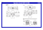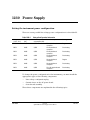
1
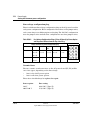
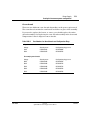
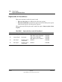
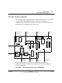
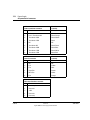
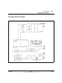
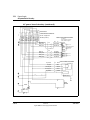
1230 Power Supply
Setting the instrument power configuration
There are seven possible line voltage power configurations for the 6890 GC.
Table 1230-1
Voltage Configuration Information
Voltage
(–10%, +5%)
Frequency
(Hz)
Maximum power
consumption (VA)
Power line requirement
Oven type
120 V
48-66
2,250
20-amp dedicated
receptacle
Regular
200 V
48-66
2,950
15-amp dedicated
receptacle
Fast-heating
208 V
48-66
2,950
15-amp dedicated
receptacle
Fast-heating
220 V
48-66
2,950
15-amp dedicated
receptacle
Fast-heating
230 V
48-66
2,250
10-amp dedicated
receptacle
Regular
230 V
48-66
2,950
16-amp dedicated
receptacle
Fast-heating
240 V
48-66
2,950
13- or 16-amp dedicated
receptacle
Fast-heating
To change the power configuration for the instrument, you must install the
appropriate types of the following components:
•
•
•
Line voltage configuration plug
Ceramic fuses on the AC power board
Oven shroud assembly
These three components are explained in the following topics.
Jun 2001
Electrical
Agilent 6890 Gas Chromatograph Service Manual
1 of 10
1230
Power Supply
Setting the instrument power configuration
Line voltage configuration plug
There is a different line voltage configuration plug on the AC power board for
each power configuration. Each configuration uses three or five jumper wires,
each connecting to two different pins on the plug. The 120 VAC configuration
uses five jumper wires and all other configurations use three jumper wires.
Table 1230-2
Line Voltage Configuration Plugs (P8 on AC board) by Power Option
and Diagram of Pinouts from the Top of the Plug
Jumper locations for power configuration plug
Transformer
120 VAC
200 VAC
208/220
VAC
230 VAC
240 VAC
3 ↔ 13
2 ↔ 13
3 ↔ 13
5 ↔ 13
3 ↔ 13
6 ↔ 15
6 ↔ 12
6 ↔ 12
6↔9
6↔9
9 ↔ 14
Oven fan
1 ↔ 10
1↔4
1↔4
1↔4
1↔4
3
2
1
6
5
4
9
8
7
12
11
10
15
14
13
4↔8
Ceramic fuses
The two ceramic oven heater fuses on the AC power board (F1, F2) will be
one of two types, depending on the line voltage:
•
•
One for the 120 V power option
One for all other power options.
These fuses should always be replaced as a pair.
2 of 10
Power option
Fuse rating
120 V
200 V-240 V
20A/250 V (Type F)
15A/250 V (Type F)
Electrical
Agilent 6890 Gas Chromatograph Service Manual
Jun 2001
Power Supply
Setting the instrument power configuration
1230
Oven shroud
There are two different oven shrouds depending on the power option used.
The oven shroud contains the oven heater and sensor as part of the assembly.
If you need to replace the heater or sensor, you should replace the entire
shroud assembly. See Replacing the oven shroud assembly in the Oven and
Temperature Control chapter for more details.
Table 1230-3
Part Numbers for Oven Shrouds and Configuration Plugs
Regular oven shrouds
Voltage
Shroud part no.
Configuration plug part no.
120 V
G1530-61610
G1530-60690
230 V
G1530-61670
G1530-60720
Fast ramping oven shrouds
Jun 2001
Voltage
Shroud part no.
Configuration plug part no.
200 V
G1530-61620
G1530-60700
208 V
G1530-61630
G1530-60710
220 V
G1530-61630
G1530-60710
230 V
G1530-61650
G1530-60720
240 V
G1530-61640
G1530-60730
Electrical
Agilent 6890 Gas Chromatograph Service Manual
3 of 10
1230
Power Supply
Replaceable AC board fuses
Replaceable AC board fuses
There are four fuses on the AC power board.
•
•
The two glass fuses are identical for all power options.
The two ceramic fuses come in two types: one for the 120 V power option
and another type for all other power options.
When replacing both the glass and ceramic fuse types, always replace them
in pairs.
Table 1230-4
Replaceable Fuses on the AC Power Board
I.D.
Description
System
Power rating
Part no.
F1
Ceramic/Type F
Oven heater
120 V systems: 20A/250 V
200 V–240 V systems: 15A/250 V
2110-0098
2110-0054
F2
Ceramic/Type F
Oven heater
120 V systems: 20A/250 V
200 V–240V systems: 15A/250 V
2110-0098
2110-0054
F3
Glass/Type F
All other systems
except heater
8A/250 V
2110-0036
F4
Glass/Type F
All other systems
except heater
8A/250 V
2110-0036
4 of 10
Electrical
Agilent 6890 Gas Chromatograph Service Manual
Jun 2001
Power Supply
AC power board connectors
1230
AC power board connectors
The following tables are the pinouts for the internal connectors on the main
circuit boards in the instrument. These connectors are used for
communications within the instrument. All connector pinout drawings are
viewed from the component side of the board.
Main board interface
connector
P9
Oven triac
connectors*
Oven fuses
Main power
fuses
T1
C2
K1
P4
P3
Oven heater
connectors
F3
F4
S1
P10
P6
F2
P8
F1
P5
P2
J1
P7
P1
Transformer
connector
C1
Configuration
jumper plug
Oven fan
connector
Line1
(Black, Brown)
Line 2, Neutral
(White, Blue)
*On some AC power boards, the oven triac is mounted directly onto the AC board
while on others it mounts on the GC through a cutout in the AC board. Both configurations
are the same electrically.
Figure 1230-1
Jun 2001
AC power board overlay (part no. G1530-60050)
Electrical
Agilent 6890 Gas Chromatograph Service Manual
5 of 10
1230
Power Supply
AC power board connectors
J1
Power transformer connector
Transformer
assembly
Pin
Function
Wire color
1
NC
NC
2
Line 1/Transformer 0A
Black/Orange
3
Transformer 100A
Black/Yellow
4
Transformer 120A
Black
5
NC
NC
6
Transformer 0B
Black/Green
7
Transformer 100B
Black/Blue
8
Transformer 110B
Black/White
9
Transformer 120B
Black/Red
P7
Oven fan connector
Motor
assembly
Pin
Function
Wire color
1
NC
NC
2
Fan
Yellow
3
Fan
Blue
4
Oven/Fan
Brown
5
MT1/Fan
White
6
Fan
Orange
P9
Main board interface connector
6 of 10
Pin
Function
1
Oven relay
2
Oven triac
3
+24V
4
Oven triac
5
Oven relay
Electrical
Agilent 6890 Gas Chromatograph Service Manual
Jun 2001
Power Supply
AC power board circuitry
1230
AC power board circuitry
1
LM1/XFRMR OA
Main power switch
2
BA, 250 VAC
Fast-acting, 3AG
p/n 2110-0036
Glass body
(Actuated by
push-rod from
LN2/Neutral
front of unit)
Line 1
(Black, Brown)
Line
voltage
120 V:
AC LINE INPUT
Oven circuit
Fuse rating
20A, 250 VAC
200-240V:
p/n
2110-0098
2110-0054
15A, 250 VAC
All fuses: 3AB, IEC 127 TYPE F,
(fast-acting), Ceramic Body
Line 2
Neutral
(White, Blue)
3
4
Primary circuits
Secondary circuits
Main board interface
PS
5
Oven fly
Oven triac
+24V
6
Oven triac
Oven fly
Secondary circuits Primary circuits
Jun 2001
Electrical
Agilent 6890 Gas Chromatograph Service Manual
7 of 10
1230
Power Supply
AC power board circuitry
1
2
LN2/Neutral 13
LN2/Neutral 14
LN!/XFRMR_OA15
XFRMR_120A 9
OVN/FAN_BRN10
MT1/FAN WHT 11
XFRMR_100A 12
XFRMR_120B 3
FAN_ORANGE 4
XFRMR_110B 5
XFRMR_OB
6
7
TRIAC_MT2
FAN_YELLOW 8
Fan_Blue
P8
XFRMR_100B 2
P8
1
AC power board circuitry (continued)
LINE VOLTAGE
CONFIGURATION CONNECTOR
(shown configured for
120 VAC operation)
POWER TRANSFORMER ASSEMBLY
Secondaries
Violet- Orange: Heater Power
Yellow- Yellow: dc Supplies
LN!/XFRMR_OA
BLK
XFRMR_100A
BLK/ORN100V
OV
XFRMR_120A
BLK/YEL 120V
VIOLET
42 V(rms) - nos.
GRAY
WHITE
Commonly-grounded
on Main Board
42 V(rms) - nos.
ORANGE
XFRMR_08
BLK/GRNOV
XFRMR_100B
BLK/BLU100V
XFRMR_110B
BLK/WHT110V
XFRMR_120B
BLK/RED120V
YELLOW
BLUE 24 V(rms) - nos.
YELLOW 24 V(rms) - nos.
OVEN FAN MOTOR ASSEMBLY
FAN_YELLOW
FAN_BLUE
YELLOW
BLUE
OVN/FAN_BRN
BROWN
MT1/FAN_WHT
WHITE
FAN_ORANGE
ORANGE
3
GREEN/YELLOW
4
OVEN
HEATER
5
TRIAC
6
8 of 10
Electrical
Agilent 6890 Gas Chromatograph Service Manual
Jun 2001
Power Supply
Testing resistance of the heater coil
1230
Testing resistance of the heater coil
If you believe that your heater coil is cracked or otherwise damaged and has
caused an open circuit, you can check it by measuring its resistance.
To measure the resistance:
1.
Turn the instrument power off.
2.
Disconnect the oven heater leads (P3, P4) from the AC power board.
3.
Use an ohmmeter to measure resistance at the connectors.
Acceptable resistance ranges (in ohms) are given below. Acceptable
resistances range from the nominal value for a new, cold heater to +5% from
the nominal value.
Note
Resistance goes up approximately +3% after heating the coil.
Table 1230-5
Resistances of the Heater Coil
Nominal cold heater resistances
Standard oven
(1600 VA)
Fast-ramp oven
(2250 VA)
120 V
9.07 – 9.52 Ω
n/a
200 V
n/a
17.78 – 18.7 Ω
220 V
n/a
21.51 – 22.6 Ω
230 V
33.06 – 34.71 Ω
23.51 – 24.7 Ω
240 V
n/a
25.60 – 26.9 Ω
n/a = not available
Jun 2001
Electrical
Agilent 6890 Gas Chromatograph Service Manual
9 of 10
1230
10 of 10
Power Supply
Testing resistance of the heater coil
Electrical
Agilent 6890 Gas Chromatograph Service Manual
Jun 2001