1
CHAPTER 7
SUSPENSION
Rear Suspension Operation ............................ 7.1-7.2
Rear Suspension Tuning .............................. 7.3
Tunnel Mounting . . . . . . . . . . . . . . . . . . . . . . . . . . . . . . . . . . . . . 7.4
Hi-Fax Inspection/Replacement ........................ 7.5-7.6
Suspension Lubrication Points/Torque Specifications ...... 7.7
Wheel Kits ........................................... 7.8-7.10
Widetrak LX Rear Suspension Exploded View ............ 7.11
Rear Suspension Components Widetrak LX/Tran Sport . . . . 7.12
Tran Sport Rear Suspension Exploded View . . . . . . . . . . . . . 7.13
Rear Suspension Adjustment, Widetrak LX/Tran Sport . . . . 7.14
XTRA Lite Rear Suspension Exploded View .............. 7.15
Rear Suspension Components XTRA Lite . . . . . . . . . . . . . . . 7.16
Rear Suspension Adjustment, XTRA Lite ................ 7.17-7.18
XTRA 10 Rear Suspension Exploded View . . . . . . . . . . . . . . . 7.19
Rear Suspension Components XTRA 10 121" ............ 7.20-7.21
Rear Suspension Components XTRA 10 133.5, 136" ...... 7.22
Rear Suspension Adjustment, XTRA 10 . . . . . . . . . . . . . . . . . 7.23
Front Rear Scissor Stop (FRSS) XTRA-10 Style .......... 7.24
Rear Rear Scissor Stop (RRSS) XTRA-10 Style .......... 7.25
Rear Suspension Exploded View - XTRA 12 121" . . . . . . . . . 7.26
Rear Suspension Exploded View - XTRA 12 133.5" . . . . . . . 7.27
Rear Suspension Components XTRA 12 ................ 7.28-7.29
IFS Front Torque Arm Limiter Strap Adjustment, X-12 ..... 7.30
Rear Suspension Adjustments, XTRA 12 ................ 7.31-7.32
IFS Adjustments, XTRA 10 and 12 ...................... 7.33-7.34
Compression Adjustable Shocks ........................ 7.35-7.36
Suspension Springs and Rails .......................... 7.37
Optional Springs - 1999 XTRA Lite/Tran Sport!Widetrak LX
7.38
Optional Springs - 1999 XTRA-1 0 Style . . . . . . . . . . . . . . . . . . 7.39
Optional Springs- 1999 XTRA-12 Style .................. 7.40
Front Track Springs . . . . . . . . . . . . . . . . . . . . . . . . . . . . . . . . . . . 7.41
XTRA-12 Suspension- Shock Removal ................. 7.42
IFS Fox"' Shock Specifications ......................... 7.43
Rear Suspension Fox"' Shock Specifications ............ 7.44
Typical Shock Valving Arrangement . . . . . . . . . . . . . . . . . . . . . 7.45
1997-1999 Production Valving Chart . . . . . . . . . . . . . . . . . . . . 7.46
1999 Optional Valving by Shock Part Number ............ 7.47-7.48
Valve Washer Part Numbers ........................... 7.49
Fox"' Shock Maintenance ............................. 7.50-7.58
Polaris Position Sensitive Shock (PSS) .................. 7.59-7.68
Suspension Troubleshooting ........................... 7.69-7.72
SUSPENSION
Rear Suspension Operation
Refer to Specifications Section in Chapter 1 for Suspension Type I Model Application
Rear Suspension Operation
The primary function of the rear suspension is to provide a comfortable ride in all types of riding conditions. It
separates the rider from the ground, while allowing for complete vehicle control. The rear suspension also must
provide weight transfer and maintain track tension.
The rear suspension has many adjustable features for fine tuning to achieve optimum comfort. The suspension
can be adjusted to suit rider preference and deliver excellent performance for a given set of conditions. It should
be noted, however, that suspension adjustments involve a compromise or trade off. A machine set up to perform
well in the moguls would not suit the preference of a groomed trail rider.
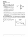
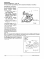
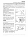
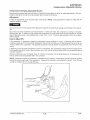
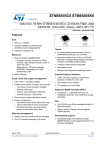
Weight Transfer
The shifting of weight from the
skis to the track is called weight
transfer. As engine torque is applied to the drive axle the torque
is transferred to the track, pulling
it forward. This energy also tries
to pull the suspension forward.
The front torque arm reacts to
this force by pushing down on
the front of the track, in effect applying more weight to the front of
the track and reducing the
weight on the skis. It is important
to note that energy used to lift
the front of the machine is not
available to push the vehicle forward.
Changing the angle of the front torque arm changes the suspension's reaction to the force. Adjusting the length
of the limiter strap will change the front torque arm angle. Shortening the strap limits the extension of the front
of the suspension; reducing the angle of the torque arm and increasing ski pressure during acceleration. Lengthening the strap allows the front of the suspension to extend further; increasing the angle of the torque arm and
decreasing ski pressure during acceleration. Limiter strap adjustment has a great affect on weight transfer. Limiter straps only affect acceleration. It is important to check track tension whenever limiter strap length is changed.
Front track shock spring preload also affects weight transfer. A stiffer spring and/or more preload on the spring
transfers more weight to the track. A softer spring and/or less preload keeps more weight on the skis. Keep your
riding application in mind when choosing springs and setting spring preload. Soft springs/preload will increase
ski pressure, but may bottom out. Stiff springs/preload will provide more track pressure (reduced ski pressure),
but may result in a less comfortable ride.
During acceleration, the rear of the suspension will compress and the IFS will extend, pivoting the machine about
the front torque arm. Because of this pivoting effect, rear spring and spring preload also have some effect on
weight transfer. Softer rear springs, or less preload, allow more weight transfer to the track and reduce ski pressure. Stiffer rear springs, or increased preload, allow less weight transfer to the track and increase ski pressure.
The main function of the rear torque arm is to support the weight of the vehicle and rider, as well as to provide
enough travel to absorb bumps and jumps.
Shock valving also has an effect on weight transfer. Refer to shock tuning information in this chapter.
Scissor stops also affect weight transfer. See scissor stop information in this chapter.
Polaris Industries Inc.
7.1
8/98
SUSPENSION
Rear Suspension Operation
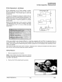
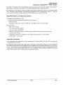
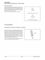
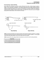
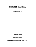
Springs
Two types of springs are employed in Polaris suspensions, coil springs and torsion springs. Following is some
of the terminology used when referring to coil springs.
Coil Spring
Length
•
Free length - the length of a coil spring with no load applied to the spring
•
Installed length - the length of the shock absorber between the spring retainers. If the installed length of the
spring is less than the free length, it will be pre-loaded.
•
Spring rate- the amount of force required to compress
a coil spring one inch. For example, if 150 pounds of
force are required to compress a spring 1 inch, the
spring rate would be 150 #/in.
•
Straight rate spring- the spring requires the same amount of force to compress the last one inch of travel as
the first one inch of travel. For example, if a 150 #/in. spring requires 150 pounds of force to compress it one
inch, 300 pounds of force would compress it two inches, 450 pounds of force would compress it three inches,
etc.
•
Progressively wound spring- the rate of the spring increases as it is compressed. For example, a 100/200
#/in. rate spring requires 100 pounds of force to compress the first one inch, but requires 200 additional
pounds to compress the last one inch.
Installed
Length
When a bump is encountered by the suspension, the force of the bump compresses the spring. If the force were
450 pounds, a 100 #/in. spring would compress 4.5 inches. A 150 #/in. spring would only compress 3 inches.
If the suspension had 4 inches of spring travel the 100 #/in. spring would bottom out, while the 150 #/in. spring
would have one inch of travel remaining.
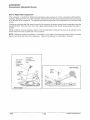
Torsion springs are much like coil springs, although
shaped differently. The rate of the torsion spring is controlled by the free opening angle, the installed opening
angle, the wire diameter of the spring, and the number of
coils.
Torsion Spring
Load reduces
opening angle
r:o~~ ~ ~ ~ ~
8/98
7.2
Polaris Industries Inc.
SUSPENSION
Rear Suspension Tuning
Many factors influence the overall handling characteristics of snowmobile suspensions. Rider weight, riding style,
course conditions, and the condition of suspension components are some of the things that you have to consider
when tuning a suspension.
On new machines, or whenever new suspension parts are installed, the sled should be ridden for at least one
tank of fuel to allow moving parts in the shocks and suspension to wear in. The shock springs will also take their
initial set and the setup will be more accurate.
•
Front Suspension: The front suspension should sag (unloaded) about 1" (measured at the front bumper)
with the weight of the sled. Use stiffer or softer springs as needed to keep from bottoming too hard, and to ensure
the entire range of travel is used.
Rear Suspension Tuning
To begin suspension tuning, check the condition of shocks and other suspension parts.
•
Inspect and grease all suspension parts, making sure they pivot freely. All suspension components should
be greased when disassembled. Regular maintenance greasing should be done with no weight on the component
to allow grease to reach important contact areas.
•
Loaded Sag: Set the preload on the rear springs for the correct sag. There should be 1 1/2" of sag on the
rear suspension when the rider on the snowmobile, measured at the rear bumper. Bounce on the suspension
a couple of times to overcome any "stiction" and settle the sled to an accurate reference point. The rider should
have their weight placed correctly on the machine. Adjust spring preload to achieve the 1 1/2" sag dimension.
•
Unloaded (Free) Sag: When the rider gets off the machine, the suspension should return to 1/2" of sag.
If the sag is less than 1/2" stiffer springs may be needed. If it is greater than 1/2" softer springs may be needed.
This may seem backwards at first, but if the spring is too soft, the preload must be greatly increased to prevent
excess loaded sag. This shows up in the form of less unloaded sag. Therefore, a stiffer spring is required. If
the spring is too stiff, the preload will have to be backed off, and unloaded sag will be excessive. This is a very
important step because the proper spring will also help ensure correct weight transfer.
Shock Tuning
The shocks work in two directions. Compression damping prevents the shock from bottoming hard while rebound
damping keeps the shock from springing back too fast. Both compression and rebound damping can be adjusted
for high and low speed damping characteristics. On Indy Select shocks, the compression damping can be
changed by turning the adjuster screw. Refer to shock section in this chapter for adjustment. NOTE: When we
refer to high and low speed, we are referring to the speed of the shock shaft or valve, not vehicle speed.
Rebuildable Shocks
Begin by taking the shocks apart, inspecting all parts for damage, and changing the oil. Even new shocks should
get an oil change after break in to clean break-in material from the shocks and valve body.
If oil is low, inspect seal cap 0-Ring and seals for damage. If air or foam is evident in the oil, the 0-Ring in the
floating piston must be replaced. After changing the oil reassemble shocks, making sure oil level, floating piston
depth (IFP), and nitrogen pressure are correct.
The use of nitrogen in Fox™ shocks provides consistent damping at extreme temperatures. Don't overcharge
the shocks. Excess nitrogen pressure may cause seal "stiction" and prevent proper shock action. If too much
oil is added, or if the IFP depth is set incorrectly (too low) shock travel will be limited.
Polaris Industries Inc.
7.3
8/98
SUSPENSION
Tunnel Mounting
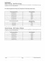
1999 Rear Suspension Set Up I Tunnel Mounting Positions
Model
340/340 Deluxe
Front Limiter
Strap
Rear Limiter
Strap
Rear Torque
Arm Tunnel
Mount
Front Track
Shock Mount
Std
NIA
No Options
N/A
340 Touring
Std
N/A
No Options
N/A
Sport
Std
NIA
No Options
N/A
Sport Touring
Std
N/A
No Options
N/A
TranSport
Std
N/A
No Options
N/A
Quick Adjust
Quick Adjust
No Options
Lower
XCF
Front Torque
Arm Tunnel
Mount
440 XCR
Quick Adjust
Quick Adjust
No Options
Lower
Trail
Quick Adjust
Quick Adjust
No Options
Lower
Trail Touring
Std
Std
No Options
Lower
Trail RMK
Std
N/A
No Options
Upper
Super Sport
Quick Adjust
Quick Adjust
No Options
Lower
WideTrak LX
Std
N/A
No Options
N/A
500
Quick Adjust
Quick Adjust
No Options
Lower
500 RMK
Quick Adjust
Quick Adjust
No Options
Upper
500 XC/SP
Quick Adjust
Quick Adjust
No Options
Lower
Classic
Std
N/A
No Options
N/A
Classic Touring
Std
N/A
No Options
N/A
c.c
XLT Special
Quick Adjust
Quick Adjust
No Options
Lower
""C
0
XLT Touring
Std
N/A
No Options
N/A
XLT Classic
Std
N/A
No Options
N/A
a:
0
600 XC/SP
Quick Adjust
Quick Adjust
No Options
Lower
600 RMK
Quick Adjust
Quick Adjust
No Options
Upper
700 XC/SP
Quick Adjust
Quick Adjust
No Options
Lower
700 XCR
Quick Adjust
Quick Adjust
No Options
Lower
700 RMK
Quick Adjust
Quick Adjust
No Options
Upper
700 SKS
Quick Adjust
Quick Adjust
Below(See Ill.)
Lower
800 XCR
Quick Adjust
Quick Adjust
No Options
Lower
z
0
0
"0
:!'.
0
:l
!l)
:s::
0
t:
:l
::!:
:l
en
:l
en
NOTE: There are no optional front torque arm mounting positions. Do not re-locate the front torque arm.
700 SKS stock mounting position.
Optional position - lower hole.
Rear
Optional mounting hole for deep snow.
*If mounting here place dummy bolt (PN
7517388) in upper hole to secure rear suspension mounting pad.
8/98
7.4
Front torque arm
stock mounting position.
No optional positions.
Polaris Industries Inc.
SUSPENSION
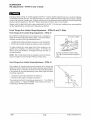
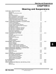
Hi-Fax Inspection I Replacement
Hi-Fax Replacement - All Models
Hi-Fax replacement on all Polaris models is similar.
When any area of the Hi-Fax is worn to 1/8" (.3 em), it
should be replaced. This will save wear on other vital
components.
Hi Fax Wear Limit
The slide rail is designed to operate in conditions with adequate snow cover to provide sufficient lubrication. Excessive wear may be due to improper alignment, improper track adjustment or machine operation on surfaces
without snow.
Replace Hi-Fax when worn to 5/16" (.79 em) on XTRA
12 suspensions; 3/8" (.95 em) on XTRA 10 and Sport
style suspensions; 7/16" (1.1 em) on XTRA Lite style
suspensions.
1~!i~~\d~~f~\f~r,~:~~·
',)(J;RA12- 5/16"(.79 em) ,. ,,
:;q*··i~\~:)::¥,;:-l~··· fi~:// ~:0tk .~:~:. .·' .:· '.::
q
, XTRA"J ~ 3/8~i~(~95 em) .,
)
...
~'.
·····
.
Hi-Fax wear patterns are somewhat different on machines equipped with the XTRA 12 suspension than on
conventional models. The rear of the rail will wear rapidly at first. After this initial break in period, the rapid wear will
cease. This area should be checked frequently, however, replacement is not necessary until a thickness of 5/16"
(.79 em) is reached.
New Hi-Fax are best used in deep snow conditions. Marginal snow or hard-pack conditions are better suited to
worn Hi-Fax, or Hi-Fax which have been cured or broken in.
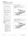
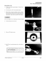
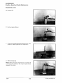
Hi-Fax Removal
1.
Remove suspension from machine.
NOTE: Some models may allow Hi Fax to be removed
by sliding it through track windows with the suspension
mounted in the machine.
2.
Remove front Hi-Fax retaining bolt as shown.
Polaris Industries Inc.
7.5
8/98
SUSPENSION
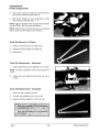
Hi-Fax Replacement
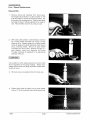
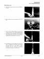
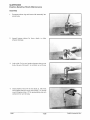
3.
Use a block of wood or a drift punch and hammer to
drive Hi-Fax rearward off the slide rail.
4.
With Hi-Fax material at room temperature, install
new Hi-Fax by reversing steps 1 - 3.
NOTE: Lightly coat Hi-Fax track clip area with a lubricant
such as LPS2 or WD-40 to ease installation.
NOTE: Wide Hi-Fax should be narrowed on the leading
sides to allow it to fit through narrow windows.
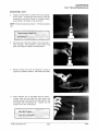
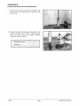
Track Clip Removal - All Types
1.
Position removal tool jaws on edge of clip.
2.
Squeeze handles together to spread clip.
3.
Remove clip.
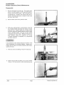
Track Clip Replacement - Yokohama
1.
Install replacement clip and clipping tool as shown.
NOTE: For ease of operation, the tool may be placed in
a vise.
2.
Tighten drive bolt against forming die until clip is
formed.
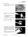
Track Clip Replacement - Camoplast
1.
Place new clip in position on track.
2.
Connect clip installation tool on top of clip.
3.
Squeeze handles together to crimp new clip.
>r+'·~~v\,\~" .,/'
).:..
,,·'i;,,ttr. ·,<Bf*'. :\{;-;, .. ,,<r. iit;~~l'~'<···.· .~k~~· .
, .Tra~kwP!!P lns~f!!l~t.i,c)ll :rqo!~(Cam9plast)i
1
' ·.
·~;N ~87~b4t4~~F:t<J~t ,%;:, .,
"''w~Jxf>.'~j
0
Tra6k Clip
lnst~·nationT~ol {Yokohama)··
l~\,,P~~,~~~~~~O
8/98
•.•~~;?:.r•:;:~·
. .· ,.
.· ., ;
7.6
Polaris Industries Inc.
SUSPENSION
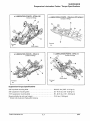
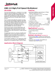
Suspension Lubrication Points I Torque Specifications
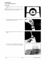
* LUBRICATION POINTS- XTRA LITE
* LUBRICATION POINTS- Widetrak LX/TranSport
Grease at fittings
Grease at fittings
*
*
--
Forward
--
Forward
*
(Both sides)
* LUBRICATION POINTS- XTRA-1 0
*
*LUBRICATION POINTS- XTRA-12
Grease at fittings
Grease at fittings
*
*
(Both sides)
--
Forward
--
Forward
*
*
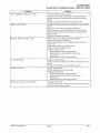
Suspension Torque Specifications
3/8" top shock mounting bolts .................................. 28-30 ft. lbs. (3.85 - 4.14 kg-m)
3/8" suspension mounting bolts ................................ 35- 40ft. lbs. (4.8- 5.52 kg-m)
7/16" suspension mounting bolts ............................... 55-60ft. lbs. (7.61 -8.30 kg-m)
Shock rod bolts (do not over torque) ............................ 12ft. lbs. (1.66 kg-m)
* Shock rods must pivot freely after torquing
Polaris Industries Inc.
7.7
8/98
SUSPENSION
Wheel Kits
Wheel Kit Mounting Recommendations
The following illustrations indicate proper installation of optional wheel kits.
XTRA Lite
NOTE: If installing optional rear
wheel kit, rear scissor must be
mounted in rear hole.
XTRA 10 121"
Inside Kit PN 2870602
8/98
7.8
OutsideKit PN 2871582
Polaris Industries Inc.
SUSPENSION
Wheel Kits
Wheel Kit Mountin g Recommendat·1ons
XTRA 10 133.5"
OuterKit PN 2870602
InnerKit PN 2871582
Outer_
Kit PN 2871582
XTRA 10 136"
InnerKit PN 2871582
OuterKit PN 2871582
OuterKit PN 2870602
Polaris Industries Inc.
7.9
8/98
SUSPENSION
Wheel Kits
Wheel Kit Mounting Re commendations
XTRA 12 121"
OuterKit PN 2870602
OuterKit PN 2871582
XTRA 12 133.5"
No Wheel Kits re:commended
for this suspension
8/98
7.10
Polans
. Industries Inc.
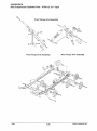
SUSPENSION
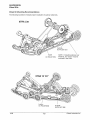
WideTrak LX Style - Exploded View
'
Front Torque Arm
Polaris Industries Inc.
Rear Torque Arm
7.11
'
8/98
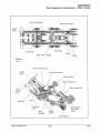
SUSPENSION
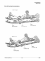
Rear Suspension Components WideTrak LX I TranSport
Rear Torque Arm
Rear Shock
Adjuster
Eye bolt
Carrier Wheel
Rail Tip
Rear Pivot Arm
Front Track Shock
Front Track Spring
-
Forward
Hi-fax
Bogie Wheel
Slide Rail
Rail Bumper
Idler Wheel
8/98
7.12
Polaris Industries Inc.
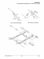
SUSPENSION
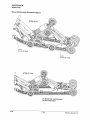
TranSport Style - Exploded View
Rear Torque Arm
Front Torque Arm
\
Polaris Industries Inc.
7.13
8/98
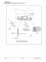
SUSPENSION
Suspension Adjustment - WideTrak LX I TranSport
The Polaris WideTrak LX and TranSport suspension has been designed and set up to deliver a soft ride under
average riding conditions. Rider weight, riding styles, trail conditions, and vehicle speed each affect suspension
action.
The suspension can be adjusted to suit rider preference and deliver excellent performance for a given set of conditions. It should be noted, however, that suspension adjustments involve a compromise or trade off. A machine
set up to perform well in the moguls would not suit the preference of a groomed trail rider.
Adjustable Features and Adjustment Options
• IFS compression spring preload
• Rear torsion spring preload
• Rear shock compression (if equipped with Indy Select shock)
• Optional coil springs for front track shock
Adjustment Procedures
It is a good idea to have customers break the suspension in for approximately 150 miles (240 km) before fine
tuning adjustments are made.
All settings will vary from rider to rider, depending on rider weight, vehicle speed, riding style, and trail conditions.
We recommend starting with factory settings and then customizing each adjustment individually to suit rider preference. The machine should be methodically tested under the same conditions after each adjustment (trail and
snow conditions, vehicle speed,riding position, etc.) until a satisfactory ride is achieved. Adjustments should be
made to one area at a time, in order to properly evaluate the change.
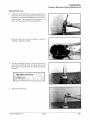
The purpose of the front track shock coil spring is to control ride height. If you find that in order to obtain the desired
ride effect the spring preload is at its maximum, consider removing the existing spring and installing the next highest rate spring.
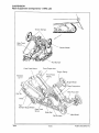
Rear Suspension Adjustments - WideTrak LX
The primary adjustment for riding comfort is rear torsion spring preload adjustment. To check for the recommended settings:
1.
Lift the rear of the machine to relieve the rear springs.
2.
Slowly lower the machine and measure the distance between the ground and the running board at the rear of
the tunnel.
3.
Without letting the suspension settle, the rider should carefully mount the snowmobile.
4.
Measure the distance between the ground and the same spot on the running board.
If the difference is greater than 1 1/2", the rear spring should be adjusted equally on both sides until the desired
1 1/2" drop is obtained.
Compensating adjustments for heavy or
light drivers or cargo loads can be made
by adjusting the rear torsion spring eye
bolt (A) length. Adjust spring tension so
there is equal tension on the long leg of
each spring.
Torsion Springs
NOTE: Rear torsion spring settings will
affect ski-to-ground pressure. It may be
desirable to tighten rear torsion springs
for an increase in ski-to-ground pressure. If ski pressure is too light, the machine will be hard to steer around curves
and will tend to push, or drive straight
through curves.
8/98
7.14
Polaris Industries Inc.
SUSPENSIC?N
Rear SuspensJ·on Explode d View- XTRA L1te
spring
Front trac k shockPN
preload washers
5210953.
~~,
I' ' \ '
Arm
Rear Torque
I'
Arm
1'
Fron t Torque
. Industries Inc.
Polans
7.15
8/98
SUSPENSION
Rear Suspension Components - XTRA-Lite
Rear Track
Shock
Rail Bumper
Front Track Shock
Front Torque Arm
-
Forward
Rail Tip
Rail
Bumper Bogie Wheel
·
Rear Track
Shock
Rail Bumper
8/98
7.16
Polaris Industries Inc.
SUSPENSION
Suspension Adjustment - XTRA Lite
Suspension Adjustment
The Polaris suspension has been designed and set up to deliver a soft ride under average riding conditions. Rider
weight, riding styles, trail conditions, and vehicle speed each affect suspension action.
The suspension can be adjusted to suit rider preference and deliver excellent performance for a given set of conditions. It should be noted, however, that suspension adjustments involve a compromise or trade off. A machine
set up to perform well in the moguls would not suit the preference of a groomed trail rider.
Adjustable Features and Adjustment Options
• Rear torsion spring preload
• Optional coil springs for front track shock and spring preload washers
• Optional torsion springs
• Front limiter strap
• Optional coil springs for IFS shocks
Adjustment Procedures
It is a good idea to break the suspension in for approximately 150 miles (240 km) and re-grease all suspension
parts before fine tuning adjustments are made.
All settings will vary from rider to rider, depending on rider weight, vehicle speed, riding style, and trail conditions.
We recommend starting with factory settings and then customizing each adjustment individually to suit rider preference. The machine should be methodically tested under the same conditions after each adjustment (trail and
snow conditions, vehicle speed,riding position, etc.) until a satisfactory ride is achieved. Adjustments should be
made to one area at a time, in order to properly evaluate the change.
The purpose of the front track shock coil spring is to control ride height and front IFS preload. If you find that in
order to obtain the desired ride effect the spring preload is over four additional washers (total of five), consider
removing the existing spring and installing the next highest rate spring.
Polaris Industries Inc.
7.17
8/98
SUSPENSION
Suspension Adjustment - XTRA Lite
For Recommended Optional Settings, Refer to Suspension Set Up Decal Under Hood
Rear Suspension Adjustments
The primary adjustment for riding comfort is rear torsion spring preload adjustment. To check for the recommended initial settings:
1.
Lift the rear of the machine to
relieve the rear springs.
2.
Slowly lower the machine and
measure the distance between the
ground and the running board at
the rear of the tunnel.
3.
Without letting the suspension
settle, the rider should carefully
mount the snowmobile.
4.
Measure the distance between the
ground and the same spot on the
running board.
Torsion Springs
Torsion Spring
Preload Adjuster
-
Forward
If the difference is greater than 1 1/2",
the rear spring should be adjusted
equally on both sides until the desired
1 1/2" drop is obtained. See adjustment information below.
Compensating adjustments for heavy
or light drivers or cargo loads can be
made by adjusting the preload adjuster. Remember, this is only the initial
settings. Final settings should be determined by riding the snowmobile and
readjusting.
NOTE: Rear torsion spring settings will affect ski-to-ground pressure. It may be desirable to tighten rear torsion
springs for an increase in ski-to-ground pressure. If ski pressure is too light, the machine will be hard to steer
around curves and will tend to push, or drive straight through curves.
The XTRA Lite suspension comes from the factory with
the rear suspension pivot mounted in the second hole
from the front of the rail. Do not move to the front
mounting hole.
These holes
used for
extra bogie
wheel
placement
only
#1 - stock position
-
Forward
8/98
7.18
#2 - use to stiffen
rear suspension
Polaris Industries Inc.
SUSPENSION
Rear Suspension
Exp Io ded View - XTRA 10 Style
.
Front Torque Arm
Polaris Industries Inc.
Rear Torque Arm
7.19
8/98
SUSPENSION
Rear Suspension Components - XTRA 10 Style
Rear Limiter Strap Adjuster
Compression Valve Adjustment Screw
(Ryde AFX /Indy Select Shocks}
~
Rear Scissor
Rear Torsion Spring
Adjuster Cam (low Position Setting Shown}
FRSS (Front Rear
Scissor Stop}
RRSS (Rear Rear
Scissor Stop}
Limiter Strap (Adjustable}
Front Limiter
The front limiter strap controls the amount of weight transfer, ski pressure, and to some degree the ride height.
The rear limiter controls ride height and increases preload on the rear springs when tightened, which also decreases transfer (i.e. the lighter the torsion spring preload, the more weight transfer).
Setting
Ski Pressure
Weight Transfer
Longer
Decreased
Increased
Shorter
Increased
Decreased
NOTE: RRSS has greatest affect on weight transfer on XTRA 10 suspensions. See pages 7.24-7.25.
8/98
7.20
Polaris Industries Inc.
SUSPENSION
Rear Suspension Components- XTRA 10 121" Style
Rear Limiter
Strap
Front Track Shock
Limiter
Strap
Front Torque
Arm Shaft
Pivot Arm
Shaft
Rear Torsion
Spring
Rear Torque
Arm
-
Forward
Carrier Wheel
Rear Torsion Spring
Limiter
Strap
I(J!I,I___
Bogie
Wheel
Slide Rail
Front Track Shock
Hi-fax
Polaris Industries Inc.
7.21
8/98
SUSPENSION
Rear Suspension Components - XTRA 10 133.5" /136" Style
Rear Limiter
Strap
Front Track Shock
Rear Track Shock
Limiter
Strap
Pivot Arm
Shaft
-
Rear Torsion Spring
Pivot Arm
Shaft
Forward
Carrier Wheel
Rear Track Shock
Rear Torsion Spring
Front
Torque
Arm
Limiter
Strap
Idler Wheel
Rail
Bumper
Slide Rail
Front Track Shock
Hi-fax
8/98
7.22
Polaris Industries Inc.
SUSPENSION
Suspension Adjustment- XTRA 10 Style
The XTRA™ 10 suspension has been designed and set up to deliver a soft ride under average riding conditions.
Rider weight, riding styles, trail conditions, and vehicle speed each affect suspension action.
The suspension can be adjusted to suit rider preference and deliver excellent performance for a given set of conditions. It should be noted, however, that suspension adjustments involve a compromise or trade off. A machine
set up to perform well in the moguls would not suit the preference of a groomed trail rider.
Adjustable Features and Adjustment Options
Independent Front Suspension (IFS)
• Front shock spring preload (some models require washers)
• Optional springs
• Adjustable compression valving via Ryde AFX I Indy Select shock (on some models)
Rear Suspension
• Rear torsion springs
• Front rear scissor stop (FRSS)
• Rear rear scissor stop (RRSS)
• Optional coil springs for front track shock and spring preload (some models require washers)
• Optional torsion springs
• Adjustable compression via Ryde AFX I Indy Select rear track shock (on some models)
• Limiter straps - front and rear
Adjustment Procedures
It is a good idea to have customers break the suspension in for approximately 150 miles (240 km) before fine
tuning adjustments are made.
All settings will vary from rider to rider, depending on rider weight, vehicle speed, riding style, and trail conditions.
We recommend starting with factory settings and then customizing each adjustment individually to suit rider preference. The machine should be methodically tested under the same conditions after each adjustment (trail and
snow conditions, vehicle speed,riding position, etc.) until a satisfactory ride is achieved. Adjustments should be
made to one area at a time, in order to properly evaluate the change.
Polaris Industries Inc.
7.23
8198
SUSPENSION
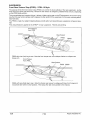
Front Rear Scissor Stop (FRSS) - XTRA 10 Style
The purpose of the front rear scissor stop (FRSS) is to control the bump attitude of the rear suspension. As the
front torque arm (FTA) hits the bump, it forces the rear scissor to collapse a predetermined amount, depending
on the FRSS block position.
This accomplishes two important things, it allows a lighter spring rate on the FTA because it can borrow spring
rate from the rear torsion springs; and it prepares the rear portion of the suspension for the bump, reducing secondary kick back.
The FRSS is made of a resilient material allowing smooth action and preventing any suspension component damage.
This unique feature is applied to the XTRA™ 10 rear suspension. Patents are pending.
Front Torque
Arm (FTA)
Rear Scissor
FRSS with short (low) leg to rear. Note the front torque arm must collapse further to collapse rear
torque arm.
Front Torque
Arm (FTA)
FRSS with long (high) leg to rear. Note this forces rear scissor to collapse with less front torque arm
movement than when in short position. This keeps the rails more parallel to the chassis.
8/98
7.24
Polaris Industries Inc.
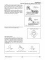
SUSPENSION
Rear Rear Scissor Stop (RRSS)- XTRA 10 Style
The RRSS controls weight transfer from the rear suspension to the skis. It also influences the stiffness of the
ride by controlling the amount of coupling action between the front and rear torque arms. To increase the
stiffness of the suspension, the RRSS should be set in
the high position.
RRSS -low
position shown
NOTE: On XTRA-1 0 models only, the RRSS can be totally removed for maximum weight transfer. However,
unless the torsion springs and rear shock valving are
changed, the ride will be compromised.
Always
maintain equal adjustment on both sides.
FRSS - low position shown
FRSS- medium position shown
Be sure rear scissor stop face is square with the face of
the scissor arm to ensure complete contact.
Scissor Stop Block Position
Medium
Low
Rear Spring Tension
High
Rear spring tension adjustments are made by rotating
the eccentric spring block (A) as shown with the engine
spark plug tool. The block provides three spring tension
positions. This adjustment is easier if the long spring leg
is lifted over the roller and replaced after the block is
properly positioned. Always maintain equal adjustment
on both sides.
A
Soft Tension Long End to Front
Polaris Industries Inc.
0
Low
0 "
Medium Tension (Short End Up)
7.25
Firm Tension (Long End Up)
8/98
SUSPENSION
Rear Suspension Exploded View- XTRA 12 121" Style
Front Torque Arm Assembly
@
Front Torque Arm Assembly
8/98
7.26
Rear Torque Arm Assembly
Polaris Industries Inc.
SUSPENSION
Rear Suspension Exploded View - XTRA 12 133.5" Style
Front Torque Arm Assembly
Polaris Industries Inc.
7.27
Rear Torque Arm Assembly
8/98
SUSPENSION
Rear Suspension Components - XTRA 12 Style
Limiter
Strap
Rear Torsion
Spring Adjuster Cam low position shown
Front Track
Shock
Preload Adjuster
FRSS
Front Track Spring
FRSS -"Front Rear Scissor Stop"
RRSS -"Rear Rear Scissor Stop"
8/98
7.28
Polaris Industries Inc.
SUSPENSION
Rear Suspension Components - XTRA 12 Style
Front Track Shock
Rear Track Shock
Limiter
Strap
Coil Spring
FRSS
Rear Torsion Spring
RRSS
-
Forward
Rear Torsion Spring
Limiter
Strap
Front Track Shock
Carrier Wheel
Rear Torque Arm
Front
Torque
Arm
Slide Rail
Pivot Arm
Shaft
Rear Scissor
Pivot Arm
Shaft
Rail
Bumper
Idler Wheel
Polaris Industries Inc.
7.29
8/98
SUSPENSION
Suspension Adjutment- XTRA-12 Style
The XTRA™ 12 suspension has been designed and set up to deliver a soft ride under average riding conditions.
Rider weight, riding styles, trail conditions, and vehicle speed each affect suspension action.
The suspension can be adjusted to suit rider preference and deliver excellent performance for a given set of conditions. It should be noted, however, that suspension adjustments involve a compromise or trade off. A machine
set up to perform well in the moguls would not suit the preference of a groomed trail rider.
Adjustable Features and Adjustment Options
Independent Front Suspension (IFS)
• Front shock spring preload
• Optional springs
• Compression adjust Indy Select I Ryde AFX shock
Rear Suspension
• Spring preload - front track shock
• Spring preload - rear track shock (Requires addition of washers)
• Rear torsion spring pre-load
• Front rear scissor stop (FRSS)
• Optional coil springs
• Optional torsion springs
• Limiter strap - front
• Compression adjust Indy Select Ryde AFX shock
Adjustment Procedures
It is a good idea to have customers break the suspension in for approximately 150 miles (240 km) and grease
all suspension pivots before fine tuning adjustments are made. Use Polaris Premium All Season Grease.
All settings will vary from rider to rider, depending on rider weight, vehicle speed, riding style, and trail conditions.
We recommend starting with factory settings and then customizing each adjustment individually to suit rider preference. The machine should be methodically tested under the same conditions after each adjustment (trail and
snow conditions, vehicle speed, riding position, etc.) until a satisfactory ride is achieved. Adjustments should be
made to one area at a time, in order to properly evaluate the change.
8/98
7.30
Polaris Industries Inc.
SUSPENSION
Rear Suspension Adjustments - XTRA 12 Style
The primary rear suspension adjustments are the front track spring preload and the rear torsion spring preload.
It is important to note that adjusting the limiter strap does not change weight transfer from the rear suspension
to the skis as in a conventional suspension. Instead it will increase the entire rear suspension preload and decrease travel. To increase ski pressure the front rear scissor stop (FRSS) should be set to low. To decrease ski
pressure the FRSS should be set to high.
To properly adjust the rear suspension, start with the lightest preload setting that will prevent heavy bottoming.
Remember: adjustments should be made to one area at a time, in order to properly evaluate the change.
NOTE: Rear spring settings will affect ski-to-ground pressure. If ski pressure is too light it may be desirable to
tighten rear springs for an increase in ski-to-ground pressure. It is also possible to reposition the FRSS for increased ski pressure.
Front Track Shock Spring
Front track shock spring preload is adjusted by grasping
the spring and turning in a clockwise direction to increase the preload. Turn in a counterclockwise direction
to decrease preload.
Rear Track Shock Spring
The rear track shock coil spring does not have a
threaded adjuster. Washers can be added to increase
preload. One option to decrease preload for extremely
light non-aggressive riders is removal of the rear track
shock spring.
Forward
....----
Mount limiter strap
on front of bracket
as shown
@
Front Rear Scissor Stop (FRSS)
To adjust the FRSS compress the rear portion of rear
suspension until the rear scissor pivots away from the
FRSS (Support front of track on object). Turn adjuster
to desired position. The dot on the stop indicates the
high position. High position is with the dot located toward
the rear of the machine (See illustration). Medium position is with the dot toward the front of the machine.
FRSS shown in high position, as indicated by dot on Rear
stop
@low
~medium
Be sure both blocks are in the same position or suspension damage may occur.
~high
-
Forward
NOTE: It may be necessary to loosen the FRSS mounting bolts to adjust the position. Tighten after adjustment.
If the FRSS is in the low position but additional ski pressure is desired, move the FRSS to the optional front hole.
Remove the attaching bolts and relocate the FRSS
blocks in the forwardmost hole. Reinstall bolts and tighten.
RRSS
Relocate FRSS to
forwardmost hole in rail for
additional ski pressure
Rear Rear Scissor Stop (RRSS)
The RRSS is not adjustable but can be changed to provide more or less weight transfer. See chart below.
XTRA 12 RRSS Production Settings
-
Forward
Suspension
Length
Color
121"
Short
Black
5410937 -more transfer
133"
Long
Gray
5411 041-less transfer
Polaris Industries Inc.
Part Number
7.31
8/98
SUSPENSION
Rear Suspension Adjustments - XTRA 12 Style
Rear Torsion Spring
hear torsion spring preload is adjusted by turning the two
position cams (A) on the short leg of the spring as shown
with the engine spark plug tool. This adjustment is easier
if the long spring leg is lifted over the roller and replaced
after the cam is properly positioned.
Always maintain equal adjustment on both sides.
~
A
Soft Tension Long End to Front
~
A
Firm Tension (Long End Up)
IFS ADJUSTMENTS
IFS Adjustments - XTRA-Lite I Widetrak LX I TranSport
IFS spring preload is one of the adjustment options which
affects ride. Preload is the initial compression placed on
the spring. The longer the installed length of the spring,
the less the amount of preload; the shorter the installed
length of the spring, the more the amount of preload. Increasing preload on the IFS spring will result in more bite
on the skis, but will require more effort to turn. The IFS
compression spring preload can be increased by adding
shims (PN 521 0953) under the spring.
Shims
Always verify ski alignment before making adjustments
to the IFS. See Body and Steering section.
8/98
7.32
Polaris Industries Inc.
SUSPENSION
IFS Adjustments- XTRA 10 and 12 Style
Front Suspension Setup and Adjustments
Spring preload is one of the adjustment options which affects
ride. Preload is the amount of pressure at which the spring is
held. The longer the installed length of the spring, the less the
amount of pre-load; the shorter the installed length of the spring,
the more the amount of pre-load. An increase in IFS shock
spring pre-load will result in an increase in ski pressure.
Turning
clockwise
increases
preload
To adjust front spring preload on threaded adjust models, grasp
the spring and turn in a clockwise direction (as viewed from the
bottom of the shock) to increase the preload. Turn in a counterclockwise direction to decrease preload.
In the adjacent illustration, high preload and low preload positions are depicted.
When adjusting, be sure springs on both the left and right sides
of the machine are at the same adjustment.
For the best ride the spring preload should be as low as possible.
Set the preload to use the full travel of the ski shock with occasional light bottoming.
Low Preload
/
High Preload
~
If the plastic nut is unscrewed from the threaded body the nut
will break. Always leave one thread showing above the plastic
nut or the spring coils will stack, resulting in damage.
For the best ride the spring preload should be as low as possible. Set the preload to use the full travel of the ski shock with
occasional light bottoming. To determine if your machine is using full travel, push the shock jounce bumper down as far as it
will go on the shock rod and test ride the machine.
Always
leave at
least
one thread
showing
above nut
The bumper will move up on the rod in direct relation to the
amount of travel. For example, if the shock travel is full, the
bumper will be seated at the top of the shock.
• Remove the existing spring and install the next highest
rate spring, or
• Reduce the preload on the existing spring and change the
shock valving to obtain the desired effect. NOTE: Shock
valving can only be adjusted or changed on models
equipped with Ryde AFX, Indy Select or Fox™ shocks.
Polaris Industries Inc.
7.33
Push
jounce
bumper
down as
far as it will
go on
shock rod
8/98
SUSPENSION
IFS Adjustments- XTRA-10 and 12 Style
A
WARNING
Changing shock valving on models equipped with Fox"' shocks requires special tools and a sound knowledge
of mechanical theory, tool use, and shop procedures in order to perform the work safely and correctly. Shocks
contain high pressure nitrogen gas. Extreme caution should be observed when handling and working with high
pressure service equipment. See Fox™ Shock rebuilding information later in this chapter.
Always verify ski alignment before making adjustments to the IFS. If the skis are misaligned, we recommend the
camber adjustment be checked as this may also be affected.
Front Torque Arm Limiter Strap Adjustment- XTRA-10 and 12 Style
Front Torque Arm Limiter Strap Adjustment- XTRA-10
One method of changing ski-to-snow pressure is to change the
length of the front torque arm limiter straps. The limiter strap is
normally mounted in the fully extended position.
Turn nut to adjust
• Lengthening the straps decreases ski pressure under acceleration.
• Shortening the straps increases ski pressure under acceleration.
To adjust models with quick adjust front limiter straps,turn the
eyebolt nut to lengthen or shorten the straps. To shorten the
strap, turn the nut clockwise. To lengthen the strap, turn the nut
counterclockwise.
NOTE: Both limiter straps must be adjusted evenly and remain
equal in length to avoid improper Hi-Fax and track wear.
Turning clockwise shortens strap.
Turning counterclockwise lengthens
strap.
Front Torque Arm Limiter Strap Adjustment- XTRA-12
One method of changing ski-to-snow pressure is to change the
length of the front torque arm limiter straps using the holes provided.
The limiter strap is normally mounted in the fully extended position.
It is important to note that decreasing limiter strap length will stiffen
the whole suspension.
• Lengthening the straps decreases ski pressure.
• Shortening the straps increases ski pressure.
The preferred method for changing ski pressure is 1. Turn FRSS to
a lower position. 2. Move the FRSS to the forward most hole. 3.
Increasing or decreasing IFS preload.
8/98
7.34
Polaris Industries Inc.
SUSPENSION
Compression Adjustable Shocks
Compression Damping Adjustable Shocks
Snowmobiles equipped with the Indy Select or Ryde AFX shocks allow the driver to make adjustments to the compression valving by turning the screw located near the base of the shock.
Adjustment
Locate the adjustment screw near the base of the shock. NOTE: This adjustment is easiest to make with the
machine tipped on its side.
A
WARNING
Be sure to shut off the fuel supply before tipping the machine to prevent fuel spillage and flooding of the carburetors.
By turning the screw clockwise (a small screwdriver or dime work well), the compression valving is increased,
stiffening the ride. To soften the ride, reduce the compression by turning the screw counter-clockwise. A great
deal of ride performance is accomplished with a mere 1/2 to 1 turns. There are approximately 3 full turns of adjustment available.
How to Adjust IFS
If the suspension is "bottoming," tighten the compression screw clockwise in 1/2 turn increments until the bottoming stops. Backing off 1/4 turn counter-clockwise at this point should give you the best possible ride ensuring use
of the full travel of the suspension. The opposite procedure should be used if the suspension is too stiff upon initial
set-up.
If bottoming continues after the screw is turned in full clockwise, the compression spring should be adjusted with
the threaded adjustment collar. Back the screw out to the original starting position after the compression spring
has been adjusted.
Riding conditions are ever changing. Keep in mind the compression damping adjustable can be adjusted at any
time to achieve the best possible ride in any condition.
NOTE: Whenever shocks are replaced or reinstalled for any reason, the adjustment screw should be located
toward the forward right side of the suspension. Access to the adjuster is not possible if reversed. Fox™ Shocks
should be installed with the charge fitting up.
Polaris Industries Inc.
7.35
8/98
SUSPENSION
Compression Adjustable Shocks
How to Adjust Rear Suspension
If the suspension is "bottoming," tighten the compression screw clockwise in 1/2 turn increments until the bottoming stops. Backing off 1/4 turn counter-clockwise at this point should give you the best possible ride ensuring use
of the full travel of the suspension. The opposite procedure should be used if the suspension is too stiff upon initial
set-up.
If bottoming continues after the screw is turned in full clockwise, the torsion spring should be adjusted using the
adjustment block. Back the screw out to the original starting position after torsion spring preload has been increased.
Riding conditions are ever changing. Keep in mind the Indy Select I Ryde AFX shocks can be adjusted at any
time to achieve the best possible ride in any condition.
NOTE: Whenever shocks are replaced or reinstalled for any reason, the adjustment screw should be located
toward the forward right side of the suspension. Access to the adjuster is not possible if reversed.
Turn screw
clockwise
to tighten
compression
(stiffen)
Turn spring
clockwise
to increase preload
~
~
Xtra-1 0 Type
Adjusment
Screw
Xtra-12 Type
8/98
7.36
Polaris Industries Inc.
SUSPENSION
Suspension Springs and Rails
Round Springs vs Square Springs
Many 1999 model snowmobiles now utilize a square profile rear torsion spring. Square springs are lighter in
weight {1.5 lbs.), and smaller in packaging. The square coils take up less room, therefore allowing the carrier
wheels to be positioned more inward in the tunnel. Another benefit of the square profile spring is the ability to
maintain the same characteristics of the round spring, but have fewer coils of wire. NOTE: The 1999 square
profile springs will not retrofit to 1998 and previous models. The length of the coil stack is shorter on the square
springs and the inside diameter of the coil stack is also smaller.
-
_,
~~
/"'
Last 3 digits of part number
I
_l_ ~---'
Last 3 digits of part number
Smaller inside diameter
Larger inside diameter
Round Spring
Square Spring
NOTE: The spring rates between the round wire springs and the square wire springs are identical. For example:
7041465-067 has same spring rate as 7041631-067 even though the wire diameter is different. The chart below
shows equal spring rates between round wire and square wire torsion springs.
NOTE: Square wire torsion springs will not fit in machines that come with round wire springs standard.
Spring Rates
.437" dia. wire spring rate=.375" dia. wire spring rate
.421" dia. wire spring rate=.359" dia. wire spring rate
.406" dia. wire spring rate=.347" dia. wire spring rate
Polaris Industries Inc.
7.37
8/98
SUSPENSION
Optional Springs- 1999 XTRA Lite Style
Following is a list of all available springs for the XTRA Lite front and rear suspension. These springs can be used
to better suit individual riding preference.
For Optional Suspension Set Ups, See Suspension Tuning Decal Under Hood.
Torsion Spring Part No.
Wire Dia./Degrees
7041555-067 LH
.393/7r
7041556-067 RH
.393/77°
7041521-067 LH
.406/82°
7041522-067 RH
.406/82°
7 041463-067 LH
.406!7r
7041464-067 RH
.406/77°
Front Track Spring Part No.
Spring Wire Dia. x
Free Length - Rate
7041571-067
70 #/in
7041570-067
80 #/in
7041520-067
90 #/in
Optional Springs - 1999 TranSport I Widetrak
Following is a list of all available springs for the TranSport front and rear suspension. These springs can be used
to better suit individual riding preference.
8/98
Torsion Spring Part No.
Wire Dia./Degrees
7041318-067 LH
.375/75°
7041319-067 RH
.375/75°
7041320-067 LH
.406/75°
7041321-067 RH
.406/75°
7041239-067 LH
.468n4o
7041240-067 RH
.468/74°
7.38
Polaris Industries Inc.
SUSPENSION
Optional Springs - 1999 XTRA 10 Style
Following is a list of all available springs for the XTRA 10 front and rear suspension. These springs can be used
to better suit individual riding preference. NOTE: Square wire torsion springs cannot be substituted for round
wire springs.
For Optional Suspension Set Ups, See Suspension Tuning Decal Under Hood.
Torsion Spring Part No. (Round Springs)
Wire Dia./Degrees
7041463-067 LH
.406/7JD
7041464-067 R H
.406/7r
7041461-067 LH
.421/7JD
7041462-067 RH
.421/77°
7041465-067 LH
.437/77°
7041466-067 RH
.437/77°
Torsion Spring Part No. (Square Springs)
Wire Dia./Degrees
7041627-067 LH
.347/77°
7041628-067 RH
.347/7JD
7041629-067 LH
.359/77°
7041630-067 RH
.359/7JD
7041631-067 LH
.375/77°
7041632-067 RH
.375/77°
Front Ski Spring Part No.
Length/Rate- Application
7041554-067
80# Fox
7041576-067
100# Fox
7041575-067
120# Fox
704157 4-067
140# Fox
7041 573-067
160# Fox
7041553-067
60# Gabriel/Arvin
7041552-067
80# Gabriel/Arvin
7041551-067
100# Gabriel/Arvin
7041550-067
120# Gabriel/Arvin
7041549-067
140# Gabriel/Arvin
Front Track Spring Part No.
Spring Wire Dia. x
Free Length- Rate
7041361-067
.343 x 7.0- 243 #/in
7041253-067
.312 x7.5 - 200Nar
7041362-067
.261 x 7.0- 85 #/in
7041364-067
.283 x 7.5 - 126 #/in
NOTE: The XTRA Lite 136 suspension used on the 1999 Trail RMK uses the square wire torsion springs listed
above.
Polaris Industries Inc.
7.39
8/98
SUSPENSION
1999 XTRA-12 Optional Suspension Springs
Following is a list of all available springs for the XTRA 12 front and rear suspension. These springs can be used
to better suit individual riding preference.
For Optional Suspension Set Ups, See Suspension Tuning Decal Under Hood.
Xtra-12 IFS Shock Spring Part No.
Rate - Application
7041398-067
75#/in
7041405-067
65#/in
7041554-067
80# Fox
7041576-067
100# Fox
7041575-067
120# Fox
704157 4-067
140# Fox
7041553-067
60# Gabriel/Arvin
7041552-067
80# Gabriel/Arvin
7041551-067
100# Gabriel/Arvin
7041550-067
120# Gabriel/Arvin
7041549-067
140# Gabriel/Arvin
Xtra-12 Front Track Shock Spring Part No.
Spring Wire Dia. x
Free Length- Rate
7041351-067
.331 x 11.88-75/125 #/in
7041396-067
.283 x 11.88 - 50 #/in
7041398-067
.312 x 11.88-75 #/in
7041404-067
.343 x 11.88 - 90/150 #/in
7041405-067
.306 x 11.88 - 65 #/in
7041484-067
.406 x 9.0 - 275 #/in
Xtra-12 Rear Track Shock Spring Part No.
Spring Wire Dia. x
Free Length - Rate
7041361-067
.343 x 7.0 - 246 #/in
7041362-067
.261 x 7.0 - 85 #/in
7041364-067
.283 x 7.5- 126 #/in
7041484-067
.331 x 11.88 - 275#/in
7041561-067
.261 x 7.5- 85 #/in
7041491-067
.438 x 13.00- 190 #/in
Xtra-12 Torsion Spring Part No.
Wire Diameter I Degrees
8/98
no
7041394-067 - LH
.406 I
7041395-067- RH
.406 I 7JO
7041406-067 - LH
.421 I 7JO
7041407-067 - RH
.421 I
7.40
no
Polaris Industries Inc.
SUSPENSION
Front Track Springs
For Optional Suspension Set Ups, See Suspension Tuning Decal Under Hood.
Following is a list of all available front track springs for Polaris snowmobiles and their part numbers.
Front Track Shock Spring Information
Part Number
#of Total
Coils
#of Active
Coils
Rate {#/in.)
Free
Length
Wire Dia.
End Dia. #1
End Dia. #2
7041570-067
11.7
9.7
80 #/in
10.50"
.281"
1.89"
1.89"
7041569-067
11.8
9.8
60 #/in
10.50"
.263"
1.89"
1.89"
7041253-067
10.0
8.0
200/var
7.50"
.331"
1.90"
1.90"
704171 0-067
8.0
181 #/in
6.68"-6.88"
.312"
1.90"
1.90"
7041712-067
8.0
-
181 #/in
7.50"
.312"
1.90"
1.90"
6.25"
.343"
1.89"
2.25"
7041 508-067
6.7
4.7
190 #/in
7041561-067
10.1
-
85 #/in
7.50"
.261"
1.90"
1.90"
7041484-067
10.2
8.2
275 #/in
9.00"
.406"
1.90"
1.90"
7041364-067
9.0
-
126 #/in
7.50"
.283"
1.90"
1.90"
7041361-067
9.0
-
246 #/in
7.00"
.343"
1.87"
1.87"
7041362-067
9.0
-
85 #lin
7.00"
.261"
1.87"
1.87"
7041140
-
8.0
181 #/in
7.50"
.312"
1.90"
1.90"
7041127
-
8.0
181 #/in
6.88"
.312"
1.90"
1.90"
7041509-067
8.38
-
140/240
6.18"
.343"
1.89"
2.25"
7041510-067
8.52
-
165/245
6.25"
.362"
1.89"
2.25"
7041511-067
4.9
2.9
50 #/in
5.25"
.225"
1.89"
2.25"
.263"
1.89"
2.25"
7041512-067
5.3
3.3
85 #/in
5.25"
7041513-067
5.9
3.9
135 #/in
5.25"
.295"
1.89"
2.25"
7041514-067
7.0
-
100/180
5.25"
.297"
1.89"
2.25"
Fox"' upper retainer ID= 1.85"
Fox"' lower retainer 00= 1.85"/2.15"
Polaris Industries Inc.
7.41
8/98
SUSPENSION
XTRA 12 Suspension - Shock Removal
XTRA 12 Suspension Shock Removal
Steps 1-4 (immediately below) may be used for either front or rear track shock removal.
1.
Turn fuel valve to off position.
2.
Loosen rear idler bolts (A), lock
nuts (C), and track adjuster bolts
(B).
3.
Remove (4) suspension mounting
bolts.
4.
Place a protective mat along side
of machine. Tip the machine on its
side onto protective mat.
5.
Note orientation of shocks before
removal - gas valve (Fox) or
adjuster screw (Select) up or down.
6.
Remove suspension.
7.
Lift rear torsion springs (D) from
their lower mounts.
8.
Remove top bolt from front track
shock.
9.
Remove lower front track shock
bolt (lift torque arm to gain
access).
Front Track Shock Installation
Fox Shocks - Gas fitting positioned downward
(toward track)
Indy Select Shocks -Adjuster screw positioned
upward
Rear Track Shock Installation
Fox Shocks- Gas fitting positioned upward (toward
rear)
Indy Select Shocks - Adjuster screw positioned
upward (toward rear)
10. With front track shock removed,
loosen and remove top and bottom
bolts from rear track shock.
XTRA 12 Suspension Shock
Installation
1.
Reverse
steps
above
for
assembly, with the following
notes:
•
Use new Flex-Loc™
nuts for installation. Tighten
shock bolts to 15-18 ft. lbs.
(2.07-2.48 kg/m). Be sure the
shock still pivots freely.
•
Position torsion springs on top
eccentric and lower mount.
•
Readjust and align track. See
pages 2.12-2.16.
Torque suspension mounting
bolts to 60ft. lbs. (8.28 kg-m).
•
8/98
Secure jam nuts and tighten
rear idler bolts.
7.42
Polaris Industries Inc.
INDEPENDENT FRONT SUSPENSION Fox
TM
SUSPENSION
Shock Specifications
IFS SHOCKS
Shock PN
Body
Length (in)
Shaft
Length (in)
Max.
Length (in)
*Max.
Travel (in)
IFP Depth (in)
Shaft Part#
7041255
6.075
6.850
13.145
4.150
1.700
1500133
7041266
6.175
6.900
13.145
4.150
2.000
1500133
7041291
6.380
6.800
13.250
4.050
0.728
1500008
7041292
6.380
6.800
13.250
4.050
0.728
1500008
7041346
6.380
6.800
13.250
4.050
0.728
1500008
7041349
5.850
6.350
12.270
3.600
0.616
1500076
7041385
8.995
9.125
18.150
6.375
1.142
1500068
7041401
8.180
8.310
16.560
5.810
1.139
N/A
7041474
6.380
6.800
13.250
4.050
0.728
1500008
7041490
6.040
6.350
12.710
3.850
0.600
1500076
7041494
7.900
7.730
15.700
5.230
1.000
1500136
7041536
7.900
7.730
15.700
5.230
1.000
1500136
7041537
8.720
7.600
16.140
4.850
2.000
1500140
7041540
7.900
7.730
15.700
5.230
1.000
1500136
7041545
6.720
6.850
13.640
4.350
0.675
1500133
7041593
7.900
7.730
15.700
5.230
1.000
1500136
7041612
7.900
7.730
15.700
5.230
1.000
1500136
7041692
7.900
7.730
15.700
5.230
1.000
1500136
7041697
7.900
7.730
15.700
5.230
1.000
1500136
* Jounce Bumper Removed
Measure IFP depth from flat of piston
as shown using the IFP depth tool (PN
2871351) or a dial caliper.
Polaris Industries Inc.
IFP
Depth
7.43
8/98
SUSPENSION
REAR SUSPENSION SHOCKS Fox
TM
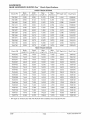
Shock Specifications
FRONT TRACK SHOCKS
Shock PN
Body
Length (in)
Shaft
Length (in)
Max.
Length (in)
Max.
Travel (in)
IFP Depth (in)
Shaft Part#
7041294
5.050
5.350
10.470
2.850
0.544
1500040
7041386
8.955
9.125
18.150
6.375
1.140
1500068
7041402
5.430
5.570
11.070
3.070
0.586
1500153
7041413
5.050
5.350
10.470
2.850
0.544
1500040
7041493
5.430
5.570
11.070
3.070
0.590
1500153
7041507
5.330
6.400
11.060
3.150
4.570
1500076
7041584
5.430
5.570
11.070
3.070
0.586
1500153
7041589
5.430
5.570
11.070
3.070
0.586
1500153
7041641
5.330
5.570
10.970
3.070
0.600
1500153
7041642
5.330
5.570
10.970
3.070
0.600
1500153
7041706
5.330
5.570
10.850
3.070
0.600
1500153
7041735
5.330
5.570
10.850
3.070
0.600
1500153
REAR TRACK SHOCKS
Shock PN
Body
Length (in)
Shaft
Length (in)
Max.
Length (in)
Max.
Travel (in)
IFP Depth (in)
Shaft Part#
7041293
7.440
7.450
14.523
4.700
0.835
1500152
7041345
7.440
7.450
14.523
4.700
0.835
1500152
7041347
7.440
7.450
14.523
4.700
0.835
1500152
7041387
5.850
6.350
12.320
3.650
0.633
1500076
7041403
6.825
6.850
13.560
4.350
0.795
1500133
7041444
7.440
7.450
14.523
4.700
0.835
1500152
7041480
5.850
6.350
12.320
3.650
0.630
1500076
7041492
7.440
7.450
14.520
4.700
0.835
1500152
7041585
7.440
7.450
14.523
4.700
0.835
1500152
7041588
7.440
7.450
14.523
4.700
0.835
1500152
7041595
7.440
7.450
14.523
4.700
0.835
1500152
7041599
7.440
7.450
14.520
4.700
1.500
1500152
7041695
7.440
7.450
14.523
4.700
0.835
1500152
7041707
7.440
7.450
14.520
4.700
1.500
1500152
7041728
7.440
7.450
14.523
4.700
0.835
1500152
7041751
7.440
7.450
14.523
4.700
0.835
1500152
7041779
5.330
5.570
10.850
3.070
0.600
1500153
* IFP depth for limited build 1996 440 XCR SP with handlebar shock adjuster=4.570"
8/98
7.44
Polaris Industries Inc.
SUSPENSION
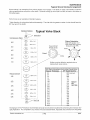
Typical Shock Valving Arrangement
Shown below is an example of how valving stacks are arranged. The tables on page 7.46 contain production
valving specifications and piston orifice sizes. Optional valving (by shock part number) is listed in the tables on
following pages.
Parts in box are an example of standard valving.
*Note direction of valve piston before disassembly. The side with the greater number of slots should face the
IFP (nut end of the shaft).
Typical Valve Stack
standard Valving
UV
~
Compression Stack
shaft End
~---------,
I
I
I
@
.800x .010
:
@
.900x .010
:
~
I
~
:
II~
~
:1®
I®
1.00x.010
Toward Shaft
(Fewer slots)
I
I
'
1.300 X .01 0
:
I
Piston*
I
1.300 X .012 I
I
I
I
I
I
0
0~
0
Orifice must be drilled to required size on
replacement valve pistons.
I
:
•
Orifice
I
I
I
I
I
I
Rebound Stack
Slots'-....
I
1.100x.010 I
I
II
Piston Orientation
Side with greater# of
slots must face nut end
(Toward nut 9,. IFP)
IFP Deoth Adjustment For Limited Travel Setup
Spacer Thickness
IFP Depth Modifier
®
@)
II~
~
I
I
~
I~
: @
I
1
1.250x.010
1.100x.010
1.000x.010
.900x.010
I
I
I
.800x.010
~
:>
~
.25
.50
.75
1.0
1.25
1.50
1.75
2.00
2.25
2.50
2.75
3.00
3.25
3.50
3.75
4.00
4.25
4.50
4.75
5.00
.7oox.o1o
L _________
j
I
NutEnd
.029 (Subtract)
.058
.088
.117
.146
.175
Spacer
.204
PN
.234
5431355
.263
.292
.321
.350
.380
.409
.438
.467
.496
.526
.555
.584
Changing oil on Fox™ Shocks is recommended annually and should be included when performing end of season storage preparation. For competition use, shocks should be disassembled, inspected and serviced more frequently.
Polaris Industries Inc.
7.45
8/98
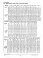
SUSPENSION
1997-1999 Production Valving Listed By Shock Part Number
7041385
IFS
7041494
IFS
7041536
IFS
7041537
IFS
7041540
IFS
7041545
IFS
7041593
IFS
7041692
IFS
7041697
IFS
N/A
N/A
N/A
N/A
1.250x.010
.800x.008
1.250x.010
.700x.008
N/A
N/A
N/A
.800x.008
0.700X.008
N/A
N/A
N/A
N/A
N/A
6C
N/A
N/A
N/A
1.250x.010
7C
N/A
N/A
1.250x.010
.900x.010
.900x.01 0
5C
0.800X.008
.800x.010
.800x.008
.800x.008
.800x.008
.800x.008
.800x.010
1.000x.010
1.000x.008
4C
0.900X.008
.900x.010
.900x.008
.900x.008
.900x.008
.900x.008
.900x.010
1.100x.008
1.100x.008
3C
1.000X.008
1.000x.01 0
1.00x.008
1.000x.008
1.000x.010
1.000x.008
1.000x.01 0
1.300x.01 0
1.300x.008
2C
1.100X.008
1.00x.010
1.1 OOx.008
1.100x.008
1.100x.008
1.100x.008
1.100x.01 0
1.000x.006
1.000x.006
1C
1.300X.008
1.300x.010
1.300x.010
1.300x.008
1.300x.010
1.300x.010
1.300x.01 0
1.300x.008
1.300x.008
0.078
0.081
0.078
0.078
0.078
0.078
0.081
0.081
0.086
1R
1.250X.008
1.250x.01 0
1.250x.010
1.250x.008
1.250x.015
1.250x.010
1.250x.010
1.250x.010
1.250x.01 0
Shock PN
8C
Compress.
Stack
Orifice
Rebound
Stack
2R
1.100X.008
1.1 00x.008
1.1 00x.010
1.1 00x.008
1.100x.012
1.1 00x.01 0
1.1 00x.008
1.100x.01 0
1.1 OOx.OO
3R
1.000X.008
1.000x.008
1.000x.01 0
1.000x.008
1.000x.010
1.000x.01 0
1.000x.008
1.000x.008
1.000x.OOb
4R
0.900X.008
.900x.008
.900x.010
.900x.008
.900x.008
.900x.010
.900x.008
.900x.008
.900x.008
5R
0.800X.008
.800x.008
.800x.008
.800x.008
.800x.008
.800x.008
.800x.008
.800x.800
.800x.008
6R
0.700X.008
.700x.008
.700x.008
.700x.008
N/A
.700x.008
.700x.008
.700x.008
.700x.008
7041507
Front Track
7041584
Front Track
7041589
Front Track
7041641
Front Track
7041642
Front Track
7041706
Front Track
7041779
Front Track
7041735
Front Track
N/A
N/A
N/A
N/A
1.250x.010
N/A
1.250x.01 0
1.250x.010
.700x.010
N/A
N/A
N/A
7C
.700x.010
.800x.010
.700x.010
.800x.012
6C
1.250x.01 0
.900x.010
.800x.010
1.250x.01 0
.800x.010
.900x.012
.800x.010
.900x.012
5C
.800x.008
1.000x.012
.900x.010
.800x.008
.900x.010
1.000x.012
.900x.010
1.00x.010
4C
.900x.012
1.1 00x.012
1.000x.01 0
.900x.012
1.000x.010
1.100x.01 0
1.000x.010
1.1 00x.01 0
3C
1.000x.012
1.300x.012
1.1 00x.01 0
1.000x.012
1.100x.010
1.300x.012
1.100x.010
1.300x.012
2C
1.100x.012
.900x.006
1.250x.012
1.100x.012
1.250x.012
1.000x.006
1.250x.012
.900x.008
1.300x.012
1.300x.010
1.300x.012
1.300x.010
Shock PN
8C
Compress.
Stack
1C
1.300x.012
1.300x.008
1.300x.012
1.300x.012
0.075
0.075
0.075
0.075
0.075
0.075
0.076
0.076
1.250x.01 0
1.250x.01 0
1.250x.01 0
1.250x.01 0
1.250x.01 0
1.250x.010
1.250x.010
1.250x.012
Orifice
1R
Rebound
Stack
1.100x.01 0
1.1 oox.010
1.100x.010
1.1 00x.01 0
1.100x.010
1.100x.010
1.100x.010
1.000x.010
1.000x.012
1.000x.010
1.000x.012
1.000x.01 0
1.000x.012
1.000x.010
4R
.900x.010
.900x.010
.900x.010
.900x.010
.900x.01 0
.900x.01 0
.900x.010
.900x.01 0
5R
.800x.01 0
.800x.01 0
.800x.010
.800x.010
.800x.01 0
.800x.01 0
.800x.010
.800x.010
6R
.700x.01 0
.700x.010
.700x.01 0
.700x.01 0
.700x.010
.700x.010
.700x.010
.700x.010
7041492
Rear Track
N/A
N/A
1.250x.010
N/A
7C
.900x.010
1.250x.010
8C
7041585
Rear Track
7041595
Rear Track
7041599
Rear Track
7041695
Rear Track
7041707
Rear Track
7041728
Rear Track
N/A
N/A
1.250x.01 0
1.250x.010
1.250x.01 0
.700x.008
1.250x.010
.900x.010
.900x.012
.900x.012
N/A
N/A
7041588
Rear Track
6C
0.700X.006
1.100x.012
.900x.010
.800x.008
.900x.010
1.000x.012
1.000x.008
1.000x.012
.900x.010
5C
0.800X.006
1.100x.015
1.000x.010
.900x.010
1.000x.012
1.1 00x.015
1.000x.012
1.100x.015
1.000x.01 0
4C
0.900X.006
1.250x.010
1.100x.015
1.000x.008
1.100x.015
1.250x.010
1.100x.015
1.250x.01 0
1.100x.010
3C
1.000X.006
1.300x.015
1.300x.015
1.1 OOx.008
1.300x.015
1.300x.015
1.300x.015
1.300x.012
1.250x.012
1.000x.006
.900x.006
1.300x.008
2C
1.1 OOX.006
1.000x.006
1.000x.006
1.250x.008
.900x.012
1.000x.006
.900x.012
1C
1.300X.006
1.300x.012
1.300x.01 0
1.300x.008
1.300x.012
1.300x.012
1.300x.012
1.300x.012
0.067
0.072
0.086
0.078
0.086
0.072
0.086
0.072
0.063
1R
1.250X.010
1.250x.010
1.250x.012
1.250x.012
1.250x.012
1.250x.010
1.250x.012
1.250x.010
1.250x.015
Orifice
Rebound
Stack
1.1 00x.01 0
1.000x.010
7041480
Rear Track
Shock PN
Compress.
Stack
2R
3R
2R
1.100X.010
1.1 OOx.012
1.100x.012
1.100x.012
1.1 00x.012
1.100x.012
1.100x.012
1.250x.01 0
1.250x.012
3R
1.000X.01 0
1.000x.012
1.000x.012
1.000x.012
1.1 00x.012
1.000x.012
1.100x.012
1.100x.012
1.1 oox.012
4R
0.900X.010
.900x.012
.900x.012
.900x.012
.900x.012
.900x.012
1.000x.012
1.000x.012
1.000x.010
5R
0.800X.01 0
.800x.012
.800x.012
.800x.012
.800x.012
.800x.012
.900x.012
.900x.012
.900x.01 0
6R
0.700X.010
.700x.012
.700x.012
.700x.012
.700x.012
.700x.012
.800x.012
.800x.012
.800x.01 0
N/A =Not Applicable
8/98
7.46
Polaris Industries Inc.
SUSPENSION
1999 Optional Valving Listed By Shock Part Number
1999 500 XC SP I 600 XC SP I 700 XC SP
LIGHT
Shock PN
Compression Stack
7041697
IFSX-10
CRC
7041735
Front Track
X 10
7041728
Rear Track
X10
7041697
IFS X-10
CRC
7041735
Front Track
X 10
8C
NIA
NIA
0.8x.010
1.25x.010
7C
0.8x.008
0.8x.010
NIA
NIA
0.9x.012
0.8x.012
6C
0.9x.008
0.9x.010
NIA
1.0x.012
0.9x.015
5C
1.0x.006
1.0x.008
NIA
1.1x.010
1.0x.012
4C
1.1x.008
1.1x.008
NIA
1.3x.010
1.1x.012
ro
3C
1.3x.008
1.3x.008
NIA
1.0x.006
1.3x.012
_o
2C
1.0x.008
0.9x.008
NIA
1.25x.008
0.9x.006
1C
1.3x.008
1.3x.008
NIA
1.3x.008
1.3x.01 0
7041728
Rear Track
X10
LD
m
C\J
C\J
I'C\J
,__
(l)
E
:J
z
t
C\l
.086
.076
NIA
.086
.076
1R
1.25x.008
1.25x.01 0
NIA
1.25x.010
1.25x.012
2R
1.1x.008
1.1x.010
NIA
1.1x.010
1.1x.012
3R
1.0x.008
1.0x.01 0
NIA
1.0x.008
1.0x.010
4R
0.9x.008
0.9x.01 0
NIA
0.9x.008
0.9x.010
5R
0.8x.008
0.8x.010
NIA
0.8x.008
0.8x.012
6R
0.7x.008
0.7x.010
NIA
NIA
0.7x.010
Orifice
Rebound
Stack
HEAVY
0..
~
(l)
(l)
(f)
1999 440 XCR
HEAVY
LIGHT
Shock PN
Compression Stack
7041692
IFS X-10
CRC
7041706
Front Track
X 10
7041707
Rear Track
X 10
7041692
IFSX-10
CRC
7041706
Front Track
X 10
7041707
Rear Track
X10
8C
1.25X.008
1.25x.01 0
1.25x.010
1.25X.010
1.25x.010
1.25x.010
7C
0.8X.008
0.8x.010
0.8x.010
0.8X.01 0
0.8x.012
0.9x.012
6C
0.9X.01 0
0.9x.010
0.9x.012
0.9X.012
0.9x.015
1.0x.012
5C
1.0X.008
1.0x.012
1.0x.01 0
1.0X.01 0
1.0x.015
1.1x.015
4C
1.1X.008
1.1x.008
1.1x.01 0
1.1X.010
1.1x.012
1.25x.012
3C
1.3X.008
1.3x.01 0
1.3x.01 0
1.3X.012
1.3x.012
1.3x.015
2C
1.0X.008
0.9x.008
1.0x.008
1.0X.006
1.0x.006
1.0x.006
1C
1.3X.008
1.3x.008
1.3x.008
1.3X.010
1.3x.01 0
1.3x.012
0.081
.075
.072
0.081
.075
.072
1R
1.25X.01 0
1.25x.010
1.25x.010
1.25X.010
1.25x.012
1.25x.012
2R
1.1X.008
1.1x.010
1.1x.012
1.1X.010
1.1x.012
1.25x.012
3R
1.0X.008
1.0x.008
1.0x.012
1.0X.008
1.0x.01 0
1.1x.012
4R
0.9X.008
0.9x.008
0.9x.012
0.9X.008
0.9x.010
1.0x.012
5R
0.8X.008
0.8x.008
0.8x.012
0.8X.008
0.8x.01 0
0.9x.012
6R
0.7X.008
0.7x.01 0
0.7x.012
0.7X.008
0.7x.010
0.8x.012
7R
NIA
NIA
NIA
NIA
NIA
0.7x.012
Orifice
Rebound
Stack
Polaris Industries Inc.
7.47
8/98
SUSPENSION
1999 Optional Valving Listed By Shock Part Number
1999 700 XCR I 800 XCR
LIGHT
Shock PN
Compression Stack
7041540
IFS X-10
7041779
Front Track
X10
7041695
Rear Track
X10
7041540
IFS X-10
7041779
Front Track
X 10
7041695
Rear Track
X 10
8C
N/A
N/A
N/A
N/A
N/A
N/A
7C
N/A
0.7x.010
1.25X.010
N/A
0.7x.010
1.25X.010
6C
N/A
0.8x.008
0.9X.008
N/A
0.8x.012
0.9X.012
5C
0.8X.008
0.9x.008
1.0X.008
0.8X.010
0.9x.012
1.0X.010
4C
0.9X.008
1.0x.008
1.1X.010
0.9X.010
1.0x.012
1.10X.015
3C
1.0X.008
1.1x.01 0
1.3X.012
1.0X.012
1.1x.015
1.3X.015
2C
1.1X.006
1.25x.01 0
0.9X.012
1.1X.012
1.25x.012
0.9X.008
1C
1.3X.008
1.3x.010
1.3X.010
1.3X.012
1.3x.012
1.3X.012
0.078
.076
0.086
0.078
.076
0.086
1R
1.25X.012
1.25x.01 0
1.25X.012
1.25X.015
1.25x.012
1.25X.012
2R
1.1X.012
1.1x.008
1.1X.010
1.1X.012
1.1 x.012
1.10X.012
3R
1.0X.012
1.0x.010
1.0X.01 0
1.0X.012
1.0x.015
1.0X.012
4R
0.9X.010
0.9x.010
0.9X.010
0.9X.01 0
0.9x.012
0.9X.012
5R
0.8X.008
0.8x.010
0.8X.01 0
0.8X.008
0.8x.01 0
0.8X.012
6R
0.7X.008
0.7x.01 0
0.7X.010
0.7X.008
0.7x.01 0
0.7X.012
7R
N/A
N/A
N/A
N/A
N/A
N/A
Orifice
Rebound
Stack
HEAVY
Refer to the appropriate parts manual for a complete listing of Fox shock parts. Fox, Registered Trademark of
FOX Shox.
Shock Travel Limiting Spacer (1/4") - Part Number 5431355
Valve Washer Part Numbers
Part No.
1500052
1500050
1500049
1500048
1500053
1500054
1500055
1500030
1500051
1500031
1500032
1500033
1500028
1500029
1500062
1500026
1500027
1500045
....
....
....
....
....
....
Part No.
1500046 ...
1500047 ...
1500044 ...
1500079 ...
1500078 ...
1500060 ...
1500059 ...
1500058 ...
1500057 ...
1500056 ...
1500087 . . .
1500086 ...
1500085 ...
1500084 ...
1500083 ...
1500082 ...
1500081 ...
Description
1.300 X 0.006
1.250 X 0.006
1.100x0.006
1.000 X 0.006
0.900 X 0.006
0.800 X 0.006
0.700 X 0.006
1.300 X 0.008
1.250 X 0.008
1.100 X 0.008
1.000 X 0.008
0.900 X 0.008
0.800 X 0.008
0.700 X 0.008
1.300x0.010
1.250x0.010
1.100x0.010
1.000x0.010
Description
0.900 X 0.010
0.800 X 0.010
0. 700 X 0.010
1.300 X 0.012
1.250 X 0.012
1.100 X 0.012
1.000 X 0.012
0.900 X 0.012
0.800 X 0.012
0.700 X 0.012
1 .300 X 0.015
1.250 X 0.015
1.100 X 0.015
1.000 X 0.015
0.900 X 0.015
0.800 X 0.015
0.700 X 0.015
Note: Subtract .029" from IFP depth for each 1/4 inch spacer added to the shock damper rod for limiting.
For example: If standard (full shock travel) IFP depth is .835", and 6 spacers are added to reduce shock travel by
1.5 inches, multiply .029 x 6 to calculate the amount to subtract from IFP depth .
.835-.174 = .661 (± .025") New IFP Depth
8/98
7.48
Polaris Industries Inc.
SUSPENSION
Fox™ Shock Maintenance
Changing oil on Fox™ Shocks is recommended annually and should be included when performing end of season
storage preparation. This oil change is necessary to avoid any chance of corrosion which could be caused by
moisture contamination. For competition use, shocks should be disassembled, inspected and serviced more frequently.
When performing maintenance on Fox™ Shocks, use Gas Shock Recharging Kit PN 2200421. It consists of the
necessary valves, pressure gauge, and fittings to deflate and pressurize the shocks. The Body Holder Tool, Internal Floating Piston (IFP), and Shock Rod Holding Tool are not included in the Recharging Kit and must be ordered
separately. Refer to your Victor Specialty Tool catalog for part numbers.
Gas Shock Recharging Kit
PN 2200421
A
WARNING
Extreme caution should be observed while handling and working with high pressure service equipment. Wear
a face shield, safety glasses, and ear protection during service of these shocks.
Care should be observed while handling the inflater needle and pressure gauges. Maintain your equipment and
keep it in good condition. If injury should occur, consult a physician immediately.
Extreme cleanliness is of utmost importance during all disassembly and reassembly operations to prevent any
dirt or foreign particles from getting into the shocks.
Keep the parts in order as they are disassembled. Note the direction and position of all internal parts for reassembly.
Bleed Screw
Ref.#
Qty.
Description
1
1
Pressure Valve
2
2
0-Ring
3
1
Retaining Ring
4
1
Spring Retainer Body
5
2
0-Ring
6
1
Piston Ring (Floating)
7
1
Piston Ring (Damping)
8
1
Spring Retainer, Slotted
Polaris Industries Inc.
Internal Floating
Piston (IFP)
3
Shock Body
8
7.49
8/98
SUSPENSION
Fox™ Shock Maintenance
Disassembly
1.
Remove spring and bushings from shock eyes.
Thoroughly wash shocks in a parts washer or with
soap and water to remove dirt and other debris. Dry
thoroughly with compressed air. Position and clamp
body cap of shock in soft jaws (aluminum or brass) of
vise. Remove Allen screw from pressure valve.
2.
With valve outlet pointed in a safe direction, insert red
tip of safety needle assembly into recess in shock
pressure valve. Depress safety pin on safety needle
and push gauge and needle assembly slowly toward
shock, inserting needle. Be sure to push needle
completely into shock valve. Release nitrogen in a
safe direction away from everyone by turning
T-handle clockwise (if equipped) or by depressing
Schrader valve pin.
I
CAUTION:
I
It is possible for some residual pressure to remain in the
shock regardless of the gauge reading. Always completely remove valve from body cap before further disassembly of shock.
3.
Remove valve and sealing 0-ring from body cap.
4.
Extend shock shaft by pulling up on shock eyelet.
Using a 1" (25 mm) wrench, loosen shaft bearing cap.
8/98
7.50
Polaris Industries Inc.
SUSPENSION
Fox™ Shock Maintenance
Disassembly, Cont.
5.
If body of shock starts to unscrew from body, tighten
and try again. To keep body from turning, it may be
necessary to use Body Clamp Tool clamped lightly
around body in soft jaws of vise as shown.
NOTE: Position body clamp at least 1 1/2" below bearing
cap.
Shock Body Clamp Tool
PN 2871071
6.
Pull shock rod and piston straight out to avoid seal or
valve damage. Be prepared to catch piston ring
when removing the damper rod/valve piston.
7.
Remove shock from vise and dispose of used oil
properly in suitable container. Set shock body aside.
8.
Mount damper rod in soft-jawed vise as shown.
Loosen valve nut and clean the valve piston and
valving washers with electrical contact cleaner. Dry
thoroughly with compressed air. Tighten nut and
torque to 12ft. lbs. (1.66 kg-m).
Valve Nut Torque 12ft. lbs. {1.66 kg-m)
Polaris Industries Inc.
7.51
8/98
SUSPENSION
Fox™ Shock Maintenance
9.
If bearing cap and/or seals are to be replaced,
remove nut, washer, and valve piston with valving
washers and set aside. Keep washers in order and
note orientation of slots in piston for proper
re-installation. The side with the greater number of
slots must face the damper rod nut (toward IFP).
Seal Replacement
1.
Remove bearing cap from damper rod. Inspect
seals, o-ring, and bushing inside cap. Inspect cap
0-ring and replace if torn or damaged.
2.
Using a small screwdriver or scribe pry upper seal,
main seal, and 0-ring out of bearing cap. Use care to
avoid scratching the seal cavity.
3.
Clean seal cavity and inspect bushing for wear or
damage and replace bearing cap if necessary.
4.
Lubricate new seals and 0-ring with Polaris shock oil
and install. Be sure the seals are seated completely
in the seal cavity.
5.
Inspect jounce bumper (where applicable) and
replace if damaged.
6.
Inspect damper rod for nicks, scratches or abrasion.
Install bearing cap and thick backing washer on
damper rod. Install compression valve washer stack
in same order as disassembly. Install valve piston
with greater number of slots facing damper rod nut
(toward IFP). Install rebound stack, washer, and a
new nut. Torque nut to 12ft. lbs.
Valve Nut Torque -
12ft. lbs. (1.66 kg-m)
8/98
7.52
Polaris Industries Inc.
SUSPENSION
Fox™ Shock Maintenance
Seal Replacement, Cont.
7.
Inspect valve piston ring for wear. The outer surface
of the ring should be even in color. Set aside damper
rod assembly for reinstallation.
8.
Position shock in vise with Body Clamp Tool
positioned as shown. Clean body clamp tool before
installing.
Shock Body Clamp Tool
PN 2871071
9.
Using an open end or large adjustable wrench,
unscrew the body cap from the body.
10. Inspect 0-ring in body cap for damage.
11. Note location of Allen screw in internal floating piston
(IFP) for reassembly in body tube. Remove IFP
through body cap end (external threaded end) using
IFP tool. Be prepared to catch piston ring and piston
as it comes out. Remove Allen screw from center of
piston. Inspect bleeder screw 0-ring and IFP sealing
0-ring for wear or damage. Replace 0-rings upon
reassembly.
12. Carefully clean all parts thoroughly with electrical
contact cleaner or solvent and dry with compressed
air. Inspect shock body for scratches or wear.
Polaris Industries Inc.
7.53
8/98
SUSPENSION
Fox™ Shock Maintenance
Reassembly
1.
Install bleeder screw in IFP until 0-ring is lightly
seated.
NOTE: Bleeder screw must be positioned toward body
cap (externally threaded) end of shock body.
2.
Compress flexible piston ring around valve piston
and install piston into shock body.
3.
Screw in bearing cap by hand until 0-ring is fully
seated.
4.
Invert shock and mount bearing cap flats lightly in
vise. Caution: Be sure damper rod is fully extended.
8/98
7.54
Polaris Industries Inc.
SUSPENSION
Fox™ Shock Maintenance
Reassembly, Cont.
5.
Fill with shock fluid to approximately 1" (2.54cm) from
end of body.
6.
Install body cap until 0-ring is lightly seated.
7.
Mount shock in vise by top eyelet as shown. Support
shock and strike body cap end 2-3 times with a soft
faced hammer to remove all air trapped inside the
valve piston. Allow shock to stand for 3-5 minutes.
Do not over-tighten vise or bearing cap may be damaged
8.
Unscrew body cap and remove.
9.
Remove IFP bleeder screw.
10. Set IFP tool to specified depth with a dial caliper as
shown.
IFP Tool PN 2871351
Polaris Industries Inc.
7.55
8/98
SUSPENSION
Fox™ Shock Maintenance
Reassembly, Cont.
11. Place a shop towel over the end of IFP tool and slowly
push IFP to specified depth.
12. With the IFP set and the bleeder screw removed,
slowly stroke shock to force air through piston
oriface. Move the shock body slowly to prevent
aeration of the oil. Allow all air to purge throught the
bleeder screw hole.
13. Install the bleeder screw with a new 0-ring and
tighten securely using the flats on the tool to prevent
the IFP from turning. Pour out excess oil. It is not
necessary to completely clean all oil from the
nitrogen chamber, a small amount of oil will lubricate
the IFP. Verify the proper IFP depth to within± .025"
(.63mm) with a dial caliper. Be sure to measure to the
flat portion of the lFP, not to the tapered outer edge.
14. Reinstall body cap with a new 0-ring and tighten by
hand. Mount shock with body cap end down in the
soft jaws of a vise. Torque bearing cap to 8-10ft. lbs.
(1.1 0-1.38 kg/m). This will also tighten the body into
the body cap.
I CAUTION: I
Do not over tighten or damage to the bearing may result.
Bearing Cap Torque -
8-10 ft.lbs. (1.10-1.38 kg-m)
8/98
7.56
Polaris Industries Inc.
SUSPENSION
Fox™ Shock Maintenance
Reassembly, Cont.
15. Install pressurizing valve with new 0-ring and tighten
securely.
16. Set the nitrogen tank pressure regulator to 200 - 205
PSI.
17. Insert the Fox™ Safety Needle and charge with
nitrogen to 200 PSI. Pull the needle straight outward
and remove from the pressurizing valve while holding
the pressure hose on the fitting. Do not insert the
needle again to check pressure as the volume inside
the gauge will reduce pressure in the shock.
18. As a final check, push the damper rod through a full
stroke. The damper rod must bottom out at full travel,
and then slowly rise to full extension.
Shaft
movement must be smooth and consistent
throughout the entire compression and rebound
stroke, without binding or loss of damping.
Polaris Industries Inc.
7.57
8/98
SUSPENSION
Fox™ Shock Maintenance
Reassembly, Cont.
19. To check for leaks, submerge the shock in water and
look for bubbles or oil seepage around the bearing
and body caps.
20. When reinstalling shocks on the machine, torque
only to required specifications. If the shock is over
tightened it will not pivot, possibly resulting in damage
to shaft and seals.
21. When installing IFS shocks, tighten top mount first.
Pivot shock body into lower mount and determine if
spacer washers are necessary to prevent twist or
side loading of shock. Suspension assemblies
should always be moved through entire travel without
springs to verify free movement and proper
alignment of all components.
Shock Eyelet Replacement
Top Shock Eyelet
b
Damper Rod Holding
nn/ol PN 2871352
Y~
1
1
~
If shock eyelet is removed for damper rod replacement, clean threads
of eyelet and damper rod thoroughly with Loctite"" Primer N.
Apply Loctite"" 262 to threads before assembly.
I
I
8/98
7.58
Polaris Industries Inc.
SUSPENSION
Polaris Position Sensitive Shock (PSS)
COMPRESSION STROKE
INITIAL
COMPRESSION
STROKE
BASIC
PRINCIPAL #1
For pi stan travel
as shown, oil
must get from
this side of ---++-++-piston to this
side of piston.
BASIC
PRINCIPAL #2
Oil must either
go through
piston valving,
or into outer
chamber
(bypass).
On initiation of
compression
stroke, all flow
occurs through
the piston only.
No bypass flow
is available in
this travel range.
END-COMPRESSION
STROKE
MID-COMPRESSION
STROKE
PISTON
MOVEMENT
No bypass
available.
Increased
compression
damping for
anti-bottom-out.
PISTON
MOVEMENT
Maximum
bypass of oil
middle of
compression
stroke.
PISTON
MOVEMENT
Lowest
compression
damping
Very plush ride.
Valves on this
side of piston
flex open to
regulate flow.
Polaris Industries Inc.
7.59
8/98
SUSPENSION
Polaris Position Sensitive Shock (PSS)
REBOUND STROKE
INITIAL
REBOUND
STROKE
MID-REBOUND
STROKE
END-REBOUND
STROKE
Valves on this
side of piston
flex open to
regulate flow.
No bypass flow
is available in
this travel
range.
Rebound bypass
is limited to
these holes ~-..,..,
Flow is restricted
on hole(s)
covered by one
way check valve.
PISTON
MOVEMENT
Maximum
bypass of oil
into outer
chamber at
this stage.
t
PISTON
MOVEMENT
PISTON
MOVEMENT
No bypass
available
into outer
chamber.
Increased
rebound
damping for
anti-top-out.
8/98
7.60
Polaris Industries Inc.
SUSPENSION
Polaris Position Sensitive Shock (PSS)
SHOCK VALVJNG
COMPRESSION:
7.450"
1.
2.
3.
4.
5.
6.
1.300 X .008
.900 X .006
1.250 X .012
1.100 X .010
1.000 X .010
.900 X .010
REBOUND:
1.
2.
3.
4.
5.
6.
/
1 .250 X .015
1.250 X .012
1 .1 00 X .012
1.000 X .010
.900 X .010
.800 X .010
/
A
B
//
//
/
/
PISTON ORIFICE: .063
/
/
/
c
D
SHOCK DESIGN DETAILS:
E
Travel
Extended Length
Compressed Length
IFP Depth
Bearing
Nitrogen Pressure
4.70"
14.52"
9.82"
.835"
1.15"
200 PSI
BY-PASS HOLE DETAILS:
LOCATION
QUANTITY
CHECK VALVE
DIAMETER
A.
B.
C.
D.
E.
1
3
1
NO
NO
NO
YES
NO
0.0787"
0.0787"
0.0787"
0.0787"
0.0787"
Polaris Industries Inc.
1.80
2.00
3.50
4.25
4.50
2
1
7.61
8/98
SUSPENSION
Position Sensitive Shock Maintenance
Disassembly
1.
Remove bushings from body cap. Thoroughly wash
shock in a parts washer or with soap and water to
remove dirt and other debris. Dry thoroughly with
compressed air. Position and clamp body cap of
shock in soft jaws (aluminum or brass) of vise, body
cap down (as shown).
2.
Remove Allen screw from pressure valve.
3.
With valve outlet pointed in a safe direction, insert red
tip of safety needle assembly into recess in shock
pressure valve. Depress safety pin on safety needle
and push gauge and needle assembly slowly toward
shock, inserting needle. Be sure to push needle
completely into shock valve. Release nitrogen in a
safe direction away from everyone by turning
T-handle clockwise (if equipped) or by depressing
Schrader valve pin.
·. CAUTION;
I
It is possible for some residual pressure to remain in the
shock regardless of the gauge reading. Always completely remove valve from body cap before further disassembly of shock.
4.
Remove valve and sealing 0-ring from body cap.
5.
Extend shock shaft by pulling up on shock eyelet.
Using a 1" (25 mm) wrench, loosen shaft bearing cap.
8/98
7.62
Polaris Industries Inc.
SUSPENSION
Position Sensitive Shock Maintenance
Disassembly, Cont.
6.
If bearing comes loose first, unscrew bearing from
body and remove the shaft assembly from the body.
Pull shock rod and piston straight out to avoid seal or
valve damage. Be prepared to catch piston ring
when removing the damper rod/valve piston.
7.
Remove shock from vise and dispose of used oil
properly in suitable container.
8.
Clamp the exposed portion of the shock body in a
vice using shock body clamp tool, body cap up. DO
NOT clamp on bypass sleeve or damage to the shock
will occur.
Shock Body Clamp Tool
PN 2871071
9.
Remove the body cap
Polaris Industries Inc.
7.63
8/98
SUSPENSION
Position Sensitive Shock Maintenance
Disassembly, cont.
10. Remove IFP
11. Remove bypass Sleeve.
1.
If body cap comes loose first, reclamp shock in vice,
gripping on bearing flats with the body cap up.
2.
Remove body cap.
NOTE: Make sure bypass sleeve remains in contact with
collar during this procedure. Oil will spill if bypass sleeve
separates from collar.
8/98
7.64
Polaris Industries Inc.
SUSPENSION
Position Sensitive Shock Maintenance
Disassembly, Cont.
3.
Remove IFP and dispose of shock oil properly.
4.
Remove bypass sleeve and clamp shock body in vise
using body clamps.
5.
Unscrew bearing from body and remove shaft
assembly from body. Be prepared to catch piston
ring.
6.
Follow procedures in Fox"' shock maintenance
section for inspection, cleaning, and valving if
needed.
Polaris Industries Inc.
7.65
8/98
SUSPENSION
Position Sensitive Shock Maintenance
Assembly
1.
Compress piston ring and insert shaft assembly into
shock body.
2.
Inspect bypass sleeve for burrs, dents, or other
physical damage.
3.
Lube collar 0-ring and replace bypass sleeve over
body. Be sure of a snug fit - do not pinch or cut 0-ring.
4.
Clamp eyelet of shock in the vise body up. Fill shock
and bypass sleeve through shock body. Oil should
cover all bypass holes. Fill to approximately one inch
(2.54cm) from end of body.
8/98
7.66
Polaris Industries Inc.
SUSPENSION
Position Sensitive Shock Maintenance
Aassembly, Cont.
5.
Cycle shock through the first couple inches of travel
to release trapped air. Take care not to spill oil over
the bypass sleeve or introduce air through bypass
holes.
6.
Ensure that the shaft is fully extended and set the IFP
to the proper depth. Remove IFP bleeder screw to be
sure no air is trapped under the IFP. Install IFP.
IFP Depth:
.835" (21.2mm)
7.
Replace the IFP bleed screw with a new 0-ring and
tighten securely. Hold shock fully extended and fill oil
in bypass sleeve to the top.
8.
Replace the body cap. Oil will drain over the edge of
the bypass sleeve until the 0-ring seals.
Polaris Industries Inc.
7.67
8/98
SUSPENSION
Position Sensitive Shock Maintenance
9.
Once the body cap 0-ring seals, re-position the
shock in the vice by clamping on the body cap with
the shaft up.
10. Continue to tighten the body cap utilizing flats on the
bearing. Torque cap to 55 ft lbs. Install pressure
valve with new 0-ring and tighten securely.
Pressurize shock to 200 psi.
Body Cap Torque
55 ft. lbs.
8/98
7.68
Polaris Industries Inc.
SUSPENSION
Suspension Troubleshooting - WideTrak Style
Problem
Solution
Rear suspension bottoms too easily
-Increase torsion spring preload
-Increase rear shock compression valving by turning
screw clockwise (if equipped with optional Indy Select
shock)
-Install overload kit PN 2871042 for extreme use
Rides too stiff in rear
-Check for binding suspension shafts and grease all pivot
points
-Decrease torsion spring preload adjustments
-Decrease rear shock compression valving by turning
screw counterclockwise (if equipped with optional Indy
Select shock)
-Check for proper track tension
Machine darts from side to side
-Make sure skis are aligned properly (straight
forward with rider on machine)
-Make sure spindles and all steering components are
free turning
-Make sure skags are straight on skis
-Check hi-fax and replace if worn
-Reduce ski pressure:
•Increase front track spring preload
•Reduce IFS spring preload if shims have
been added
•Reduce rear torsion spring preload
Front end pushes
-Check for worn skags
-Check for binding suspension shafts and grease all pivot
points
-Increase IFS spring preload by adding shims
Steering is heavy
-Check ski alignment
-Check skags and skis for damage
-Reduce ski pressure:
•Increase front track spring preload
•Reduce IFS spring preload if shims have
been added
•Reduce rear torsion spring preload
Setting up for deep snow operation
-Change worn hi-fax
-Lower front and rear torque arms (see Performance section at the back of this manual)
Polaris Industries Inc.
7.69
8/98
SUSPENSION
Suspension Troubleshooting - XTRA Lite Style
Problem
Solution
Rear suspension bottoms too easily
-Increase torsion spring preload
-Increase rear shock compression valving by turning
screw clockwise (if equipped with optional Indy Select
shock)
Rides too stiff in rear
-Check for binding suspension shafts and grease all pivot
points
-Decrease torsion spring preload adjustments
-Decrease rear shock compression valving by turning
screw counterclockwise (if equipped with optional Indy
Select shock)
Machine darts from side to side
-Make sure skis are aligned properly (straight
forward with rider on machine)
-Make sure spindles and all steering components are
free turning
-Make sure skags are straight on skis
-Check hi-fax and replace if worn
-Reduce ski pressure:
•Increase front track spring preload
•Reduce IFS spring preload if shims have
been added
•Reduce rear torsion spring preload
Front end pushes
-Check for worn skags
-Check for binding suspension shafts and grease all pivot
points
-Increase IFS spring preload by adding shims
Steering is heavy
-Check ski alignment
-Check skags and skis for damage
-Reduce ski pressure:
•Increase front track spring preload
•Reduce IFS spring preload if shims have
been added
•Reduce rear torsion spring preload
Setting up for deep snow operation
-Change worn hi-fax
-Lower front and rear torque arms (see Performance section at the back of this manual)
8/98
7.70
Polaris Industries Inc.
SUSPENSION
Suspension Troubleshooting- XTRA 10 Style
Problem
Solution
Rear suspension bottoms too easily
-Increase torsion spring preload
-Increase rear shock compression valving by turning
screw clockwise (if equipped with optional Indy Select
shock) or refer to optional valving on Suspension Wallchart for Fox equipped models
-Change RRSS to highest setting
Rides too stiff in rear
-Check for binding suspension shafts and grease all pivot
points
-Decrease torsion spring preload adjustments
-Decrease rear shock compression valving by turning
screw counterclockwise (if equipped with optional Indy
Select shock) or refer to optional valving on Suspension
Wallchart for Fox equipped models
-Set RRSS to lowest position or totally remove
Machine darts from side to side
-Make sure skis are aligned properly (straight
forward with rider on machine)
-Make sure spindles and all steering components are
free turning
-Make sure skags are straight on skis
-Check hi-fax and replace if worn
-Reduce ski pressure:
•Increase front track spring preload
(requires shims)
•Reduce IFS spring preload by adjusting
cam
•Reduce rear torsion spring preload
•Lengthen front limiter strap
Front end pushes
-Check for worn skags
-Check for binding suspension shafts and grease all pivot
points
-Increase IFS spring preload by adjusting cam or adding
washers
-Shorten front limiter strap
Steering is heavy
-Check ski alignment
-Check skags and skis for damage
-Reduce ski pressure:
•Increase front track spring preload
•Reduce IFS spring preload by adjusting
cam
•Reduce rear torsion spring preload
Setting up for deep snow operation
-Change worn hi-fax
-Lower rear torque arms (see Performance section at the
back of this manual)
-Increase front limiter strap length
-Based on rider preference, RRSS may be removed to
increase weight transfer
Polaris Industries Inc.
7.71
8/98
SUSPENSION
Suspension Troubleshooting - XTRA 12 Style
Problem
Solution
Rear suspension bottoms too easily
-Check to be sure FRSS block is in highest position
-Adjust torsion spring blocks to highest position
-Adjust coil over spring on front track shock to
increase preload
-Change to .421 torsion springs (PN 7041405, 7041406)
-Change to next heavier coil spring (e.g. 75/125 #/in. to
90/150 #/in.
-Change to stiffer shock valving (refer to wallchart)
-Check charge in shocks on models equipped with Fox™
shocks
Rides too stiff in rear
-Check for binding suspension shafts and grease all pivot
points
-Decrease spring preload adjustments
-Remove rear track shock spring or reduce rate of spring
(refer to wallchart)
-Change front track shock to lighter spring
-Change to lighter shock valving on models equipped
with Fox™ or Indy Select shocks (refer to wallchart)
Machine darts from side to side
-Make sure skis are aligned properly (straight
forward with rider on machine)
-Make sure spindles and all steering components are
free turning
-Make sure skags are straight on skis
Front end pushes
-Check for worn skags
-Check for binding suspension shafts and grease all pivot
points
-Increase front IFS preload
-Change FRSS to low setting or move to forwardmost
hole
Steering is heavy
-Check ski alignment
-Check skags and skis for damage
-Change FRSS to high setting
-Decrease IFS spring preload
Setting up for deep snow operation
-Rotate FRSS to lowest setting, depending upon rider
preference
-Decrease preload on front track spring
-Move FRSS to forwardmost hole
-Tighten limiter strap one hole
8/98
7.72
Polaris Industries Inc.