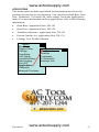
1
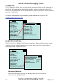
www.actoolsupply.com ENERGY AND COMFORT V e n t ilat io n Te st in g VELOCICALC® Air Velocity Meter Model 9565 Series Operation and Service Manual www.actoolsupply.com www.actoolsupply.com ____________________________________________________ TSI 9565 VelociCalc Multi Function Ventilation Air Velocity Meter _____________________________________________________ TSI 9565-A 9565 A VelociCalc Multi Function Ventilation Air Meter _____________________________________________________ TSI 9565-P 9565 P VelociCalc Multi Function Ventilation Air Meter _____________________________________________________ TSI 9565-X 9565 X VelociCalc Multi Function Ventilation Air Meter www.actoolsupply.com www.actoolsupply.com Copyright TSI Incorporated / 2011-2012 / All rights reserved. LIMITATION OF WARRANTY AND LIABILITY (effective June 2011) Seller warrants the goods sold hereunder, under normal use and service as described in the operator's manual, shall be free from defects in workmanship and material for 24 months, or if less, the length of time specified in the operator's manual, from the date of shipment to the customer. This warranty period is inclusive of any statutory warranty. This limited warranty is subject to the following exclusions and exceptions: a. Hot-wire or hot-film sensors used with research anemometers, and certain other components when indicated in specifications, are warranted for 90 days from the date of shipment; b. Pumps are warranted for hours of operation as set forth in product or operator’s manuals; c. Parts repaired or replaced as a result of repair services are warranted to be free from defects in workmanship and material, under normal use, for 90 days from the date of shipment; d. Seller does not provide any warranty on finished goods manufactured by others or on any fuses, batteries or other consumable materials. Only the original manufacturer's warranty applies; e. Unless specifically authorized in a separate writing by Seller, Seller makes no warranty with respect to, and shall have no liability in connection with, goods which are incorporated into other products or equipment, or which are modified by any person other than Seller. The foregoing is IN LIEU OF all other warranties and is subject to the LIMITATIONS stated herein. NO OTHER EXPRESS OR IMPLIED WARRANTY OF FITNESS FOR PARTICULAR PURPOSE OR MERCHANTABILITY IS MADE. WITH RESPECT TO SELLER’S BREACH OF THE IMPLIED WARRANTY AGAINST INFRINGEMENT, SAID WARRANTY IS LIMITED TO CLAIMS OF DIRECT INFRINGEMENT AND EXCLUDES CLAIMS OF CONTRIBUTORY OR INDUCED INFRINGEMENTS. BUYER’S EXCLUSIVE REMEDY SHALL BE THE RETURN OF THE PURCHASE PRICE DISCOUNTED FOR REASONABLE WEAR AND TEAR OR AT SELLER’S OPTION REPLACEMENT OF THE GOODS WITH NON-INFRINGING GOODS. TO THE EXTENT PERMITTED BY LAW, THE EXCLUSIVE REMEDY OF THE USER OR BUYER, AND THE LIMIT OF SELLER'S LIABILITY FOR ANY AND ALL LOSSES, INJURIES, OR DAMAGES CONCERNING THE GOODS (INCLUDING CLAIMS BASED ON CONTRACT, NEGLIGENCE, TORT, STRICT LIABILITY OR OTHERWISE) SHALL BE THE RETURN OF GOODS TO SELLER AND THE REFUND OF THE PURCHASE PRICE, OR, AT THE OPTION OF SELLER, THE REPAIR OR REPLACEMENT OF THE GOODS. IN THE CASE OF SOFTWARE, SELLER WILL REPAIR OR REPLACE DEFECTIVE SOFTWARE OR IF UNABLE TO DO SO, WILL REFUND THE PURCHASE PRICE OF THE SOFTWARE. IN NO EVENT SHALL SELLER BE LIABLE FOR LOST PROFITS OR ANY SPECIAL, CONSEQUENTIAL OR INCIDENTAL DAMAGES. SELLER SHALL NOT BE RESPONSIBLE FOR INSTALLATION, DISMANTLING OR REINSTALLATION COSTS OR CHARGES. No Action, regardless of form, may be brought against Seller more than 12 months after a cause of action has accrued. The goods returned under warranty to Seller's factory shall be at Buyer's risk of loss, and will be returned, if at all, at Seller's risk of loss. www.actoolsupply.com www.actoolsupply.com Buyer and all users are deemed to have accepted this LIMITATION OF WARRANTY AND LIABILITY, which contains the complete and exclusive limited warranty of Seller. This LIMITATION OF WARRANTY AND LIABILITY may not be amended, modified or its terms waived, except by writing signed by an Officer of Seller. Service Policy Knowing that inoperative or defective instruments are as detrimental to TSI as they are to our customers, our service policy is designed to give prompt attention to any problems. iv www.actoolsupply.com www.actoolsupply.com CONTENTS CHAPTER 1 UNPACKING AND PARTS IDENTIFICATION............. 1 CHAPTER 2 SETTING-UP ................................................................. 3 Supplying Power to the Model 9565 Series.................................... 3 Installing the Batteries ............................................................... 3 DIP Switch Settings ................................................................... 3 Using the AC Adapter ................................................................ 4 Connecting Ventilation or IAQ Probes ............................................ 4 Using the Telescoping Thermoanemometer Probes ...................... 5 Extending the Probe .................................................................. 5 Retracting the Probe.................................................................. 5 Using the Pressure Ports (9565-P) ................................................. 5 Connecting the Static Pressure Probe ...................................... 6 Connecting an Optional Pitot Probe or Airflow (straight pitot) Probe ............................................................................ 6 Thermocouple Ports ....................................................................... 8 Connecting the Thermocouples ................................................ 8 Connecting the Optional Bluetooth Portable Printer Device........... 9 Connecting to a Computer .............................................................. 9 CHAPTER 3 OPERATION ............................................................... 11 Keypad Functions ......................................................................... 11 Common Terms ............................................................................ 12 Menus ........................................................................................... 13 ZERO PRESSURE............................................................................. 13 DISPLAY SETUP ............................................................................... 14 SETTINGS ....................................................................................... 15 FLOW SET UP .................................................................................. 15 VOC SETUP ..................................................................................... 16 ACTUAL/STANDARD SETUP .............................................................. 17 DATA LOGGING ............................................................................... 18 Measurements ......................................................................... 18 Log Mode/Log Settings............................................................ 18 Choose Test ............................................................................ 24 Name Test ............................................................................... 24 View Data ................................................................................ 25 View Stats ................................................................................ 25 View Samples .......................................................................... 26 Print Test ................................................................................. 27 Delete Data .............................................................................. 28 % Memory................................................................................ 29 ZERO CO ........................................................................................ 30 APPLICATIONS ................................................................................ 31 www.actoolsupply.com iii www.actoolsupply.com CALIBRATION .................................................................................. 32 BLUETOOTH FUNCTIONS .................................................................. 32 Discover Devices ..................................................................... 32 Discoverability .......................................................................... 33 PINcode ................................................................................... 33 # AutoConnects ....................................................................... 33 Printing Data Using the Portable Printer ....................................... 33 TRAKPRO™ Data Analysis Software ............................................. 33 LogDat2™ Downloading Software ................................................ 34 CHAPTER 4 MAINTENANCE .......................................................... 35 Recalibration ................................................................................. 35 Cases ............................................................................................ 35 Storage.......................................................................................... 35 CHAPTER 5 TROUBLESHOOTING ................................................ 37 APPENDIX A SPECIFICATIONS ..................................................... 39 APPENDIX B OPTIONAL PLUG-IN PROBES ................................ 43 These Application Notes can be found under TSI’s web site: http://www.tsi.com TSI-106 Traversing a Duct to Determine Average Air Velocity or Volume TSI-107 Using the VELOCICALC® Meter to Measure Pressure TSI-109 Converting Standard Velocity to Actual Velocity TSI-114 Use of K-Factors with the VELOCICALC® Meter TSI-124 Heat Flow Calculations TSI-138 Percent Outdoor Air Calculation and Its Use TSI-141 Turbulence Intensity Measurements TSI-142 Draft Rate: A Determining Factor in the Quantification of Human Comfort TSI-147 Photo-Ionization Detection (PID) Technology TSI-150 Using Bluetooth® Communications iv www.actoolsupply.com Chapter 1 www.actoolsupply.com Unpacking and Parts Identification Carefully unpack the instrument and accessories from the shipping container. Check the individual parts against the list of components below. If anything is missing or damaged, notify TSI immediately. 1. Carrying case 2. Instrument 3. Static pressure tip (9565-P model only) 4. Rubber tubing (9565-P model only) 5. USB cable 6. TRAKPRO CD-ROM with data analysis software 7. LogDat2 CD-ROM with downloading software 8. AC adapter www.actoolsupply.com 1 www.actoolsupply.com (This page intentionally left blank) 2 www.actoolsupply.com Chapter 1 Chapter 2 www.actoolsupply.com Setting-up Supplying Power to the Model 9565 Series The Model 9565 VELOCICALC® Air Velocity Meter can be powered in one of two ways: four size AA batteries or the AC adapter. Installing the Batteries Insert four AA batteries as indicated by the diagram located on the inside of the battery compartment. The Model 9565 is designed to operate with either alkaline or NiMH rechargeable batteries. Battery life will be shorter if NiMH batteries are used. If NiMH batteries are used the DIP switch will need to be changed. Refer to the next section, DIP Switch Settings. Carbon-zinc batteries are not recommended because of the danger of battery acid leakage. DIP Switch Settings To access the DIP switch, remove the batteries from the battery compartment. On the inside of the battery compartment, there is a window with a single DIP switch (see figure below). The table below shows the functions for the switch. Caution: Make certain that power is turned off before changing the DIP switch settings. Switch Function Settings 1 NiMH OFF: Alkaline Batteries ON: NiMH Rechargeable Batteries VELOCICALC is a registered trademark of TSI Incorporated. www.actoolsupply.com 3 www.actoolsupply.com Do not attempt to charge alkaline batteries. Using the AC Adapter The AC adapter can be used to power the instrument or to charge the NiMH batteries when the DIP switch in the battery compartment is set to NiMH. If the DIP switch is set to Alkaline, and the AC power adapter is connected, then the batteries will be bypassed and the meter will be powered by the AC adapter. Be sure to provide the correct voltage and frequency, which is marked on the back of the AC adapter. AC Adapter input Connecting Ventilation or IAQ Probes The ventilation and IAQ probes have a “D” shape overmolding on the miniDIN connector which must align with the connector at the base of the 9565 series meter. This will ensure the probe is properly connected and remains so during use. Once connected and turned on, refer to the DISPLAY SETUP for displaying the desired measurements. “D” Shaped mini-DIN connector 4 www.actoolsupply.com Chapter 2 www.actoolsupply.com Using the Telescoping Thermoanemometer Probes The telescoping probe contains the velocity, temperature, and humidity sensors. When using the probe, make sure the sensor window is fully exposed and the orientation dimple is facing upstream. NOTE: For temperature and humidity measurements, make sure that at least 3 inches (7.5 cm) of the probe is in the flow to allow the temperature and humidity sensors to be in the air stream. Extending the Probe To extend the probe, hold the handle in one hand while pulling on the probe tip with the other hand. Do not hold the cable while extending the probe as this prevents the robe from extending. Retracting the Probe To retract the probe, hold the handle in one hand while gently pulling the probe cable until the smallest antenna section is retracted. Do not use the instrument or probes near hazardous voltage sources since serious injury could result. Using the Pressure Ports (9565-P) The 9565-P includes pressure ports that can be used to measure static and differential pressures in ductwork. For more information, see Application Note TSI-107. Negative (-) Pressure Port Setting-up Positive (+) Pressure Port www.actoolsupply.com 5 www.actoolsupply.com Connecting the Static Pressure Probe The Static Pressure probe included with the 9565-P is connected to the + port on the 9565-P using the included tubing. The Static Pressure probe is used to measure the duct static pressure and features a magnet which holds the probe to the ductwork. Connecting an Optional Pitot Probe or Airflow (straight pitot) Probe When connected to a pitot probe, air velocity or air volume can be measured. A pitot probe can be connected to the “+” and “-” pressure ports on the Model 9565-P using two pieces of tubing of equal length. The total pressure port of the pitot probe connects to the “+” port on the meter, and the static pressure port of the pitot probe connects to the “-” port on the meter. For information on how to perform a duct traverse, refer to Application Note TSI-106. NOTE: The pitot velocity needs a valid temperature to perform the standard or actual velocity correction. This is accomplished in the “Actual/Std Setup” menu. If no probe capable of measuring temperature (plug in probe or thermocouple) is connected, the“Temp Source” must be set to “Entered”. The duct air temperature must then be manually inputted by the user using the “Entered Temp”setting. If the “Temp Source” is set to Probe or Thermocouple 1 or 2, and no probe is connected, dashes (------) will appear on the display. For more information on entering the temperature manually, refer to the Actual/Standard Setup section of this manual. 6 www.actoolsupply.com Chapter 2 www.actoolsupply.com Total pressure hole Static pressure holes Static pressure port (to – input on manometer) Total pressure port (to + input on manometer) Do not use the instrument or probes near hazardous voltage sources since serious injury could result. Setting-up www.actoolsupply.com 7 www.actoolsupply.com Thermocouple Ports The 9565 series includes two thermocouple ports at the base of the meter. Any K-Alloy thermocouple with mini-connector can be attached. See Display Setup for setting the thermocouple temperature readings to be displayed as TC1, TC2, or TC1-TC2. Connecting the Thermocouples The K-Alloy thermocouple with mini-connector has one terminal wider than the other. The wider terminal will be inserted into the bottom of the TC1 or TC2 connector port. K-alloy Thermocouple TC1 TC2 Thermocouples from an alternate TSI supplier must have the metal sheath electrically isolated from the wires inside. Failure to meet this requirement may result in false readings, electrical shock, or fire hazard. Do not use the instrument or probes near hazardous voltage sources since serious injury could result. 8 www.actoolsupply.com Chapter 2 www.actoolsupply.com Connecting the Optional Bluetooth® Portable Printer Device To connect the Bluetooth printer to the Model 9565, power on the unit and the printer. Then press the MENU soft key. From the Menu use the and keys to highlight Bluetooth Functions and press the key. Highlight Discover Devices and press the key. If other TSI Bluetooth-printers are in the area, turn them off before searching. The Model 9565 will then search for and list all available Bluetooth devices. For more information on establishing Bluetooth connections, refer to TSI Applications Note TSI-150. Connecting to a Computer Use the Computer Interface USB Cable provided with the Model 9565 to connect the instrument to a computer for downloading stored data or for remote polling. Connect the end labeled “COMPUTER” to the computer USB port and the other end to the data port of the Model 9565. USB Communications Port Caution: This symbol is used to indicate that the data port of the Model 9565 is not intended for connection to a public telecommunications network. Connect the USB data port only to another USB port on a safety certified computing device. Protection provided by the instrument could be impaired if used in a manner other than specified in this user manual. Bluetooth is a registered trademark of Bluetooth SIG. Setting-up www.actoolsupply.com 9 www.actoolsupply.com (This page intentionally left blank) 10 www.actoolsupply.com Chapter 2 Chapter 3 www.actoolsupply.com Operation Battery Indicator Pressure Ports Activity Area Additional Messages Primary Parameter Soft Key Indicators Secondary Parameters Soft Keys Keypad Functions ON/OFF ( ) Key Press the ON/OFF key to turn the Model 9565 on and off. During the power up sequence the display will show the following: Model Number, Serial Number, and Software Revision. To turn the instrument off, press and hold the ON/OFF Key for 3 seconds. The instrument will count down (OFF2, OFF1, OFF). If AC Adapter is attached, the Battery and ON/OFF Key is bypassed. If the ON/OFF Key is pressed while the AC adapter is attached, the instrument instructs you to “Unplug the instrument to turn off unit”. To turn the instrument on again, attach the AC adapter or press the ON/OFF Key. Arrow () Keys Press to scroll through choices while setting a parameter. Pressing the keys simultaneously will lock the keypad to prevent unauthorized adjustments to the instruments. To unlock the keypad, press the keys simultaneously. Enter ( Press to accept a menu selection, value or condition. Press to Start or Stop datalogging when in Continuous Key mode. ) Key www.actoolsupply.com 11 www.actoolsupply.com Arrow (or ) and Menu Soft Keys Press arrow keys to change choices while setting a parameter. Press the Menu soft key to select the Menu selections, which are Pressure Zero, Display Setup, Settings, Flow Setup, VOC Setup, Actual/Std Setup, Data Logging, Zero CO, Applications, Calibration, and Bluetooth Functions. Common Terms In this manual there are several terms that are used in different places. The following is a brief explanation of the meanings of those terms. Sample Consists of all of the measurement parameters stored at the same time. Test ID A group of samples. The statistics (average, minimum, maximum, and count) are calculated for each test ID. The maximum number of test IDs is 100. Time Constant The time constant is an averaging period. It is used to dampen the display. If you are experiencing fluctuating flows, a longer time constant will slow down those fluctuations. The display will update every second, but the displayed reading will be the average over the last time constant period. For example, if the time constant is 10 seconds, the display will update every second, but the displayed reading will be the average from the last 10 seconds. This is also referred to as a “moving average”. Log Interval The logging interval is the period over which the instrument will average the logged sample. For example, if the logging interval is set to 30 minutes, each sample will be the average over the previous 30 minutes. Test Length This is the time over which the data will be logged in the “Continuous-Time” mode of data logging. 12 www.actoolsupply.com Chapter 3 www.actoolsupply.com Menus The menu structure is organized to allow easy navigation and instrument setup utilizing the arrow keys and button. To exit a menu or menu item, press the ESC key. • To access the Menu items, press the Menu soft key. • To select a parameter, use the Arrow keys to highlight the selection and press the button. MENU Zero Press Display Setup Settings Flow Setup VOC Setup Actual/Std Setup Data Logging Zero CO Applications Calibration Bluetooth Functions ZERO PRESSURE To zero the pressure reading, leave the positive and negative ports open to atmosphere and select the Zero Press. The pressure sensor should be zeroed after initial setup and checked periodically. The instrument will indicate if the pressure zero was successful. Operation www.actoolsupply.com 13 www.actoolsupply.com DISPLAY SETUP Display Setup menu is where you will setup the desired parameters to be displayed on the instrument screen. With a parameter highlighted you can then use the ON soft key to have it show up on the instrument screen or select the OFF soft key to turn off the parameter. Use PRIMARY soft key to have a parameter show up on the instrument screen in a larger display. A total of 5 parameters can be shown on the display, 1 primary (large font) and 4 secondary. Parameters shown in the Display Setup screen are dependent on the type of probe currently connected. • When set to PRIMARY, measurement will be the large font on the display. • When set to ON, measurement will be displayed as a secondary parameter (up to 4 can be displayed). • When set to OFF, measurement will not be displayed. MENU Zero Press Display Setup Settings Flow Setup VOC Setup Actual/Std Setup Data Logging Zero CO Applications Calibration Bluetooth Functions DISPLAY SETUP Velocity *ON Flow OFF Pitot Velocity OFF Pressure ON Temperature ON Baro Press OFF ON PRIMARY OFF NOTE: Pitot Velocity and AFProbe Velocity cannot both be ON at the same time, nor can one be set to PRIMARY and the other to ON. Only one can be ON at any given time. 14 www.actoolsupply.com Chapter 3 www.actoolsupply.com SETTINGS Settings menu is where you can set the general settings. These include Language, Beeper, Select Units, Time Constant, Contrast, Set Time, Set Date, Time Format, Date Format, Number Format, Backlight and Auto Off. Use the or keys to select an option, and the or soft keys to change the settings for each option. Press the key to accept settings. MENU Zero Press Display Setup Settings Flow Setup VOC Setup Actual/Std Setup Data Logging Zero CO Applications Calibration Bluetooth Functions SETTINGS Language Beeper Select Units Time Constant Contrast Set Time Set Date Time Format Date Format Number Format Backlight Auto Off ---- ---- English Disable 1 Second 5 09:14 AM 10/31/08 12 hr MM/DD/YY XX,XXX.YY Auto Enable FLOW SET UP In Flow Setup mode, there are five types: Round Duct, Rectangle Duct, Duct Area, Horn and K-Factor. Use the or soft keys to scroll through the types and then press the key to accept the desired type. To change the value, highlight the Enter Settings option and press the key. MENU Zero Press FLOW SETUP Display Setup Flow Type Round Duct Settings Enter Settings Flow Setup VOC Setup Actual/Std Setup Data Logging Zero CO Applications Calibration Bluetooth Functions FLOW TYPE Round duct Rect duct Duct area Press/Kfact Horn Air cone ENTER SETTINGS 12.0 in dia NOTE: Press/Kfact allows for calculating flow rate from diffusers or flow stations with pressure taps using the instruments pressure ports and Kfactors. The Kfactors are obtained from the diffuser or flow station manufacturer. For more information, refer to Application Note TSI-114. Operation www.actoolsupply.com 15 www.actoolsupply.com FLOW SETUP Flow Type Press/kfact Enter Settings ENTER SETTINGS Select Kfactor 1 Kfactor 1 1.000 Kfactor 2 1.000 Kfactor 3 1.000 Kfactor 4 1.000 Kfactor 5 1.000 Select pre-programmed Kfactor Program up to 5 separate Kfactors. Range is from 0.001 to 999.9 NOTE: When measuring flow with a Kfactor, the value can be quickly changed by pressing the or key: 1. Set Flow to PRIMARY in Display Setup /h 390 Kfm 27.60 menu. 200 Pa 2. Press the or key to access Kfactor adjustment screen. 3. Make adjustments with arrow keys and to accept. press 3 NEXT TEST MENU PRINT NOTES: The horn numbers are the models of the horns. For example, 100 refers to a horn model number AM 100. Only horns with Model numbers as follows can be used with this function: AM 100, AM 300, AM 600 and AM 1200. If a horn model number is chosen, the instrument will return to measuring mode and use a preprogrammed curve to calculate flow rate from velocity when using a thermoanemometer probe. The air cone selection applies to the Model 995 Rotating Vane Anemometer and the Air Cone kit p/n 801749. VOC SETUP This menu item applies to TSI probes that measure Volatile Organic Compounds (VOC). The Response Factor and Molecular Weight of a specific gas can be inputted by the user. • The response Factor is used to calculate the actual concentration of a specific VOC. • The Molecular Weight of a specific gas allows for converting concentration (PPM or PPB) to mass concentration (mg/m3). • Reset Isobutylene will restore the factory to factory conditions for Isobutylene (56.11). For more information, refer to Application Note TSI-147. 16 www.actoolsupply.com Chapter 3 www.actoolsupply.com MENU Zero Press VOC SETUP Display Setup Response Factor Settings Mole Weight Flow Setup Reset Isobutylene VOC Setup Actual/Std Setup Data Logging Zero CO Applications Calibration Bluetooth Functions 1.00 56.11 RESET ISOBUTYLENE Reset Isobutylene YES NO ACTUAL/STANDARD SETUP Choose Actual/Standard measurements and parameters in the Act/Std Setup menu. The Model 9565 measures the actual barometric pressure using an internal sensor. The temperature source can be entered manually or taken from a probe that measures temperature (plug in probe or thermocouple). For more information on Actual and Standard conditions, refer to Application Note TSI-109. MENU Zero Press ACTUAL/STD SETUP Display Setup Setting Standard Settings Temp source Entered Flow Setup VOC Setup Actual/Std Setup Data Logging Zero CO Applications Calibration Bluetooth Functions Operation SETTING Standard Actual TEMP SOURCE Entered Temp Probe Thermocouple 1 Thermocouple 2 www.actoolsupply.com 70˚F 17 DATA LOGGING www.actoolsupply.com Measurements Measurements to be logged to memory are independent of measurements on the display, and must therefore be selected under DATA LOGGING Measurements. • When set to ON, measurement will be logged to memory. • When set to DISPLAY, measurement will be logged to memory if it is visible on the main running screen. • When set to OFF, measurement will not be logged to memory. MENU Zero Press Display Setup Settings Flow Setup VOC Setup Actual/Std Setup Data Logging Zero CO Applications Calibration Bluetooth Functions DATA LOGGING Measurements MEASUREMENTS Log Mode Cont.-time DISPLAY Temperature Log Settings Velocity DISPLAY Choose Test Test 001 Flow DISPLAY Name Test Heatflow OFF View Data Pressure DISPLAY Delete Data Baro Press ON % Memory ON DISPLAY OFF NOTE: Pitot Velocity and AFProbe Velocity cannot both be ON at the same time, nor can one be set to PRIMARY and the other to ON. Only one can be ON at any given time. Log Mode/Log Settings The 9565 can be programmed to store measurements to memory in several different logging formats: 18 • Manual • Auto-save • Cont-key • Cont-time • Program 1 • Program 2 www.actoolsupply.com Chapter 3 www.actoolsupply.com Manual Logging Manual mode does not automatically save data, but instead prompts the user to SAVE a sample or ESC to not save. To start logging, press the key. NOTE: To adjust the averaging period for a sample, change the Time Constant (increase or decrease in seconds) which is located in the Settings Menu. DATA LOGGING Measurements Log Mode Manual Log Settings Choose Test Test 001 Name Test View Data Delete Data % Memory LOG MODE Manual Auto-save Cont.-key Cont.-time Program 1 Program 2 Auto Save Logging In Auto-save mode, the user samples are automatically logged to memory at the end of the sampling period. To start logging, press the key. DATA LOGGING LOG MODE Measurements Log Mode Auto-save Manual Log Settings Auto-save Choose Test Test 001 Cont.-key Name Test Cont.-time View Data Program 1 Delete Data Program 2 % Memory Operation www.actoolsupply.com 19 www.actoolsupply.com When set to Auto-save, the Sample Time can be adjusted. Sample Time is the time period over which the Sample will be averaged. DATA LOGGING SAMPLE TIME Measurements Log Mode Auto-save Log Settings 00:05 Choose Test Test 001 Min:Sec Name Test View Data Delete Data % Memory Cont-key Logging In Cont-key mode, the user starts logging by pressing the key. The instrument will continue logging until the key is pressed again. DATA LOGGING LOG MODE Measurements Log Mode Cont.-key Manual Log Settings Auto-save Choose Test Test 001 Cont.-key Name Test Cont.-time View Data Program 1 Delete Data Program 2 % Memory 20 www.actoolsupply.com Chapter 3 www.actoolsupply.com When set to Cont. key, the log interval can be adjusted. DATA LOGGING LOG SETTINGS LOG INTERVAL Measurements Log Mode Cont.-key Log Interval 00:01 00:05 Log Settings Min:Sec Choose Test Test 001 Name Test View Data Delete Data % Memory NOTE: Pressing the keys simultaneously will lock the keypad to prevent unauthorized adjustments to the instruments during unattended logging. A “Lock” symbol will appear on the display. To unlock the keypad, press the keys simultaneously. The “Lock” symbol will disappear. Cont-time Logging In Cont-time mode, the user starts taking readings by pressing the key. The instrument will continue taking samples until the time as set in “Test Length” has elapsed. DATA LOGGING LOG MODE Measurements Log Mode Cont.-time Manual Log Settings Auto-save Choose Test Test 001 Cont.-key Name Test Cont.-time View Data Program 1 Delete Data Program 2 % Memory Operation www.actoolsupply.com 21 www.actoolsupply.com When set to Cont.-time, the log interval and test length can be adjusted. DATA LOGGING LOG SETTINGS Measurements Log Mode Cont.-time Log Interval 00:01 Log Settings Test Length 00:00:01 Choose Test Test 001 Name Test View Data Delete Data % Memory LOG INTERVAL 00:05 Min:Sec TEST LENGTH 00 : 00 : 05 Day:Hour:Min NOTE: Pressing the keys simultaneously will lock the keypad to prevent unauthorized adjustments to the instruments during unattended logging. A “Lock” symbol will appear on the display. To unlock the keypad, press the keys simultaneously. The “Lock” symbol will disappear. Program 1 and Program 2 Program 1 and Program 2 are customized data logging setup programs. Setting them up is performed using TSI’s TRAKPRO™ Data Analysis software. DATA LOGGING LOG MODE Measurements Log Mode Cont.-time Manual Log Settings Auto-save Choose Test Test 001 Cont.-key Name Test Cont.-time View Data Program 1 Delete Data Program 2 % Memory TRAKPRO is a trademark of TSI Incorporated. 22 www.actoolsupply.com Chapter 3 www.actoolsupply.com For more information, refer to the TRAKPRO Data Analysis Software User’s Guide which can be found on the TRAKPRO software CD which is included with the 9565. Operation www.actoolsupply.com 23 www.actoolsupply.com Choose Test Test ID’s consist of a group of Samples that are used to determine statistics (average, minimum, and maximum) of a measurement application. The 9565 can store 26,500+ samples and 100 test IDs (one sample can contain fourteen measurement types). Example: Each duct traverse will have its own Test ID consisting of several Samples. Pressing NEW will advance to the next available Test ID. Pressing DATES will list the date the Test was taken. DATA LOGGING CHOOSE TEST Measurements 9 Samples Log Mode Cont.-timeTest 001 Test 002 7 Samples Log Settings Test 003 0 Samples Choose Test Test 001Test 004 0 Samples Name Test Test 005 0 Samples View Data Test 006 0 Samples Delete Data Test 007 0 Samples Test 008 0 Samples % Memory Test 009 Test 010 --- ---NEW 0 Samples 0 Samples DATES Name Test This option allows for customizing the Test ID name using 8 characters maximum. Use the arrow keys to move the cursor to a desired location, press to accept. Repeat until the desired name appears. Press SAVE to store custom ID name. DATA LOGGING Measurements Log Mode Cont.-time Log Settings Choose Test Test 001 Name Test View Data Delete Data % Memory 24 www.actoolsupply.com Chapter 3 www.actoolsupply.com View Data Choose Test To view stored data, first select the Test ID that contains the data to be recalled. This is accomplished in the “Choose Test” menu. DATA LOGGING Measurements VIEW DATA Choose Test Log Mode Auto-save View Stats Log Settings View Samples Choose Test Test 001 Print Test Name Test View Data Delete Data % Memory Test 001 CHOOSE TEST Test 001 9 Samples Test 002 7 Samples Test 003 0 Samples Test 004 0 Samples Test 005 0 Samples Test 006 0 Samples Test 007 0 Samples Test 008 0 Samples Test 009 0 Samples Test 010 0 Samples --- ---- DATES View Stats Displays statistics (average, minimum, and maximum) of a selected Test ID and the number of samples, date and time the samples were taken. DATA LOGGING VIEW DATA Measurements Test 001 Log Mode Auto-saveChoose Test View Stats Log Settings Choose Test Test 001View Samples Print Test Name Test View Data Delete Data % Memory Operation www.actoolsupply.com 25 www.actoolsupply.com Use the and arrow keys to view statistics of all the measurement parameters stored in a Test ID. TEST 001 Pressure Avg Min Max # Samples 10/31/08 TEST 001 Temperature 1.739 in. H2O 1.665 in. H2O 1.812 in. H2O 9 07:01:39 AM TEST 001 %RH Avg 78.2 ˚F Min 78.1 ˚F Max 78.3 ˚F # Samples 9 10/31/08 07:01:39 AM Avg 12.2 %RH Min 11.1 %RH Max 12.9 %RH # Samples 9 10/31/08 07:01:39 AM PRINT PRINT PRINT Example: TEST 001 has 9 samples, each sample consists of a pressure, temperature, and relative humidity reading. Use the < or > keys to view statistics of each measurement parameter. The 9565 can send this data to the optional Model 8934 wireless printer or PC capable of Bluetooth communications. To use the PRINT command, Bluetooth communications must be established between the 9565 and the Model 8934 wireless printer or PC set up with Bluetooth communications. View Samples VIEW DATA Choose Test Test 001 View Stats View Samples Print Test 26 www.actoolsupply.com Chapter 3 www.actoolsupply.com Use the and arrow keys to view samples of all the measurement parameters stored in a Test ID. TEST 001 Sample 1 Sample 2 Sample 3 Sample 4 Sample 5 Sample 6 Sample 7 Sample 8 Sample 9 Velocity 218 ft/min 280 ft/min 316 ft/min 399 ft/min 188 ft/min 306 ft/min 313 ft/min 294 ft/min 309 ft/min TEST 001 Temperature Sample 1 73.5 ˚F Sample 2 73.7 ˚F Sample 3 73.8 ˚F Sample 4 73.8 ˚F Sample 5 73.6 ˚F Sample 6 73.6 ˚F Sample 7 73.5 ˚F Sample 8 73.4 ˚F Sample 9 73.4 ˚F PRINT TEST 001 Sample 1 Sample 2 Sample 3 Sample 4 Sample 5 Sample 6 Sample 7 Sample 8 Sample 9 PRINT %rh 15.1%rh 14.2%rh 13.8%rh 13.8%rh 13.5%rh 13.6%rh 13.6%rh 13.5%rh 13.5%rh PRINT The 9565 can send this data to the optional Model 8934 wireless printer or PC capable of Bluetooth communications. To use the PRINT command, Bluetooth communications must be established between the 9565 and the Model 8934 wireless printer or PC set up with Bluetooth communications. Print Test to print all statistics and samples for the selected Test ID. Press VIEW DATA Choose Test Test 001 View Stats View Samples Print Test The 9565 can send this data to the optional Model 8934 wireless printer or PC capable of Bluetooth communications. To use the PRINT command, Bluetooth communications must be established between the 9565 and the Model 8934 wireless printer or PC set up with Bluetooth communications. For more information on establishing Bluetooth connections, refer to TSI Applications Note TSI-150. Operation www.actoolsupply.com 27 www.actoolsupply.com Delete Data Use this to delete all data, delete test or delete sample. DATA LOGGING DELETE DATA Measurements Log Mode Cont.-timeDelete All Log Settings Delete Test Choose Test Test 001Delete Sample Name Test View Data Delete Data % Memory Delete All will clear stored data in all Test IDs. DELETE DATA Delete All Delete Test Delete Sample DELETE ALL Are you sure? YES NO Delete Test will clear stored data in an individual Test ID selected by the user. DELETE DATA Delete All Delete Test Delete Sample DELETE TEST Test 001 Test 002 Test 003 Test 004 Test 005 Test 006 Test 007 Test 008 Test 009 Test 010 --- ---- 28 14 Samples 10 SamplesDELETE TEST 12 Samples 8 Samples 7 Samples Delete Test 005. 15 Samples Are you sure? 0 Samples 0 Samples YES NO 0 Samples 0 Samples DATES www.actoolsupply.com Chapter 3 www.actoolsupply.com Delete Sample will clear the last sample in an individual Test ID selected by the user. DELETE DATA Delete All Delete Test Delete Sample DELETE SAMPLE Test 001 Test 002 Test 003 Test 004 Test 005 Test 006 Test 007 Test 008 Test 009 Test 010 --- ---- 14 Samples 10 Samples 12 Samples 8 Samples 7 Samples 15 Samples 0 Samples 0 Samples 0 Samples 0 Samples DATES % Memory This option displays the memory available. Delete All, under Delete Data, will clear memory and reset the memory available to 100%. MEMORY Test ID 83 % Sample 92 % Operation www.actoolsupply.com 29 www.actoolsupply.com ZERO CO This menu item applies to TSI probe Model 982 which can measure carbon monoxide (CO). Zero CO will zero the CO sensor readings that may have drifted. Initiating the Zero CO function will show the sensor CO reading and the time remaining. MENU Zero Press Display Setup Settings Flow Setup VOC Setup Actual/Std Setup Data Logging Zero CO Applications Calibration Bluetooth Functions ZERO CO 0.0 ppm NOTE: The Zero CO function should be performed in an area where no combustion is taking place which may affect zeroing of the sensor. 30 www.actoolsupply.com Chapter 3 www.actoolsupply.com APPLICATIONS This menu option includes specialized measurement protocols used to perform various tests or investigations. You can choose Draft Rate, Heat flow, Turbulence, % Outside Air, and Leakage Test in the Applications menu. For more information on these applications, refer to the following information: • Draft Rate: Application Note TSI-142 • Heat Flow: Application Note TSI-124 • Turbulence Intensity: Application Note TSI-141 • Percent Outside Air: Application Note TSI-138 • Leakage Test: PANDA Manual MENU Zero Press Display Setup Settings Flow Setup VOC Setup Actual/Std Setup Data Logging Zero CO Applications Calibration Bluetooth Functions Operation APPLICATIONS Draft Rate Heatflow Turbulence % Outside Air Leakage Test www.actoolsupply.com 31 www.actoolsupply.com CALIBRATION The Calibration Menu lists measurement parameters that can be adjusted in the field. The appropriate detachable probes must be attached to the 9565 before field calibration can be undertaken except for pressure and barometric pressure calibration. For more information on performing field calibrations, refer to TSI Applications Note TSI-146. MENU Zero Press Display Setup Settings Flow Setup VOC Setup Actual/Std Setup Data Logging Zero CO Applications Calibration Bluetooth Functions CALIBRATION Calibrate Temp Calibrate Vel Calibrate %RH Calibrate B.P. Calibrate CO2 Calibrate CO Calibrate VOC Restore Factory Cal BLUETOOTH FUNCTIONS The VELOCICALC Model 9565 meter contains a Bluetooth Functions menu which is used to adjust parameters to assist with wireless connections to other Bluetooth capable devices. MENU Zero Press Display Setup Settings Flow Setup VOC Setup Actual/Std Setup Data Logging Zero CO Applications Calibration Bluetooth Functions BLUETOOTH FUNCT. Discover Devices Discoverability Enable PINcode 0000 # AutoConnects 1 Discover Devices Start the Bluetooth process of finding other devices from the VELOCICALC Model 9565. 32 www.actoolsupply.com Chapter 3 www.actoolsupply.com Discoverability Describes whether another device can discover the VELOCICALC Model 9565 meter. Options include: Disable The instrument is not discoverable by other devices. Temporary Allows the instrument to be discoverable until another device pairs with it or until the instrument power is turned off and back on. Enable Makes the instrument discoverable indefinitely. PINcode The PINcode is a security key to be entered into the computer if prompted. The factory default PINcode is 0000. NOTE: PINcode must be set to 0000 in order to use 8934 printer. # AutoConnects Specifies how many times the instrument will attempt to reattach to a paired device after the power is turned on. For this option, the instrument Discoverability setting must be enabled. Settings are 0 to 5 times. For more information on establishing Bluetooth connections, refer to TSI Applications Note TSI-150. Printing Data Using the Portable Printer To print logged data, first enter the DATALOGGING menu. Then, use the CHOOSE TEST item to select the data to be printed. After the test is selected, use the VIEW STATS and VIEW SAMPLES items to select statistics or individual data points to view and print. After selecting VIEW STATS or VIEW SAMPLES, press the PRINT key to print the data. TRAKPRO™ Data Analysis Software The VELOCICALC Model 9565 comes with special software called TRAKPRO™ Data Analysis Software, which is designed to provide you with maximum flexibility and power. Follow the instructions on the label of the TRAKPRO software to install the software on your computer. TRAKPRO software contains a very comprehensive Help Function. This utility provides all the necessary information to guide you in all aspects of software operation. The software is Operation www.actoolsupply.com 33 www.actoolsupply.com shipped on a CD-ROM. To download data from the Model 9565, connect the supplied computer interface USB cable to the Model 9565 and to a computer USB port. Any USB port can be used. LogDat2™ Downloading Software The VELOCICALC Model 9565 also includes downloading software called LogDat2. LogDat2 software transfers the stored data from the Model 9565 to a computer as a spreadsheet file. This software is useful for applications such as duct traverses, fume hood, and filter face velocity testing. Follow the instructions on the label of the LogDat2 software to install the software on your computer. The software is shipped on a CD-ROM and includes a User’s Guide and Installation Instructions. To download data from the Model 9565, connect the supplied computer interface USB cable to the Model 9565 and to a computer USB port. Any USB port can be used. 34 www.actoolsupply.com Chapter 3 Chapter 5 www.actoolsupply.com Troubleshooting Table 5-1 lists the symptoms, possible causes, and recommended solutions for common problems encountered with the Model 9565. If your symptom is not listed, or if none of the solutions solves your problem, please contact TSI. Table 5-1: Troubleshooting the Model 9565 Symptom Possible Causes Corrective Action No Display Unit not turned on Switch unit on. Low or dead batteries Replace batteries or plug in AC adapter. Dirty battery contacts Clean the battery contacts. Velocity reading fluctuates unstable Fluctuating flow Reposition probe in less turbulent flow or use longer time constant. No response to keypad Keypad locked out Unlock keypad by pressing keys simultaneously. Instrument Error message appears Memory is full Download data if desired, then DELETE ALL memory. Fault in instrument Factory service required on instrument. Probe Error message appears Fault in probe Factory service required on probe. Probe is plugged in, but the instrument does not recognize it Probe was plugged in when the instrument was ON Turn instrument OFF and then turn it back ON. WARNING! Remove the probe from excessive temperature immediately: excessive heat can damage the sensor. Operating temperature limits can be found in Appendix A, Specifications. The pressure sensor is protected from damage up to 7 psi (48 kPa or 360 mmHg). At higher pressure it can burst! www.actoolsupply.com 37 www.actoolsupply.com Appendix A Specifications Specifications are subject to change without notice. Velocity (TA Probe): Range: 0 to 9999 ft/min (0 to 50 m/s) ±3% of reading or ±3 ft/min (±0.015 m/s), whichever is Accuracy1&2: greater Resolution: 1 ft/min (0.01 m/s) Velocity (Pitot Tube): 250 to 15500 ft/min (1.27 to 78.7 m/s) Range3: ±1.5% at 2000 ft/min (10.16 m/s) Accuracy4: Resolution: 1 ft/min (0.01 m/s) Duct Size: Range: 1 to 500 inches in increments of 0.1 in. (2.5 to 1270 cm in increments of 0.1 cm) Volumetric Flow Rate: Range: Actual range is a function of actual velocity, pressure, duct size, and K factor Temperature (TA Probe): Range: 14 to 140°F (-10 to 60°C) ±0.5°F (±0.3°C) Accuracy5: Resolution: 0.1°F (0.1°C) Relative Humidity (TA Probe): Range: 5 to 95% RH ±3% RH Accuracy6: Resolution: 0.1% RH Wet Bulb Temperature (TA Probe): Range: 40 to 140°F (5 to 60°C) Resolution: 0.1°F (0.1°C) Dew Point (TA Probe): Range: 5 to 120°F (-15 to 49°C) Resolution: 0.1°F (0.1°C) Heat Flow (TA Probe): Range: Function of velocity, temperature, humidity, and barometric pressure Measurements available: Sensible heat flow, latent heat flow, total heat flow and sensible heat factor Units measured: BTU/hr, kW www.actoolsupply.com 39 www.actoolsupply.com Static / Differential Pressure: -15 to +15 in. H2O (-28.0 to +28.0 mm Hg, -3735 to +3735 Pa) Range7: Accuracy: ±1% of reading ±0.005 in. H2O (±1 Pa, ±0.01 mm Hg) Resolution: 0.001 in. H2O (0.1 Pa, 0.01 mm Hg) Barometric Pressure: Range: 20.36 to 36.648 in. Hg (517.15 to 930.87 mm Hg) Accuracy: ±2% of reading Instrument Temperature Range: Operating (Electronics): 40 to 113°F (5 to 45°C) Operating (Probe): 14 to 140°F (-10 to 60°C) Storage: -4 to 140°F (-20 to 60°C) Instrument Operating Conditions: Altitude up to 4000 meters Relative humidity up to 80% RH, non-condensing Data Storage Capabilities: Range: 26,500+ samples and 100 test IDs (one sample can contain fourteen measurement types) Logging Interval: Intervals: 1 second to 1 hour Time Constant: Intervals: User selectable Response Time: Velocity: Temperature: Pressure: Humidity: 200 msec 2 minutes (to 66% of final value) 0.1 msec <1 minute (to 66% of final value) External Meter Dimensions: 3.8 in. × 8.3 in. × 2.1 in. (9.7 cm × 21.1 cm × 5.3 cm) Meter Probe Dimensions: Probe length: 40 in. (101.6 cm) Probe diameter of tip: 0.28 in. (7.0 mm) Probe diameter of base: 0.51 in. (13.0 mm) Articulating Probe Dimensions: Articulating section length: 6.0 in. (15.24 cm) Diameter of articulating knuckle: 0.38 in. (9.5 mm) Meter Weight: Weight with batteries: 40 0.8 lbs (0.36 kg) www.actoolsupply.com Appendix A www.actoolsupply.com Power Requirements: Four AA-size batteries (included) or AC Adapter p/n 801761 Input: 90 to 240 VAC, 50 to 60 Hz Output: 9 VDC, 2A 1 2 3 4 5 6 7 Temperature compensated over an air temperature range of 40 to 150°F (5 to 65°C). The accuracy statement of ±3.0% of reading or ±3 ft/min (±0.015 m/s), whichever is greater, begins at 30 ft/min through 9999 ft/min (0.15 m/s through 50 m/s). Pressure velocity measurements are not recommended below 1000 ft/min (5 m/s) and are best suited to velocities over 2000 ft/min (10.00 m/s). Range can vary depending on barometric pressure. Accuracy is a function of converting pressure to velocity. Conversion accuracy improves when actual pressure values increase. Accuracy with instrument case at 77°F (25°C), add uncertainty of 0.05°F/°F (0.03°C/°C) for change in instrument temperature. Accuracy with probe at 77°F (25°C). Add uncertainty of 0.1% RH/°F (0.2% RH/°C) for change in probe temperature. Includes 1% hysteresis. Overpressure range = 190 in. H2O (7 psi , 360 mmHg, 48 kPa). Specifications www.actoolsupply.com 41 www.actoolsupply.com Appendix B Optional Plug-in Probes Thermoanemometer Probes Model Description 960 Air Velocity and Temperature, Straight Probe 962 Air Velocity and Temperature, Articulating Probe 964 Air Velocity, Temperature, and Humidity, Straight Probe 966 Air Velocity, Temperature, and Humidity, Articulating Probe Rotating Vane Anemometer Probes Model Description 995 4 in. (100 mm) Rotating Vane, Air Velocity, and Temperature Indoor Air Quality (IAQ) Probes Model Description 980 Indoor Air Quality Probe, Temperature, Humidity, CO2 982 Indoor Air Quality Probe, Temperature, Humidity, CO2 and CO Volatile Organic Compounds (VOC) Probes Model Description 984 Low Concentration (ppb) VOC and Temperature 985 High Concentration (ppm) VOC and Temperature 986 Low Concentration (ppb) VOC, Temperature, CO2, and Humidity 987 High Concentration (ppm) VOC, Temperature, CO2, and Humidity K-alloy Thermocouple Probes Model Description 792 Surface Temperature Probe 794 Air Temperature Probe www.actoolsupply.com 43 www.actoolsupply.com Pitot Probes Model Description 634634000 634634001 634634002 634634003 634634005 634634004 800187 44 Pitot Probe 12" (30 cm) - 5/16" (8 mm) diameter Pitot Probe 18" (46 cm) - 5/16" (8 mm) diameter Pitot Probe 24" (61 cm) - 5/16" (8 mm) diameter Pitot Probe 36" (91 cm) - 5/16" (8 mm) diameter Pitot Probe 60" (152 cm) - 5/16" (8 mm) diameter Telescoping Pitot Probe - 8" to 38" (20 cm to 96 cm) Air Flow Probe (Straight Pitot) 18" (46 cm) - 5/16" (8 mm) diameter www.actoolsupply.com Appendix B