1
™
INTERSTATER
FLAIL MOWER
PRODUCT SERVICE MANUAL
Publish Date 03-06
Manual P/N 803213S
INTERSTATER
An operator's manual, parts manual was shipped with the unit shipped from the factory.
There may also be other information on this product available, assembly manual, insert
sheets and/or special instruction sheets. This manual is designed to be used in conjunction
with these other manuals and/or instruction sheets. This manual is not designed to replace
any of the other manual. The information is as of the published date, changes may be
made to unit without prior notice and/or changes to the tractors which will affect the
mounting. Alamo Industrial will not be responsible for the changes that may affect the
unit. If manuals are needed contact your local dealer oar Alamo Industrial.
Alamo Industrial
1502 E. Walnut
Seguin, Texas 78155
830-372-1480
2006 Edition
©
2006 Alamo Industrial Inc.
TO THE OWNER/OPERATOR/DEALER
All implements with moving parts are potentially hazardous. There is no substitute for a cautious, safe-minded
operator who recognizes the potential hazards and follows reasonable safety practices. The manufacturer has
designed this implement to be used with all its safety equipment properly attached to minimize the chance of
accidents.
BEFORE YOU START!! Read the safety messages on the implement and shown in your manual.
Observe the rules of safety and common sense!
WARRANTY INFORMATION:
Read and understand the complete Warranty Statement found in this Manual. Fill out the Warranty Registration
Form in full and return it to within 30 Days. Make certain the Serial Number of the Machine is recorded on the
Warranty Card and on the Warranty Form that you retain.
INDEX
ABOUT THIS MANUAL:
The intent of this publications to provide the competent technician with the information necessary to perform
the CORRECT repairs to the Alamo Industrial Product. This will, in turn provide for complete customer satisfaction
It is hoped that the information contained in this and other Manuals will provide enough detail to eliminate the
need for contact of the Alamo Industrial Technical Service Dept. However, it should be understood that many instances
may arrive wherein correspondence with the Manufacturer is necessary.
CONTACTING MANUFACTURER: (Please help us Help You! Before You Call! )
Alamo Industrial Service Staff Members are dedicated to helping you solve yours or your customer’s service
problem as quickly and efficiently as possible. Unfortunately, we receive entirely to many calls with only a minimum
amount of information. In some cases, the correspondent has never gone out to look at the equipment and merely calls
inquiring of the problems described to him by the operator or customer.
PART NUMBERS: Part numbers listed in this manual are subject to change without notice as designs are
made to adapter to the tractor or for a design improvement. Before ordering parts ALWAYS Measure old part to make
certain that is the one you will need. This manual is designed to be used along with the Parts and Operators Manual.
Most calls received by Alamo Industrial Service can be classified into approx. 6 general categories.
1.
2.
3.
4.
5.
6.
Hydraulic or Mechanical Trouble Shooting.
Request for Technical Information or Specifications.
Mounting or Fitting Problem.
Special Service Problem.
Equipment Application Problems.
Tractor Problem Inquiries.
HOW YOU CAN HELP:
1.
Make sure the call is necessary! Most of the calls received may not be necessary if the Dealer Service
Technician would do the following.
2.
Check the Service Information at your Dealership provided by Alamo Industrial, This would include,
Service Bulletins, Information Bulletins, Parts Manuals, Operators Manuals or
Service Manuals, many of these are available via the Alamo Industrial Internet site (Alamo - Industrial. Com). Attempt
to diagnose or repair problem before calling.
3.
If a call to Alamo Industrial is needed, Certain Information should be available and ready for the Alamo
Industrial Service Staff. Such information as, Machine Model, Serial Number, Your Dealer Name, Your Account
Number and Any other information that will be useful. This information is vital for the development of a prompt and
correct solution to the problem. This will also help to develop a database of problems and related solutions, which will
expedite a solution to future problems of a similar nature.
4.
The technician may be asked to provide detailed information about the problem including the results
of any required trouble shooting techniques. If the information is not available, The technician may be asked to get the
information and call back. Most recommendations for repairs will be based on the procedures listed in the Service
Manual / Trouble Shooting Guide.
CONTACT ALAMO INDUSTRIAL:
Alamo Industrial, 1502 E. Walnut St. Seguin TX. 78155,
Technical Service Dept. PH: 830-379-1480
Interstater (Service Manual) 03/06
© 2006 Alamo Industrial
Index 1 -1
INDEX
Section
Page
Index.......................................................................................................................... Index-1 of Index 3
Section 1
Introduction To Repairs..................................................................................1-1 to 1-4
General Repair / Replacement Information.................................... 1-2
Abbreviation of Parts Terminology............................................... 1-2
Before Starting Repairs.............................................................. 1-3
Recommended Tools................................................................. 1-3
Recommended Gauges For Diagnostics...................................... 1-3
Pump Types Used..................................................................... 1-4
Pump Drive Types Used............................................................. 1-4
Test Equipment Recommended.................................................. 1-4
Section 2
Trouble Shooting Information
Possible - Failure / Cause / Solution............................................................. 2-1 to 2-5
Mower Function Trouble Shooting............................................... 2-2 to 2-3
Motor Circuit Trouble Shooting.................................................... 2-4 to 2-5
Section 2
General Specifications................................................................................... 3-1 to 3-11
Read This Before Beginning, Repairs or Testing........................... 3-2
The Interstater Has Electric Components..................................... 3-2
Do Not Section......................................................................... 3-2
Standard Equipment Anad Specifications.................................... 3-3 to 3-9
How To Compute Torque When Using An Adapter........................ 3-10
Recommended Start-up Procedure For New or Rebuilt Pump........ 3-11
Test Equipment Needed............................................................. 3-11
Section 4
Hydraulic & Electrical Schematics................................................................. 4-1 to 4-18
Hyd Schematic W/ Aux Pump - RH Wing.................................... 4-2
Hyd Schematic W/ Aux Pump - Dual Wing.................................. 4-3
Hyd Schematic W/O Aux Pump - RH Wing................................. 4-4
Hyd Schematic W/O Aux Pump - Dual Wing............................... 4-5
Valve to Cylinder Hose Connections - Cab & Rops....................... 4-6
Wire Harness Connections - Cab & Rops.................................... 4-7 to 4-8
Wire Harness Schematic - Cab & Rops....................................... 4-9
Motor Control Switch - Dual Wing............................................... 4-10
Motor Control Switch - RH Wing Only.......................................... 4-11
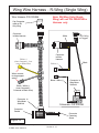
Wing Wire Harness - RH Wing Only........................................... 4-12
Wing Wire Harness - Dual Wing................................................. 4-13
Pump & Motor Hyd Schematic - RH Wing Only............................ 4-14
Pump & Motor Hyd Schematic - Dual Wing................................. 4-15
Pump & Motor Hyd Schematic................................................... 4-16 to 4-18
Interstater (Service Manual) 03/06
© 2006 Alamo Industrial
Index 1 -2
INDEX
Section
Page
Index.......................................................................................................................... Index-2 of Index 3
Section 5
Hydraulic Pumps
Tandem - Single - Auxiliary - Remove - Repair - Replace....................................... 5-1 to 5-37
Tandem & Single Pump - Removal.............................................. 5-2 to 5-3
Tandem & Single Pump - Repair / Replace.................................. 5-4 to 5-5
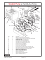
Tandem Pump - W/ Tank & Aux Pump........................................ 5-6
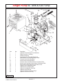
Single Pump - W/ Tank & Aux Pump...........................................5-7
Tandem Pump & Driveshaft Asy - W/ Aux Pump.......................... 5-8
Tandem Pump & Driveshaft Asy - W/O Aux Pump........................ 5-9
Single Pump & Driveshaft Asy - W/ Aux Pump............................. 5-10
Single Pump & Driveshaft Asy - W/O Aux Pump.......................... 5-11
Tandem & Single Pump - Remove / Replace................................ 5-12 to 5-13
Tandem Pump - Disassembly & Reassembly............................... 5-14 to 5-22
Single Pump - Disassembly & Reassembly................................. 5-23 to 5-26
Auxiliary Pump - Remove & Repair.............................................. 5-27
Auxiliary Pump - Remove & Replace........................................... 5-28
Auxiliary Pump - Disassembly.................................................... 5-29
Auxiliary Pump - Reassembly..................................................... 5-30
Auxiliary Pump - Reassembly & Reinstall.................................... 5-31
Auxiliary Pump - Removal, Repair & Replace............................... 5-32 to 5-33
Hyd Schematic W/ Aux Pump - RH Wing.................................... 5-34
Hyd Schematic W/ Aux Pump - Dual Wing.................................. 5-35
Hyd Schematic W/O Aux Pump - RH Wing................................. 5-36
Hyd Schematic W/O Aux Pump - Dual Wing............................... 5-37
Section 6
Hyd Tank & Return Filter - Remove & Replace............................................. 6-1 to 6-6
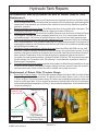
Hyd Tank Repairs...................................................................6-2 to 6-4
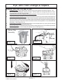
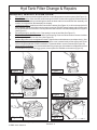
Hyd Tank Filter Change & Repairs........................................ 6-5 to 6-6
Section 7
Pump Mount Weldment & Driveshaft - Remove & Replace......................... 7-1 to 7-4
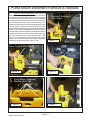
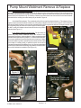
Pump Mount Weldment Remove & Replace Remove.................... 7-2 to 7-4
Section 8
Cable - Control Valve Connections................................................................ 8-1 to 8-20
Joystick, Valve & Control Cables (Cab)....................................... 8-8
Valve to Cylinder Hose Connections (Cab & Rops)....................... 8-9
Valve Connections (Rops Tractor)............................................... 8-10 to 8-12
Wire Harness Connections (Cab & Rops).................................... 8-13 to 8-15
Motor Control Switch - Dual Wing............................................... 8-16
Motor Control Switch - RH Wing Only......................................... 8-17
Wing Wire Harness - RH Wing Only........................................... 8-18
Wing Wire Harness - LH Wing (Dual Wing).................................. 8-19
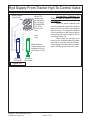
Hyd Supply From Tractor Hyd To Control Valve............................ 8-20
Interstater (Service Manual) 03/06
© 2006 Alamo Industrial
Index 1 -3
INDEX
Section
Page
Index.............................................................................................................. Index-3 of Index 3
Section 9
Main Frame & Wing Lift Arm Weldment........................................................ 9-1 to 9-5
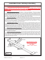
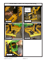
Install Main Frame / RH Only & Dual Wing.................................. 9-2 TO 9-5
Section 10
Hydraulic Motors for Wing Mowers
Remove - Repair - Replace........................................................................... 10-11
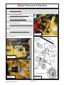
Motor - Removal & Replace........................................................ 10-2 TO 10-5
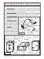
Motor Manifold - Remove, Repair & Replace................................. 10-6 to 10-7
Motor - Disassembly & Reassembly........................................... 10-8 to 10-11
Section 11
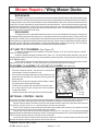
Wing Mower - Remove - Repair - Replace.................................................... 11-1 to 11-25
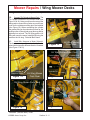
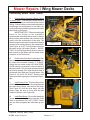
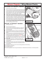
Mower Repairs / Wing Mower Decks........................................... 11-2 TO 11-7
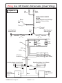
Wing Cut Off Switch Schematic - Dual Wing................................ 11-8
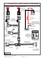
Wing Motor Control Switch - Dual Wing....................................... 11-9
Motor Control Switch - RH Wing Only.......................................... 11-10
Pump & Motor Hyd Schematic - RH Wing Only............................ 11-11
Pump & Motor Hyd Schematic - Dual Wing................................. 11-12
Pump & Motor Hyd Schematic - RH Wing................................... 11-13
Pump & Motor Hyd Schematic - Dual Wing................................. 11-14
Pump & Motor Hyd Schematic................................................... 11-15 to 11-17
Mower Repairs / Wing Mower Decks........................................... 11-18 TO 11-25
Section 12
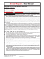
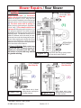
Rear Mower Repairs...................................................................................... 12-1 to 12-20
Mower Repairs / Rear Mower...................................................... 12-2 TO 12-11
G/B & Ext'n Shaft Asy / Rear Mower........................................... 12-13
Gearbox Asy - P/N 700493.........................................................12-14
Gearbox P/N 700493 - Asy Instructions....................................... 12-15
Gearbox Asy - P/N 702673.........................................................12-16
Gearbox P/N 702673 - Asy Instructions....................................... 12-17
Lubrication Points......................................................................12-18
Initial Start-Up Procedure............................................................12-19 to 12-20
Section 13
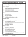
Delivery Inspection Sheet................................................................................... 13-1 to 13-4
Interstater Delivery Inspection Checklist....................................... 13-2 TO 13-4
Interstater (Service Manual) 03/06
© 2006 Alamo Industrial
Index 1 -4
Section 1
Interstater
SERVICE MANUAL
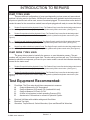
Introduction To Repairs
This section is the Introduction to
making repairs on Interstater model.
Recommended procedures & tools
recommended .
Interstater - Service Manual (03/06)
© 2006 Alamo Industrial
Section 1 - 1
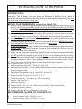
INTRODUCTION TO REPAIRS
GENERALREPAIR / REPLACEMENT INFORMATION:
A. To disassemble / repair your INTERSTATER this manual is designed to assist you with drawings, instructions
B.
C.
D.
E.
F.
G.
H.
I.
and information. This manual is designed to be used in conjunction with the parts manual, operators manual
and the assembly manuals. If additional information or clarification is needed contact your Alamo Industrial
factory representative.
Some of these instructions are general information and not specifically for your tractor, but in connection with
our drawings, they may not show the exact application and tractor you have. In many cases to assembly
manual for your mower to tractor application will clarify some clarity to exact applications.
This section covers the removal, repair and reinstallation of the hydraulic pump procedure for the Alamo
Industrial Interstater mower, it also includes instruction for driveshaft, hoses, and miscellaneous parts to be
attached the hydraulic pumps to the tractor.
These instructions are for working on the pumps used to power wing mower/mowers, right side mower, and
left side mower units if dual wing model. For mounting one mower side only, disregard information concerning
the opposite side. Hardware quantities shown are for both sides.
The Auxiliary pump is used to supply the lift and tilt hydraulic cylinder circuit. This auxiliary pump will not
be used on all units, some will use the tractor hydraulic system to supply cylinder circuit.
Reference to the left or right side of the Interstater is determined while facing the front of the tractor from the
drivers seat.
The part quantities shown for an illustration pertain only to that phase of repair. The quantity given corresponds
to the number of parts needed. When repairing a single-sided model based on a dual-sided model, the quantity
furnished will usually be half the quantity listed.
Large parts may not always be listed next to an illustration because they are usually easy to identify them
from name or description.
This manual makes reference to individual component parts, some of which may have been pre-assembled
at the factory.
Abbreviation of Parts Terminology :
Whenever reference is made to parts, listed for an illustration or elsewhere in this manual, the following
abbreviations may be used:
1.
ASY - Assembly
2. ASSY - Assembly
3. AUX - Auxiliary
4.
BRG - Bearing
5. BRKT - Bracket
6
CYL - Cylinder
7.
CW - Clockwise
8. CCW - Counter Clockwise
7. EXT - Extreme
8.
EXT’N - Extend / Extension
9. F/ - For or From
10. FM - Female Boss
11.
FP - Female Pipe
12. FSTNR - Fastener
13. FT - Foot / Feet
14.
GB - G/B - Gearbox
15. GR - Grade
16. HD - Heavy Duty
17.
HHCS - Hex Head Capscrew
18. HRDND - Hardened
19. HYD - Hydraulic
20.
IN - Inch
21. LB - Pound
22. LH - Left Hand
23.
LW - Lock Washer
24. M - Metric
25. MB - Male Boss
26.
MM - Millimeters
27. MNT - Mount
28. MP - Male Pipe
29.
MTR - Motor
30. N/A - Not Applicable
31. NC - National Coarse
32.
NF - National Fine
33. NLA - No Longer Available
34. NLF - No Longer Furnished
35.
NPT - National Pipe Thread
36. P1.5 - Thread Pitch
37. P2.0 - Thread Pitch
38.
P2.5 - Thread Pitch
39. PL - Plated
40. PLT - Plate
41.
PMP - Pump
42. PTO - Power Take Off
43. PW- Plain Washer
44.
REV - Reverse
45. RH - Right Hand
46. ROT - Rotation
47.
RPM - Revolutions Per Minute
48. SCKT - Socket
49. SD - Severe Duty
50.
SRV - Service
51. STD - Standard
52. SVR - Severe
53.
W/ - With
54. W/O - With Out
55. WLDMNT - Weldment
When installing fasteners, PW and LW (generally installed in that order) are usually on the side of the
fixture or part being fastened that the hex/lock nut is on. When only HHCS, LW and/or PW are required, they
are generally installed in that order. Some parts do not require a PW or LW. Refer to illustrations for exceptions.
Fasteners should be installed so they cause the least interference with other parts. When securing driveshaft
pulley to hub, tighten fasteners to 9 lb-ft torque.
Interstater - Service Manual (03/06)
© 2006 Alamo Industrial
Section 1 - 2
INTRODUCTION TO REPAIRS
INTRODUCTION:
In Most diagrams there are no Component Part Numbers Listed, Only Item numbers and
Descriptions, This is because most parts shown as breakdown in drawings are for location &
identification only and if available as replacement parts will be listed in the Parts/Operators Manual. NO
Dirt at all should be around Parts during repairs.
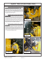
BEFORE STARTING REPAIRS: Service Rules (READ THIS)
1.
2.
3.
4.
5.
6.
7.
8.
9.
Remove Front Cover. Clean Pump and surrounding area completely before removing any connec
tions or Lines. NO DIRT OR DEBRIS CAN BE ALLOWED ON OR NEAR HYDRAULIC SYSTEM IF
IT IS BEING WORKED ON, ANY DIRT OR CONTAMINANTS IN SYSTEM NO MATTER HOW
SMALL WILL DAMAGE SYSTEM!
After cleaning around all connections thoroughly, Disconnect all connections, Lines, Hoses, Wiring
and Remove the Pump Completely from the Tractor. Plug all hoses and Lines on Tractor and on
Pump, DO NOT leave any open Lines. NO Contamination Should be allowed into system at all.
Clean Area, Clean all Tools, Pans etc. The cleaning of Area and Tools MUST be done before moving
(Cleaned) Pump there. Drain Oil from Pump, Recheck outside of Pump to Make Sure it is Clean
After disassembly of Pump wash all metal components in clean solvent.
Use compressed Air to dry parts after washing (Compressed air must be filtered and moisture free).
DO NOT wipe them dry with Paper Towels or Cloth as these will leave lint and/or dust contamination.
DO NOT USE Compressed Air to spin any component (Such as Bearings or Plates) as this will
damage them and could be dangerous.
Always use new Seals when reassembling Hydraulic Pumps, Lubricate the new rubber Seals with
a Petroleum Jelly, (Vaseline) before installing them.
DO NOT reinstall worn/damaged Parts in Pump, DO NOT Use a worn/damaged Pump Housing.
Torque all Bolts over Gasketed Joints. Then repeat the Torque sequence to make sure Bolts are tight,
some times Gaskets can give a Torque reading that is OK but is not, so always recheck Torque.
Verifying the accuracy of Pump Repairs on an authorized test stand is essential.
RECOMMENDED TOOLS:
1.
2.
Hex Allen Wrench (Qty 5) (9/16", 5/32", 5/16", 3/32", 5/64"
Retaining Ring Pliers (Qty 3), 1 each of Internal (Straight .070 tip) internal (Straight .090 tip) & 1 each
External (Straight 0.90 tip)
3. Retaining E-Ring Applicator (Qty 2), 1 each 9/32" & 1 each 1/2".
4. O-Ring Pick (Qty 1)
5. End Wrench (Qty 4), 1 each of 7/16", 9/16", 3/4", 1"
6. Torque Wrench (Qty 1), 0 to 100 ft. lbs. (135.6 nm) capacity
7. Hammer, Soft Face (Qty 1)
8. Seal Driver Set (Qty 1)
9. Arbor Press (Qty 1)
10. Sockets (Qty 3) 7/16", 9/16", 3/4" , Drive Size should match Torque Wrench Drive)
11. Light Petroleum Jelly (Vaseline)
12. Locktite, # 222 and #277 or equivalent (Qty 1 tube each)
RECOMMENDED GAUGES FOR DIAGNOSTICS:
1.
2.
3.
Inlet Vacuum: 30 PSI to 30 in Mercury (207 bar to 0 bar)
System Pressure Gauge: 6,000 PSI (700 bar)
Charge Pressure Gauge: 0 to 500 PSI (0 to 25 bar)
Interstater - Service Manual (03/06)
© 2006 Alamo Industrial
Section 1 - 3
INTRODUCTION TO REPAIRS
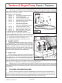
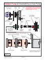
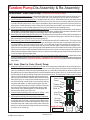
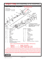
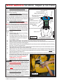
PUMP TYPES USED:
There are different configurations of pump used depending on how mower unit was ordered
and how it is being used on the tractor. All Below will used the same hydraulic tank which means not
all ports on hydraulic tank will be used, some will remained plugged. The connections on the tank will
remain the same for the connections needed, leave all ports plugged until ready to connect the fittings.
1.
Tandem Pump with Auxiliary Hydraulic Pump, The Tandem Pump is used for the dual wing model mower
and the auxiliary pump is used to supply the hydraulic cylinders and cylinder control valve. (See Figure 1)
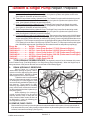
2.
Tandem Pump without Auxiliary Hydraulic Pump, The Tandem Pump is used for the dual wing model
mower and the tractors hydraulics are used to supply the hydraulic cylinders and cylinder control valve. (See
Figure 2)
3.
Single Pump with Auxiliary Hydraulic Pump, The Single Pump is used for the Single wing model mower
and the auxiliary pump is used to supply the hydraulic cylinders and cylinder control valve. (See Figure 3)
4.
Single Pump without Auxiliary Hydraulic Pump, The Single Pump is used for the dual wing model mower
and the tractors hydraulics are used to supply the hydraulic cylinders and cylinder control valve. (See Figure 4)
PUMP DRIVE TYPES USED:
The pump drives system is basically the same on on most interstater mowers. The part
numbers will vary some from tractor types used. The size and/or part sizes will vary. The best way to
determine which drive component you have for your tractor model is consult the interstater assembly
manual for the tractor used.
1.
Tandem Pump with Auxiliary Hydraulic Pump, The Tandem Pump is used for the dual wing model mower
and the auxiliary pump is used to supply the hydraulic cylinders and cylinder control valve. (See Figure 1)
2.
Tandem Pump without Auxiliary Hydraulic Pump, The Tandem Pump is used for the dual wing model
mower and the tractors hydraulics are used to supply the hydraulic cylinders and cylinder control valve. (See
Figure 2)
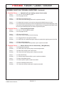
Test Equpment Recommented:
1.
Flow Meter, The Flow meter should have components to measure:
A.
Guage to Measure the Oil Temperature.
B.
Gauge to Measure Oil Pressure PSI (Load and No Load).
C.
Gauge to Measure Oil Flow in G.P.M.
D.
A Valve to load system to check operating Pressure (PSI).
E.
Assortment of Connections to connect to Hydraulic System.
2.
3.
4.
Electrical Volt Meter with variable settings and Ohm Meter.
Electrical Test Light.
Wrenches, Torque Wrench, Socket Wrenches, Open and Boxed End Wrenches.
Interstater - Service Manual (03/06)
© 2006 Alamo Industrial
Section 1 - 4
Section 2
Interstater
SERVICE MANUAL
Trouble Shooting Information
This section list possible failures,
causes and solutions. All possible
failures cannot be listed, only some
of the most common problems.
Interstater - Service Manual (03/06)
© 2006 Alamo Industrial
Section 2 - 1
Possible Failure / Cause / Solution
MOWER FUNCTION TROUBLE SHOOTING:
1 - Possible Failure........... Mower will note rotate
Cause........... 1-A. Inline fuse on Wire harness failed.
Solution........ 1-A. Replace fuse as required.
Cause........... 1-B. Magnetic Safety Switch not making contact.
Solution........ 1-B. Adjust or replace switch as required.
Cause........... 1-C. Broken or worn drive belts.
Solution........ 1-C. Replace drive belts as needed.
Cause........... 1-D. ON / OFF Switch defective or broken
Solution........ 1-D. Inspect, test switch and replace as required.
Cause........... 1-E. Insufficient Voltage through solenoid.
Solution........ 1-E. Check solenoid coil and wiring, replace/ repair as needed.
Cause........... 1-F. Solenoid Spool will not shift completely
Solution........ 1-F. Clean or replace solenoid cartridge
2 - Possible Failure........... Mower will not stop
Cause........... 2-A. Solenoid Spool will not shift
Solution........ 2-A. Clean or replace solenoid cartridge
3 - Possible Failure........... Intermittent mowing power
Cause........... 3-A. Safety switch maladjustment
Solution........ 3-A. Adjust safety switch
Cause........... 3-B. Electrical Malfunction
Solution........ 3-B. Check electric circuit, magnetic switches and push pull switch.
Cause........... 3-C. Bad Solenoid
Solution........ 3-C. Check solenoid, replace as needed.
4 - Possible Failure........... Insufficient cutting power or low cutter shaft speed.
Cause........... 4-A. Drive belts slipping.
Solution........ 4-A. Check for correct belts, condition of belts, check idler pulley and spring tension system
for idler pulley, replace and / or repair as needed.
Cause........... 4-B. Bound cutter shaft.
Solution........ 4-B. Free up cutter shaft.
Cause........... 4-C. Hydraulic Pressure relief stuck open or setting to low.
Solution........ 4-C. Check setting and condition of hydraulic relief valve. Repair / replace as needed.
Cause........... 4-D. Solenoid Spool will not shift completely.
Solution........ 4-D. Replace solenoid valve cartridge.
Cause........... 4-E. Worn Pump or Motor
Solution........ 4-E. Check pump and motor, repair or replace as needed.
Interstater - Service Manual (03/06)
© 2006 Alamo Industrial
Section 2 - 2
Possible Failure / Cause / Solution
MOWER FUNCTION TROUBLE SHOOTING:
(Continued)
5 - Possible Failure........... Hydraulic oil over heating, mower free to rotate
Cause........... 5-A. Low oil level in hydraulic system.
Solution........ 5-A. fill to proper oil level.
Cause........... 5-B. Relief valve setting too high.
Solution........ 5-B. Check relief valve setting, repair and /or replace as needed.
Cause........... 5-C. Obstruction in power circuit, extra or wrong parts installed in pump or motor
Solution........ 5-C. Find and remove obstruction. Check if components have been reassembled lately, if they
have check for being assembled wrong, re- installed wrong or wrong parts used. Make certain
the correct and standard parts were used as replacement parts.
6 - Possible Failure........... Pump making load noise
Cause........... 6-A. Low oil level in hydraulic system.
Solution........ 6-A. fill to proper oil level.
Cause........... 6-B. Vacuum in Reservoir
Solution........ 6-B. Check, Clean or replace reservoir vent plug.
Cause........... 6-C. Clogged oil filter or wrong filter installed.
Solution........ 6-C. Check filter for condition and type, replace as needed with original type and size filter.
Cause........... 6-D. Worn or damaged pump
Solution........ 6-D. Check Pump condition and operation, repair / replace as needed.
7 - Possible Failure........... Mower will not raise or raises slowly (Wing Mowers)
Cause........... 7-A. Slow gear pump speed
Solution........ 7-A. Check gear pump speed, pulleys, belts and adjustments.
Cause........... 7-B. Relief valve setting to low or stuck open.
Solution........ 7-B. Check relief valve setting, repair or replace as needed.
Cause........... 7-C. Worn Gear Pump.
Solution........ 7-C. Check pump pressure and flow, repair or replace as needed.
Cause........... 7-D. Worn or damaged cylinder.
Solution........ 7-D. Check cylinder, repair or replace as needed.
Cause........... 7-E. Worn or damaged control valve.
Solution........ 7-E. Check valve sections and repair or replace as needed.
Interstater - Service Manual (03/06)
© 2006 Alamo Industrial
Section 2 - 3
Possible Failure / Cause / Solution
MOTOR CIRCUIT TROUBLE SHOOTING:
1 - Possible Failure........... Motor turns but in wrong direction
Cause........... Motor manifold block is installed wrong on motor
Solution........ Motor manifold block must be refitted to motor to achieve correct rotation, See motor
change rotation page 7-22 in mower repair section.
2 - Possible Failure........... Motor fails to engage when electric switch activated.
Cause........... Electrical connection failure Switch, solenoid or wire harness
Solution........ Test Switch for current and activation, test solenoid coil for current and activation.
Cause........... Pump driveshaft malfunction.
Solution......... Inspect pump driveshaft for damage to splines or drive components. Make certain pump
is turning, if not inspect splined coupler at pump and drive shaft. Repair as required.
Cause........... Lack of sufficient hydraulic pressure and volume.
Solution......... Perform a pressure and flow test on hydraulic system
3 - Possible Failure........... Motor turns but cutter shaft will not.
Cause........... Broken drive belts, pulley keys or pulley retaining hardware
Solution........ Inspect belts, keys, pulley and mounting hardware, replace / repair as required.
4 - Possible Failure........... Motor turns if unloaded, slows down or stops as load is applied.
Cause............ A. Scored back plate.
Solution......... A. Remove back plate and examine surface condition of flat area; if scored, replace
back plate. DO NOT LAP back plate.
Cause............ B. Scored or worn piston shoes.
Solution......... B. Disassemble motor, examine condition of shoes on pistons; replace pistons as a
complete set if necessary. DO NOT LAP.
Cause............ C. Low relief valve pressure.
Solution......... C. Check relief valve for proper pressure setting; adjust or replace relief valve.
5 - Possible Failure........... Motor will not turn
Cause............ A. Severely scored back plate.
Solution......... A. Disassemble motor completely. Inspect all parts, clean all parts, replace all worn parts
and flush hydraulic system.
6 - Possible Failure........... Motor free wheels
Cause............ A. Oil-flow and pressure shut off going to motor.
Solution......... A. When the hydraulic system is shut off, either by shutting off the engine on a closed
loop system or returning the control valve spool to neutral on an open center system, the
motor will free wheel after it has leaked off. This is inherent in the design. On a closed
loop or propulsion system, the motor will not free wheel as long as charge pressure is
maintained to and from the motor.
7 - Possible Failure........... Excessive case drain flow.
Cause........... A. Excessive internal wear in motor.
Solution........ A. Disassemble motor, inspect parts and replace as necessary. Case drain flow should
not exceed 1.5 GPM at full pressure.
Interstater - Service Manual (03/06)
© 2006 Alamo Industrial
Section 2 - 4
Possible Failure / Cause / Solution
MOTOR CIRCUIT TROUBLE SHOOTING:
(Continued)
8 - Possible Failure........... System will not operate in either direction.
Cause........... A. Oil supply low.
Solution........ A. Check oil level and fill as needed
Cause........... B. Oil filter clogged
Solution........ B. Replace filter element
Cause........... C. Oil too heavy
Solution........ C. Use proper viscosity oil
Cause........... D. Drive coupling broken
Solution........ D. Inspect coupling for sheared spline or key.
9 - Possible Failure........... System noisy.
Cause........... A. Air in system due to low oil level
Solution........ A. Fill in reservoir to sight glass
Cause........... B. Loose suction line
Solution........ B. Tighten fittings
Cause........... C. Clogged suction filter
Solution........ C. Replace filter element
Cause........... D. Internal pump or motor damage
Solution........ D. Disassemble, inspect, and repair
10 - Possible Failure......... Sluggish response to acceleration or deceleration.
Cause........... A. Air in system
Solution........ A. Check oil level and fill. Check for loose suction line and or fittings. Check for clogged
suction filter and replace as needed. Oil to heavy, change to proper viscosity oil.
Cause........... B. Internal pump or motor wear or damage
Solution........ B. Disassemble, inspect, and repair
Interstater - Service Manual (03/06)
© 2006 Alamo Industrial
Section 2 - 5
NOTES
Interstater - Service Manual (03/06)
© 2006 Alamo Industrial
Section 2 - 6
Section 3
Interstater
General
Specifications
Interstater - Service Manual (03/06)
© 2006 Alamo Industrial
Section 3 - 1
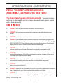
SPECIFICATIONS - INTERSTATER
READ THIS BEFORE BEGINNING
ASSEMBLY, REPAIRS OR TESTING:
The Interstater has electric components:. The electric components can be damaged if care is not taken when performing repairs, testing
and/or during assembly.
DO NOT
1.
DO NOT short any wires across or allow them to be shorted out.
2.
DO NOT attempt to jump across any wires or supply them with alternate power
source.
3.
DO NOT install higher rated fuses than are recommended by manufacturer.
4.
DO NOT do any welding on unit unless the computer modules are unplugged first (If
equipped with electronics), this is to prevent a power surge going into modules (THIS IS
VERY IMPORTANT). This could also apply to the tractor components. Check Tractors
repair guide for specific instruction about tractor model and type.
5.
DO NOT attempt to repair or adjust a component that is not intended to be repaired,
example sealed components as there are no serviceable components inside.
6.
DO NOT let anyone attempt any testing or repairs unless they are an experienced
and qualified technician. Technicians must have proper tools, gauges, meters etc. to
perform proper diagnosis and/or repairs.
7.
DO NOT perform any repairs with dirty tools or in dirty area. When working on hydraulic
components, keeping system clean and free of contamination is important.
8.
DO NOT start or engage system if the oil level is not at the proper level or condition. Never
start or run unit low or out of oil.
9.
DO NOT install / add any oil unless you know it is the correct type and the container is
clean. Make certain the oil is not contaminated with dirt or any liquid.
10.
DO NOT Operate any mowers that have a vibration when running, cause of vibration must
be fond and repaired before running. Vibrating Flail Mower running will damage them!
Interstater - Service Manual (03/06)
© 2006 Alamo Industrial
Section 3 - 2
SPECIFICATIONS - INTERSTATER
Standard Equipment and Specifications
1.
BASE UNIT SPECIFICATIONS:
Overal Cutting Width..........................................16’5”,18’5”, or 20’9” Overal Cutting Widths
Frame Construction........................................... Full-Length Welded Tubular Frame With Transport Lock
Reservoir Capacity.............................................19-Gallon Reservoir with 12 Micron Filtration
Pump Type & Rating. (Dual Wing Interstater).......Tandem Piston Pumps Rated @ 48 GPM @ 3800 PSI
(Single Wing Interstater).... Tandem Piston Pump Rated @ 24 GPM @ 3800 PSI
Cylinder Control Valve (Dual Wing Interstater).......4-Spool Valve with Detent Position
(Single Wing Interstater).... 2-Spool Valve with Detent Position
2.
WING MOWER SPECIFICATIONS:
Wing Mower cutting Width Options..................... 62”. 74”, or 88” Cutting Widths
Cutter Housing Construction...............................10 Guage Unitized Cutter Housing
Deck End Plates............................................... 1/2” Inboard & 5/16” Outboard Thick Side Plates
Skid Shoe Type.................................................Bolt On Replaceable Skid Shoes
Cuttershaft Size................................................ 4-1/2” x 5/16” Wall Cuttershaft
Bearing Size & Type.......................................... 1-5/16” Bore Greasable, Self-Aligning Cuttershaft Bearings
Motor Tpe & Size.............................................. 53 HP Piston Motor
Cuttershaft Drive................................................Belt Drive F/Motor to Cuttershaft w/ Automatic Spring Tension
Cutter Shaft Drive Belt....................................... V-Belt w/ Kevlar Construction
Rear Roller Type................................................Steel Tube Construction w/ Bell Ends & Hex Shaft
Rear Roller Bearings......................................... Greasable, Sealed w/ Housing and Hex ID
Rear Roller Adjustment...................................... 6” Adjustable Rear Roller
Cutting Height Adjustment................................. 1/2” Down to 6” Up Cutting Height (Rear Roller)
Knife Options.................................................... Available in Fine or Coarse-Cut
Safety Deflectors.............................................. Front and Rear Safety Deflectors Standard
Wing Motor Cut-Switch...................................... Automatic Cut-Off Switch When Wings Raised
Lift Cylinder Capacity......................................... Lift Cylinder Capable of 14” Vertical Lift
Tilt Cylinder Capacity......................................... Tilt Cylinder Capable of 45 Degrees Down & 90 Degrees Up
3.
REAR MOWER SPECIFICATIONS:
Rear Mower cutting Width Options......................88” or 96” Cutting Width (Depending on tctr mnt. kit)
Cutter Housing Construction...............................10-Guage Unitized Cutter Housing
Deck End Plates............................................... 5/16” Thick Side Plates Both Ends
Skid Shoe Type.................................................Bolt On Replaceable Skid Shoes
Cuttershaft Size................................................ 4-1/2” x 5/16” Wall Cuttershaft
Cuttershaft Drive................................................Belt Drive f/Gearbox to Cuttershaft w/ Automatic Spring Tension
Cutter Shaft Drive Belt....................................... V-Belt w/ Kevlar Construction
Bearing Size & Type.......................................... 1-5/16” Bore Greasable, Self-Aligning Cuttershaft Bearings
Cuttershaft Drive................................................60 HP Gearbox, Shielded Driveline Driven
Gearbox Drive................................................... Cat IV Shielded Driveline, PTO Driven
Gearbox Driveline Connection............................. Adjustable Torque Limiter Clutch
Rear Roller Type................................................Steel Tube Construction w/ Bell Ends & Hex Shaft
Rear Roller Bearings......................................... Greasable, Sealed w/ Housing and Hex ID
Rear Roller Adjustment...................................... 6” Adjustable Rear Roller
Cutting Height Adjustment................................. 1/2” Down to 6” Up Cutting Height (Rear Roller)
Knife Options.................................................... Available in Fine or Coarse-Cut
Safety Deflectors.............................................. Front and Rear Safety Deflectors Standard
Rear Mower Cut-Off........................................... Tractor PTO Controls, Controled By Tractor Operator
Reat Mower to Tractor Connection...................... CAT I or CAT II Three Point Hitch
Interstater - Service Manual (03/06)
© 2006 Alamo Industrial
Section 3 - 3
SPECIFICATIONS - INTERSTATER
4.
TRACTOR REQUIREMENTS:
The tractor used to operate the mower must have the power, capacity and required equipment to safely
operate the mower at a ground speed between 2 and 5 MPH. Operating the mower with a tractor that does not
meet the following requirements may cause tractor or mower damage and could be a potential danger to the
operator and passersby.
Tractor Requirements and Capabilities
¾ASAE approved Roll-Over Protective Structure ........... .. (ROPS) or ROPS cab and seat belt.
¾Tractor Safety Devices...........................……............... Slow Moving Vehicle (SMV) emblem, lighting, PTO
master shield
¾Tractor Horsepower -Minimum .....................................Rear INT 88” 60hp, Rear INT 96” 60 hp
¾Drawbar..................................................................... 14” length-measured from end of PTO shaft to hitch
pin hole, rated to carry mower tongue weight, safety
chain attachment point
¾Hydraulics..................................................................4-Spool Valve & 2-Spool Valve with Detent Position
¾Front End Weights..…………...................................... As needed to maintain 20% weight on tractor front
axle
¾Power Take Off........................................................... 540 RPM
5.
ROPS and Seatbelt:
A Roll-Over-Protective-Structure (ROPS) and seat belt are essential to protect the operator from falling off
the tractor, especially during a roll over where the driver could be crushed and killed. The ROPS and seat belt must
be used in conjunction with one another. Only operate the tractor with the ROPS in the raised position and seat
belt fastened. Tractor models not equipped with a ROPS and seat belt should have these life saving features
installed by an authorized dealer.
WARNING!
Operate this Equipment only with a Tractor equipped with an approved roll-overprotective system (ROPS). Always wear seat belts. Serious injury or even death
could result from falling off the Tractor--particularly during a turnover when the
operator could be pinned under the ROPS. (SG-7)
6.
TRACTOR SAFETY DEVICES:
If transporting or operating the tractor and mower near a public roadway, the tractor must be equipped with
proper warning lighting and a Slow Moving Vehicle (SMV) emblem which are clearly visible from the rear of the unit.
Lights and a SMV emblem must be equipped directly on implements if the visibility of the tractor warning signals are
obscured.
Maintain all manufacturer equipped safety shields and guards. Always replace shields and guards that were
removed for access to connect, service, or repair the tractor or mower. Never operate the tractor PTO with the PTO
master shield missing or in the raised position.
7.
TRACTOR HORSEPOWER REQUIREMENTS:
The horsepower required to operate the mower depends on many factors including the vegetation to be cut, terrain
condition, operator experience, and condition of the mower and tractor. For most mowing condition, the Rear INT 88”
& 96”mowers require a tractor with at least 60HP. Operating the mower with a tractor that does not have adequate
power may damage the tractor engine.
8.
TRACTOR 3-POINT HITCH REQUIREMENTS:
The tractor 3-point hitch must be rated to lift at least 1035 lbs. if attaching a INT 88”, and 1170lbs. if attaching
a INT 96” flail.
Interstater mowers can attach to tractor’s with either a CAT I or II hitch. Refer to the tractor operator’s manual
for the category of the tractor used. If the hitch does not conform to ASAE Cat I or II dimensions, the mower may not
(Continued Next Page)
Interstater - Service Manual (03/06)
© 2006 Alamo Industrial
Section 3 - 4
SPECIFICATIONS - INTERSTATER
(Continued From previous Page)
fit or raise properly. Consult an authorized dealer for possible
modification procedures to mount nonconforming hitches.
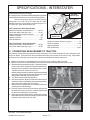
Use the correct hitch pins for the hitch category
being used. For a Cat I hitch, 7/8” lower and 3/4” upper
diameter hitch pins are used and Cat II hitches require 1-1/
8” lower and 1” upper diameter hitch pins.
Top Link
Attaches Here
CAT I Implement / Hitch Specification
Width from outside to outside A-frame ........... 26-7/8”
Quick Hitch width inside lug to lug ................ 27-1/8”
Height from bottom hitch pin to top pin ................ 18”
Lower pin diameter ............................................. 7/8”
Upper pin diameter ............................................. 3/4”
Linch pin diameter .......................................... 15/32”
CAT II Implement / Hitch Specification
Width from outside to outside A-frame ........... 32-3/8”
Quick Hitch width inside lug to lug ................ 33-5/8”
Lift Arms
Attach Here
Height from bottom hitch pin to top pin ................ 19”
Lower pin diameter .......................................... 1-1/8”
Upper pin diameter ................................................ 1”
Linch pin diameter .......................................... 15/32”
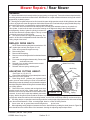
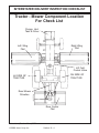
9. CONNECTING REAR MOWER TO TRACTOR:
Use extreme caution when connecting the mower to the tractor. The mower should be securely resting at ground
level or on blocks. Place a block in front of and behind the tires to prevent the mower from moving. Keep hands
and feet out from under the mower and clear of pinch points between the tractor and mower.
A. Make sure the tractor is equipped with the correct PTO shaft. Change shafts if needed.
B. Shorten or remove the tractor drawbar to avoid interference when raising and lowering the mower.
C. Board the tractor and start the engine. Position the tractor
to the mower with the 3-point lift arms positioned between
the respective set of mower A-frame lift lugs. Note: Set the
3-point lift control to “Position Control” so
that the lift arms maintain a constant height when attaching
the mower. See the tractor Operator’s Manual for correct
settings when attaching 3-point equipment.
D. Turn off the tractor engine and dismount.
E. One lift arm at a time, align arm end hole between the set
of A-frame lift lugs. Insert hitch pin through the lug and arm
holes and insert retaining pin into hitch pin.
F. Walk around to opposite side and repeat procedure for
remaining lift arm and hitch pin.
G. Extend or retract 3-point top link to align its end hole with
the holes of the mower’s top link. Insert the top link hitch
pin and insert retaining pin into hitch pin.
H. Adjust any lower link check chains, guide blocks, or sway
blocks to prevent the mower from swaying side to side and
possible contact with tractor rear tires.
Interstater - Service Manual (03/06)
© 2006 Alamo Industrial
Section 3 - 5
SPECIFICATIONS - INTERSTATER
10.
LEVELING REAR MOWER:
To Facilitate a safe and efficient mowing
operation, the mower should be operated parrallel to
the ground at all times. Never operate if front or rear of
mower is tilted upward. Objects may be discharged at
high speeds causing possible injury or even death.
Adjust Top Link to level mower roller
adjustment. Side Skid Shoes should always be parallel
to ground throughout the full adjustment range. Adjust
cutting height of machine by raising or lowering rear
roller as specified in Operation Section.
11.
TOP LINK
TRACTOR HYDRAULICS:
The wing mowers are raised and lowered with 2 hydraulic cylinders,a till and lift cylinders, for each wing
section. Hydraulic lines are plumbed together and controlled by a 4-spool or 2 spool control valve. The tractor
must be equipped with either a 4-spool valve or 2-spool valve,open center system, with main pressure relief and
detent position. During operation, the tractor hydraulics must be set in the float detent to enable the mower
sections to follow the contour of the terrain. The oil returning from the cutter unit motor flows through the oil
cooler tubes. Under normal mowing conditions, the knives blow air against the cooling tubes to maintain oil
temperature approximately 60 deg. above ambient temperature. Should the cutter unit become overloaded,
the oil temperature will rise very quickly. Under no circumstances should the unit be operated if the oil
temperature is above 180 deg.F. If the oil reaches this temperature, raise the mower and let the tractor run
without the cutter load.
12.
FRONT END WEIGHT:
Maintain a minimum of 20% total tractor weight on the tractor front end at all times. Front end weight is
critical to maintain steering ability and to prevent the front end from rearing up. Consult your authorized tractor
dealer for front weights and carriers.
13.
TRACTOR POWER TAKE OFF (PTO):
Only operate the mower on a tractor equipped to operate at 540 rpm PTO speed. Tractors operating at
540 rpm will have a 1-3/8” diameter 6-spline PTO shaft stub. Refer to the tractor operator’s manual for operating
the PTO at the proper speed.
If operating an older model tractor where the tractor’s transmission and PTO utilize one master clutch, an
over-running clutch must be used between the PTO output shaft and the driveline of the mower. Consult an
authorized tractor dealer to purchase and install an over-running clutch if needed.
14. SETTING MOWER CUTTING HEIGHT:
Properly setting the cutting height is essential for efficient and safe operation. A properly set mower
makes a more uniform cut, distributes clippings more evenly, increases tractor efficiency, and follows the contour
of uneven terrain. Note: Avoid very low cutting heights, striking the ground with the blades gives the most
damaging shock loads and will cause damage to the mower and drive. Blades contacting the ground may cause
objects to be thrown out from under the mower deck.
DANGER!
Never work under the Implement, the framework, or any lifted component unless the Implement is securely supported or blocked up to
prevent sudden or inadvertent falling which could cause serious injury
or even death. (SG-14)
(Continued NextPage)
Interstater - Service Manual (03/06)
© 2006 Alamo Industrial
Section 3 - 6
SPECIFICATIONS - INTERSTATER
(Continued From Previous Page)
Roller Height Adjustment
The mower’s cutting height is set by positioning the roller assembly for each mower section. Each section must be
set at the same height to ensure an even cut across the entire width of the mower.
A. Place the tractor and mower on a level surface and completely lower the mower to the ground.
B. Shut down the tractor, place the transmission in park, and set the parking brake before dismounting.
C. One section at a time, place lifting device (scissors jack or hydraulic jack) under center of cutter housing.
D. Remove hex nuts, washers and carriage bolts from bracket at each end of roller. Make certain that roller bracket
is free to move once the fasteners are removed. A stuck roller could drop unexpectedly and cause injury.
E. Use lifting device to reposition cutter housing to desired cutting height. Align bracket holes with cutter housing,
then reinstall hardware.
F. Lower cutter housing to the ground and remove lifting device.
G. Set cutting height according to procedures above for remaining two cutter sections. Make sure that all three
rollers are set at the same height to ensure a even cut across the entire width of the mower.
Adjust Roller to Set
Mowing Height
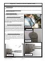
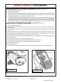
15. DRIVELINE ATTACHMENT:
The driveline yoke and tractor PTO shaft must be dirt
free and greased for easy and secure attachment.
To connect the mower driveline to the tractor PTO output
shaft, pull the driveline yoke collar back and align the
grooves and splines of the yoke with those of the PTO
shaft. Push the driveline yoke onto the PTO shaft,
release the locking collar, and position the yoke until
the locking collar is securely attached to the PTO shaft.
Push and pull the driveline back and forth several times
to ensure a secure attachment.
WARNING!
Do not let the Blades turn when the Mower Deck is raised for any
reason, including clearance or for turning. Raising the Mower deck
exposes the Cutting Blades which creates a potentially serious hazard
and could cause serious injury or even death from objects thrown from
the Blades. (SRM-7)
WARNING! When attaching the Implement input driveline to the Tractor PTO, it is important that the
connecting yoke spring activated locking collar slides freely and the locking balls are seated
securely in the groove on the Tractor PTO shaft. A driveline not attached correctly to the Tractor
PTO shaft could come loose and result in personal injury and damage to the Implement. (S3PT17)
Interstater - Service Manual (03/06)
© 2006 Alamo Industrial
Section 3 - 7
SPECIFICATIONS - INTERSTATER
16.
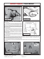
DRIVELINE LENGTH CHECK:
WARNING!
Before operating the Mower, check to make sure the Implement input driveline will not
bottom out or become disengaged. Bottoming out occurs when the inner shaft penetrates
the outer housing until the assembly becomes solid-it can shorten no more. Bottoming
out can cause serious damage to the Tractor PTO by pushing the PTO into the Tractor and
through the support bearings or downward onto the PTO shaft, breaking it off. A broken
drive line can cause personal injury. (S3PT-18)
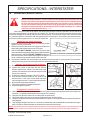
When fitting the mower to the tractor, the telescoping driveline must be inspected to ensure that at its
most compressed position, the profiles do not “bottom out”, and when at its farthest extended position, there
is sufficient engagement between the profiles to operate safely. At its shortest length, there must be at least
a 1” clearance between each profile end and opposite profile universal joint. At its farthest operating extension,
a minimum profile engagement of 12” must be maintained.
“Bottoming Out” Check Procedure:
A. Disconnect driveline from the tractor and slide the profiles
together until fully compressed.
B. Place a mark on the inner shield 1/8” from the end of the outer
shield and reattach the driveline to the PTO shaft.
C. With the PTO NOT TURNING, slowly drive the tractor with
mower attached through the sharpest turn possible and watch
shaft movement. With the PTO NOT TURNING, slowly drive Driveline in maximum compressed position.
the tractor with the mower attached through the most severe
terrain conditions expected and watch shaft movement.
D. If the distance between the mark and the outer shield becomes less than 2” at any point there is a potential
problem bottoming out the driveline and the driveline should be shortened.
"Shorten" the driveline profiles as follows:
A. Remove the driveline from the tractor.
B. Position the mower to the point with the shortest
distance between the tractor PTO shaft and cutter
gearbox. Shut down the tractor and securely block the
mower in this position.
C. Pull driveline apart and reattach yoke to PTO shaft.
D. Hold driveline sections parallel to one another and
measure back 1” from yoke of each shaft and place
mark on opposite section. Cut this length off with a saw.
E. Round off all sharp edges and debur.
F. Thoroughly grease then reinstall the driveline.
G. Recheck for proper operation.
A.
B.
C.
D.
E.
"Engagement" Check Procedure"
With the driveline attached, position the mower to the point where the telescoping driveline is at its maximum
extension. Completely shut down the tractor and secure in position.
Mark the inner driveline shield 1/8” from the end of the outer shield.
Disconnect the driveline from the tractor and separate the two driveline halves.
Measure the distance from the mark to the end of the inner profile. This length is the amount the driveline profiles
were engaged.
If the engaged length is less than 12”, the shaft is considered too short and should be replaced with a longer
shaft. Consult an authorized dealer to purchase the required driveline length.
NOTE: If the driveline cannot be shortened and still maintain the required profile engagement, the operator must be made
aware of terrain conditions and avoid situations which pose a potential problem to avoid damaging the driveline.
Interstater - Service Manual (03/06)
© 2006 Alamo Industrial
Section 3 - 8
SPECIFICATIONS - INTERSTATER
17.
HOSE END FITTING TORQUE SPECIFICATION:
Hose End Type: 37 Degree Angle End Steel Hose End Fittings*
Dash
Nominal Cyl.
Torque
Torque
Size
Size (in.)
in. lbs.
ft .lbs.
-4
1/4"
140
12
-6
3/8"
230
19
-8
1/2"
450
38
-10
5/8"
650
54
-12
3/4"
900
75
-16
1"
1200
100
-20
1-1/4"
1600
133
-24
1-1/2"
2000
167
-32
2"
2800
233
* Straight Threads do not always seal better when higher torgues are used. Too much torque
causes distortion and may lead to leakage. DO NOT over torque fittings and DO NOT allow any
contaminants to enter system through fittings when installing them.
18.
TORQUE VALUES - BOLTS:
Maximum Torque per Bolt Size and Grade, Ft lbs & (Nm)
IMPORTANT ! Listed below IS BOLT TORQUE and NOT APPLICATION TORQUE, Component
Application Torque will vary dependimg on what is bolted down and the type material (Metal) that is
being bolted together. Thread condition and lubrication will vary Torque settings.
Inche Sizes
Bolt
Dia.
inch
1/4
5/16
3/8
7/16
1/2
9/16
5/8
3/4
7/8
1
1-1/8
1-1/4
5 (D)
2 (B)
Metric Sizes
8 (F)
Plain Head 3 Dashes 6 Dashes
Not Used
Not Used
Not Used
35 (47)
55 (75)
75 (102)
105 (142)
185 (251)
160 (217)
250 (339)
330 (447)
480 (651)
10 (14)
20 (27)
35 (47)
55 (75)
85 (115)
130 (176)
170 (230)
300 (407)
445 (603)
670 (908)
910 (1234)
1250 (1695)
14 (19)
30 (41)
50 (68)
80 (108)
120 (163)
175 (230)
240 (325)
425 (576)
685 (929)
1030 (1396)
1460 (1979)
2060 (2793)
ALWAYS
CHECK
MARKINGS
ON
TOP
OF
BOLT
HEAD
OR
OTHER
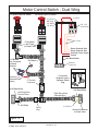
BOLT
DESCRIPTIONS
Interstater - Service Manual (03/06)
© 2006 Alamo Industrial
Section 3 - 9
Bolt
Dia.
mm
6
8
10
12
14
16
18
20
22
24
27
30
33
36
4.8
5
11
20
37
60
92
118
160
215
285
450
600
800
900
8.8
7
20
40
70
100
155
216
270
330
500
875
1200
1600
2100
10.8
12
25
58
105
140
200
280
355
430
700
1000
1700
2300
3000
SPECIFICATIONS - INTERSTATER
Figure 1
If an adapter is attached to the drive of a torque wrench, the wrench will not give actual torque
indicated by the setting of the handle. A simple formula however, allows you to figure out what the
setting should be to deliver a predetermined amount of torque at the end of any adapter to the
fastener.
The following letters are defined as:
A
B
C
D
=
=
=
=
Length of the torque wrench when set at the middle scale setting (inches).
Length of adapter (inches from center hex bolt to center of torque wrench square shaft.
Desired torque at end of extrusion
Setting for accuracy within + or - 6%.
Here is a typical problem. You have an adapter that adds 10.0 inches to a torque wrench
length (dimension B) What should the setting be to obtain 320 ft. lbs. of torque at the end of the
adapter.
A
B
C
D
=
=
=
=
C
=
22.57 inches (length from adapter mounting point torque wrench to center of grip / handle)
10.0 inches (Length from adapter mounting point of torque wrench to center of hex slot).
320 ft. lbs. torque (desired torque at end of extension).
Unknown (setting you need to set torque wrench to = 320 ft. lbs for accuracy).
(A)
(22.57)
(22.57)
------------------- or 320 ----------------------- = 320 ------------------ = 320 X 222 ft. lbs.
(A + B)
(22.57 + 10.0)
(32.57)
Your Answer (D) is a setting of 222 ft. lbs. on the torque wrench will give 320 ft. lbs. of torque at the
bolt. By using the above formula an accuracy of + or - 6 % of the desired torque will result at the end
of the adapter due to length change during grip adjustment.
Interstater - Service Manual (03/06)
© 2006 Alamo Industrial
Section 3 - 10
SPECIFICATIONS - INTERSTATER
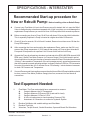
Recommended Start-up procedure for
New or Rebuilt Pump: Before Installing a New or Rebuilt Pump
A.
Connect your Flow Meter in Line to test Pressure as unit is started; this is in case the Relief
Valve is malfunctioning or has been tampered with. If this is not done you could damage the
replacement Pump because you would not Know it till Pump failed from excessive pressure.
B.
Before connecting any lines to Pump, fill all Ports with clean Oil to provide initial Lubrication.
This is especially important is Pump is located at a higher level than Oil Reservoir.
C.
Check Oil level in reservoir, fill to full level if needed, Reservoir must have more Oil than the
Pump GPM capacity.
D.
After connecting the Lines and mounting the replacement Pump, make sure that Oil is not
warmer than Pump temperature. If Oil is warmer than pump run Pump at short intervals till
Pump and Oil temperature is equalized. Hot Oil must not be fed into cold Pump.
E.
Operate the Pump for at least two minutes at no load and at low RPM (400 RPM min and 1400
RPM max.). Watch Flow Meter Pressure (or Pressure Gauge). During this break-in period,
the unit should run free and not develop an excessive amount of heat. Heat should not exceed
100 deg F. above ambient Temperature. If the unit operates properly, speed and pressure can
then be increased to normal operating settings. Increase Pressure in 500 Lbs. PSI increments
from start, this should take 4 to 5 minutes to max. PSI allowing 1 minute between increases
to check Oil Pressure and Temperature.
F.
If normal Pressure and Heat readings are seen then the New or Rebuilt Pump installation should
be done, remove Flow Meter (Pressure Gauge) from line, reconnect Line and check all
connections.
Test Equpment Needed:
1.
Flow Meter, The Flow meter should have components to measure:
A.
Guage to Measure the Oil Temperature.
B.
Gauge to Measure Oil Pressure PSI (Load and No Load).
C.
Gauge to Measure Oil Flow in G.P.M.
D.
A Valve to load system to check operating Pressure (PSI).
E.
Assortment of Connections to connect to Hydraulic System.
2.
3.
4.
Electrical Volt Meter with variable settings and Ohm Meter.
Electrical Test Light.
Wrenches, Torque Wrench, Socket Wrenches, Open and Boxed End Wrenches.
Interstater - Service Manual (03/06)
© 2006 Alamo Industrial
Section 3 - 11
NOTES
Interstater - Service Manual (03/06)
© 2006 Alamo Industrial
Section 3 - 12
Section 4
Interstater
SERVICE MANUAL
Hydraulic & Electrical
Schematics
This section shows the Schematics for
the hydraulic system of the pump, motor
and cylinder circuit. The Schematic for the
electrical Wing Motor Shut Off System
Interstater - Service Manual (03/06)
© 2006 Alamo Industrial
Section 4 - 1
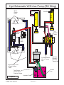
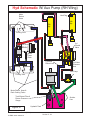
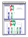
Hyd Schematic W/ Aux Pump (RH Wing)
Motor
Return
Hose
Vent Plug
Tilt
Cyl
Lift
Cyl
Cooling Tube
Cyl
Control
Valve
Motor
Motor
Case
Drain
Cyl Valve
Return Line
Cyl Valve
Pressure
Line
Aux Pump
Cooling Tube
Pump
Motor Return Hose &
Deck Cooling Tanks
Tank Return Filter &
Return Pressure
Gauge
Figure 1
Suction
Line
Hydraulic Tank
Interstater - Service Manual (03/06)
© 2006 Alamo Industrial
Section 4 - 2
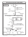
Hyd Schematic W/ Aux Pump (Dual Wing)
Vent
Plug
Vent
Plug
LH Wing
Tilt Cyl.
LH
Wing
Lift
Cyl.
RH Wing
Tilt Cyl.
RH
Wing
Lift
Cyl.
Cyl
Control
Valve
RH Motor
Case Drain
LH Motor
Case Drain
Motor
Cyl Valve
Return Line
Cyl Valve
Pressure
Line
Motor
LH Motor Pressure Line
RH Motor Pressure Line
Cooling Tube
Motor Return Hose &
Deck Cooling Tanks
Cooling Tube
LH
Wing
Pump
Tank Return
Filter & Return
Pressure
Gauge
Aux Cyl. Pump
Suction Line
Pump Case
Drain Lines
Tandem Pump
Suction Lines
Hydraulic Tank
Figure 2
Interstater - Service Manual (03/06)
© 2006 Alamo Industrial
Cyl Valve
Pressure Line
Aux Cyl.
Pump
RH
Wing
Pump
Section 4 - 3
Hyd Schematic W/O Aux Pump (RH Wing)
Motor
Return
Hose
Vent Plug
Lift
Cyl
Tilt
Cyl
Cooling Tube
Cyl
Control
Valve
Motor
Motor
Case
Drain
Cooling Tube
Pump
Cyl Valve Return
Line to Tractor
Hyd
Cyl Valve
Pressure
Line from
Tractor Hyd
Motor Return Hose
& Deck Cooling
Tanks
Suction
Line
Tank Return
Filter & Return
Pressure Gauge
Hydraulic Tank
Figure 3
Interstater - Service Manual (03/06)
© 2006 Alamo Industrial
Section 4 - 4
Hyd Schematic W/O Aux Pump (Dual Wing)
Vent
Plug
Vent
Plug
LH Wing
Tilt Cyl.
LH
Wing
Lift
Cyl.
RH Wing
Tilt Cyl.
RH
Wing
Lift
Cyl.
Cyl
Control
Valve
RH Motor
Case Drain
LH Motor
Case Drain
Motor
Cyl Valve
Pressure
Line
Motor
LH Motor Pressure Line
RH Motor
Pressure Line
Cooling Tube
Motor Return Hose &
Deck Cooling Tanks
Cooling Tube
RH
Wing
Pump
LH
Wing
Pump
Tank Return
Filter & Return
Pressure
Gauge
Pump Case
Drain Lines
Tandem Pump
Suction Lines
Figure 4
Cyl Valve
Return to
Tractor Hyd
Hydraulic Tank
Interstater - Service Manual (03/06)
© 2006 Alamo Industrial
Cyl Valve
Pressure from
Tractor Hyd
Section 4 - 5
Valve to Cylinder Hose Connections (Cab & ROPS)
○ ○ ○
○ ○ ○ ○ ○ ○ ○ ○ ○ ○ ○ ○ ○ ○ ○ ○ ○ ○ ○ ○ ○
Figure 5
○
○
○ ○ ○ ○
○
○
○
○
"T" Tank Return Port
1
11
1
1
RH Wing Only
(Use with Aux. Pump)
○
○
○
○
○
○
Vent
Plug
○ ○ ○
RH Wing
Lift Cyl
○ ○ ○
○ ○ ○ ○ ○ ○ ○ ○ ○ ○ ○ ○ ○ ○ ○ ○ ○ ○ ○ ○ ○
○ ○ ○ ○ ○ ○ ○ ○ ○ ○ ○
○
○
○
○ ○ ○ ○
RH Wing
Tilt Cyl
○
○
○
○
○
○
○
○
○ ○ ○
○1 ○ ○
○ ○ ○
1
1
○ ○ ○
○ ○ ○
○ ○ ○
○ ○ ○
○ ○
1
○ ○ ○ 1
○ ○ ○
○ ○ ○
○ ○ ○
○ ○ ○
○ ○ ○
○ ○ ○
○ ○ ○
○ ○ ○
○ ○ ○
○ ○ ○
○ ○
○
○
Vent
Plug
Vent
Plug
○ ○ ○
RH Wing
Lift Cyl
○
○ ○
○ ○
Dual Wing
(Use with
Aux. Pump)
Interstater - Service Manual (03/06)
© 2006 Alamo Industrial
"T" Tank Return Port
Section 4 - 6
○ ○ ○ ○ ○ ○ ○ ○ ○ ○ ○
12
12
○ ○
○ ○
○
○
○
○
○ ○
○ ○ ○ ○ ○ ○ ○ ○ ○ ○ ○
○ ○ ○ ○ ○ ○ ○ ○ ○ ○ ○ ○ ○ ○ ○ ○ ○ ○ ○ ○ ○
○ ○
12
12 ○ ○
○
○
○ ○ ○ ○ ○ ○ ○ ○
○ ○ ○
○ ○
○ ○
○
○ ○
○ ○
○ ○ ○ ○ ○ ○
○ ○
○ ○ ○ ○
○ ○ ○ ○ ○
Figure 6
"P" Pressure Port
○ ○ ○
LH Wing
Lift Cyl
○ ○ ○
○ ○ ○ ○ ○ ○ ○ ○ ○ ○ ○ ○ ○ ○ ○ ○ ○ ○ ○ ○ ○ ○
RH Wing
Tilt Cyl
○ ○ ○ ○ ○ ○ ○ ○ ○ ○
○
12
12
○
○ ○
○ ○
○ ○ ○ ○ ○ ○ ○ ○ ○ ○ ○
○ ○ ○ ○ ○ ○ ○ ○ ○ ○ ○
○ ○ ○ ○ ○ ○ ○ ○ ○ ○ ○ ○ ○ ○ ○ ○ ○ ○ ○ ○ ○
○
○ ○
○ ○
○
12 ○ ○ ○
12
○
○
○ ○ ○ ○ ○ ○
○ ○ ○ ○ ○
○ ○
○ ○
○
○ ○
○ ○ ○
○ ○ ○ ○ ○ ○ ○ ○ ○ ○
"P" Pressure Port
○ ○ ○ ○ ○
LH Wing
Tilt Cyl
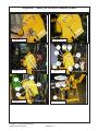
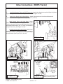
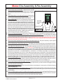
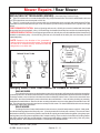
Wire Harness Connections (CAB & ROPS)
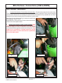
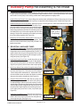
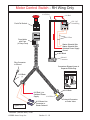
Wire Harness Connections:
1.
Connect Wire Harness to Tractor Starter Activation Wires. The wires to the starter from the motor control
switches will need to be connected to the tractor near the ignition switch connections. Or they can be connected
near the starter solenoid, this is something the technician will need todecide as they assemble the unit. Alamo
Industrial recommends connecting the wires at thetractor ignition switch
(See Figure 7 thru 9 ). Also see the wire / harness schematic on the
following pages. Consult Tractor
Repair Manual for wiring schematic of Tractor to determine what wire
is what on the tractor ignition switch.
2.
Connect Power Supply for Motor Control Switches. Make
certain the battery is disconnected before connecting wires.
The power supply wire must be connected to a wire that only has
current when the tractors ignition switch is in the "ON" position. If the
supply wire is connected to a constant active wire and the
notor control switchs are left on when tractor is parked they
will run the battery down.
Figure 7
Figure 8
Figure 9
Figure 10
Figure 11
Interstater - Service Manual (03/06)
© 2006 Alamo Industrial
Section 4 - 7
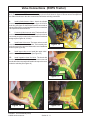
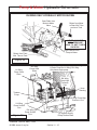
Wire Harness Connections (CAB & ROPS)
3.
Check
all Wire Harness Routing.
Inspect all of
the wire harness before
connecting
them. Make
certain that
all portions of
wire harness
that have
been installed
Figure 12
is tied up and
out of the way
folding components or any thing that may
damage them (See Figure 7 thru 9).
LH Wing Shown
From Front
Figure 13
Battery
ACC
4.
Wires from the safety switch must be
routed close to cutter housing side sheet and
lift frame pivot points. This will prevent wires
from being stretched and broken when cutter
housing is raised or lowered to maximum
positions (See Figure 13)
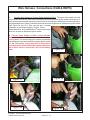
Shown here is typical Ignition connection, Your Ignition may vary but the funcIgnition
Starter
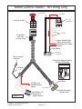
5.
6.
Wire Harness Components. The wire harness will be received in sections. The main wire
harness (Single or dual wings) and the wing
harness, a RH harness and a LH harness. The
RH and LH harness will both be used for a dual
wing unit. and only the RH harness for a single
wing unit.
Tractor
Ignition
Br
ow
nW
Re
dW
ire
of
ire
Ha
of
Br
rne
Ha
ow
ss
rne
nW
ss
ire
Bl
ac
of
kW
Ha
rne
ire
ss
Gr
ou
nd
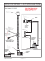
Route Wires for Cut Off Switches. The
wire harnes for the magnetic cut off switches
mounted on the wing hinges will be ran through
a piece of square tubing welded to the lift frame,
this is to protect the wires from be hung up on
object while mowing.
Tr
ac
tor
Ign
itio
nW
ire
Cut
Tractor
Starter Wire to
Starter Solenoid
and
reroute
through Joystick
Harness Brown
FIGURE 14
NOTE: Route wires in such a manner to Motor Control
prevent interference with the operation of tracWiring Hartor or INTERSTATER. Ensure that wires DO
NOT lay against anything which could wear through insulation and cause a short circuit.
After connecting all wires, wrap wires with flex guard tubing. Neatly gather hydraulic hoses and flex guard
tubing and strap together using plastic ties.
Interstater - Service Manual (03/06)
© 2006 Alamo Industrial
Section 4 - 8
Wiring Harness Schematic (CAB & ROPS)
Figure 15
Right
Switch
Left
Switch
DOUBLE WING MOWER
SHOWN
(Single Wings have only the Right
Wing Motor Solenoid Valve
harness)
Brown
Brown
Red
Black
3 Terminal
Connector
Cavity
Plug
Left Wing Motor
Solenoid Valve
Right Wing Motor
Solenoid Valve
White
Black/Wht
Yellow
Black/Wht
Yellow
Fuse
Red
Left
Switch
Red
Right
Switch
Brown
White
Yellow
Brown (Start Terminal)
Brown (Starter Solenoid)
3 Terminal
Connector
Red (to Accessory Terminal)
Black (Ground @ Tractor Starter)
White
Yellow
Left Wing Safety Cut-off Switch
White
Right Wing Safety Cut-off Switch
White
Black
Black
B/W
Left Wing
Motor Solenoid
Valve
Black/White
#1
#2
#1
Black
Interstater - Service Manual (03/06)
© 2006 Alamo Industrial
Section 4 - 9
#2
Right Wing
Motor Solenoid
Valve
Motor Control Switch - Dual Wing
LH Wing Push-Pull Switch
RH Wing Push-Pull Switch
# 16 Red
# 16 Yellow
RH Wing &
#16 White
LH Wing
ON / Off
Switch Plug
# 12 Brn
Fuse Holder
with Fuse
(10 Amp Fuse)
Starter Solenoid Wire
Starter Solenoid Wire
Switched Power Supply
Ground
# 12 Brown
Line Connector
to Starter
Solenoid
#16 Red (+) to
Switched Power
Supply
#16 Black/White
#16 Black (-)
Solenoid
Connector
3 Terminal
Connector
#16 Black/White
Connecters
Shipped Loose in
Separate Plastic
Bag
1234567
1234567
1234567
1234567
1234567
1234567
1234567
1234567
1234567
1234567
1234567
Left Wing Motor
Solenoid Valve
#16 Black/White
Right Wing Motor
Solenoid Valve
#16 White
# 16 Yellow
Cavity
Plug
Solenoid Connector
at Cutter Valve
Figure 16
Interstater - Service Manual (03/06)
© 2006 Alamo Industrial
Section 4 - 10
Motor Control Switch - RH Wing Only
# 16 Yellow
# 16 Red
ON / Off
Switch Plug
Push-Pull Switch
# 12 Brn
Fuse Holder
with Fuse
(10 Amp Fuse)
Starter Solenoid Wire
Starter Solenoid Wire
Switched Power Supply
Ground
#16 Black
Solenoid
Connector
Ring Connector
to Ground
Connecters Shipped Loose in
Separate Plastic Bag
#16 Black
(-)
#16 Black
#16 Red (+) to
Switched Power
Supply
# 16 Yellow
Figure 17
# 12 Brown Line
Connector to
Starter Solenoid
Interstater - Service Manual (03/06)
© 2006 Alamo Industrial
Section 4 - 11
Solenoid Connector
at Cutter Valve
Wing Wire Harness - R-Wing (Single Wing)
Wire Harness P/N 002496
Cap Connector
used on RH
Only Wing
1234567890
1234567890
1234567890
Note: RH Wing Only (Single
Wing) will use P/N 002496 Wire
Harness only
Connector
to Main Harness
White
To LH Wing
or Plugged
123
123
123
123
123
123
123
123
123
123
123
123
123
123
123
123
123
123
123
123
123
Connector
to Main
Harness
Yellow (+)
(Outer Connector - Connects to White Wire)
Black
Yellow (+)
Wires connect
to wing magnet
switch
Black / White (-)
Black / White (-)
(Inner Connector Connects to Black Wire)
Connector to
Wing Motor
Solenoid
Connector
Gasket
Schematic P/N 002496
1234567890123
1234567890123
1234567890123
1234567890123
1234567890123
1234567890123
1234567890123
1234567890123
1234567890123
1234567890123
1234567890123456
1234567890123456
1234567890123456
Figure 18
Interstater - Service Manual (03/06)
© 2006 Alamo Industrial
Connector to
Wing Motor
Solenoid
Section 4 - 12
Connector
Fastening
Screw
Wing Wire Harness - L & R-Wing (Dual Wing)
Wire Harness P/N 002497
Connector
to Main Harness
Note: Dual Wing will use
both P/N 002496 & P/N
002497 Wire Harness
12345678901
12345678901
12345678901
Connector
to Main Harness
White
12
12
12
12
12
12
12
12
12
12
Connector
to Main
Harness
White (+)
(Outer Connector - Connects to White Wire)
White (+)
Wires connect
to wing magnet
switch
Black / White (-)
Black / White (-)
(Inner Connector - Connects to Black Wire)
Connector to
Wing Motor
Solenoid
Connector
Fastening
Screw
12345678901234567
12345678901234567
12345678901234567
Schematic P/N 002496
12345678901234
12345678901234
12345678901234
12345678901234
12345678901234
12345678901234
12345678901234
12345678901234
12345678901234
12345678901234
Figure 19
Interstater - Service Manual (03/06)
© 2006 Alamo Industrial
Connector to
Wing Motor
Solenoid
Section 4 - 13
Connector
Gasket
Black
Pump & Motor Hydraulic Schematic (RH Wing Only)
Pressure Hose From Pump has
a 90° Fitting Connects here.
Pressure Hose Motor has
a 90° Fitting Connects here.
NOTE: The Pressure hose will
always be connected to the top
fitting and the return will always
connect to the bottom.
123
123
123
123
123
123
123
123
123
123
123
123
1234
1234 123
1234
1234
1234
cccccccccccccccccccccc
Return Hose from Cutter Head
Cooling Tanks has a 45° Fitting
Connects here.
Return Hose to Tank Return Filter
has a 90° Fitting Connects here.
Main Frame w/ hose bulkhead fitting
RH side of tractor looking from front to rear of tractor
Single Wing Shown, Dual Wing has metal cross over pipe with a Tee in it for the return.
Figure 40
Note 45° elbow on
bulkhead fitting tha
hose connects to
Figure 41
Interstater - Service Manual (03/06)
© 2006 Alamo Industrial
Section 4 - 14
Pump & Motor Hydraulic Schematic (Dual Wing)
TRACTOR
REAR
Return to Tank from
Wet Tubes of RH Wing
RIGHT WING
T
OU
Return
Line
Tee
Return to Tank from
Wet Tubes of LH Wing
Mainframe
Tube Cross Over
LEFT WING
Hose Sleeving
OUT
Hose Sleeving
IN
IN
Pressure from Pump
to RH Wing Motor
OUT
Pressure from Pump
to LH Wing Motor
TRACTOR
LH SIDE
TRACTOR
RH SIDE
IN
Indicates
Direction of
Flow
IN
Hose Sleeving
Return to Tank from
Wet Tubes of RH & LH
Wing
Pressure from Pump
to RH Wing Motor
Figure 42
TRACTOR
FRONT
Interstater - Service Manual (03/06)
© 2006 Alamo Industrial
Section 4 - 15
Pressure from Pump
to LH Wing Motor
Pump & Motor Hydraulic Schematic
RH WING ONLY HYDRAULIC MOTOR SHOWN
Case Drain from
Motor to Motor
Valve
Return from Motor
to Rear Wet Tube
and on to Tank
NEVER CONNECT
HIGH PRESSURE
HOSE TO WET TUBES
ON DECK !
High Pressure from
Pump to Motor
Return from Front
Wet Tube to Tank
Figure 43
RH Wing
Pump Case
Drain
LH Wing
Pump Case
Drain
Tandem Pump, Inner Pump for RH Wing
& Outer Pump for LH Wing. RH Wing
Only has a single pump.
RH Wing
Pump High
Pressure
Line
Hose
Sleeving
Tandem
Pump
LH Wing Pump High
Pressure Line
LH Wing
Pump Suction
Line
Figure 44
RH Wing
Pump Suction
Line
Cyl System Supply
Pump Suction Hose
Interstater - Service Manual (03/06)
© 2006 Alamo Industrial
Section 4 - 16
Pump & Motor Hydraulic Schematic
Tank Return Filter Assembly
& Tank Return Pressure
Gauge
Tank Return Hose from
Cylinder Control Valve
to Tank
Tank Return Hose from
Wet Tubes on LH &
RH Wing Decks
Oil Level
Sight
Glass
Oil Temperature
Gauge
Figure 45
Upper Connection Always
from Pump To Wing Motors
NEVER TO WET TUBES
(HIGH PRESSURE)
Main Frame Cross Over
Bracket & Tubes (RH
Side Shown, note Tee
Fitting in lower fittings
Lower Connection Always
from Deck Wet Tubes to
Filter Tank Return Line
(LOW PRESSURE)
Nut on Bulkhead Fittings
Figure 46
Interstater - Service Manual (03/06)
© 2006 Alamo Industrial
Section 4 - 17
Pump & Motor Hydraulic Schematic
Wings have a front and a
rear wet tube for cooling
the oil. At the outer end of
the decks there is a cross
over hose which allows the oil to cross from the rear
tube to the front tube,The Tubes and the cross over
hose are in the oil return to tank circuit which has to
be low pressure..
Figure 47
Hoses for the
Lift and Tilt
cylinders are
the same size
Qty 3 of Hose
P/N 02905100
(#4 - 4FJX 4FJX X 114"
Long
○
○ ○ ○ ○
○ ○ ○ ○ ○ ○ ○ ○ ○ ○ ○ ○ ○ ○
○
○ ○ ○ ○ ○ ○ ○ ○
○
○
○
○
○
○ ○
○
○
○ ○
○
○
○
○ ○
○ ○
○
○ ○
○ ○
○
○ ○ ○ ○ ○ ○ ○ ○ ○ ○ ○ ○ ○ ○ ○ ○ ○ ○
Tractor Remote
Hyd Outlets.
RH Wing
Tilt Cylinder
○
○
○
○ ○ ○
○
○
Vent
Plug
Make certain lift
control spacer was
installed on Lift cyl,
See Figure 12 & 13
Connecting Cylinders To
Tractor Control Valve for Hydraulic Supply.
When the tractor hydraulics are
used to supply and operate the cylinders
there will not be a control valve shipped
with the mower. The hydraulic cylinders
will connect direct to the tractors remote
outlets and the tractor controls will be
used (See Figure 14).
When using the Auxiliary front
pump for the cylinder hydraulic system
there will be a control valve and components shipped. See the section for installing the auxiliary pump and control valve.
RH Wing
Lift Cylinder
Figure 48
Interstater - Service Manual (03/06)
© 2006 Alamo Industrial
Section 4 - 18
Section 5
Interstater
SERVICE MANUAL
Hydraulic Pumps
Tandem - Single - Auxiliary
Remove - Repair - Replace
Interstater - Service Manual (03/06)
© 2006 Alamo Industrial
Section 5 - 1
Tandem & Single Pump Removal
GENERAL PUMP REPAIR / REPLACEMENT INFORMATION:
A. To disassemble / repair your INTERSTATER this manual is designed to assist you with drawings, instructions
B.
C.
D.
E.
F.
G.
H.
I.
and information. This manual is designed to be used in conjunction with the parts manual, operators manual
and the assembly manuals. If additional information or clarification is needed contact your Alamo Industrial
factory representative.
Some of these instructions are general information and not specifically for your tractor, but in connection with
our drawings, they may not show the exact application and tractor you have. In many cases to assembly
manual for your mower to tractor application will clarify some clarity to exact applications.
This section covers the removal, repair and reinstallation of the hydraulic pump procedure for the Alamo
Industrial Interstater mower, it also includes instruction for driveshaft, hoses, and miscellaneous parts to be
attached the hydraulic pumps to the tractor.
These instructions are for working on the pumps used to power wing mower/mowers, right side mower, and
left side mower units if dual wing model. For mounting one mower side only, disregard information concerning
the opposite side. Hardware quantities shown are for both sides.
The Auxiliary pump is used to supply the lift and tilt hydraulic cylinder circuit. This auxiliary pump will not
be used on all units, some will use the tractor hydraulic system to supply cylinder circuit.
Reference to the left or right side of the Interstater is determined while facing the front of the tractor from the
drivers seat.
The part quantities shown for an illustration pertain only to that phase of repair. The quantity given corresponds
to the number of parts needed. When repairing a single-sided model based on a dual-sided model, the quantity
furnished will usually be half the quantity listed.
Large parts may not always be listed next to an illustration because they are usually easy to identify them
from name or description.
This manual makes reference to individual component parts, some of which may have been pre-assembled
at the factory.
Abbreviation of Parts Terminology :
Whenever reference is made to parts, listed for an illustration or elsewhere in this manual, the following
abbreviations may be used:
1.
ASY - Assembly
2. ASSY - Assembly
3. AUX - Auxiliary
4.
BRG - Bearing
5. BRKT - Bracket
6
CYL - Cylinder
7.
CW - Clockwise
8. CCW - Counter Clockwise
7. EXT - Extreme
8.
EXT’N - Extend / Extension
9. F/ - For or From
10. FM - Female Boss
11.
FP - Female Pipe
12. FSTNR - Fastener
13. FT - Foot / Feet
14.
GB - G/B - Gearbox
15. GR - Grade
16. HD - Heavy Duty
17.
HHCS - Hex Head Capscrew
18. HRDND - Hardened
19. HYD - Hydraulic
20.
IN - Inch
21. LB - Pound
22. LH - Left Hand
23.
LW - Lock Washer
24. M - Metric
25. MB - Male Boss
26.
MM - Millimeters
27. MNT - Mount
28. MP - Male Pipe
29.
MTR - Motor
30. N/A - Not Applicable
31. NC - National Coarse
32.
NF - National Fine
33. NLA - No Longer Available
34. NLF - No Longer Furnished
35.
NPT - National Pipe Thread
36. P1.5 - Thread Pitch
37. P2.0 - Thread Pitch
38.
P2.5 - Thread Pitch
39. PL - Plated
40. PLT - Plate
41.
PMP - Pump
42. PTO - Power Take Off
43. PW- Plain Washer
44.
REV - Reverse
45. RH - Right Hand
46. ROT - Rotation
47.
RPM - Revolutions Per Minute
48. SCKT - Socket
49. SD - Severe Duty
50.
SRV - Service
51. STD - Standard
52. SVR - Severe
53.
W/ - With
54. W/O - With Out
55. WLDMNT - Weldment
When installing fasteners, PW and LW (generally installed in that order) are usually on the side of the
fixture or part being fastened that the hex/lock nut is on. When only HHCS, LW and/or PW are required, they
are generally installed in that order. Some parts do not require a PW or LW. Refer to illustrations for exceptions.
Fasteners should be installed so they cause the least interference with other parts. When securing driveshaft
pulley to hub, tighten fasteners to 9 lb-ft torque.
Interstater - Service Manual (03/06)
© 2006 Alamo Industrial
Section 5 - 2
Tandem & Single Pump Removal
1. INTRODUCTION:
In Most diagrams there are no Component Part Numbers Listed, Only Item numbers and Descriptions, This
is because most parts shown as breakdown in drawings are for location, identification or if available as parts.
Replacement parts will be listed in the Parts/Operators/ Asy Manual. This Manual is designed to be used with
these other manuals.
2. BEFORE STARTING REPAIRS: Service Rules (READ THIS)
A. Remove Front Cover. Clean Pump and surrounding area completely before removing any connections or
Lines. NO DIRT OR DEBRIS CAN BE ALLOWED ON OR NEAR HYDRAULIC SYSTEM IF IT IS BEING
WORKED ON, ANY DIRT OR CONTAMINANTS IN SYSTEM NO MATTER HOW SMALL WILL DAM
AGE SYSTEM! The hydraulic system must be kept "SURGICALLY CLEAN" to ensure proper operation and
long life of the pumps, motors, and valves. All components must have protective caps over openings
connected to internal spaces to prevent contamination. It is important that care be taken during unpacking
parts and assemblies to make certain no other contaminants which will damage parts are introduced to
hydraulic system.
B. After cleaning around all connections thoroughly, Disconnect all connections, Lines, Hoses, Wiring and
Remove the Pump Completely from the Tractor.
C. Clean all Tools, Pans etc. The cleaning of Area and Tools MUST be done before moving (Cleaned) Pump
there. Drain Oil from Pump, Recheck outside of Pump to Make Sure it is Clean before disassembly.
D. After disassembly of Pump wash all metal components in clean solvent.
E. Use compressed Air to dry parts after washing (Compressed air must be filtered and moisture free). DO NOT
wipe them dry with Paper Towels or Cloth as these will leave lint and/or dust contamination. DO NOT USE
Compressed Air to spin any component (Such as Bearings or Plates) as this will damage them and could
be dangerous.
F. Always use new Seals when reassembling Hydraulic Pumps, Lubricate the new rubber Seals with a
Petroleum Jelly, (Vaseline) which will hold them in place during assembly.
G. DO NOT reinstall worn/damaged Parts in Pump, DO NOT Use a worn/damaged Pump Housing.
H. Torque all Bolts over Gasketed Joints. Then repeat the Torque sequence to make sure Bolts are tight, some
times Gaskets can give a Torque reading that is OK but is not, so always recheck Torque.
I. Verifying the accuracy of Pump Repairs on an authorized test stand is essential.
J. DO NOT start the tractor unless the hydraulic system is filled with hydraulic oil, all components have been
connected and all safety equipment hase been reinstalled. Running without oil will damage the pumps and
hydraulic system. Check the oil level in the reservoir before start-up after repair.
K.. Care should be taken when filling the reservoir to prevent contamination of the hydraulic system. Always
use new hydraulic fluid when filling the system. USE ONLY APPROVED HYDRAULIC OIL IN THE
HYDRAULIC SYSTEM.
3. RECOMMENDED TOOLS:
A. Hex Allen Wrench (Qty 5) (9/16", 5/32", 5/16", 3/32", 5/64"
B. Retaining Ring Pliers (Qty 3), 1 each of Internal (Straight .070 tip) internal (Straight .090 tip) & 1 each External
(Straight 0.90 tip)
C. Retaining E-Ring Applicator (Qty 2), 1 each 9/32" & 1 each 1/2".
D. O-Ring Pick (Qty 1)
E. End Wrench (Qty 4), 1 each of 7/16", 9/16", 3/4", 1"
F. Torque Wrench (Qty 1), 0 to 100 ft. lbs. (135.6 nm) capacity
G. Hammer, Soft Face (Qty 1)
H. Seal Driver Set (Qty 1)
I. Arbor Press (Qty 1)
J. Sockets (Qty 3) 7/16", 9/16", 3/4" , Drive Size should match Torque Wrench Drive)
K. Light Petroleum Jelly (Vaseline)
L.. Locktite, # 222 and #277 or equivalent (Qty 1 tube each)
M. Petroluim Jelly (Vasoline) Samll Jar
Interstater - Service Manual (03/06)
© 2006 Alamo Industrial
Section 5 - 3
Tandem & Single Pump Repair / Replace
3A.
SPECIAL TOOLS AVAILABLE:
Special tools, for installing and servicing INTERSTATER kits, are illustrated on the below. Drawings for
these tools are available on request. If desired, tools may be obtained from Alamo on a made to order basis.
Prices will be furnished on request.“
Item Part No. Code Description
1
701628 S
Lift Frame Asy Suspension Chain
2
701627 A
Cuttershaft Brg Puller
3
104764 A
Lift Frame Alignment Pin (2)
4
104768 A
Rubber Bushing Support Base
5
104767 A
Rubber Bushing Compression Ring
6
104765 A
Rubber Bushing Expander
(f/ Ford & Kubota Tractor)
7
104766 A
Rubber Bushing Expander
(f/ Case I.H., MF & Case Tractors)
8
104769 A
Drive Shaft Installation Collar
9
104770 A
Rubber Bushing Installation Plug
10 103741 A
Seal Installation & Seating Tool
000802 S
Hyd. Pressure Gauge, 3000 PSI
Figure 1
A - Denotes special tools designed by Alamo.
S - Denotes std tools / equipment available on market
4. RECOMMENDED GAUGES FOR DIAGNOSTICS:
A. Inlet Vacuum: 30 PSI to 30 in Mercury (207 bar to 0 bar)
B. System Pressure Gauge: 6,000 PSI (700 bar)
C. Charge Pressure Gauge: 0 to 500 PSI (0 to 25 bar)
5.
POWER CIRCUIT:
The pump unit assembly is made up of the oil reservoir,
and hydraulic pump. The pump is driven by the engine
crankshaft through a drive shaft. Therefore, oil is being pumped
whenever the engine is running. When the mower is off, oil is
directed to the reservoir by the solenoid motor control valve
and does not flow to the cutter motor. Cooling is provided by
patented in frame cooling tubes in the wing mowers.
6.
PUMP TYPE:
The pump unit for the wing mower rotorshaft drivepower
circuit is a piston fixed displacement pump (see pump repair)
and is engine driven. It is mounted on the front of the tractor
FIGURE 2
above the hydraulic reservoir. There is a separate pump for each
wing. By following the hose routing, the operator can determine
each wing mower's supply source. Each pump has a case drain to eliminate excessive fluid in the pump. All excess
fluid in the pump is routed back to the hydraulic reservoir through the case drain.
Hydraulic reservoir: There is a separate pump for each wing, Tandem for dual wings and single pump for single
wings.. By following the hose routing, the operator can determine each wing mower's supply source. Each pump has
a case drain to eliminate excessive fluid in the pump. All excess fluid in the pumps is routed back to the reservoir through
the case drain.
7.
TYPE PUMP CONFIGURATIONS USED:
There are different configurations of pumps used depending on how mower unit was ordered and how it is
being used on the tractor as weel as which tractor. All Below will used the same hydraulic tank which means not
all ports on hydraulic tank will be used, some will remained plugged. The connections on the tank will remain the
same for the connections needed, leave all ports plugged until ready to connect the fittings.
Interstater - Service Manual (03/06)
© 2006 Alamo Industrial
Section 5 - 4
Tandem & Single Pump Repair / Replace
A. Tandem Pump with Auxiliary Hydraulic Pump, The Tandem Pump is used for the dual wing model
B.
C.
D.
E.
mower and the auxiliary pump is used to supply the hydraulic cylinders and cylinder control valve.
(See Hydraulic Schematic at end of this section)
Tandem Pump without Auxiliary Hydraulic Pump, The Tandem Pump is used for the dual wing model
mower and the tractors hydraulics are used to supply the hydraulic cylinders and cylinder control
valve. (See Hydraulic Schematic at end of this section)
Single Pump with Auxiliary Hydraulic Pump, The Single Pump is used for the Single wing model
mower and the auxiliary pump is used to supply the hydraulic cylinders and cylinder control valve.
(See Hydraulic Schematic at end of this section)
Single Pump without Auxiliary Hydraulic Pump, The Single Pump is used for the dual wing model
mower and the tractors hydraulics are used to supply the hydraulic cylinders and cylinder control
valve.(See Hydraulic Schematic at end of this section)
Pumps with different Cubic Inch Displacement (CID). There are two size pumps used a 2.28 CID pump
and a 2.77 CID pump. The Higher 2.77 CID pump is used on tractors that operate with a lower RPM
engine speed (2000 RPM and below) to acheave PTO Speed, Tractor using 2000 RPM and above use
the larger 2.77 CID Pump are tractor that use a High Engine RPM (above 2000 RPM ) to achieve the
PTO Speed will us the lower 2.28 CID pump. DO NOT use the 2.77 CID pump on tractors with higher
than 2000 RPM engine speed. (See Below for ID numbers that will be stamped on pump flange).
Flange No.
=
Asy No. Description
73498-LAA-01............ =...... 001840.....Inner Pump Section 2.77 CID (Closest to Engine)
73425-LAA-01............ =...... 001734.....Inner Pump Section 2.28 CID (Closest to Engine)
73428-LAG.................=...... 001841.....Outer Pump Section 2.77 CID (Furthermost from Engine)
73425-LAB-01............=...... 001733.....Outer Pump Section 2.28 CID (Furthermost from Engine)
73428-LAF................. =...... 00755650.Single Pump 2.77 CID
73425-LAC.................=...... 001827.....Single Pump 2.28 CID
8.
TYPE HYDRAULIC RESERVOIR USED: The Hydraulic reservoir for the Interstater is the same
for the Tandem Pump (Dual Wing Model) or the Single Pump (Single Wing Model) . When the Single Pump is
being used some of the ports on the tank are not used and will remained plugged.
9.
DRAIN HYDRAULIC RESERVOIR:
Secure Tractor so it cannot be
started while repairing the pump. It will require the oil to be drained form the system
and the tractor MUST NEVER be started
without proper level of oil in the system
To drain the tank it is recommended
that only a filter buggy be used if you intend
on reusing the oil. Filter buggies or carts
are commercially available for hydraulic system clean-up. These consist of a highefficiency, high-capacity filter, a circulating
pump, a drive motor, and hoses for connecting the overhauled machine’s hydraulic system (See Figure 3)
When disposing of or storing removed oil make certain oil to be used is
properly stored to keep it clean and in a
clean container. Make certain Oil that is to
be disposed of is done by following your
local regulations and laws
FIGURE 3
10. REMOVE PUMP COVER:
Remove the Pump Cover by unscrewing the four thumb screws which hold it in place, lift cover upward and off.
If the area under this cover is dirty it must be cleaned before any dissembling starts, this will include all metal
surfaces, hoses and hose fittings. (See Figure 2)
Interstater - Service Manual (03/06)
© 2006 Alamo Industrial
Section 5 - 5
Tandem Pump w/ Tank & Aux Pump
12
19
18
17
16
15
6
13
14
7
11
3
7
5
6
1
10
4
2
5
2
8
4
10
9
Item
1
2
3
4
5
6
7
8
9
10
11
12
13
14
15
16
17
18
19
Qty
1
1
1
1
1
1
1
1
1
1
1
1
1
1
1
1
1
1
1
Description
Hydraulic Tank and Pump Cover Weldment
Tandem Pump Asy, Outer Half LH Wing, Inner Half RH Wing
Auxillary Pump Asy
Suction Hose F/ Tank to LH Wing Pump
Suction Hose F/ Tank to RH Wing Pump
Case Drain Hose F/ LH Wing Pump to Tank
Case Drain Hose F/ RH Wing Pump to Tank
Pressure Hose to LH Wing Motor
Pressure Hose to RH Wing Motor
Suction Hose to Auxilliary Pump
Pressure Hose F/ Auxillairy Pump to Cyl Control Valve
Return Hose F/ Cylinder Control valve to Tank Return Filter
Return Hose F/ Wing Motors to Tank Return Filter
Hydraulic Tank Temperature Gauge
Hydraulic Oil Level Sight Glass
Hydraulic Tank Breather Filler Cap
Hydraulic Tank Filler Cap
Hydraulic Oil Return Pressure Gauge
Hydraulic Oil Return Filter Asy.
Figure 4
Interstater - Service Manual (03/06)
© 2006 Alamo Industrial
Section 5 - 6
Single Pump w/ Tank & Aux Pump
12
18
19
17
16
15
13
14
7
3
11
10
1
4
7
Item
1
2
3
4
7
9
10
11
12
13
14
15
16
17
18
19
Qty
1
1
1
1
1
1
1
1
1
1
1
1
1
1
1
1
10
4
2
Description
Hydraulic Tank and Pump Cover Weldment
Single Pump Asy, RH Wing
Auxillary Pump Asy
Suction Hose F/ Tank to RH Wing Pump
Case Drain Hose F/ RH Wing Pump to Tank
Pressure Hose to RH Wing Motor
Suction Hose to Auxilliary Pump
Pressure Hose F/ Auxillairy Pump to Cyl Control Valve
Return Hose F/ Cylinder Control valve to Tank Return Filter
Return Hose F/ Wing Motors to Tank Return Filter
Hydraulic Tank Temperature Gauge
Hydraulic Oil Level Sight Glass
Hydraulic Tank Breather Filler Cap
Hydraulic Tank Filler Cap
Hydraulic Oil Return Pressure Gauge
Hydraulic Oil Return Filter Asy.
Figure 5
Interstater - Service Manual (03/06)
© 2006 Alamo Industrial
9
Section 5 - 7
Tandem Pump & Driveshaft Asy w/ Aux Pump
Aux Hyd Pump
(Cyl Circuit)
Drive
Belt
Driven
Pulley
Shield
Used on Models with Dual Wings and
Auxillary Hydraulic Pump for Cylinder
Hydraulic Supply (Cyl circuit).
1234
1234
Pulley Adapter
Mounting Bolts
Locknut
Tractor Engine
Pulley
12345
12345
12345
Mounting
Bolt & Washer
* Bearing
Collar
Driveshaft
** Pump
Mount
Plate
Drive Pulley &
Splined Sleeve
Weldment
Pulley
Adapter
* Driveshaft
Bearing
** Small (Cyl Hyd) Pump Mount Plate mounts here
Tandem Pump for Dual Wings
Pump Mount
Weldment
12
12
12
12
Left Wing Pump
123456
123456
123456
Right Wing Pump
Figure 6
Interstater - Service Manual (03/06)
© 2006 Alamo Industrial
Section 5 - 8
* Driveshaft Bearing installs into
pump mount weldment here.
Tandem Pump & Driveshaft Asy w/o Aux Pump
Used on Models with Dual Wings Hydraulic Supply. Tractor hydraulic
supply used for cylinders and cylinder control valve (Cyl circuit).
Pulley Adapter
Mounting Bolts
Tractor Engine
Pulley
Driveshaft
* Bearing
Collar
Splined Sleeve
Pulley
Adapter
* Driveshaft
Bearing
** Small (Cyl Hyd) Pump Mount Plate mounts here
Tandem Pump for Dual Wings
Pump Mount
Weldment
12
12
12
12
Left Wing Pump
123456
123456
123456
123456
Right Wing Pump
Figure 7
Interstater - Service Manual (03/06)
© 2006 Alamo Industrial
Section 5 - 9
* Driveshaft Bearing installs into
pump mount weldment here.
Single Pump & Driveshaft Asy w/ Aux Pump
Aux Hyd Pump
(Cyl Circuit)
Drive
Belt
Driven
Pulley
Shield
Used on Models with Single Wing and
Auxillary Hydraulic Pump for Cylinder
Hydraulic Supply (Cyl circuit).
123
123
Pulley Adapter
Mounting Bolts
Locknut
Tractor Engine
Pulley
12345
12345
12345
Mounting
Bolt & Washer
* Bearing
Collar
Driveshaft
** Pump
Mount
Plate
Drive Pulley &
Splined Sleeve
Weldment
Pulley
Adapter
* Driveshaft
Bearing
** Small (Cyl Hyd) Pump Mount Plate mounts here
Single Pump for One Wing
Only
Pump Mount
Weldment
12
12
12
12
123456
123456
123456
123456
Right Wing Pump
(Most Common)
Figure 8
Interstater - Service Manual (03/06)
© 2006 Alamo Industrial
Section 5 - 10
* Driveshaft Bearing installs into
pump mount weldment here.
Single Pump & Driveshaft Asy w/o Aux Pump
Pulley Adapter Mounting Bolts
Splined Sleeve
Driveshaft
* Driveshaft
Bearing
* Bearing
Collar
Pulley
Adapter
** Small (Cyl Hyd) Pump Mount Plate mounts here
Single Pump for One Wing
Only
Right Wing Pump
(Most Common)
Used on Models
with Single Wing and
Tractor Hydraulic
for Cylinder Hydraulic Supply (Cyl circuit).
Figure 9
Pump Mount
Weldment
12
12
12
12
123456
123456
123456
* Driveshaft Bearing installs into pump mount weldment here.
Interstater - Service Manual (03/06)
© 2006 Alamo Industrial
Section 5 - 11
Tractor
Engine
Pulley
Tandem & Single Pump Remove / Replace
IMPORTANT WARNING !
Once the pump removal process is started tractor CANNOT be started unless both pumps and pump
driveshaft is removed. It is the responsibilty of the repair technician to secure the tractor to where is safely
secure before beginning any repairs. It is recommended that the battery cables be disconnected and a
note "DO NOT START" be place in the tractor operators compartment to prevent others from stating it. IF
the tractor is started with pumps patially disconnected or drive shaft left in the tractor when tractor is
started it will damage the tractor and/or other components.
11. REMOVE PUMP (Pump For Motor Supply): (See Figure 4 through 16)
If both pumps are to be removed for this repair, remove both pumps together and disassemble them on the work
bench is best. If only the outer pump is to be removed it can be removed and the inner pump left mounted. NOTE:
When Unit was originally assembled the technician may have used a pipe sealer in the NPT fitting, Use
caution when removing these that the sealer doesn't fall into the hydraulic system or any of it ports. Clean
all oil spills at once. Cap all hoses immediately to prevent contamination of the hydraulic system.
Remove Outer & Inner Pump From Mower / Tractor:
A. Disconnect the outer Pump Suction Hose (item 4 Figure 4), this hose is retained with hose clamps. It is easier
to remove the fitting at the pump than the hose clamp. Cap all hoses and pump ports immediately.
B. Disconnect the Outer Pump Case Drain Hose (item 6 Figure 4) at the pump fittings. . Cap all hoses and pump
ports immediately.
C. Disconnect the Outer Pump pressure hose (item 8 Figure 4) at the pump. . Cap all hoses and pump ports
immediately.
D. Remove the two bolts which attach the outer pump (item 2 figure 4) to the inner pump flange, Remove the outer
pump by pulling outward on it. Once outer pump is removed cover the opening between the two pumps to keep
it clean.
E. If repairing pump go to pump repair section for pump repair procedures. If installing a new pump or rebuilt pump,
lightly oil new "O" Ring and place on inner pump flange. Install the new pump / rebuilt pump with the pump drain
ports facing Hydraulic Tank (Right hand side of tractor). With your hands push the outer pump into the inner pump
until the two pump flanges are touching, align the two flange bolt holes and install the retaining bolts. CAUTION:
When working with aluminum castings DO NOT force these pumps together with the bolt, it will damage the
pumps.
F. Reinstall hydraulic hoses (item 4, 6 & 8 Figure 4). Tighten hose fittings to their proper torque. Refer to Torque
Chart. in specifications section.
G. If only the outer pump is being replace or repaired fill system with proper type and amount of oil. Run Unit and
check for leaks. Reinstall Pump Cover and tighten the four thumb screws securely.
Auxiliary Pump
Suction Port
Pump Case
Drain To Tank
Pressure Port
(RH Wing Motor)
Auxiliary Pump
Pressure Port
Auxiliary Pump
Suction Port
Leave Capped
on RH
Only Model
Case Drain
To Tank
Pressure Out
Port To RH
Wing Motor
Dual
Wing
Case Drain
From Pump
Suction Port
From Tank
Figure 10
Pressure Port
(LH Wing Motor)
Figure 11
Interstater - Service Manual (03/06)
© 2006 Alamo Industrial
Section 5 - 12
Suction Port
From Tank
Single
Wing
Tandem & Single Pump Remove / Replace
Replace Outer & Inner Pump to Mower / Tractor: (See Figure 4 through 16)
A. To replace or rebuild inner pump, both inner and outer pumps must be removed from tractor. Follow same
procedure as for outer pump above plus instruction for inner pump below. NOTE: Clean spills at once. Cap all
hoses immediately to prevent contamination of the hydraulic system.
B. Separate the outer pump from the inner, This is done by disconnecting hoses to inner pump (item 5, 7 and 9
Figure 4 & 5). Remove the tow bolts holding the outer pump the inner pump or they can be left together and
unbolted on the work bench. Remove the two retaining bolts that mount the pump/ pumps to the pump mount
plate.
C. The pump will slide out of the pump mount plate, the driveshaft may slide back with it or it may stay in tractor,
the splined coupler that connects the pump to the driveshaft may stay on driveshaft or it may stay on pump.
D. Check driveshaft, crankshaft pulley adapter & splined coupler for wear and condition. If any of these parts are
to be changed it is important to check the length of the new and old part to make certain they are the same.
Do Not use coupler, pulley adapter or driveshaft that is worn or damaged, Do Not use driveshaft that is to long
or to short.
E. Make certain that driveshaft is installed into crankshaft pulley adapter correctly. Make certain drive shaft is
inserted through driveshaft bearing and lock collar correctly. Make certain spline coupler or splined coupler pulley
weldment (w/ Auxiliary Pump) is installed correctly, Note: do not tighten auxiliary pump pulley to driveshaft until
later.. Make certain that auxiliary pump drivebelt is installed on pulley (if Auxiliary pump is used).
F. If the pump is to be repaired see pump repair section. If pump is being replaced, bolt the inner and outer pump
together on the bench or bolt inner pump to pump mount plate and then bolt the two pumps together (Dual Wings
w/ Tandem Pump) Install new pump to inner pump making certain both case drain ports are facing hydraulic
reservoir (RH Side of Tractor).
G. Reconnecting hoses to the two pumps (or SinglePump Single Wing). Connect the case drain hose and the pump
pressure hose first. The suction hose port will have an elbow connected to it. Fill this elbow with new clean
hydraulic oil before connecting the hose, this will prevent pump from starting dry when tractor is started later.
H. Fill the hydraulic system with oil to the correct level, always use a 10 micron (max) filter system to install oil. Filter
buggy system are commercially available. Inspect oil sight gauge and temperature gauge to make certain they
are not damaged. Start Tractor and run system checking for leaks.
I. Return Filter pressure gauge, watch the return filter gauge. When the oil is cold the gauge may show in the red
and as oil gets up to normal operating temperature the gauger should drop to the green zone. If gauge pressure
doesn't drop to green zone, check filter for being plugged and / or check all hoses to make certain they are not
crimped shut or in a bind.
J. Re-adjust the Auxiliary pump drive belt if model uses auxiliary pump. Reinstall all guards that were removed, Do
not leave guards off when running mower or tractor.
Single and Tandem Pump:
The single pump is used on single wing interstaters only. The pump can be identified by the location of the inlet
and outlet port, they are located in the end plate facing outward (See Figure 10). The dual pump (inner and Outer)
pump will have the inlet and outlet ports to the sides of the pump (See Figure 11). The inner pumps end plate has
a flange built on to it to allow the outer pump to bolt to the inner pump. The disassembly process for the inner and
outer pump is basically the same for the inner, outer tandem and the single pump. The large difference is in the end
plates and the shafts for the tandem pump.
The Single and the tandem pump has two different cu. in. sizes. It will be required to know which pump before
ordering parts for them, this is important as the wrong pump used will cause problems because of oil volume.
Interstater - Service Manual (03/06)
© 2006 Alamo Industrial
Section 5 - 13
Tandem Pump Dis-Assembly & Re-Assembly
Pump ID Reference
No. is Stamped Here
Tandem Pump (Dual Wing Model)
15
Inner (Rear) Pump
P/N 001840 = 2.77 CID
P/N 001734 = 2.28 CID
4
14
16
3
18
8
12
13
12
6
1J
5
1K
17
2
9
1H
1G
11
10
1E
1F
1D
1C
Tractor
Engine
This End
1
1B
Pump ID Reference
No. is Stamped Here
1A
7
27
22
31
21
33
30
30
29
26
28
19K
23
19J
32
20
19H
19G
19F
24
19E
19D
19C
19B
19A
Figure 12
25
Interstater - Service Manual (03/06)
© 2006 Alamo Industrial
Section 5 - 14
19
Outer (Front) Pump
P/N 001841 = 2.77 CID
P/N 001733 = 2.28 CID
Tandem Pump Dis-Assembly & Re-Assembly
* Inner (Front) Pump Assembly
P/N 001840 - 2.77 Cu. In. Disp.
P/N 001734 - 2.28 Cu. In. Disp.
(Items 1 Thru 18)
*Outer (Front) Pump Assembly
P/N 001841 = 2.77 Cu. In. Disp.
P/N 001733 = 2.28 Cu. In. Disp.
(Items 19 Thru 33)
Item Qty
Descrition
Item Part No.
1
1A
1B
1C
1D
1E
1F
1G
1H
1J
1K
2
3
4
5
6
7
8
9
10
11
12
13
14
15
16
17
18
18A
Rotating Kit Asy
Piston Asy
Spider
Pivot
Piston Block
Pin Keeper
Pin
Washer
Spring
Washer
Snap Ring
Back-Up Plate Asy w/Brg
Driveshaft
Housing (Not Furnished as Parts)
Thrust Race & Bearing
* Shaft Seal
Cam Plate Insert
* "O" Ring
Bolt
Washer
* Retaining Ring
* Retaining Ring
Coupler
Lock Ring
"O" Ring
Bearing, Backplate
Bearing, Housing
Roll Pin
Seal kit, Inner Pump (* in Seal Kit)
19
19A
19B
19C
19D
19E
19F
19G
19H
19J
19K
20
21
22
23
24
25
26
27
28
29
30
31
32
33
33A
1
1
1
1
1
1
3
1
1
1
1
1
1
1
1
1
1
1
6
1
1
2
1
1
1
1
1
1
1
1
1
1
1
1
1
3
1
1
1
1
1
1
1
1
1
1
1
6
1
1
2
1
1
1
1
Qty
Descrition
Rotating Kit Asy
Piston Asy
Spider
Pivot
Piston Block
Pin Keeper
Pin
Washer
Spring
Washer
Snap Ring
Back-Up Plate Asy w/Brg
Driveshaft
Housing (Not Furnished as Parts)
Thrust Race & Bearing
* Shaft Seal
Cam Plate Insert
* "O" Ring
Bolt
Washer
* Retaining Ring
* Retaining Ring
Bearing, Backplate
Bearing, Housing
Roll Pin
Seal kit, Outer Pump (* in Seal Kit)
* Refer To Pump ID Numbers Stamped In Flange To Identify Pump.
Flange No.
=
Asy No. Description
73498-LAA-01............ =...... 001840.....Inner Pump Section 2.77 CID (Closest to Engine)
73425-LAA-01............ =...... 001734.....Inner Pump Section 2.28 CID (Closest to Engine)
73428-LAG.................=...... 001841.....Outer Pump Section 2.77 CID (Furthermost from Engine)
73425-LAB-01............=...... 001733.....Outer Pump Section 2.28 CID (Furthermost from Engine)
NOTE; When Replaceing Pump Assembly Complete it is important to Know which Pump (CID)
is being worked on, the best way to tell is look at the stamped number in the pump flange. Most of the
parts on the inner and the outer pump are the same, the parts on the 2.28 CID pump and the 2.77 CID
pump are the same except for item number 4 the pump housing. Item number 4 determines which CID
pump you have, also item number 4 is not avalable as a replacement part. If the housing needed to be
replaced it would require the pump assembly to be replace as an assembly. This is when it is so
importanrt to identify the pump by checking the number stamped in the pump flange.
Interstater - Service Manual (03/06)
© 2006 Alamo Industrial
Section 5 - 15
Tandem Pump Dis-Assembly & Re-Assembly
12. Tools Required for Pump Dis-Assembly and Re-Assembly:
1 ea. Ratchet Wrench
1 ea. 1/2" Socket
1 ea Torque Wrench 68 N*m (50 ft lbs) 1 ea. Soft Face Hammer
1 ea. Internal Snap Ring Pliers (straight 2.3mm (.090 in.) Tip
1 ea. External Snap Ring Pliers (straight 1.8mm (.070 in) Tip
1 ea. Seal driver or Similar Tool
1 ea. Petrolium Jelly (Vaseline)
13. Tandem Pump Dis-Assembly: Inner (Rear) Pump
The following instruction are based on the presumption the pumps have been disconnected from tractor unit
and are ready for the work bench. All Ports and pump openings are still capped/ plugged. The Inner (Rear) pump
and the Outer (Front) pump have NOT been unbolted and separated. For Replacement Part Numbers to repair
or replace these pumps see the Parts manual for the
Interstater. For a Specific tractor Mounting Components see
Tandem
the Assembly Manual and/or the assembly instruction that Outer (Front)
Pump
were shipped with unit.
Pump
Unbolt Outer Pump from Inner Pump:
1. Clean the outside of pump assembly thoroughly if this was not
Inner (Rear)
done before it was removed from tractor. Make certain all pump
Pump
openings are sealed during cleaning. Make certain work area
and all tools are clean.
Vice Jaw
2. Clamp Pump in Vice with Jaw Protectors with the outer (front)
Protective
pump pointing upward (See Figure 13). Remove the two connPads
ecting bolts connecting outer pump to inner pump (See Figure
14). It may require a small amount of force to free outer pump
from inner pump, if needed use a soft faced hammer) to tap
Bench Vice
sides of outer pump. This will break outer pump loose from
inner pump, do not hit pump with excessive force, it will damage pump housing and pump. With inner & outer pump separated set outer pump aside for now. (See Figure 14).
Figure 13
123
123
123
123
123
Dis-Assemble Inner (Rear) Pump:
(For item
numbers See Figure 12)
1. Clamp Inner Pump in Vice with Jaw Protectors (See Figure 14)
Inner pump can be left clamped in vice for dis-assembly.
2. Remove Inner Pump to Outer Pump Coupler. Pump Shaft coupler (item 13) may have stayed on outer pump input shaft, or it
may have stayed in backplate (item 2) of inner pump. Check for
coupler and remove it.
3. Remove O-Ring Seal (item 15) it seals between the outer and
inner pump, it will be on back plate and should be removed now.
4. Remove Lock Ring (item 14). Remove lock Ring from backplate.
5. Remove Back Plate (Item 2). The backplate is bolted on with
six hex head bolts (item 9), remove these six bolts.It may require a small amount of force to free the backplate loose from
pump housing. If needed use a small plastic mallet to tap the
sides of the backplate. This will break the backplate loose from
the pump housing, do not hit backplate with excessive force
as it will damage backplate and pump housing.
6. Remove O-Ring from Backplate. Remove the O-Ring Seal
(item 8) from backplate (item 2).
Interstater - Service Manual (03/06)
© 2006 Alamo Industrial
Section 5 - 16
Tandem
Pump
Outer (Front)
Pump
Tandem Pump
Connecting
Bolts
12
12
123
123
123
123
123
Inner (Rear)
Pump
Vice Jaw
Protective
Pads
Bench Vice
Figure 14
12
12
12
12
12
12
12
Tandem Pump Dis-Assembly & Re-Assembly
7. Remove Complete Piston Block Assembly (item 1) from Pump Housing (item 4). Lift the Piston Block assembly
8.
9.
10.
11.
12.
13.
14.
15.
16.
upward and out of the pump housing, It may require you to remove pump from vice and dump the Piston Block
assembly out. If you do catch the block with you hand don't let it fall out on the floor or bench. DO NOT remove
the spring snap Ring (item 1K) from the piston block assembly as the spring (item 1H) has compression on it,
this compression will require relieving before snap ring is removed, this can be done later.
Remove the Piston Assembly (item 1A) from the Piston Block (item 1D). The piston assembly will pull upward
and out of piston block.
Remove Spider (item 1B) and Pivot (item 1C) . The spider (item 1B) will be left lying on the piston block when the
piston assembly is removed. the Pivot (item 1C) will also be left on the piston block and can be removed.
Piston Block Dis-Assembly (item 1D). The Piston block assembly need not be dis-assembled unless the
pins (item 1F) or the Spring (item 1H) is damaged.
CAUTION ! The following procedure should be used if the spring is to be removed from the piston block. The spring
(item 1H) is highly compressed and the snap ring (item 1K) should NOT be removed without compressing the
spring.
The following parts will be needed to dis-assemble the piston block
2 ea. 3/8" ID X 1-1/8" OD Flatwasher
1 ea. 3/8"-NC X 3-1/4" Bolt, Hex Head
1 ea. 3/8"-NC Hex Nut
Place one of the flatwashers over the 3/8" X 3-1/4 bolt and place this through the center of the piston block. Place
the other flatwasher over the bolt and let it rest on the three pins (item 1F). Screw the nut on and compress the
spring inside the piston block. Use a pair of snap ring pliers and remove the internal snap ring (item 1K). Unscrew
the bolt, nut and two washers, this will release pressure on spring (item 1H). Remove the spring (item 1K), the
three pins (item 1F) and the pin keeper (item 1E).
Remove Cam Plate Insert (item 7) from housing (item 4). The cam plate (item 7) should be lying inside the housing
(item 4). Reach into the housing and the cam plate (item 7) should pull out without much effort. In some cases
because of the oil creating suction it may require that housing be tilted up and cam plate dumped out of housing,
if this is the case catch the cam plate do not let it drop.
Remove Snap Ring (item 11). Using internal snap ring pliers remove internal snap ring (item 11) from front side
of housing (item 4).
Remove Input Seal (item 6) from housing (item 4). The input seal will be remove from the housing using a seal
puller. Use caution when removing the input seal so you don't scratch or damage the interior seal seat area.
Remove Seal Washer (item 10) which is located behind input seal. It may require to lift the housing and dump
the washer out.
Remove Driveshaft (item 3) from housing (item 4). The driveshaft must be pulled out of housing to the front side.
The driveshaft will have the retaining rings (item 12) and thrust race and bearing (item 5) still on it when it is pulled
out of housing.
Remove Snap Ring (item 12) and Thrust Race & Bearing (item 5) from drive shaft. Use Snap Ring Pliers to remove
the outer snap ring (item 12) from the end of the driveshaft. Slide the Trust Race & Bearing (item 5) from the
driveshaft. Remove the second snap ring (item 12) from the driveshaft using snap ring pliers.
Inner (Rear) Pump Component Inspection:
1.
2.
3.
4.
(For item numbers See Figure 12)
Wash All Parts. Wash all parts in suitable clean solvent. Use clean filtered compressed air to dry parts after
washing. DO NOT use compressed air to spin bearing when drying parts. DO NOT use rags or towels that will
leave lint to dry parts. Parts must be kept clean at all times. Work area and place parts are kept during repair
process must remain clean and dust free.
Examine Needle Bearings (item 16 and 17). Inspect the needle bearings in the housing (item 4) and the back plate
(item 2). If the needles are free of excessive play and remain in the bearing cage there is no need to replace the
bearing asy.
Inspect thrust washers and thrust bearings (item 5). All surfaces should be free of any signs of wear or fretting.
Should be no sign of distortion or flaking.
Inspect Spider (item 1B) and Pivot (item 1C). Conical surfaces should be free of wear and score marks.
(Contnued Next Page)
Interstater - Service Manual (03/06)
© 2006 Alamo Industrial
Section 5 - 17
Tandem Pump Dis-Assembly & Re-Assembly
(Continued From Previous Page)
Inner (Rear) Pump Component Inspection:
(For item numbers See Figure 12)
5. Inspect Pistons (item 1A). The O.D. surface should be smooth and free of scoring. The shoes should be snug
6.
7.
8.
9.
fit to piston. The face of the shoe should be flat and free of scoring and flaking. Do Not lap piston shoes.
Inspect the Piston Block (item 1D). The bore should be free of scoring. The surface that contacts the back plate
should be smooth and free of grooves or metal build up.
Inspect the Cam Plate Insert (item 7). The surface should show no signs of scoring or grooves.
Inspect the flat surface on the Back Plate (item 2). The back plate surface should be free of excessive scoring
or metal build up.
Inspect the Drive Shaft (item 3). Inspect for fretting in the bearing areas. Check spline area for twisted, broken
or worn splines. Check for chips and/or cracks in shaft.
Re-Assemble Inner (Rear) Pump:
1.
2.
3.
4.
5.
6.
7.
(For item numbers See Figure 12)
Coat Moving Parts for Re-Assembly. It is recommended that all moving parts be coated before and during reassembly. If pump is to used immediately after assembly, the recommend hydraulic oil for the interstater will work.
If pump is to set aside for a use at a latter date it is required that pumps moving components by coating with
something that will withstand the time pump is sitting. STP or Petroleum Jelly which is vaseline (purchased from
your preferred supplier) will work excellent for this as it will stick to the pump components while spare pump
is sitting on parts shelf.
Install Snap Rings (item 12) and Thrust Race & Bearing on Driveshaft. Install the inner snap ring (item 12) onto
driveshaft from the input end. Install one Thrust Race (part of item 5) onto driveshaft sliding it down against snap
ring. Install the Thrust Bearing (part of item 5) onto driveshaft until it is against the Thrust race. Install Second
Thrust Race (part of item 5) onto driveshaft until it is against thrust bearing. Install second snap ring (item 12) onto
driveshaft until seated in snap ring groove of driveshaft and seated against thrust race.
Replace Needle Bearing (item 16) into Pump Housing (item 4). Install needle bearing asy into the pump housing.
If necessary, install driveshaft (item 3) into pump housing (item 4) and install Washer (item 10). Coat the I.D. of
Shaft Seal (item 6) and press it into the pump housing (item 4). Install the outer snap ring (item 11) into pump
housing until it is seated into snap ring groove of housing.
Install Pin Keeper (item 1E) and Pins (item 1F) into spline area of piston block (item 1D). Compress Pin Keeper
and install it in the splined area of the piston block. Install the three pins in the special grooves of the spline area
of the piston block with the head end of pin toward inside of block.
Install Washers (item 1G & 1J) and Spring (item 1H) into Piston Block (item 1D). install Washer (item 1G or 1J
are the same) into the piston block, Install Spring (item 1H) into piston block and against washer (item 1G). Install
second washer (item 1J) into piston block and against spring. (CAUTION ! See Step 6 for spring compression
instructions)
Compress Spring (item 1H) and install retaining snap ring (item 1K). CAUTION ! The following procedure should
be used if the spring has been removed from the piston block. The spring (item 1H) will have to be compressed
The following parts will be needed to assemble the piston block
2 ea. 3/8" ID X 1-1/8" OD Flatwasher
1 ea. 3/8"-NC X 3-1/4" Bolt, Hex Head
1 ea. 3/8"-NC Hex Nut
Place one of the flatwashers over the 3/8" X 3-1/4 bolt and place this through the center of the piston block. Place
the other flatwasher over the bolt and let it rest on the three pins (item 1F). Screw the nut on and compress the
spring inside the piston block. Use a pair of snap ring pliers and install the internal snap ring (item 1K). Install
the internal snap ring (item 1K) and make certain it is seated into the snap ring groove in the piston block. Unscrew
the bolt, nut and two washers, this will release pressure on spring (item 1H) and allow it seat against snap ring
(item 1K). Never Remove snap ring in piston block with out compressing spring !
Install Pivot (item 1C), Spider (item 1B) and piston assembly (item 1A). Sit the pivot (item 1C) down onto the
piston block with the taper rounded side up (See Figure 12). Sit the spider (item 1B) down over the pivot noting
the concave hole in the center of the spider will sit over the rounded edge of the pivot, align the holes in the spider
with the holes in the piston block. Lower the Piston assemblies (item 1A) through the spider holes and into the
piston block, the piston assembly can be installed one at time
(Contnued Next Page)
Interstater - Service Manual (03/06)
© 2006 Alamo Industrial
Section 5 - 18
Tandem Pump Dis-Assembly & Re-Assembly
(Continued From Previous Page)
Re-Assemble Inner (Rear) Pump:
(For item numbers See Figure 12)
8. Install Cam Plate Insert (item 7). Lubricate the cam plate insert (item 7) well and install it into the pump housing
9.
10.
11.
12.
13.
14.
15.
(item 4) until it is seated down into the housing. This is best done with the pump housing lying on its side on the
work bench.
Install Piston Block Assembly (item 1). The piston block assembly all assembled needs to be coated with oil.
Slide the piston block assembly into the end of the pump housing aligning the ID of it over driveshaft. Push piston
block assembly into housing and over driveshaft until piston shoes are in contact with the cam plate insert, it
may require the driveshaft to be turned as the piston block assembly is being slid in to align the splines of the
shaft with the spline of the components of the piston block assembly. DO NOT use excessive force to install piston
block assembly, if it will not slide together with the force of your hand there is something wrong.
Install Needle Bearing (item 17) into Back Plate Asy (item 2). The needle bearings will install into the center
opening of the back plate, Coat this bearing with oil as you slide it into the back plate. Install Bearings into back
plate with number end of bearing up and visible. Bearing will be slightly higher (.09") than back plate.
Back Plate (item 2) & Sealing O-Ring (item 8). The back plate is sealed with an O-Ring that is inserted into a
groove on the back plate (item 2), make certain this O-Ring is seated into this groove, lubricate the OD of the
O-Ring to aid the inserting of the Back Plate into the pump housing.
Back Plate Asy (item 2) Roll Pin and Alignment. The backplate has a Roll Pin installed into it. This roll pin (item
18) is to align the back plate on the pump housing so front flange of housing and back plate ports will be in the
correct orientation, roll pin should not be more that .173" highe than surface of back plate. This alignment is
important and must be correct. Make certain the roll pin is in the back plate. Lower the Back Plate (item 2)
down onto the pump Housing (item 4) aligning the back plate down over driveshaft until the sealing O-Ring (item
8) inserts into pump housing. Back plate should slide down until it is inside of pump housing, If back plate can
not be pushing completely down without a lot of force, check it for something wrong. DO NOT use excessive force
or use the bolts to pull back plate down.
Install 6 Retaining Bolts (item 9) into pump housing (item 4) to fasten back plate (item 2). Inspect bolts, make
certain threads are in good condition. The bolts need to be installed in a staggered pattern alternating from one
side to the other until snug. These bolts must be TORQUED to 15 to 18 ft. lbs. Do this in increment and staggered
pattern also.
Install Snap Ring (item 14) and spline coupler (item 13) into Back Plate. Install the snap ring into the opening
of the back plate and onto the driveshaft. This snap ring prevents the spline coupler (item 13) from moving around.
This step will only apply to the tandem pump, this single pump will not use these
Install O-Ring (item 15) Seal into Back Plate (item 2). The O-Ring will fit into a groove cut into ID of back plate
/ pump mounting flange (item 2). Make certain groove is clean in back plate. Insert O-Ring (item 15) into Groove
in ID of back plate. Coat O-Ring with coating of oil or vaselene.
Dis-Assemble Outer (Front) Pump:
1.
2.
3.
4.
(For item numbers See Figure 12)
Clamp Outer (Front) Pump in Vice with Jaw Protectors. (See Figure
Outer (Front) Half of Tandem Pump
15) Outer (front) pump can be clamped in vice fordis-assembly, but
Pressure
it can also be disassembled while on the work bench.
Port
Remove Back Plate (Item 20). The backplate is bolted on with six hex
Suction
head bolts (item 27), remove these six bolts. It require a small amount Outer (Front)
Port
of force to free the backplate loose from pump housing. If needed use Pump
small plastic mallet to tap the sides of the backplate. This will break
Vice Jaw
the backplate loose from the pump housing, do not hit back plate
123
with excessive force as it will damage backplate and pump housing. Protective
123
123
Pads
123
Remove O-Ring from Backplate. Remove the O-Ring Seal (item 8)
123
from backplate (item 26).
Remove Complete Piston Block Asy (item 19) f/Pump Hsg (item 22). Bench
Lift the Piston Block assembly upward and out of the pump housing, Vice
It may require you to remove pump from vice and dump the Piston
Block assembly out. If you do
Figure 15
(Contnued Next Page)
Interstater - Service Manual (03/06)
© 2006 Alamo Industrial
Section 5 - 19
Tandem Pump Dis-Assembly & Re-Assembly
(Continued From Previous Page)
Dis-Assemble Outer (Front) Pump:
5.
6.
7.
8.
9.
10.
11.
12.
13.
(For item numbers See Figure 12)
catch the block with you hand don't let it fall out on the floor or bench. DO NOT remove the spring snap Ring (item
19K) from the piston block assembly as the spring (item 19H) has compression on it, this compression will require
relieving before snap ring is removed, this can be done later.
Remove the Piston Assembly (item 19A) from the Piston Block (item 19D). The piston assembly will pull upward
and out of piston block.
Remove Spider (item 19B) and Pivot (item 19C) . The spider (item 19B) will be left lying on the piston block when
the piston assembly is removed. The Pivot (item 19C) will also be left on the piston block and can be removed.
Piston Block Dis-Assembly (item 19D). The Piston block assembly need not be dis-assembled unless the
pins (item 19F) or the Spring (item 19H) is damaged. CAUTION ! The following procedure should be used if the spring
is to be removed from the piston block. The spring (item 19H) is highly compressed and the snap ring (item 19K)
should NOT be removed without compressing the spring.
The following parts will be needed to dis-assemble the piston block
2 ea. 3/8" ID X 1-1/8" OD Flatwasher
1 ea. 3/8"-NC X 3-1/4" Bolt, Hex Head
1 ea. 3/8"-NC Hex Nut
Place one of the flatwashers over the 3/8" X 3-1/4 bolt and place this through the center of the piston block. Place
the other flatwasher over the bolt and let it rest on the three pins (item 19F). Screw the nut on and compress the
spring inside the piston block. Use a pair of snap ring pliers and remove the internal snap ring (item 19K). Unscrew
the bolt, nut and two washers, this will release pressure on spring (item 19H). Remove the spring (item 19K), the
three pins (item 19F) and the pin keeper (item 19E).
Remove Cam Plate Insert (item 25) from housing (item 22). The cam plate (item 25) should be lying inside the
housing (item 22). Reach into the housing and the cam plate (item 25) should pull out without much effort. In some
cases because of the oil creating suction it may require that housing be tilted up and cam plate dumped out of
housing, if this is the case catch the cam plate do not let it drop.
Remove Snap Ring (item 29). Using internal snap ring pliers remove internal snap ring (item 29) from front side
of housing (item 22).
Remove Input Seal (item 24) from housing (item 22). The input seal will be remove from the housing using a seal
puller. Use caution when removing the input seal so you don't scratch or damage the interior seal seat area.
Remove Seal Washer (item 28) which is located behind input seal. It may require to lift the housing and dump
the washer out.
Remove Driveshaft (item 21) from housing (item 22). The driveshaft must be pulled out of housing to the front side.
The driveshaft will have the retaining rings (item 30) and thrust race and bearing (item 23) still on it when it is pulled
out of housing.
Remove Snap Ring (item 30) and Thrust Race & Bearing (item 23) from drive shaft. Use Snap Ring Pliers to remove
the outer snap ring (item 30) from the end of the driveshaft. Slide the Trust Race & Bearing (item 23) from the
driveshaft. Remove the second snap ring (item 30) from the driveshaft using snap ring pliers.
Outer (Front) Pump Component Inspection:
1.
2.
3.
4.
(For item numbers See Figure 12)
Wash All Parts. Wash all parts in suitable clean solvent. Use clean filtered compressed air to dry parts after
washing. DO NOT use compressed air to spin bearing when drying parts. DO NOT use rags or towels that will
leave lint to dry parts. Parts must be kept clean at all times. Work area and place parts are kept during repair
process must remain clean and dust free.
Examine Needle Bearings (item 31 and 32). Inspect the needle bearings in the housing (item 22) and the back plate
(item 20). If the needles are free of excessive play and remain in the bearing cage there is no need to replace the
bearing asy.
Inspect thrust washers and thrust bearings (item 23). All surfaces should be free of any signs of wear or fretting.
Should be no sign of distortion or flaking.
Inspect Spider (item 19B) and Pivot (item 19C). Conical surfaces should be free of wear and score marks.
(Contnued Next Page)
Interstater - Service Manual (03/06)
© 2006 Alamo Industrial
Section 5 - 20
Tandem Pump Dis-Assembly & Re-Assembly
(Continued From Previous Page)
Outer (Front) Pump Component Inspection:
(For item numbers See Figure 12)
5. Inspect Pistons (item 19A). The O.D. surface should be smooth and free of scoring. The shoes should be snug
fit to piston. The face of the shoe should be flat and free of scoring and flaking. Do Not lap piston shoes.
6. Inspect the Piston Block (item 19D). The bore should be free of scoring. The surface that contacts the back plate
should be smooth and free of grooves or metal build up.
7. Inspect the Cam Plate Insert (item 25). The surface should show no signs of scoring or grooves.
8. Inspect the flat surface on the Back Plate (item 20). The back plate surface should be free of excessive scoring
or metal build up.
9. Inspect the Drive Shaft (item 21). Inspect for fretting in the bearing areas. Check spline area for twisted, broken
or worn splines. Check for chips and/or cracks in shaft.
Re-Assemble Outer (Front) Pump:
1.
2.
3.
4.
5.
6.
7.
(For item numbers See Figure 12)
Coat Moving Parts for Re-Assembly. It is recommended that all moving parts be coated before and during reassembly. If pump is to used immediately after assembly, the recommend hydraulic oil for the interstater will work.
If pump is to set aside for a use at a latter date it is required that pumps moving components by coating with
something that will withstand the time pump is sitting. STP or Petroleum Jelly which is vaseline (purchased local)
will work excellent for this as it will stick to the pump components while spare pump is sitting on parts shelf.
Install Snap Rings (item 30) and Thrust Race & Bearing on Driveshaft. Install the inner snap ring (item 30) onto
driveshaft from the input end. Install one Thrust Race (part of item 23) onto driveshaft sliding it down against snap
ring. Install the Thrust Bearing (part of item 23) onto driveshaft until it is against the Thrust race. Install Second
Thrust Race (part of item 23) onto driveshaft until it is against thrust bearing. Install second snap ring (item 30)
onto driveshaft until seated in snap ring groove of driveshaft and seated against thrust race.
Replace Needle Bearing (item 31) into Pump Housing (item 22). Install needle bearing asy into the pump housing.
If necessary, install driveshaft (item 21) into pump housing (item 22) and install Washer (item 28). Coat the I.D.
of Shaft Seal (item 24) and drive it into the pump housing (item 22). Install the outer snap ring (item 29) into pump
housing until it is seated into snap ring groove of housing.
Install Pin Keeper (item 19E) and Pins (item 19F) into spline area of piston block (item 19D). Compress Pin Keeper
and install it in the splined area of the piston block. Install the three pins in the special grooves of the spline area
of the piston block with the head end of pin toward inside of block.
Install Washers (item 19G & 19J) and Spring (item 19H) into Piston Block (item 19D). install Washer (item 19G
or 19J are the same) into the piston block, Install Spring (item 19H) into piston block and against washer (item
19G). Install second washer (item 19J) into piston block and against spring. (CAUTION ! See Step 6 for spring
compression instructions)
Compress Spring (item 19H) and install retaining snap ring (item 19K). CAUTION ! The following procedure should
be used if the spring has been removed from the piston block. The spring (item 19H) will have to be compressed
The following parts will be needed to assemble the piston block
2 ea. 3/8" ID X 1-1/8" OD Flatwasher
1 ea. 3/8"-NC X 3-1/4" Bolt, Hex Head
1 ea. 3/8"-NC Hex Nut
Place one flatwasher over 3/8" X 3-1/4 bolt, place this through center of piston block. Place other flatwasher
over bolt and let it rest on the three pins (item 19F). Screw nut on to compress spring inside piston block.
Use snap ring pliers to install internal snap ring (item 1K). Install internal snap ring (item 19K) , make certain
it is seated into snap ring groove in piston block. Unscrew bolt, nut and two washers, this will release pres
sure on spring (item 19H) allowing it to seat against snap ring (item 19K). Never Remove snap ring in piston
block without compressing spring first !
Install Pivot (item 19C), Spider (item 19B) and piston assembly (item 19A). Sit the pivot (item 19C) down onto
the piston block with the taper rounded side up (See Figure 12). Sit the spider (item 1B) down over the pivot noting
the concave hole in the center of the spider will sit over the rounded edge of the pivot, align the holes in the spider
with the holes in the piston block. Lower the Piston assemblies (item 19A) through the spider holes and into the
piston block, the piston assembly can be installed one at time.
(Contnued Next Page)
Interstater - Service Manual (03/06)
© 2006 Alamo Industrial
Section 5 - 21
Tandem Pump Dis-Assembly & Re-Assembly
Re-Assemble Inner (Rear) Pump:
8.
9.
10.
11.
12.
13.
(Continued From Previous Page)
Install Cam Plate Insert (item 25). Lubricate cam plate insert (item 25) well and install it into pump housing (item
22) until it seats down into housing. This is best done with pump housing lying on its side on work bench.
Install Piston Block Assembly (item 19). Coat piston block asy with oil. Slide piston block asy into end of pump
housing aligning ID of it over driveshaft. Push piston block asy into housing over driveshaft until piston shoes are
in contact with cam plate insert, it may require driveshaft to be turned as the piston block asy is being slid in to
align splines of shaft with spline of the components of piston block asy. DO NOT use excessive force to install
piston block asy, if it will not slide together with force of your hand there is something wrong.
Install Needle Bearing (item 32) into Back Plate Asy (item 20). The needle bearings will install into center opening
of back plate, Coat this bearing with oil as you slide it into back plate. Install Bearings into back plate with number
end of bearing up and visible. Bearing will be slightly higher (.09") than back plate.
Back Plate (item 20) & Sealing O-Ring (item 26). The back plate is sealed with an O-Ring that is inserted into a
groove on back plate (item 20), make certain this O-Ring is seated into this groove, lubricate OD of O-Ring to
aid the inserting of the Back Plate into the pump housing.
Back Plate Asy (item 2) Roll Pin and Alignment. The backplate has a Roll Pin installed into it. This roll pin (item
33) is to align the back plate on the pump housing so front flange of housing and back plate ports will be in the
correct orientation, roll pin should not be more that .173" higher than surface of back plate. This alignment is
important and must be correct. Make certain the roll pin is in the back plate. Lower the Back Plate (item 20)
down onto the pump Housing (item 22) aligning the back plate down over driveshaft until the sealing O-Ring (item
26) inserts into pump housing. Back plate should slide down until it is inside of pump housing, If back plate can
not be pushing completely down without a lot of force, check it for something wrong. DO NOT use excessive force
or use the bolts to pull back plate down.
Install 6 Retaining Bolts (item 27) into pump housing (item 22) to fasten back plate (item 20). Inspect bolts, make
certain all threads of bolts are in good condition. The bolts need to be installed in a staggered pattern alternating
from side to side until snug. These bolts must be TORQUED to 15 to 18 ft. lbs. Do this in increment and staggered
pattern also.
Bolt Inner (Rear) to Outer (Front) Pump:
1. Clamp Inner (Rear) Pump in Vice (See Figure 16) With inner (front) pump pointing down ward (See Figure 16).
Make certain splined coupler (item 13) is installed into rear of the inner pump, also make certain sealing O-Ring
(item 15) is installed on inside of inner pump backplate (item 2). Coat sealing o-ring with oil or vaseline. Lower outer
pump down into inner pump aligning outer pump driveshaft with spline coupler (item 13). Inner and outer pump
must be aligned, do this by making certain ports are aligned the same. The larger port will be suction port (See
Figure 16), when tandem pumps are bolted together these.
ports must be on same side. Install tandem pump connecting
Outer (Front)
bolts (See Figure 16). It may require a small amount of force
Pump
Suction
to push outer pump in inner pump, but no more than pushing
Port
it together with hands. If it will not push together by hand,
Tandem Pump
check for alignment problem. DO NOT use bolts to force the
Connecting
12 123 12
two pump halves together, this will damage pumps. With
12 123
12
Bolts
123
123
inner & outer pump bolted together you are finished with
Suction
pump rebuild / repair ( See Figure 13).
Inner (Rear)
2. Continued with reinstalling pump onto mower / Tractor. (See
Port
Pump
Step 14 and 15) of re-assemble tandem inner Pump.
3. Fill Pump Case with Oil when connecting rebuilt or new pump.
The pump should be filled half full with oil, this can be done
Vice Jaw
by pouring clean oil through the ports of pump. When Pump
Protective
is installed on mower, Connect pump pressure hose, pump
123
Pads
123
123
case drain hose and install pump suction elbow fitting into
123
123
pump. Pour oil into the elbow fitting, this will put oil into pump Tandem Pump
so it will not be started dry.
Figure 16
Interstater - Service Manual (03/06)
© 2006 Alamo Industrial
Section 5 - 22
Single Pump Dis-Assembly & Re-Assembly
Pump ID Reference
No. is Stamped Here
Single Pump (Single Wing Model)
Single Pump
P/N 00755650 = 2.77 CID
P/N 001827 = 2.28 CID
4
16
3
18
8
12
12
6
1J
5
10
11
Tractor
Engine
This End
Item
1
1A
1B
1C
1D
1E
1F
1G
1H
1J
1K
2
3
4
5
Qty
1
1
1
1
1
1
3
1
1
1
1
1
1
1
1
1K
17 2
9
1H
1G
1E
7
1F
1D
1C
1
1B
1A
Descrition
Rotating Kit Asy
Piston Asy
Spider
Pivot
Piston Block
Pin Keeper
Pin
Washer
Spring
Washer
Snap Ring
Back-Up Plate Asy w/Brg
Driveshaft
Housing (Not Furnished as Parts)
Thrust Race & Bearing
* Single Pump Assembly
P/N 00755650 - 2.77 Cu. In. Disp.
P/N 001827 - 2.28 Cu. In. Disp.
(Items 1 Thru 18)
Item
6
7
8
9
10
11
12
Qty
1
1
1
6
1
1
2
Descrition
* Shaft Seal
Cam Plate Insert
* "O" Ring
Bolt
Washer
* Retaining Ring
* Retaining Ring
14
15
16
17
18
18A
1
1
1
1
1
1
Lock Ring
"O" Ring
Bearing, Backplate
Bearing, Housing
Roll Pin
Seal kit, Inner Pump (* in Seal Kit)
* Refer To Pump ID Numbers Stamped In Flange To Identify Pump.
Flange No.
=
Asy No. Description
73428-LAF................. =...... 00755650.Single Pump 2.77 CID
73425-LAC.................=...... 001827.....Single Pump 2.28 CID
NOTE; When Replaceing Pump Assembly Complete it is important to Know which Pump (CID) is being
worked on, the best way to tell is look at the stamped number in the pump flange. Most of the parts on the inner and
the outer pump are the same, the parts on the 2.28 CID pump and the 2.77 CID pump are the same except for item
number 4 the pump housing. Item number 4 determines which CID pump you have, also item number 4 is not avalable
as a replacement part. If the housing needed to be replaced it would require the pump assembly to be replace as
an assembly. This is when it is so importanrt to identify the pump by checking the number stamped in the pump flange.
Figure 17
Interstater - Service Manual (03/06)
© 2006 Alamo Industrial
Section 5 - 23
Single Pump Dis-Assembly & Re-Assembly
Dis-Assemble Single Pump:
(For item numbers See Figure 17)
1. Clamp Single Pump in Vice with Jaw Protectors. (See Figure 15) Single pump can be clamped in vice or it can
be disassembled while on work bench
2. Remove Back Plate (Item 2). The backplate is mounted with
Single Pump Assembly
six hex head bolts (item 9), remove these six bolts. It will
require a small amount of force to free the backplate loose from
Pressure Port
pump housing. Use soft faced hammer, tap sides of backplate.
Suction
This will break the backplate loose from pump housing, do not
hit back plate with excessive force it will damage backplate
Port
and pump housing.
3. Remove O-Ring from Backplate. Remove the O-Ring Seal
Vice Jaw
123
(item 8) from backplate (item 2).
123
123
Protective
123
123
4. Remove Complete Piston Block Assembly (item 1) from Pump
Pads
Housing (item 4). Lift Piston Block asy upward and out of pump
housing, It will require you to remove pump from vice and dump
Bench Vice
Piston Block asy out. Catch the block with hand don't let it fall
out on floor or bench. DO NOT remove the spring snap Ring
(item 1K) from piston block assembly as spring (item 1H) has
Figure 18
compression on it, this compression will require relieving
before snap ring is removed, this can be done later.
5. Remove the Piston Assembly (item 19A) from the Piston Block (item 1D). The piston assembly will pull upward
and out of piston block.
6. Remove Spider (item 1B) and Pivot (item 1C) . The spider (item 1B) will be left lying on the piston block when
the piston assembly is removed. The Pivot (item 1C) will also be left on the piston block and can be removed.
7. Piston Block Dis-Assembly (item 1D). The Piston block assembly need not be dis-assembled unless the
pins (item 19F) or the Spring (item 1H) is damaged. CAUTION ! The following procedure should be used if the
spring is to be removed from the piston block. The spring (item 19H) is highly compressed and the snap ring (item
1K) should NOT be removed without compressing the spring.
The following parts will be needed to dis-assemble the piston block
2 ea. 3/8" ID X 1-1/8" OD Flatwasher
1 ea. 3/8"-NC X 3-1/4" Bolt, Hex Head
1 ea. 3/8"-NC Hex Nut
Place one flatwashers over 3/8" X 3-1/4 bolt , place this through center of piston block. Place other flatwasher
over t bolt and let it rest on the three pins (item 1F). Screw the nut on and compress the spring inside piston block.
Use snap ring pliers and remove the internal snap ring (item 1K). Unscrew bolt, nut and two washers, this will
release pressure on spring (item 1H). Remove spring (item 1K), three pins (item 1F) and the pin keeper (item 1E).
8. Remove Cam Plate Insert (item 7) from housing (item 4). The cam plate (item 7) should be lying inside the housing
(item 4). Reach into the housing and the cam plate (item 7) should pull out without much effort. In some cases
because of the oil creating suction it may require that housing be tilted up and cam plate dumped out of housing,
if this is the case catch the cam plate do not let it drop.
9. Remove Snap Ring (item 11). Using internal snap ring pliers remove internal snap ring (item 11) from front side
of housing (item 4).
10. Remove Input Seal (item 6) from housing (item 4). The input seal will be remove from the housing using a seal
puller. Use caution when removing the input seal so you don't scratch or damage the interior seal seat area.
11. Remove Seal Washer (item 10) which is located behind input seal. It may require to lift the housing and dump
the washer out.
12. Remove Driveshaft (item 3) from housing (item 4). The driveshaft must be pulled out of housing to the front side.
The driveshaft will have the retaining rings (item 12) and thrust race and bearing (item 5) still on it when it is pulled
out of housing.
13. Remove Snap Ring (item 12) and Thrust Race & Bearing (item 5) from drive shaft. Use Snap Ring Pliers to remove
the outer snap ring (item 12) from the end of the driveshaft. Slide the Trust Race & Bearing (item 5) from the
driveshaft. Remove the second snap ring (item 12) from the driveshaft using snap ring pliers.
Interstater - Service Manual (03/06)
© 2006 Alamo Industrial
Section 5 - 24
Single Pump Dis-Assembly & Re-Assembly
Single Pump Component Inspection:
1.
2.
3.
4.
5.
6.
7.
8.
9.
(For item numbers See Figure 17)
Wash All Parts. Wash all parts in suitable clean solvent. Use clean filtered compressed air to dry parts after
washing. DO NOT use compressed air to spin bearing when drying parts. DO NOT use rags or towels that will
leave lint to dry parts. Parts must be kept clean at all times. Work area and place parts are kept during repair
process must remain clean and dust free.
Examine Needle Bearings (item 16 and 17). Inspect the needle bearings in the housing (item 4) and the back
plate (item 2). If the needles are free of excessive play and remain in the bearing cage there is no need to replace
the bearing asy.
Inspect thrust washers and thrust bearings (item 5). All surfaces should be free of any signs of wear or fretting.
Should be no sign of distortion or flaking.
Inspect Spider (item 1B) and Pivot (item 1C). Conical surfaces should be free of wear and score marks.
Inspect Pistons (item 1A). The O.D. surface should be smooth and free of scoring. The shoes should be snug
fit to piston. The face of the shoe should be flat and free of scoring and flaking. Do Not lap piston shoes.
Inspect the Piston Block (item 1D). The bore should be free of scoring. The surface that contacts the back plate
should be smooth and free of grooves or metal build up.
Inspect the Cam Plate Insert (item 7). The surface should show no signs of scoring or grooves.
Inspect the flat surface on the Back Plate (item 2). The back plate surface should be free of excessive scoring
or metal build up.
Inspect the Drive Shaft (item 3). Inspect for fretting in the bearing areas. Check spline area for twisted, broken
or worn splines. Check for chips and/or cracks in shaft.
Re-Assemble Outer (Front) Pump:
1.
2.
3.
4.
5.
6.
(For item numbers See Figure 17)
Coat Moving Parts for Re-Assembly. All moving parts shoulde be coated with lubricant before and during
reassembly. If pump is to used immediately after assembly, the recommend hydraulic oil for interstater will work.
If pump is to set aside for use at latter date, pumps moving components should be coating with something that
will withstand the time pump is sitting. Petroleum Jelly (vaseline) which can be purchased local. This will work
excellent for this as it will stick to the pump components while spare pump is sitting on parts shelf. If parts are
to be assembled later the parts should be rewashed and cleaned.
Install Snap Rings (item 12) and Thrust Race & Bearing on Driveshaft. Install inner snap ring (item 12) onto
driveshaft from input end. Install one Thrust Race (part of item 5) onto driveshaft sliding it down against snap ring.
Install Thrust Bearing (part of item 5) onto driveshaft until it is against Thrust race. Install Second Thrust Race (part
of item 5) onto driveshaft until it is against thrust bearing. Install second snap ring (item 12) onto driveshaft until
seated in snap ring groove of driveshaft and seated against thrust race.
Replace Needle Bearing (item 16) into Pump Housing (item 4). Install needle bearing asy into the pump housing.
If necessary, install driveshaft (item 3) into pump housing (item 4) and install Washer (item 10). Coat the I.D.
of Shaft Seal (item 6) and press it into the pump housing (item 4). Install the outer snap ring (item 11) into pump
housing until it is seated into snap ring groove of housing.
Install Pin Keeper (item 1E) and Pins (item 1F) into spline area of piston block (item 1D). Compress Pin Keeper
and install it in the splined area of the piston block. Install the three pins in the special grooves of the spline area
of the piston block with the head end of pin toward inside of block.
Install Washers (item 1G & 1J) and Spring (item 19H) into Piston Block (item 1D). install Washer (item 1G
or 1J are the same) into the piston block, Install Spring (item 19H) into piston block and against washer (item
1G). Install second washer (item 1J) into piston block and against spring. (CAUTION ! See Step 6 for spring
compression instructions)
Compress Spring (item 1H) and install retaining snap ring (item 1K). CAUTION ! The following procedure should
be used if the spring has been removed from the piston block. The spring (item 1H) will have to be compressed
The following parts will be needed to assemble the piston block
2 ea. 3/8" ID X 1-1/8" OD Flatwasher
1 ea. 3/8"-NC X 3-1/4" Bolt, Hex Head
1 ea. 3/8"-NC Hex Nut
(Contnued Next Page)
Interstater - Service Manual (03/06)
© 2006 Alamo Industrial
Section 5 - 25
Single Pump Dis-Assembly & Re-Assembly
(Continued From Previous Page
Re-Assemble Single Pump:
6.
7.
8.
9.
10.
11.
12.
13.
(For item numbers See Figure 17)
(Continued From Previous Page) Place one flatwasher over 3/8" X 3-1/4 bolt, place this through center of piston
block. Place other flatwasher over bolt and let it rest on the three pins (item 1F). Screw nut on to compress
spring inside piston block. Use snap ring pliers to install internal snap ring (item 1K). Install internal snap ring
(item 1K) , make certain it is seated into snap ring groove in piston block. Unscrew bolt, nut and two washers,
this will release pressure on spring (item 1H) allowing it to seat against snap ring (item 1K). Never Remove snap
ring in piston block with out compressing spring first !
Install Pivot (item 1C), Spider (item 1B) and piston assembly (item 1A). Sit pivot (item 1C) down onto piston block
with taper rounded side up (See Figure 17). Sit spider (item 1B) down over pivot noting concave hole in center of
spider will sit over rounded edge of pivot, align holes in the spider with holes in piston block. Lower Piston
assemblies (item 1A) through spider holes and into piston block, piston assembly can be installed one at a time.
Install Cam Plate Insert (item 7). Lubricate cam plate insert (item 7) well and install it into pump housing (item
4) until it is seated down into housing. This is best done with pump housing lying on its side on work bench.
Install Piston Block Assembly (item 1). The piston block assembly all assembled needs to be coated with oil.
Slide piston block assembly into end of pump housing aligning ID of it over driveshaft. Push piston block assembly
into housing and over driveshaft until piston shoes are in contact with cam plate insert, it may require driveshaft
to be turned as piston block assembly is being slid in to align splines of shaft with spline of the components of
piston block assembly. DO NOT use excessive force to install piston block assembly, if it will not slide together
with the force of your hand, there is something wrong.
Install Needle Bearing (item 17) into Back Plate Asy (item 2). The needle bearings will install into center
opening of back plate, Coat this bearing with oil as you slide it into back plate. Install Bearings into back
plate with number end of bearing up and visible. Bearing will be slightly higher (.09") than back plate. (See Figure
18A).
Back Plate (item 2) & Sealing O-Ring (item 8). The back plate is sealed with an O-Ring that is inserted into a
groove on back plate (item 2), make certain this O-Ring is seated into this groove, lubricate the OD of
O-Ring to aid inserting of Back Plate into pump housing.
Back Plate Asy (item 2) Roll Pin and Alignment. The backplate has a Roll Pin installed into it. This roll pin (item
18) is to align back plate on pump housing so front flange of housing and back plate ports will be in the
correct orientation, roll pin should not be more that .173" higher than surface of back plate. This alignment is
important and must be correct. Make certain the roll pin is in the back plate. Lower the Back Plate (item 2)
down onto the pump Housing (item 4) aligning the back plate down over driveshaft until the sealing O-Ring (item
8) inserts into pump housing. Back plate should slide down until it is inside of pump housing, If back plate can
not be pushing completely down without a lot of force, check it for something wrong. DO NOT use excessive force
or use the bolts to pull back plate down.
Install 6 Retaining Bolts (item 9) into pump housing (item 4) to fasten back plate (item 2). Inspect the bolts, make
certain all threads are in a The bolts need to be installed in a staggered pattern alternating from one side to the
other until snug. These bolts must be TORQUED to 15 to 18 ft. lbs. Do this in increment and staggered pattern
also.
14. Fill Pump Case with Oil when connecting rebuilt or new
pump. The pump should be filled half full with oil, this can
be done by pouring clean oil through the ports of pump.
When Pump is installed on mower, Connect pump
pressure hose, pump case drain hose and install pump
suction elbow fitting into pump. Pour oil into the elbow
fitting, this will put oil into pump so it will not be started
dry.
Roll Pin & Bearing Installation
Figure 18A
Interstater - Service Manual (03/06)
© 2006 Alamo Industrial
Section 5 - 26
Auxiliary Pump Remove & Repair
14.
SINGLE PUMP &
SINGLE WING:
The Pump for the RH Wing Only
(Single Pump ) has one pressure
hose. The Rear (closest to Tractor Engine) it the supply for the
RH Wing Motor. The LH fitting is
the Motor Pressure Supply. The
hose for the RH Wing should be
marked with a red plastic tie on
it, Connect these two hoses at
the pump now (See Figure 19).
When single wing there will only
one suction port of tank used,
leave a cap on the other port (See
Figure 19).
14A. TANDEM PUMP &
DUAL WINGS
Case
Drain To
Tank
Auxiliary Pump
Pressure Port
Pressure
Out Port
To RH
Wing Motor
Tank Suction
Port, Small
Pump
Leave Capped
on RH Only
Model
Case
Drain From
Pump
Suction
Port
From
Tank
Figure 19
Single
Wing
The Pump for the dual wing is a tandem pump and will be connected different than the single wing. The tandem pump
has two suction hoses, two case drain hoses and two pressure hoses (See Figure 20).
15.
SUCTION HOSES From/
MOTOR SUPPLY PUMPS:
The suction hose is used for each pump section
, (Single or Dual as shown). When single pump
is used one of the suction ports of the pump will
remain plugged (See Figure 5 & 19)
16.
AUXILIARY PUMP OPERATION:
The AUXILIARY pump is used to
supply hydraulics to the cylinder control valve.
This pump is powered by the tractor engine
through a pulley and belt system off of the
driveshaft to the main pumps (See Figure 4, 5,
6, 8, 20 & 21). If the model you have was set
up to utilize the tractor hydraulic system to
operate the hydraulic cylinder circuit you will
not have this pump (See Figure 7 & 9)
17.
Case
Drain To
Tank
Auxiliary
Pump Suction Pressure
Out Port
Port
To RH
Wing Motor
Dual
Wing
Figure 20
Suction
Port
From
Tank
Pressure Out
Port To LH Wing
Motor
REMOVE AUXILIARY PUMP HOSES AND BELT GUARD:
Remove the Suction hose and the pressure hose from the auxiliary pump (See Figure 22), make certain to
cap (plug all Hydraulic opening when hoses and fittings are disconnected. The belt guard is retained by the same
bolts that retain the auxiliary pump mount plate to the main pump mount plate. There are two bolts, remove the belt
adjusting bolt first, then the pump plate mounting bolt. The pump will remain bolted to the pump mounting plate (See
Figure 23 & 24) Figure 24 shows the auxiliary pump with out the tank installed for illustration only, The tank will not
require removal to remove the auxiliary pump. When Auxiliary pump is removed the spline drive coupler and pulley
weldment will remain on the main pump driveshaft (See Figure 25 & 26).
Interstater - Service Manual (03/06)
© 2006 Alamo Industrial
Section 5 - 27
Auxiliary Pump Remove & Replace
18. REMOVE AUXILIARY PUMP:
Remove the two auxiliary pump mount plate bolts (See Figure 24 & 25), this will release the adjustment to the
V-belt. Slip the v-belt off of the auxiliary pump pulley and leave the belt hanging on the spline coupler pulley
weldment (See Figure 17 & 18) below pump.The hoses for the auxiliary pump should be disconnected now if they
have not been, make certain to cap all hoses and
pump ports immediately when opened
To Control Valve, Pressure
Line ("P" Port on Valve)
Out
Pressure
Side
Auxiliary
Pump
Belt
Guard
Pump
Mount
Plate
In
Suction
Side
Aux Pump
Cyl. Control
valve Supply
Tank
Suction
Line
Figure 21
Remove Pump
Belt Adjusting
Bolt first
Figure 23
Figure 22
Belt
Auxiliary
Figure 24
Aux. Pump Plate
Splined coupler , aux pump
drive pulley weldment and
drive belt remains on
drivesahft when auxiliary
pumpis removed.
Auxiliary
Oil Level /
Temperature
Figure 25
Figure 26
Interstater - Service Manual (03/06)
© 2006 Alamo Industrial
Pump Mount
Plate Mounting
Bolts
Section 5 - 28
Auxiliary Pump Dis-Assembly
19. DISASSEMBLE AUXILIARY PUMP:
A.
(See Figure 28 & 29)
Remove Auxiliary Pump Drive Pulley, loosen set screw in pulley and slide it off of pump shaft.
B.
Remove Pump From Pump Mount Plate Bracket. There are two bolts that mount the pump to the mounting plate
bracket, remove these two bolts.
C..
Remove Drive Key From Pump Input Shaft before beginning the disassembly of pump (See Figure 28).
D.
Secure Auxiliary Pump in Vice. Clamp the pump in a vise with protective devices for the jaws. Clamp the
pump in the vice at the pump mounting flange, use caution DO NOT over tighten the vice and damage
pump mounting flange (See Figure 28).
E.
Unbolt the pump assembly bolts that hold the two pump halves together (See Figure 28)
F.
Remove The Cover half of the pump will lift up and off with out to much resistance, do not hammer on pump
housing. Drive gear and driven gear should remain in lower pump body half. Look for any components that may
stay in pump cover half or fell out onto the floor, (such as items 2, 7, 8 See Figure 29).
G.
Pull the drive gear and the driven gear form pump body half (Note Gear Set is not shown). Take notice of items
3, 4, 5 when pulling gear set from pump body (See Figure 29), if item 3,4 & 5 stay in the pump body half when
gear set is removed it is OK, remove them now by pulling them upwards out of pump body.
H.
Remove Pump Shaft Input Seal. Using the appropriate snap ring pliers remove the seal retaining snap ring.
Using a seal removing tool remove the input seal, use caution not to damage the pump body housing when
removing seal.
I.
Clean all pump components. Clean the pump components with clean solvent, do not use any abrasive cleaning
pads or powders as these would damage pump housing components. Completely dry all pump components
with clean compressed air. Do not dry parts with rags or towels that will leave lent or fuzz on components.
If cleaned parts are going to be left for long period before re-assembly, parts should be coated with hydraulic
oil to prevent rust and stored in such a way as not to allow dust and dirt it contaminate them. When these parts
are assembled it is recommended that they be washed and cleaned again.
J.
Layout Pump components for inspection. Lay all the
components of the pump out on a clean dry surface, this
will include all seals, gaskets, O-Rings, bolts, washer
or any other component that is part of the auxiliary pump.
It is very important that all components be inspected for
wear and/or damage. All replacement parts should be
laid out and compared to the old parts to make certain
they are the same. Some components cannot be re
placed as parts, they can only be replaced as complete
Splined Coupler Only
pump assembly. Check the pump body and pump cover Splined Coupler
(Use when Tractor
Pulley
Weldment
for wear and / or damage (this pump will not have shaft
Hyd
System is used
bearings that are replaceable), if shaft and/or gear wear (Use w/Aux. Hyd
to supply cylinders)
Pump System)
surface is damaged or worn the pump will need to be
replaced as an assembly. Check the mating edges of
the pump body and cover with a straight edge to make
Figure 27
certain the edges are flat and not warped. The gear set,
the pump body and pump cover are not replaceable as
parts, these will only be replaceable by replacing the complete pump assembly. The Shaft Seal, Seal Plate,
O-Ring, Seal Asy, Anti-extrusion Block, Wear Plate, Gasket Insert, Bridging Insert are available as replacement parts in the form of a pump repair kit.
Interstater - Service Manual (03/06)
© 2006 Alamo Industrial
Section 5 - 29
Auxiliary Pump Re-Assembly
20. ASSEMBLE AUXILIARY PUMP:
(See Figure 28 & 29)
NOTE: To assemble and dis-assmble the auxilary steps
are basically the same in reverse. Use Dis-assembly and
Re-Assembly section.
A.
B.
C.
D.
E.
F.
G.
Auxiliary Pump
123
123
Pump
Assembly
Bolts
123
123
Place Pump Body into Vice. Clamp the pump body
in a vise with protective devices for the jaws (See Figure
Vice Jaw Pro19). Clamp the pump body in the vice at the pump
mounting flange, use caution DO NOT over tighten the tective Pads
vice and damage pump mounting flange.
Install Shaft Seal into Pump Body, the seal is installed
Bench Vice
with seal lip inward toward gears. Use appropriate seal
driver to instal seal. Coat the seal with petroleum jelly
(Vaseline) for start-up lubrication (See Figure 29).
Insert Snap Ring into Pump Body. Use snap ring pliers
Figure 28
to make certain snap ring is seated into groove in pump
body (See Figure 29).
Coat the Anti-Extrusion Block with petroleum jelly and insert it into pump body, make certain it is installed on
the correct side of pump body. The Petroleum jelly will hold it in place during assembly.
Install Seal Asy. The seal assembly must be installed with the small hole over the Anti-Extrusion Block. The
grooved side of seal must be installed to the opposite side as the anti-extrusion block (See Figure 29).
Install Wear Plate. The wear plate is also referred to as othe thrust plate. The wear plate will have one side that
is bronze, this bronze side must face the gears for proper wear and performance. (See Figure 29)
Install drive gear and driven gear (Gear set). Check the input shaft of the drive gear around the keyway slot to
make certain there are no burrs or sharp edges that willcut the seal. Coat the input shaft of drive gear with vaseline
at seal wear area. Install the drive gear into the pump body using caution when pushing through the input seal.
Install the driven gear, coat the driven gear shaft with coat of vaseline and insert the gear into the pump body. Inspect
gears the upper edge of the gears should be even, if they are not check components already installed to make
certain they are seated correctly. DO not attempt to continue assembly if gears are not even in height.
Pump Mounting Flange
Anti-Extrusion Block
Snap Ring
Shaft Seal
Gasket Insert
Bridging Insert
Pump Body
Pump Cover
Seal Assembly
Wear Plate (Bronze
Side Toward Gears)
Figure 29
O-Ring
Pressure Side of Pump, (RH Side when
sitting on tractor facing forward)
Interstater - Service Manual (03/06)
© 2006 Alamo Industrial
Section 5 - 30
Suction Side of
Pump (LH Side
when sitting on
tractor facing
forward)
Auxiliary Pump Re-Assembly & Re-Install
H.
Install Gasket Insert and Bridging Insert. The Pump Cover will have the Bridging insert and the gasket insert
installed into it (See Figure 29). Coat the bridging insert with a coat of vaseline. Insert the bridging insert as shown
in figure 29 with the lip toward cover and the square edge toward the center. Coat the gasket insert with vaseline
and install it into the pump cover making certain that it seats against the bridging insert.
I.
Install O-Ring into Pump Cover. Coat O-Ring with vaseline which will hold the O-Ring in the pump cover for asy.
Insert it in grooved space around hole in pump cover apposite where bridging insert installs (See Figure 29).
J.
Install the Pump Cover to Pump Body. Install pump cover over the gear set, make certain that the o-ring, gasket
insert and bridging insert don't slip out. The pump cover
should slid down over the gear set until the pump body and
the pump cover are touching. If the pump cover and pump
Pump Mount
body has a gap between them there is something wrong, do
bolts to Aux.
not install bolts or try to force them together as it will cause
Auxiliary
Pump flange
damage. Recheck the assembly to see what is preventing
Pump
them from sliding together (See Figure 29).
K.
Bolt pump cover and pump body together. There are four
bolts and lockwasher used to bolt the pump together. These
bolts screw into the aluminum pump body. DO NOT over
tighten these bolts.
21. RE-INSTALL AUXILIARY PUMP:
A.
Re-install Pump Mount plate. The pump mount plate will be
install with the two retaining bolts through the pump mount
flange that was removed during disassembly. DO NOT over
tighten these bolts, they are through the aluminum pump
flange and excessive tightening will damage the pump
flange and pump (See Figure 30).
B.
Install Aux Pump Drive Pulley. Install drive pulley on aux.
pump using the key that was removed. Do Not tighten
pulley onto the pump shaft as it will have to slide later to
align the pump pulley with the drive shaft coupler pulley.
C.
Bolt Pump Mount Plate to Main Pump Mounting Plate.
The aux pump mount plate installs with two mount bolts
and nuts (See Figure 31). The hole on the RH (Sitting on
Tractor Seat) has a slotted hole for adjustment of the
drive belt. Make certain to install a flat washer on the bolt
that goes through the slotted hole (See Figure 32).
D.
Auxiliary
Pump drive
pulley & Belt
Figure 30
Aux. Pump Plate
Mounting Bolts
Auxiliary
Pump
Figure 31
Use
Flatwasher
here
Align Aux Pump Drive Pulley. With The aux. pump mount
plate firmly tightened and the drive belt on the pulley, but
not adjusted tight. Slide the pump drive pulley, but not
adjusted tight. Slide the pump drive pulley on the pumpshaft
until the upper pulley is aligned with the lower one. once
the pulleys are aligned tightren the retaining set screw
in the upper pulley to secure it to the pump shaft. (See
Figure 33)
E.
Install Aux. Pump Belt Cover. The belt cover will mount
on the same two bolts that mounts the aux pump mount
Figure
plate to the main pump mount plate. Do not tighten the
mount ing bolts yet. (See Figure 34).
Interstater - Service Manual (03/06)
Section 5 - 31
© 2006 Alamo Industrial
Oil Level /
Temperature
Gauge
32
Auxiliary Pump Removal, Repair & Replace
F.
Adjust Drive Belt on Small Auxiliary Pump. The small pump mount plate has a 3/8" square hole that is designed
to be used with a 3/8" drive ratchet or breaker bar to ad just the belt. Snug the pump mounting bolts and put
a 3/8" drive ratchet into the hole. Pull up until belt has about the same tension as an automotive belt. Tighten
the mounting / ad- justing bolts (See Figure 32 & 35).
Auxiliary
Pump
Drive Belt
Cover
Figure 34
Figure 33
3/8"
Ratchet
3/8"
square
hole
Figure 35
G.
H.
I.
Auxiliary
Pump
Slotted
Adjusting
Hole
Small
Hyd
Pump
for Hyd
Cyl
Supply
Out
Pressure
Side
Small
Pump
Belt
Guard
Pump
Mount
Plate
Figure 36
In
Suction
Side
Recheck All Bolts and Components that have been installed . The bolts and components that have been
installed should be checked before moving on the next step. Make certain that all bolts have been tighten. It
is a good practice to mark the bolts and nuts with some mark such as a dab of paint from a paint marker or
anyway
that you want so you will know that bolt has been tightened.
The small cylinder hydraulic Supply Pump will have a short hose that connects to the small pump and to the
tank suction port that is in the tank exclusively for the small pump. The suction hose will need to be cut to
length. make certain suction hose is not kinked. (See Figure 37 & 38) which shows these ports. Make certain
the Elbow (pressure port of outer tandem pump (See Figure 37, 38 & 39) is installed and tightened pointing
to the rear of the pump, this is the pressure port to the cylinder control valve.
Re-install any Engine Guards and/or Screens that were removed to gain access to any component. Some
tractor and/or mower models may have guards in place, replace any of these that may have been removed (See
Figure 40 as example).
Interstater - Service Manual (03/06)
© 2006 Alamo Industrial
Section 5 - 32
Auxiliary Pump Removal, Repair & Replace
22. Hydraulic Schematics:
(See Hyd. & Elect. Schematic Figure 41 thru 44 on next pages)
A.
B.
C.
D.
Figure 41, Hyd Schematic Single Pump for single Wing with Auxiliary hydraulic pump for cylinder control
Figure 42 Hyd Schematic Dual Pump for Dual Wing with Auxiliary hydraulic pump for cylinder control.
Figure 43, Hyd Schematic Single Pump for single Wing using tractor hydraulic pump for cylinder control
Figure 44 Hyd Schematic Dual Pump for Dual Wing using tractor hydraulic pump for cylinder control.
Case
Tandem
Drain
Pump
Hoses
Suction
Hoses
Aux Pump
Pressure
Hose
Aux
Pump
Suction
Hose
LH Wing
Pressure
Hose
Out
Pressure
Side
Small
Pump
Elbow
pointing
to rear
RH Wing
Pressure
Hose
Figure 38
Figure 37
To Control Valve, Pressure
Line ("P" Port on Valve)
Cyl. Control
valve Supply
Pump
Figure 39
Tank
Suction
Line
Interstater - Service Manual (03/06)
© 2006 Alamo Industrial
Section 5 - 33
Figure 40
Belt
Guard
Pump
Mount
Plate
In
Suction
Side
Hyd Schematic W/ Aux Pump (RH Wing)
Motor
Return
Hose
Vent Plug
Tilt
Cyl
Lift
Cyl
Cooling Tube
Cyl
Control
Valve
Motor
Motor
Case
Drain
Cyl Valve
Return Line
Cyl Valve
Pressure
Line
Aux Pump
Cooling Tube
Pump
Motor Return Hose &
Deck Cooling Tanks
Tank Return Filter &
Return Pressure
Gauge
Figure 41
Suction
Line
Hydraulic Tank
Interstater - Service Manual (03/06)
© 2006 Alamo Industrial
Section 5 - 34
Hyd Schematic W/ Aux Pump (Dual Wing)
Vent
Plug
Vent
Plug
LH Wing
Tilt Cyl.
LH
Wing
Lift
Cyl.
RH Wing
Tilt Cyl.
RH
Wing
Lift
Cyl.
Cyl
Control
Valve
RH Motor
Case Drain
LH Motor
Case Drain
Motor
Cyl Valve
Return Line
Cyl Valve
Pressure
Line
Motor
LH Motor Pressure Line
RH Motor Pressure Line
Cooling Tube
Motor Return Hose &
Deck Cooling Tanks
Cooling Tube
LH
Wing
Pump
Tank Return
Filter & Return
Pressure
Gauge
Aux Cyl. Pump
Suction Line
Pump Case
Drain Lines
Tandem Pump
Suction Lines
Hydraulic Tank
Figure 41
Interstater - Service Manual (03/06)
© 2006 Alamo Industrial
Cyl Valve
Pressure Line
Aux Cyl.
Pump
RH
Wing
Pump
Section 5 - 35
Hyd Schematic W/O Aux Pump (RH Wing)
Motor
Return
Hose
Vent Plug
Lift
Cyl
Tilt
Cyl
Cooling Tube
Cyl
Control
Valve
Motor
Motor
Case
Drain
Cooling Tube
Pump
Cyl Valve Return
Line to Tractor
Hyd
Cyl Valve
Pressure
Line from
Tractor Hyd
Motor Return Hose
& Deck Cooling
Tanks
Suction
Line
Tank Return
Filter & Return
Pressure Gauge
Hydraulic Tank
Figure 42
Interstater - Service Manual (03/06)
© 2006 Alamo Industrial
Section 5 - 36
Hyd Schematic W/O Aux Pump (Dual Wing)
Vent
Plug
Vent
Plug
LH Wing
Tilt Cyl.
LH
Wing
Lift
Cyl.
RH Wing
Tilt Cyl.
RH
Wing
Lift
Cyl.
Cyl
Control
Valve
RH Motor
Case Drain
LH Motor
Case Drain
Motor
Cyl Valve
Pressure
Line
Motor
LH Motor Pressure Line
RH Motor
Pressure Line
Cooling Tube
Motor Return Hose &
Deck Cooling Tanks
Cooling Tube
RH
Wing
Pump
LH
Wing
Pump
Tank Return
Filter & Return
Pressure
Gauge
Pump Case
Drain Lines
Tandem Pump
Suction Lines
Figure 43
Cyl Valve
Return to
Tractor Hyd
Hydraulic Tank
Interstater - Service Manual (03/06)
© 2006 Alamo Industrial
Cyl Valve
Pressure from
Tractor Hyd
Section 5 - 37
NOTES
Interstater - Service Manual (03/06)
© 2006 Alamo Industrial
Section 5 - 38
Section 6
Interstater
SERVICE MANUAL
Hyd. Tank &
Return Filter
Remove & Replace
Interstater - Service Manual (03/06)
© 2006 Alamo Industrial
Section 6 - 1
Hydraulic Tank Repairs
Preparation:
1.
Clean the entire area around the hydraulic tank, hoses, pumps and any other component that is going to be
worked on, DO NOT disconnect any hydraulic system in any way before completely cleaning the area and all tools
to be used. Keeping every thing clean, work area, tools, drain pans and components to be repaired is very important.
2.
To remove the Hydraulic Tank will require the removal / disconnection of hydraulic lines and fittings. All hoses,
fittings and ports must be capped (Sealed) immediately after they are disconnected. NO hydraulic component should
be left open, this would allow contamination of the hydraulic system which will damage the system.
Hydraulic Tank:
1.
Same hydraulic tank
Used Single or Tandem Pump,
The same hydraulic tank is used
on the single and tandem pump
models. When used with the
single pump (Single Wing Model)
some of the ports will remain
capped. (See Figure 1 & 2)
2.
There are not many repairs to the hydraulic tank that
are required. Usually the tank is
removed to gain access to another component of the tractor.
3.
Remove Oil from Hydraulic Tank. To remove the oil from
the hydraulic tank it is recommended that an oil buggy be used,
these are available on the commercial market. Oil buggies use
a pump to pull the oil from the
tank. Most will usually have filtration system for pumping the oil
out of the oil buggy system. Alamo
Industrial recommends using only
new oil when putting oil back into
hydraulic tank.
4.
Disconnect Motor Case
Drain Hoses. The hoses for the
motor Case drain will be disconnected at the tank but can be left
attached to the motor (See Figure 1 & 2). Cap these hose after
disconnecting them.
Case
Drain To
Tank
Small Pump
Pressure Port
Tank Suction
Port, Small
Pump
Pressure
Out Port
To RH
Wing Motor
Leave Capped
on RH Only
Model
Case
Drain From
Pump
Single
Wing
Suction
Port
From
Tank
Figure 1
Tank Suction
Port, Small
Pump
Case
Drain To
Tank
Pressure
Out Port
To RH
Wing Motor
Dual
Wing
Suction
Port
From
Tank
Figure 2
Pressure Out
Port To LH Wing
Motor
5.
Disconnect the Pump
Suction Hoses. The suction hose to the Auxiliary pump is best to remove it completely. Disconnect it at the pump end
and then the tank end. Cap the pump and the tank immediately after removing hose to keep contamination out of the
oil. The suction hose(s) to the Main Pump(s) remove the fitting at the pump and cap the hose(s) and the pump(s) (See
Figure 1 & 2)
Interstater - Service Manual (03/06)
© 2006 Alamo Industrial
Section 6 - 2
Hydraulic Tank Repairs
4.
Disconnect Oil tank Return Hoses. The oil return hoses from the wing(s) motor(s) and the cylinder control
valve system is returned on the RH side of the tractor to the front and to through the oil return filter. If the interstater
was ordered as model to use the tractor hydraulic oil system for supply to the control valve for the cylinders there will
be no return hose from the cylinder control valve, see the hydraulic schematic for system using tractor hydraulics (See
Figure 3). The fittings at the hydraulic tank for the return hoses will not need to be removed to remove the hydraulic
tank (See figure 4).
5.
Remove Front Tank Bumper Weldment. The front
bumper weldment bolts to the tank mounting rails (See Figure
5). Remove the front bumper.
6.
Remove Tank. Use an overhead hoist to support the
hydraulic tank while it is being unbolted. In figure 6 below the
main and auxiliary pumps are not installed. This is for
illustration only, the pumps can be left mounted to the tractor.
Remove the bolts on the side of the tank on both sides (See
Figure 7). With the tank supported by the overhead hoist slide
the tank outward away from the pumps and then upward.
Replace Tank. To replace the tank reverse the disas7.
sembly procedure and hose connections. Refill hydraulic tank
with new clean oil using a filtered oil buggy system is
recommended.
Tank Return
Filter
Pipe
Tee
Return Hose
from 4 Spool
Control valve
Port Marked "T"
Oil Level
Sight Glass
Oil Temperature
Gauge
Figure 3
Reducer
Fittting
Front
Bumper
Weldment
Elbow
Fitting
Figure 4
Figure 6
Oil Level
Sight Glass
Figure 5
Figure 7
Interstater - Service Manual (03/06)
© 2006 Alamo Industrial
Section 6 - 3
Return Hose Return
from Wing Pressure
Motor
Gauge
Hydraulic Tank Repairs
Recommended Start-up procedure for New or Rebuilt Pump or Tank
Replacement:
1.
2.
3.
4.
5.
6.
Connect your Flow Meter in Line to test Pressure as unit is started; this will test the Relief Valve,
this is not required this is only to test the relief valve setting. If this is not done you could damage the
replacement Pump because you would what the relief is set at until Pump failed from possible
excessive pressure.
Before connecting any lines to Pump, fill all Ports with clean Oil to provide initial Lubrication. This
is especially important is Pump is located at a higher level than Oil Reservoir.
Check Oil level in reservoir, fill to full level if needed, Reservoir must have more Oil than the Pump
GPM capacity. If system has been completely drained of oil or if it is a new system without oil
circulated through it. The oil level of tank will drop from full to lower level when started and ran.
After connecting the Lines and mounting the replacement Pump, make sure that Oil is not warmer
than Pump temperature. If Oil is warmer than pump run Pump at short intervals till Pump and Oil
temperature is equalized. Hot Oil should not be fed into cold Pump. If oil is cold do not operate pump
at high RPM until oil warms up.
Operate the Pump for at least two minutes at no load and at low RPM (400 RPM min and 1400
RPM max.). Watch Flow Meter Pressure (or Pressure Gauge). During this break-in period, The unit
should run free and not develop an excessive amount of heat. Heat should not exceed 100 deg F.
above ambient Temperature. If the unit operates properly, speed and pressure can then be
increased to normal operating settings. Increase Pressure in 500 Lbs. PSI increments from start,
this should take 4 to 5 minutes to max. PSI allowing 1 minute between increases to check Oil
Pressure and Temperature.
If normal Pressure and Heat readings are seen then the New or Rebuilt Pump installation is ok and
it is ok to run unit, remove Flow Meter (Pressure Gauge) from line, reconnect Line and check all
connections for leaks. Check oil level and refill if needed. Unit is ready for service.
Replacement of Return Filter Pressure Gauge:
1.
Return Filter Pressure Gauge. The Return filter pressure gauge (See Figure 8 & 9) is a Glcerin filled
gauge which give it a smother movement. The gauge is color coded, Green = 0 psi. to 15 psi. Red
= 16 psi. to 60 psi. The return pressure when oil is warm and at operating temperature shoild not
move out of the green area. It is not unusual for pressure to be high when oil is cold. If pressure is
in the read at operating temperature (100 deg. F. above ambient temperature, check the return filter
it may need changing.
Red Area
"Replace Filter"
(16 psi to 60 psi)
Vent (Cut Off Top)
1/4"
NPT
Green Area "Good"
(0 psi to 15 psi)
Figure 8
P/N 02962963
Return Pressure Gauge
(Glycerin Filled)
Figure 9
Interstater - Service Manual (03/06)
© 2006 Alamo Industrial
Section 6 - 4
Hyd Tank Filter Change & Repairs
REMOVE OLD HYD SYSTEM FILTER:
1.
2.
3.
4.
5.
Hyd Return Filter. A large capacity filter is located on top of the hydraulic oil reservoir Figure 2. The
filter will trap particles which are .001 inch or larger. The filter needs to be changed after the first 10 hours
of operation and every 200 hours thereafter.
Clean the filter cover and all componets around filter assembly. This is to prevent dirt or other contamination
from entering filter and tank. (See Figure 10 & 11)
Loosen the four bolts on the filter cover. Never loosen these four bolt until you have made certain all hydraulic
pressure has been relieved from system. Make certain no hydraulic cylinders are suporting any weght, work
the control valves to release any pressure. Make certain tractor has been shut down and sit long enough that
all pressure is relieved. Remove one bolt from the filter to aid in removing the filter cover, loosen the other
three bolts. (See Figure 12 & 13)
Push the filter cover down and slowly twist the filter cover clockwise to lift it off and up, lift it up slowly as
there is a spring under this cover (See Figure 14).
Remove filter spring. Pull the filter spring up out of filter housing (See Figure 15). Pull old fiter up and out of
filter housing. use caution the housing may still have oil in it. (See Figure 16)
RETURN OIL FILTER
Return Filter
Assembly
AIR
BREATHER
Figure 10
Figure 11
Figure 12
Figure 13
Figure 14
Figure 15
Interstater - Service Manual (03/06)
© 2006 Alamo Industrial
Section 6 - 5
Hyd Tank Filter Change & Repairs
RE-INSTALL NEW HYD SYSTEM FILTER:
1.
2.
3.
4.
5.
6.
7.
Remove filter. Inspect material trapped by the filter. It can indicate parts wear in the system (See Figure 16).
Clean Filter Canister. If filter cannister needs cleaning it CAN NOT be done with any type of solvent as it would
run into oil tank. It cleaning is something that cannot be done with lint free towels the filter assembly will
need to be removed from tank assembly for cleaning..
Install the new filter. Install the new filter into the filter canister (See Figure 16). It will not be required to fill
filter cannister with oil as the filter is on the supply return line. DO NOT operate system with out a filter and
do not operate with incorrect Filter. Use only the correct Micron Size Filter that is designed for this system
(See Figure 16).
Reinstall filter spring and filter cover. Drop spring in on top of new filter (See Figure 17).
Replace Filter Cover. Sit the filter cover down onto the spring. Push cover down and turn counter clockwise
until the three bolts slide into the slots. (See Figure 18).
Replace Bolt in filter cover and tighten the 4 bolts. Replace the one bolt that was removed previously. (See
Figure 19) Tighten the four bolts in increments until the cover is seated evenly all the way around, do not
force cover down with bolts if it offers resistance. Tighten the bolts in an even manner (See Figure 20).
Check and Fill Oil System. It is recommended that only proper type oil be added or installed and that all
oil be installed using a filtered buggy system, these system are available on the market (Figure 21).
Figure 16
Figure 18
Figure 20
Figure 17
Figure 19
Figure 21
Interstater - Service Manual (03/06)
© 2006 Alamo Industrial
Section 6 - 6
Section 7
Interstater
SERVICE MANUAL
Pump Mount
Weldment
&
Driveshaft
Remove & Replace
Interstater - Service Manual (03/06)
© 2006 Alamo Industrial
Section 7 - 1
Pump Mount Weldment Remove & Replace
Preparation:
1.
Items to be removed in preparation to remove pump mount weldment, Main Pump (Single or Tandem) some
hoses will need to be disconnected and/or will need to be removed in order to remove the pump(s). The pump will need
to slide back away from pump mount weldment approx 2". Some hoses may not have enough length to the to allow
the pumps to slide outward. See Pump Remove and Replace instruction section, if hoses are to be disconnected see
tank removal and replace section. It is recommended oil be drained before disconnecting any hoses (See Tank Remove
and replace section). IMPORTANT! Cap all hydraulic components immediately after disconnecting them,
DO NOT leave hydraulic system open. DO NOT work on hydraulic system under dirty conditions. Hydraulic
System MUST be cleaned before disconnecting hoses and/or components. Work area and tools MUST be
clean at all times. (See Figure 1 & 2)
2.
There are different models of tractors which will have varying components designs. Some may use spacers
some may not. Some will use the auxiliary pump and some will not. When possible consult the assembly instructions
and/or assembly manual that was shipped with the unit to match the tractor model you have.
Pump Mount Weldment
Removal & Replace:
Small Pump
Pressure Port
Case
Drain To
Tank
Tank Suction
Port, Small
Pump
1.
Hoses & Pumps The Hoses and
pump will require being unbolted from the
pump mount weldment, use the steps in
the pump repair replacement section.
2.
Pumps Removed The pumps removed the model using the auxiliary pump
will have the drive pulley and belt still on the
driveshaft. Model that do not have the
auxiliary pump will have a spline coupler.
(See Figure 3).
3.
Remove Drive Pulley from
Driveshaft. The drive pulley weldment or
splined coupler will slide off of driveshaft
through the hole for the main pump (See
Figure 4)
Pressure
Out Port
To RH
Wing Motor
Case
Drain From
Pump
Figure 1
Case
Drain To
Tank
4.
Driveshaft Carrier Bearing & Lock
Collar. The drive shaft has carrier bearing
and locking collar on it. This locking collar
locks down onto the driveshaft. To remove
the pump mount weldment it will not require
the removal of the bearing and collar. The
driveshaft can be removed with the pump
mount plate or the driveshaft can be removed now. If you are repairing the crankshaft pulley or pulley adapter you can
loosen the locking collar and pull driveshaft
out or you can remove the four bolts in the
pump mount weldment and pull the
driveshaft out with the pump mount
weldment. (See Figure 5)
Suction
Port
From
Tank
Single
Wing
Tank Suction
Port, Small
Pump
Pressure
Out Port
To RH
Wing Motor
Dual
Wing
Figure 2
Interstater - Service Manual (03/06)
© 2006 Alamo Industrial
Leave Capped
on RH Only
Model
Section 7 - 2
Suction
Port From
Tank
Pressure Out
Port To LH Wing
Motor
Pump Mount Weldment Remove & Replace
5.
Remove Pump Mount Weldment. The pump mount
weldment has four mounting bolts. Thes bolt screw into the
front bolster of the tractor (See Figure 6 & 7). Figure 6 show
with driveshaft removed and figure 7 show with driveshaft left
in carrier bearing. Removal can be either way. Remove the
four mounting bolts for the pump mount weldment, use
caution when all bolts are removed mount weldment will drop
if it is not secured. Some tractor models will have spacer
blocks installed between pump mount weldment and tractor
bolster. If your model has spacer blocks this should be
noted and spacer blocks should be identified and marked.
Pump mount weldment with spacer blocks will used longer
bolts than model that do not have spacer blocks. (See
Figure 7). Pull pump mount weldment away from tractor
bolster. If the carrier bearing was removed the driveshaft
should stay through bolster (See Figure 8 & 9).
Driveshaft Bearing &
Lock Coller
Figure 3
Drive Pulley & Drive Belt
Driveshaft Bearing
& Lock Coller
Figure 4
Figure 5
Pump Mount Weldment
Mounting Bolts (4)
Figure 6
Figure 7
Interstater - Service Manual (03/06)
© 2006 Alamo Industrial
Section 7 - 3
Pump Mount Weldment Remove & Replace
6.
Pump Mount Weldment Removed. The pump mount weldment removed only the driveshaft will remain
showing if it was left in bolster. below figure 9 & 10 show the pump mount plate removed. Figure 9 shows where
driveshaft runs under batter through the tractors front bolster. Figure 10 shows with the battery for this model tractor
removed, this is for illustration only. The battery or battery tray will not have to be removed to remove the driveshaft.
Driveshaft will be sticking out under battery tray as shown in figure 9.
7.
Crankshaft Pulley adapter. The crankshaft pulley will have a pulley adapter bolted to it. This adapter will have
a splined center that the driveshaft will slide into. If the pulley adapter is to be removed or replace, make certain that
the bolts and washers that are removed are replaced with the same length as the old ones. If longer bolts are used
the crankshaft pulley as well as the tractor engine will be damaged.
DO NOT modify this adapter unless instructed to do so by Alamo
Spacer Blocks
Industrial (See Figure 11).
8.
Pump Mount Weldment Replacement. The procedure to
replace the pump mount weldment will be the reverse of the
disassembly procedure. Important Notes: 1. Make certain driveshaft
is seated into the splined pulley adapter. 2. Coat driveshaft with antiseize compound where it goes through the carrier bearing. 3. Make
certain to install drive pulley / splined coupler weldment w/ drive belt
,(on models w/ auxiliary pump) or splined coupler on the end of
driveshaft. Do these before installing pump. 4. It is recommended that
the Main pump shaft and the Auxiliary pump shaft be coated with anti
seize compound before installation (See Figure 12).
Figure 8
Battey shown removed
for illustration only, it is
not required to remove
battery or battery tray to
remove driveshaft
Figure 9
Figure 10
Crankshaft Pulley
Adapter
Coat pump shafts with
Anti-Sieze Compound
Figure 11
Figure 12
Interstater - Service Manual (03/06)
© 2006 Alamo Industrial
Section 7 - 4
Section 8
Interstater
SERVICE MANUAL
Cable - Control Valve
Connections
NOTE:
Shown here is a typical illustration of the way that the control valve,
remote cables, cable handles and the electrical harness is connected.
This is common but may not be shown on the type tractor you have. This
tractor model is used for illustration only and should match your application in function and design. Some mounting components, brackets and
they way they connect to the tractor may vary. Consult the instructions
and/or assembly manual for the tractor model the unit is mounted on.
Interstater - Service Manual (03/06)
© 2006 Alamo Industrial
Section 8 - 1
Joystick , Valve & Control Cables (Cab)
Control Valve & Hose Installation:
NOTE: This section only Applies if using the Auxillary Pump
for cylindercontrol, if using tractor hydraulics for cylinder skip this section.
1.
Remove standard control Handles. When using remote control cables and handles the standard handles
must be removed and discarded. This is done by removing the C-Clips and pins that hold the handles to the valve
body and the C-clips and pins that hold handles to the spools. (See Figure 1)
2.
Install The Cylinder Control Valve to Valve Bracket. The
control valve is mount to the valve bracket using two bolts. These
two bolts is all that will be needed to mount valve to valve bracket.
(See Figure 2).
3.
Connect Remote Control Cables to Valve Bracket. Shown
here are cables being connected t the valve mount bracket while
it is lying on the bench (See Figure 3). It can be done after bolting
it to the tractor as well.
4.
Bolt Valve Mounting Bracket to Mainframe . The valve
mounting bracket is bolted to the Right Hand side of the tractor.
It is bolted to the mainframe. There are two different sets of hole
in valve mounting bracket, this allows the location of the valve to
be varied (See Figure 4)
Figure 1
Figure 2
Figure 3
Figure 4
Figure 5
Interstater - Service Manual (03/06)
© 2006 Alamo Industrial
Section 8 - 2
Joystick , Valve & Control Cables (Cab)
5.
Install sleeving over the return hoses from heads
and control valve and Control valve Pressure Hose. Slide
the three hoses through the sleeving. Slide the hoses with
the sleeving through the hose support ring bolted to the side
of the tractor. Tie the sleeving using plastic ties around the
hoses to keep it from moving (See Figure 9). Tie the
sleeving with plastic ties around the pressure hose on the
LH side of tractor (See Figure 9)
Pressure Hose
to RH Wing
Motor
Return Hose
from Wing
Motors to Tank
6.
Install return hose to cross member and Hoses
to Control Valve. Connect the return hose to the cross
member on right hand side of main frame crossmember
(See Figure 6). The other end will connect to the return filter
Tee fitting (See Figure 7& 10). Note: These hose are run
through a sleeving material and a hose support weldment
(P/N 02978281) which bolts to the tractor bolster (See
Figure 9), this must be done before hoses are connected
or they will need to be removed to install them.
Return Line From
RH Wing Deck
Cooling Tanks
Figure 6
Return Hose from
Hyd Valve "T" Port
7.
Connect Pressure & Return Hose to Cylinder
Control valve. Connect the pressure hose running from the
RH side of small pump to RH Top side of control valve, The
port will be marked with a "P" cast into it, the other end is
connected to the small supply pump (See Figure 7 & 8).
Connect the return hose that is connected to the Tee Fitting
of the return filter to the Return side of the control valve with
a "T" cast into it (See Figure 2 & 5)
Figure 7
Return Hose from Main
Frame Crossmember
(Motor Return)
To Control Valve, Pressure
Line ("P" Port on Valve)
Hose Sleeving
Material
Cyl. Control
valve Supply
Pump
Figure 8
Tank
Suction
Line
Figure 9
Interstater - Service Manual (03/06)
© 2006 Alamo Industrial
Section 8 - 3
Hose Support
Weldment P/N
02978281
Joystick , Valve & Control Cables (Cab)
Remote Control Cable Connections to Control Valve - Cab Tractor:
1.
Control Valve Cable Clips. Locate the four cable
mounting clips and four roll pins (shown laying on muffler
bracket for illustration only in Figure 10). Start the roll pins
into the clips as shown through one side only (See Figure
10). Insert the Remote Cable through the Control Valve
Mount Bracket (See Figure 3). Install the large cable
retaining / Adjusting nut onto threaded portion of cable
housing (See Figure 11). DO NOT tighten this large nut until
later. On the tip of the threaded end of the cable there is a
1/4" nut. Screw this nut down onto cable. Insert the cable
clip down over threaded cable end (See Figure 12). Find the
four for dual wing and two for single wing 1/4" nut supplied,
install one onto end of cable down into clip. This nut should
be screwed onto cable at least the thickness of the nut, do
not screw it on so far that it will interfere with the operation
of the cable. Using the nut that was already on the cable
screw the nut out until it is against the clip from the bottom
side, tightening this nut against clip will lock the other nut
inside of clip. (See Figure 12).
2.
Connect Clip to Valve Spool. Turn the clip and the
valve spool to where the hole in the clip and the hole in the
clip are aligned. Using a hammer drive the roll pin through
the hole in the spool and through the other side of clip (See
Figure 13) . Make certain to keep the clip aligned when
driving pin in. Turn the clip and spool as shown (See Figure
14), Continue this with the other 4 cables and clips (See
Figure 15).
3.
Connect Cylinder Hoses to Valve. There are six
cylinder hoses for dual wing and three for single wing that
connect to Control Valve. One Pressure "P" hose and one
Tank "T" hose. These hoses are connected as follows (See
Figure 15 , 17)
1.
Tilt Cyl. Rod End RH Wing.
2.
Tilt Cyl, Butt End RH Wing.
3.
Lift Cyl. Rod End, RH Wing.
4.
Tilt Cyl. Rod End LH Wing.
5.
Tilt Cyl. Butt End LH Wing.
6.
Lift Cyl. Rod End LH Wing.
7.
"P" Pressure Hose from Pump
8.
"T" Return Hose To Tank
Connect hoses with elbow pointing down (See Figure 16)
4.
Control Valve Information. Shown Below is the
valve used on the dual wing models, this is for illustration
only and will not be the same as the single valve used on
the RH only model, the cable connectins will connect the
same. The two right sections of the valve (as shown in
Figure 13 & 14) are the same as the single valve and will
connect the same way (See Figure 16 and step 3).
Cable Mounting Clips &
Roll Pins (Qty 4 ea.)
Figure 10
Screw this
small nut down
onto cable
Figure 11
Figure 12
Interstater - Service Manual (03/06)
© 2006 Alamo Industrial
Section 8 - 4
Joystick , Valve & Control Cables (Cab)
Figure 13
Figure 14
7
8
4
1
5
2
6
Figure 15
Control Valve Hoses
8
Vent Plug
7
3
2
1
2
1
Figure 17
Single Wing Valve
Figure 18
Interstater - Service Manual (03/06)
© 2006 Alamo Industrial
3
Dual Wing Valve
Figure 16
Section 8 - 5
3
Joystick , Valve & Control Cables (Cab)
Remote Control Cable Connections to Control Handles - Cab Tractor:
1.
Drill Hole IN Floor Mat and Cab of Tractor to Install
Remote Cable Control cables and wire harness into Cab of
Tractor. IMPORTANT! Read this complete section before
drilling any holes, this will help make certain that components
will be installed correctly.
There is one 1-1/2" minimum size holes that will need
to be drilled into the floor mat completely through the floor of
tractor (See Figure 19 ). This hole is best cut with round hole
saw. Looking at the pictures note the location of hole as
compared the ribs that run across the floor mat, this will give
you indication of the location of this holes in floor mat.
IMPORTANT! The hole in figure 20 will go through
floor mat and cab floor. Before drilling any holes lift floor and
check to make certain there are no wires or lines that will be
hit, look under cab to make certain it is clear of any that might
interfere with hole.
Figure 19
2.
Install Remote Control Assembly Mounting Bracket.
The mounting bracket for the remote control levers will bolt to
the front cab post in two existing threaded holes (See Figure
20). This bracket should be tighten before mounting anything
to it.
3.
Install Wire Harness through floor Mat. The Wire
harness will come to you with the on / off switches attached,
these switches will need to be removes to Push the Wire
Harness up through the floor and boot cover (See Figure 19 &
21).
4.
Insert Cables up through Boot Cover. Mark the cables
as to which is which on the control valve as they need to be
connected in the same order on the inside of the cab as they
are connected to the control valve (See Figure 21).
5.
Reinstall switches and Switch mounting bracket .
Reconnect the switches and the mounting brackets back to
the wire harness (See Figure 25, 28 & 29).
Figure 20
6.
Mark Which Cable is Which. It is important that each
cable be marked as to which one it is in relation ship to the
valve. Start with the cable closest to the engine and mark it 1,
next mark 2 (See Figure 22). These marked cables will make
a difference when mounting the control cable handle assemblies to the mounting bracket.
7.
Each controller assembly comes fully assembled. All
required hardware etc. is included. The control cables are not
included with the control handles and should be ordered
separately. The Controller must face forward as shown or
controls will be backward (See Figure 23)
Figure 21
Interstater - Service Manual (03/06)
© 2006 Alamo Industrial
Section 8 - 6
Joystick , Valve & Control Cables (Cab)
8.
To attach the cable, manipulate the controller handle so that the attachment nut is exposed as shown. Remove
the lower most nut and screw from the controller housing. Thread the cable nut into the controller attachment nut and
tighten. (See Figure 24).
9.
Allow the controller handle to return to neutral. Slide the cable guide tube into the control housing and reinstall
and tighten the housing screw.
10. Check the operation of the spool, cable and controller. Some adjustment at the valve end may be required too
ensure that the spool returns to neutral when the controlle
r is in the neutral position. (See Figure 14)
Mark on Cable
to reference
which it is on
the control
valve
11.
The control lever assemblies utilizes a small spring to
make up for free play in the cable to valve connection. The
control valve spool spring provides the centering capabilities
of the controller and the valve spool. Lack of centering at
the controller is normally attributed to poor adjustment
at the valve to cable connection or binding of the cables
due to poor routing.
12.
The control lever assemblies will bolt together to form
a group of handles, there will be 4 handles bolted together
along with the switch mounting brackets. (See Figure 22 &
23) The switches will mount to these brackets. Dual Wings
models will have two switches. The switch for the left wing
mount on the left and switch for the right wing mounts on the
right (See Figure 22 & 23). The same two long bolts that go
through cable control handles will go through switch brackets.
Figure 22
Tractor Front
13.
Install Cable control Handle Assembly. The control
cable assemblies slide over the three mounting bolts that are
installed through the mounting brackets . The first cable to be
installed will be the Right Wing Lift Cylinder, the next
controller is the Right wing tilt cylinder. The controls need to
be installed this way to match the operation instruction decal
(See Figure 26).
Figure 23
Figure 25
Figure 24
Interstater - Service Manual (03/06)
© 2006 Alamo Industrial
Section 8 - 7
Joystick , Valve & Control Cables (Cab)
14.
Install Electrical Control Switch. The push pull switch mounts onto the switch mount bracket and the bracket
is mounted between the control cable levers (See Figure 26). Note this switch can be mount on either side of handles,
it is customers choice.
15.
Adjust Cable Control Handles. The handles will have some adjustment Left and Right, up and down by
loosening the mounting bolts of the pivot mount. These adjustments will usually be changed after assembly to suit
the individual operator. It is helpful when possible to get the operator to test fit these adjustments with you. (See Figure
26). The handles of controllers are adjusted at the valve mount plate (See Figure 14).
16.
Tie Cables and Wire Harness together. Tie the cables and Wire Harness together with plastic ties inside the
cab and outside the cab. This will keep them from moving around (See Figure 21).
17.
Check Hydraulic Hose Routing. Shown below is the routing of the hydraulic Cylinder & Control Valve. Double
check these before running Unit. (See Figure 28 & 29). The Hydraulic hoses must be connected correctly to the
cylinders and the Valve or the control functions will not be correct according to the operation instruction decal (See
Figure 29 & 30).
Figure 26
Figure 27
Figure 28
Interstater - Service Manual (03/06)
© 2006 Alamo Industrial
Section 8 - 8
Valve to Cylinder Hose Connections (Cab & ROPS)
○ ○ ○
○ ○ ○ ○ ○ ○ ○ ○ ○ ○ ○ ○ ○ ○ ○ ○ ○ ○ ○ ○ ○
Figure 29
○ ○ ○
○ ○ ○ ○ ○ ○ ○ ○ ○ ○
○ ○ ○ ○ ○ ○ ○ ○ ○ ○ ○
○
○ ○ ○ ○
○
RH Wing Only
(Use with Aux. Pump)
○
○
○
○
○
○
Vent
Plug
○ ○ ○
RH Wing
Lift Cyl
○ ○ ○
○ ○ ○ ○ ○ ○ ○ ○ ○ ○ ○ ○ ○ ○ ○ ○ ○ ○ ○ ○ ○
○ ○ ○ ○ ○ ○ ○ ○ ○ ○ ○
○
○
○
○ ○ ○ ○
RH Wing
Tilt Cyl
○
○
○
○
○
○
○
○
○ ○ ○
○ ○
12
12 ○ ○ ○ ○ ○
○ ○ ○
○ ○ ○
○ ○ ○
○ ○ ○
12
○
12
○ ○ ○
○ ○ ○
○ ○ ○
○ ○ ○
○ ○ ○
○ ○ ○
○ ○ ○
○ ○ ○
○ ○ ○
○ ○ ○
○ ○ ○
○ ○
○
○
Vent
Plug
Vent
Plug
○ ○ ○
RH Wing
Lift Cyl
○
○ ○
○
○
Dual Wing
(Use with
Aux. Pump)
Interstater - Service Manual (03/06)
© 2006 Alamo Industrial
"T" Tank Return Port
Section 8 - 9
○ ○ ○ ○ ○ ○ ○ ○ ○ ○ ○
1
1
○
○ ○
○ ○
○
○
○
○ ○
○ ○ ○ ○ ○ ○ ○ ○ ○ ○ ○
○ ○ ○ ○ ○ ○ ○ ○ ○ ○ ○ ○ ○ ○ ○ ○ ○ ○ ○ ○ ○
○ ○
1
1 ○ ○
○ ○
○ ○ ○ ○ ○ ○ ○ ○
○ ○ ○
○ ○
○ ○
○
○ ○
○ ○
○ ○ ○ ○ ○ ○
○ ○
○ ○ ○ ○
○ ○ ○ ○ ○
Figure 30
"P" Pressure Port
○ ○ ○
LH Wing
Lift Cyl
○ ○ ○
○ ○ ○ ○ ○ ○ ○ ○ ○ ○ ○ ○ ○ ○ ○ ○ ○ ○ ○ ○ ○ ○
RH Wing
Tilt Cyl
○
○
12
12
○ ○ ○ ○ ○ ○ ○ ○ ○ ○
○ ○ ○ ○ ○ ○ ○ ○ ○ ○ ○
○ ○ ○ ○ ○ ○ ○ ○ ○ ○ ○ ○ ○ ○ ○ ○ ○ ○ ○ ○ ○
○
○
○
"T" Tank Return Port
12
12
○ ○ ○ ○ ○ ○
○ ○ ○ ○ ○
○
1
1 ○ ○ ○
○
○
○ ○
○ ○
○
1
○ ○
1
○
○ ○
○ ○
○
○
○
○ ○
"P" Pressure Port
○ ○ ○ ○ ○
LH Wing
Tilt Cyl
Valve Connections (ROPS Tractor)
Valve Connections ROPS Tractor:
1.
Install Valve Stand to Tractor on ROPS Tractor only. Attach Valve Stand to the top of the Right Lift Cylinder
Support with (3) 1/2" x 1-1/2" bolts, and (3) 1/2" locknuts (See Figure 31 & 34).
2.
Attach Valve Stand to Valve Mount Bracket. Attach Valve Stand to the Valve Mount Bracket with
(2) 3/8" x 1-1/4" bolts and (2) 3/8" locknuts (See Figure 32, 37 & 38).
3.
Attach Control Valve to the Valve Stand. Attach
Control Valve to the Valve Stand with (2) 3/8" x 1" bolts, (2) 3/
8" locknuts. Attach the Top Cover and the Bottom Cover to the
Valve Mount Bracket with (8) 3/8" x 1" bolts, (8) 3/8 washers
and (8) 3/8" locknuts (See Figure 33 & 38).
4.
Install Mower Wing ON / Off Switches. Make certain
to install connector so that larger brown wires are located on
bottom poles of switch. This applies to Dual Wing and Single
Wing applications (See Figure 34, 35, 40 & 43)
Figure 31
Figure 32
MOWER
SWITCH
Figure 33
ON/OFF
Left or Right
On / Off
Switch
Red
*
Brn Brn
Red
Plug as seen
from back
where wires
plug in
Brown
Figure 34
Figure 35
Interstater - Service Manual (03/06)
© 2006 Alamo Industrial
Section 8 - 10
*
White (for LH Wing Switch) OR
Yellow (for RH Wing Switch)
Valve Connections (ROPS Tractor)
5.
Install Valve Supply and return hoses. Attach Valve pressure and return hoses to the valve (See Figure 10
& 41) These hoses must be connected according to the schematic shown in figure 10. Do not remove the caps from
the ends of the hoses or the valve connections until hoses are being connected.
Valve Stand
6.
Install cylinder hoses to Valve. Attach the cylinder
hose to the cylinders. If a single wing see figure 29 and if a
dual wing see figure 30. these hose must be connected as
shown in order for the control handles of the valve to match the
valve operation instruction decal.
7.
Connect cylinder hoses to valve. The hose will connect to the control valve from the bottom. These hose must be
connected correctly in order for the valve handle to function as
designed (See Figure 29, 30 & 42).
8.
Install lower Valve cover. The lower valve cover will
cover the hose connections to the valve. This is a safety item
and unit must not be operated without this cover installed at
all times (See Figure 42).
Figure 36
9.
Install upper valve cover. Install the upper valve /
switch cover on the top of the valve (See Figure 41)
10.
Install operation decal for Valve. The decal with
handle function will be installed on the lower valve cover and
the decal for the motor switch will install on the top valve cover
under the switches (See Figure 43)
Figure 37
Figure 39
Figure 38
Interstater - Service Manual (03/06)
© 2006 Alamo Industrial
Section 8 - 11
Valve Connections (ROPS Tractor)
Figure 40
Figure 42
Figure 44
Figure 41
Figure 43
Figure 45
Interstater - Service Manual (03/06)
© 2006 Alamo Industrial
Section 8 - 12
Wire Harness Connections (CAB & ROPS)
Wire Harness Connections:
1.
Connect Wire Harness to Tractor Starter Activation Wires. The wires to the starter from the
motor control switches will need to be connected to the tractor near the ignition switch connections. Or
they can be connected near the starter solenoid, this is something the technician will need todecide as
they assemble the unit. Alamo Industrial recommends connecting the wires at thetractor ignition switch
(See Figure 46 thru 58 ). Also see the wire / harness
schematic on the following pages. Consult Tractor
Repair Manual for wiring schematic of Tractor to determine
what wire is what on the tractor ignition switch.
2. Connect Power Supply for Motor Control Switches.
Make certain the battery is disconnected before connecting wires. The power supply wire must be connected to
a wire that only has current when the tractors ignition switch
is in the "ON" position. If the supply wire is connected to
a constant active wire and the motor control switchs are
left on when tractor is parked they will run the battery
down.
Figure 48
Figure 47
Figure 49
Figure 50
Interstater - Service Manual (03/06)
© 2006 Alamo Industrial
Figure 46
Section 8 - 13
Wire Harness Connections (CAB & ROPS)
3. Check
all Wire Harness Routing. Inspect
all of the wire
harness before connecting
them. Make
certain that
all portions
of wire harFigure 51
ness that
have been
installed is tied up and out of the way of
folding components or any thing that may
damage them (See Figure 46 thru 58).
LH Wing Shown
From Front
Figure 52
Battery
ACC
Wire
Ignition
4. Wires from the safety switch must
5. Route Wires for Cut Off Switches.
The wire harnes for the magnetic cut off
switches mounted on the wing hinges will
be ran through a piece of square tubing
welded to the lift frame, this is to protect
the wires from be hung up on object while
mowing.
6. Wire Harness Components. The wire
harness will be received in sections. The
main wire harness (Single or dual wings)
and the wing harness, a RH harness and
a LH harness. The RH and LH harness
will both be used for a dual wing unit. and
only the RH harness for a single wing unit.
Tr
ac
tor
Starter
Tractor
Ignition
Switch
Br
ow
nW
Re
dW
ire
of
ire
Ha
of
Br
rne
Ha
ow
ss
rne
nW
ss
ire
Bl
ac
of
kW
Ha
rne
ire
ss
Gr
ou
nd
be routed close to cutter housing side
sheet and lift frame pivot points. This will
prevent wires from being stretched and
broken when cutter housing is raised or
lowered to maximum positions (See Figure 52)
Shown here is typical
Ignition connection, Your
Ignition may vary but the
function will not.
FIGURE 54
Ign
itio
nW
ire
Cut
Tractor
Starter Wire to
Starter Solenoid
and
reroute
through Joystick
Harness Brown
wires.
Motor Control
Wiring Harness
NOTE: Route wires in such a manner to prevent interference with the operation of tractor or
INTERSTATER. Ensure that wires DO NOT lay against anything which could wear through insulation
and cause a short circuit.
After connecting all wires, wrap wires with flex guard tubing. Neatly gather hydraulic hoses and
flex guard tubing and strap together using plastic ties.
Interstater - Service Manual (03/06)
© 2006 Alamo Industrial
Section 8 - 14
Wiring Harness Schematic (CAB & ROPS)
Figure 55
Right
Switch
Left
Switch
DOUBLE WING MOWER
SHOWN
(Single Wings have only the Right
Wing Motor Solenoid Valve
harness)
Brown
Brown
Red
Black
3 Terminal
Connector
Cavity
Plug
Left Wing Motor
Solenoid Valve
Right Wing Motor
Solenoid Valve
White
Black/Wht
Yellow
Black/Wht
Yellow
Fuse
Red
Left
Switch
Red
Right
Switch
Brown
White
Yellow
Brown (Start Terminal)
Brown (Starter Solenoid)
3 Terminal
Connector
Red (to Accessory Terminal)
Black (Ground @ Tractor Starter)
White
Yellow
Left Wing Safety Cut-off Switch
White
Right Wing Safety Cut-off Switch
White
Black
Black
B/W
Left Wing
Motor Solenoid
Valve
Black/White
#1
#2
#1
Black
Interstater - Service Manual (03/06)
© 2006 Alamo Industrial
Section 8 - 15
#2
Right Wing
Motor Solenoid
Valve
Motor Control Switch - Dual Wing
LH Wing Push-Pull Switch
RH Wing Push-Pull Switch
# 16 Red
# 16 Yellow
RH Wing &
#16 White
LH Wing
ON / Off
Switch Plug
# 12 Brn
Fuse Holder
with Fuse
(10 Amp Fuse)
Starter Solenoid Wire
Starter Solenoid Wire
Switched Power Supply
Ground
# 12 Brown
Line Connector
to Starter
Solenoid
#16 Red (+) to
Switched Power
Supply
#16 Black/White
#16 Black (-)
Solenoid
Connector
3 Terminal
Connector
#16 Black/White
1234567
1234567
1234567
1234567
1234567
1234567
1234567
1234567
1234567
1234567
Left Wing Motor
Solenoid Valve
Connecters
Shipped Loose in
Separate Plastic
Bag
#16 Black/White
Right Wing Motor
Solenoid Valve
#16 White
# 16 Yellow
Cavity
Plug
Solenoid Connector
at Cutter Valve
Figure 56
Interstater - Service Manual (03/06)
© 2006 Alamo Industrial
Section 8 - 16
Motor Control Switch - RH Wing Only
# 16 Yellow
# 16 Red
ON / Off
Switch Plug
Push-Pull Switch
# 12 Brn
Fuse Holder
with Fuse
(10 Amp Fuse)
Starter Solenoid Wire
Starter Solenoid Wire
Switched Power Supply
Ground
#16 Black
Solenoid
Connector
Ring Connector
to Ground
Connecters Shipped Loose in
Separate Plastic Bag
#16 Black
(-)
#16 Black
#16 Red (+) to
Switched Power
Supply
# 16 Yellow
Figure 57
# 12 Brown Line
Connector to
Starter Solenoid
Interstater - Service Manual (03/06)
© 2006 Alamo Industrial
Section 8 - 17
Solenoid Connector
at Cutter Valve
Wing Wire Harness - RH Wing (Single Wing)
Wire Harness P/N 002496
Cap Connector
used on RH
Only Wing
1234567890
1234567890
1234567890
Note: RH Wing Only (Single
Wing) will use P/N 002496 Wire
Harness only
Connector
to Main Harness
White
To LH Wing
or Plugged
123
123
123
123
123
123
123
123
123
123
12
12
12
12
12
12
12
12
12
12
12
Connector
to Main
Harness
Yellow (+)
(Outer Connector - Connects to White Wire)
Black
Yellow (+)
Wires connect
to wing magnet
switch
Black / White (-)
Black / White (-)
(Inner Connector Connects to Black Wire)
Connector to
Wing Motor
Solenoid
Connector
Gasket
Schematic P/N 002496
1234567890123
1234567890123
1234567890123
1234567890123
1234567890123
1234567890123
1234567890123
1234567890123
1234567890123
1234567890123
1234567890123456
1234567890123456
1234567890123456
Figure 58
Interstater - Service Manual (03/06)
© 2006 Alamo Industrial
Connector to
Wing Motor
Solenoid
Section 8 - 18
Connector
Fastening
Screw
Wing Wire Harness - LH Wing (Dual Wing)
Wire Harness P/N 002497
Connector
to Main Harness
Note: Dual Wing will use
both P/N 002496 & P/N
002497 Wire Harness
12345678901
12345678901
12345678901
Connector
to Main Harness
White
123
123
123
123
123
123
123
123
123
123
Connector
to Main
Harness
White (+)
(Outer Connector - Connects to White Wire)
White (+)
Wires connect
to wing magnet
switch
Black / White (-)
Black / White (-)
(Inner Connector - Connects to Black Wire)
Connector to
Wing Motor
Solenoid
Connector
Fastening
Screw
1234567890123456
1234567890123456
1234567890123456
Schematic P/N 002496
1234567890123
1234567890123
1234567890123
1234567890123
1234567890123
1234567890123
1234567890123
1234567890123
1234567890123
1234567890123
Connector
Gasket
Figure 59
Interstater - Service Manual (03/06)
© 2006 Alamo Industrial
Connector to
Wing Motor
Solenoid
Section 8 - 19
Black
Hyd Supply From Tractor Hyd To Control Valve
Hoses for the
Lift and Tilt
cylinders are
the same size
Qty 3 of Hose
P/N 02905100
(#4 - 4FJX 4FJX X 114"
Long
○
○ ○ ○ ○
○ ○ ○ ○ ○ ○ ○ ○ ○ ○ ○ ○ ○ ○
○
○ ○ ○ ○ ○ ○ ○ ○
○
○
○
○
○
○ ○
○
○ ○
○ ○
○
○
○ ○
○ ○
○
○ ○
○ ○
○
○ ○ ○ ○ ○ ○ ○ ○ ○ ○ ○ ○ ○ ○ ○ ○ ○ ○
Tractor Remote
Hyd Outlets.
○
○
○
○ ○ ○
RH Wing
Tilt Cylinder
○
○
Vent
Plug
Make certain lift
control spacer was
installed on Lift cyl,
See Figure 12 & 13
Connecting Cylinders To
Tractor Control Valve for Hydraulic Supply.
When the tractor hydraulics are
used to supply and operate the cylinders
there will not be a control valve shipped
with the mower. The hydraulic cylinders
will connect direct to the tractors remote
outlets and the tractor controls will be
used (See Figure 14).
When using the Auxiliary front
pump for the cylinder hydraulic system
there will be a control valve and components shipped. See the section for installing the auxiliary pump and control valve.
RH Wing
Lift Cylinder
Figure 60
Interstater - Service Manual (03/06)
© 2006 Alamo Industrial
Section 8 - 20
Section 9
Interstater
SERVICE MANUAL
Main Frame & Wing Lift
Arm Weldment
NOTE:
Shown here is a typical illustration of the way the mainframe and
wing lift weldments are assembled. This is common but may not be
shown on the type tractor you have. This tractor model is used for
illustration only and should match your application in function and
design. Some mounting components, brackets and the way they connect
to the tractor may vary. Consult the instructions and/or assembly manual
for the tractor model the unit is mounted on.
Interstater - Service Manual (03/06)
© 2006 Alamo Industrial
Section 9 - 1
Install Main Frame / RH Only & Dual Wing
NOTE: Frame and componets in this section are for illustration only and is not intended to be the
components for any particular model. Each tractor model mainframe will connect to tractor using some
different components and bolt sizes. This section is reference only SEE ASSEMBLY MANUAL AND/OR
ASSEMBLY INSTRUCTIONS SHIPPED WITH YOUR MODEL TRACTOR FOR SPECIFIC FRAME MOUNT
SPECIFICATIONS. (Steps 6 through 9 will be mostly common on all tractors)
1.
Identify and locate the frame rail (See Figure 1), Sub-frame Weldment. The tractor drawbar
retainer and drawbar will have to be removed. The rear of the frame will bolt into the same holes the
drawbar was removed from (See Figure 3). The frame will be slid under the tractor and lifted up under
the tractor. The Dual wing mainframe shown below, the single wing mainframe will look like the dual
wing with the exception there are no wing mounting lugs on the H side of frame.
2.
Remove RH Side Steps. The steps on the RH side of the tractor will be removed and not used
so as not to interfere with the clearance of the mower head. Any factory options that mount on RH side
(if equipped) will need to be removed also for clearance. It will be dealer and/or customers choice on
where and if the optional equipment is remounted somewhere else for use. (See Figure 2). On the
dual wing units the LH step will also need to be removed.
3.
Install Main Frame to Tractor. The frame rail (See Figure 1) will be slid under the tractor on the
From the rear (See Figure 3). Do NOT tighten the frame mounting bolts until all the bolts have been
installed as frame will need to be moved slightly for alignment as the bolts are installed. The frame can
be installed by balancing the frame on a floor jack, if using this method it is recommended two people
perform this to prevent the frame from falling. Raise the frame up to the tractor frame (See Figure 3),
4.
Raise the frame rail up under the tractor. Until the rear mounting plate is under the rear axle and
aligned with factory holes in the center of rear axle housing. Using the jack raise the frame up until it is
against the rear axle housing. Install the new bolts and lockwashers. Do not tighten these bolts until all
bolts are installed into the frame.
5.
Install Front Frame Mounting Brackets. The front frame mounting brackets will consist of a RH
and a LH Bracket (See Figure 4, 5 & 6). Bolt these mounting brackets to the tractor frame with two
bolts on each side. These brackets will bolt to the sub frame with two bolts and nuts each. All the
mounting bolts should be installed before tightening the bolts. Tighten all the bolts in sub-frame front
and rear now (See Figure 4, 5 & 6).
Front
RH Side
Typical But Not The Only
Main Frame Weldment
Dual Wing
(Cab or ROPS Tractor)
LH Side
Rear
Figure 1
Interstater - Service Manual (03/06)
© 2006 Alamo Industrial
Section 9 - 2
Install Main Frame / RH Only & Dual Wing
6.
Install Cylinder Support Weldment. The cylinder support weldment bolts to the frame rail (See
Figure 6). Tighten the mounting bolts once installed. On dual wing units the LH will install the same as
the RH. The LH support will not have the mount with the 4 holes welded to the top of it (See Figure 7 &
8).
7.
Install Wing Lift frame. The RH wing lift frame
pivots on two hinge pins, one to the front and one to the
rear. When installing these pins they must be aligned in
a way that will allow the retaining bolt to be installed (See
Figure 9, 10 & 11). On dual wing models the LH Lift
frame will install the same as the RH.
8.
Install Hydraulic Cylinders. Install the hydraulic
cylinders as shown. The ends will have to be installed on
the rod ends, Note the collars on the cylinders. These
collars have locking bolts in them and must be installed
with the bolts to the top where they are accessible after
assembly is complete (See Figure 11).
Figure 2
Figure 4
Figure 3
Figure 5
Remove RH
& LH Steps
RH Front Frame
Mounting Bracket
LH Front Frame
Mounting Bracket
Figure 6
Interstater - Service Manual (03/06)
© 2006 Alamo Industrial
Section 9 - 3
Install Main Frame / RH Only & Dual Wing
NOTE: Components on these two pages
will mount the same on all tractor models
9.
Check the Lift and Tilt Cylinders. check to
make certain that when the Lift cylinder and the Tilt
Cylinder were installed the grease fittings and the
locking collars are pointed in the right direction (See
Figure 14 & 15). When installing these they must be
installed with the rod end clevis grease fitting facing
up and out (See Figure 11, 12 & 13). Do not remove
any shipping plugs from cylinders or hoses until you
are ready to install the hoses, this will keep the
system and components clean while unit is being
assembled.
LH Lift Cylinder
Support Weldment
RH Lift Cylinder
Support Weldment
Figure 7
Frame Hinge
Pins
Frame Hinge
Pins
RH Lift Frame
Figure 8
Figure 9
RH Lift Frame
Frame Hinge
Pins
Figure 10
CylinderLocking
Collars
Hinge Pin
Retaining Bolt
Figure 11
Interstater - Service Manual (03/06)
© 2006 Alamo Industrial
Section 9 - 4
Install Main Frame / RH Only & Dual Wing
Cyl, Clevis &
Hose ports must
point in the
correct direction.
Grease
Fittings
must face
up & out
Wing Lift Cylinder
Install with
Hyd. fittings
to rear
Wing Fold
Cyl.
Figure 13
Figure 12
LH Lift Frame
Figure 14
RH Lift Frame
Figure 15
Remove Steps if not
already removed
Figure 16
Interstater - Service Manual (03/06)
© 2006 Alamo Industrial
Section 9 - 5
Grease
Fittings
must face
up.
NOTES
Interstater - Service Manual (03/06)
© 2006 Alamo Industrial
Section 9 - 6
Section 10
Interstater
SERVICE MANUAL
Hydraulic Motors
Motors for Wing Mowers
Remove - Repair - Replace
Interstater - Service Manual (03/06)
© 2006 Alamo Industrial
Section 10 - 1
Motor Removal & Replace
GENERAL MOTOR REPAIR / REPLACEMENT INFORMATION:
A. To disassemble / repair your INTERSTATER this manual is designed to assist you with drawings, instructions
B.
C.
D.
F.
G.
H.
I.
and information. This manual is designed to be used in conjunction with the parts manual, operators manual
and assembly manuals. If additional information or clarification is needed contact your Alamo Industrial
factory representative.
Some of these instructions are general information and not specifically for your tractor, but in connection with
our drawings, they may not show the exact application and tractor you have. In many cases reference to
assembly manual for your mower to tractor application will clarify some clarity to exact applications.
This section covers the removal, repair and reinstallation of the hydraulic motors procedure for the Alamo
Industrial Interstater mower, it also includes instruction for hoses and miscellaneous parts to be
attached the hydraulic motor to mower head.
These instructions are for working on the motors used to power wing mower/mowers, right side mower, and
left side mower units if dual wing model. For mounting one mower side only, disregard information concerning
the opposite side. Hardware quantities shown are for both sides.
Reference to the left or right side of the Interstater is determined while facing the front of the tractor from the
drivers seat.
The part quantities shown for an illustration pertain only to that phase of repair. The quantity given corresponds
to the number of parts needed. When repairing a single-sided model based on a dual-sided model, the quantity
furnished will usually be half the quantity listed.
Large parts may not always be listed next to an illustration because they are usually easy to identify them
from name or description.
This manual makes reference to individual component parts, some of which may have been pre-assembled
at the factory.
Abbreviation of Parts Terminology :
Whenever reference is made to parts, listed for an illustration or elsewhere in this manual, the following
abbreviations may be used:
1.
ASY - Assembly
2. ASSY - Assembly
3. AUX - Auxiliary
4.
BRG - Bearing
5. BRKT - Bracket
6
CYL - Cylinder
7.
CW - Clockwise
8. CCW - Counter Clockwise
7. EXT - Extreme
8.
EXT’N - Extend / Extension
9. F/ - For or From
10. FM - Female Boss
11.
FP - Female Pipe
12. FSTNR - Fastener
13. FT - Foot / Feet
14.
GB - G/B - Gearbox
15. GR - Grade
16. HD - Heavy Duty
17.
HHCS - Hex Head Capscrew
18. HRDND - Hardened
19. HYD - Hydraulic
20.
IN - Inch
21. LB - Pound
22. LH - Left Hand
23.
LW - Lock Washer
24. M - Metric
25. MB - Male Boss
26.
MM - Millimeters
27. MNT - Mount
28. MP - Male Pipe
29.
MTR - Motor
30. N/A - Not Applicable
31. NC - National Coarse
32.
NF - National Fine
33. NLA - No Longer Available
34. NLF - No Longer Furnished
35.
NPT - National Pipe Thread
36. P1.5 - Thread Pitch
37. P2.0 - Thread Pitch
38.
P2.5 - Thread Pitch
39. PL - Plated
40. PLT - Plate
41.
PMP - Pump
42. PTO - Power Take Off
43. PW- Plain Washer
44.
REV - Reverse
45. RH - Right Hand
46. ROT - Rotation
47.
RPM - Revolutions Per Minute
48. SCKT - Socket
49. SD - Severe Duty
50.
SRV - Service
51. STD - Standard
52. SVR - Severe
53.
W/ - With
54. W/O - With Out
55. WLDMNT - Weldment
When installing fasteners, PW and LW (generally installed in that order) are usually on the side of the
fixture or part being fastened that the hex/lock nut is on. When only HHCS, LW and/or PW are required, they
are generally installed in that order. Some parts do not require a PW or LW. Refer to illustrations for exceptions.
Fasteners should be installed so they cause the least interference with other parts. When securing driveshaft
pulley to hub, tighten fasteners to 9 lb-ft torque.
Interstater - Service Manual (03/06)
© 2006 Alamo Industrial
Section 10 - 2
Motor Removal & Replace
BEFORE STARTING REPAIRS: Service Rules (READ THIS)
A. Clean motor and surrounding area completely before removing any connections or Lines. NO DIRT OR
DEBRIS CAN BE ALLOWED ON OR NEAR HYDRAULIC SYSTEM IF IT IS BEING WORKED ON, ANY
DIRT OR CONTAMINANTS IN SYSTEM NO MATTER HOW SMALL WILL DAMAGE SYSTEM!
The hydraulic system must be kept "SURGICALLY CLEAN" to ensure proper operation and long life of the
pumps, motors, and valves. All components must have protective caps over openings connected to internal
spaces to prevent contamination. It is important that care be taken during unpacking parts and assemblies
to make certain no other contaminants which will damage parts are introduced to hydraulic system.
B. After cleaning around all connections thoroughly, Disconnect all connections, Lines, Hoses, Wiring and
Remove the Motor Completely from the mower head.
C. Clean all Tools, Pans etc. The cleaning of Area and Tools MUST be done before moving (Cleaned) motor
there. Drain Oil from motor, Recheck outside of motor to Make Sure it is Clean before dis-assembly.
D. After dis-assembly of motor wash all metal components in clean solvent.
E. Use compressed Air to dry parts after washing (Compressed air must be filtered and moisture free). DO NOT
wipe them dry with Paper Towels or Cloth as these will leave lint and/or dust contamination. DO NOT USE
Compressed Air to spin any component (Such as Bearings or Plates) as this will damage them and could
be dangerous.
F. Always use new Seals when reassembling Hydraulic Motors, Lubricate the new rubber Seals with a
Petroleum Jelly, (Vaseline) which will hold them in place during assembly.
G. DO NOT reinstall worn/damaged Parts in Motor, DO NOT Use a worn/damaged motor housing.
H. Torque all Bolts over Gasketed Joints. Then repeat the Torque sequence to make sure Bolts are tight, some
times Gaskets can give a Torque reading that is OK but is not, so always recheck Torque.
I. Verifying the accuracy of Motor Repairs on an authorized test stand is essential.
J. DO NOT start the tractor unless the hydraulic system is filled with hydraulic oil, all components have been
connected and all safety equipment hase been reinstalled. Running without oil will damage the pumps and
hydraulic system. Check the oil level in the reservoir before start-up after repair.
K.. Care should be taken when filling the reservoir to prevent contamination of the hydraulic system. Always
use new hydraulic fluid when filling the system. USE ONLY APPROVED HYDRAULIC OIL IN THE
HYDRAULIC SYSTEM.
RECOMMENDED TOOLS:
A. Hex Allen Wrench (Qty 5) (9/16", 5/32", 5/16", 3/32", 5/64"
B. Retaining Ring Pliers (Qty 3), 1 each of Internal (Straight .070 tip) internal (Straight .090 tip) & 1 each External
(Straight 0.90 tip)
C. Retaining E-Ring Applicator (Qty 2), 1 each 9/32" & 1 each 1/2".
D. O-Ring Pick (Qty 1)
E. End Wrench (Qty 4), 1 each of 7/16", 9/16", 3/4", 1"
F. Torque Wrench (Qty 1), 0 to 100 ft. lbs. (135.6 nm) capacity
G. Hammer, Soft Face (Qty 1)
H. Seal Driver Set (Qty 1)
I. Arbor Press (Qty 1)
J. Sockets (Qty 3) 7/16", 9/16", 3/4" , Drive Size should match Torque Wrench Drive)
K. Light Petroleum Jelly (Vaseline)
L.. Locktite, # 222 and #277 or equivalent (Qty 1 tube each)
M. Petroluim Jelly (Vasoline) Samll Jar.
RECOMMENDED GAUGES FOR DIAGNOSTICS:
A. Inlet Vacuum: 30 PSI to 30 in Mercury (207 bar to 0 bar)
B. System Pressure Gauge: 6,000 PSI (700 bar)
C. Charge Pressure Gauge: 0 to 500 PSI (0 to 25 bar)
Interstater - Service Manual (03/06)
© 2006 Alamo Industrial
Section 10 - 3
Motor Removal & Replace
MOTOR REMOVAL FROM WING DECK:
1.
Secure tractor & Mowers. Lower Wing and rear Mowers down until they are resting on the ground, DO NOT
MAKE REPAIRS with mowers lifted or folded. Secure Tractor as to tractors manufactures specification for parking
tractor. Secure tractor so it cannot be started, Alamo Industrial recommends that battery cables be disconnected from tractor battery.
Motor Drive Belt
2.
Remove Drive Belt Cover on Wing Mowers. Remove
and Pulley
drivebelt cover (See Figure 1) which will allow access to the
Cover
motor drive belt and pulley (See Figure 2).
3.
Dis-connect Hoses from Wing Motor. The hoses on
the wing will need to be dis-connected from motor. Cap (Plug)
these hoses and all openings in motor immediately when you
disconnect them (See Figure 2)
4.
Disconnect Wire Harness From Motor Control Block.
Unplug wire harness connection at the motor solenoid on the
motor control block. It will not require that wire harness be
completely removed only unplugged and lay it aside. (See
Figure 3)
Remove Motor Drive Pulley on Wing Mower. The drive
5.
pulley is retained with a taper lock pulley. Remove the bolts
and start them in the other holes in the hub. This will force the Figure 1
pulley inward off the tapered hub. Hub should pull off the pump
shaft. (See Figure 4)
Return f/ front wet tube
to hydraulic Tank.
High Pressure
Hose
Motor & Motor
Mount Plate
Motor Return to
rear Wet tube
Idler Pulley
Pump Drive Pulley
Taper Lock Hub
Key
Figure 2
Case Drain f/ Motor
to Motor Control
Block
Pump Return f/ Motor to
Rear wet tube.
Motor Drive Belt
and Pulley
Drive Belts
Belt
Cover
Soleniod
Pump Drive Pulley
Figure 3
Wire Harness
Figure 4
Interstater - Service Manual (03/06)
© 2006 Alamo Industrial
Section 10 - 4
Motor Removal & Replace
6.
Remove Motor Asy from Wing Mowers. Remove bolts retaining motor mount plate to deck and lift motor off
and away from deck.
7.
Remove Motor Mount Plate From Motor. Motor Mount Plate bolts to motor flange. Remove these bolts and
mount flange will pull off front of motor. If Motor mount plate was unbolted from mower with the drive pulley attached
to motor, Motor pulley will need removal before mount plate can be removed.
8.
Motor Replace or Repair. The motor is being replace continue to next step. If motor is being repaired go to
motor repair dis-assembly / assembly section in next pages.
9.
Reinstall Motor Mount Plate. The motor mount plate bolts to the motor flange. Motor mount plate bolts to deck
of mower. The mount plate will not require any adjustment as it bolts to deck in predetermined holes. (See Figure 4)
10.
Install Motor Drive Pulley. Insert motor key into motor shaft. Slide the drive pulley onto motor shaft. Insert taper
lock pulley hub onto motor shaft and into drive pulley. The pulley on motor will require alignment with the idler and cutter
shaft pulley. This may require moving and tightening pulley more than once. Align motor pulley with other two pulleys
as close as possible. The taper lock mounting bolts will pull the pulley into the lock hub and sometimes may mis-align
the pulley, if this happens loosen taper lock hub and reposition it and try again. When pulley is aligned and taper lock
hub tighten the three pulleys should be aligned. Check alignment with a straight edge sighting across the three pulleys.
11.
Install Drive Belts. Drive belts should be a matched
set of belts. Check to make certain belts are in serviceable
condition. The drivebelts install over the top drive pulley and
Deck Tube Cross Over Hose
then idler pulley, this will leave the belts hanging. Using a bar
for Oil return through deck
to pry the idler pulley back, slip the belts over the cutter shaft
tubes (outer end of Deck)
pulley. Release pressure on the idler pulley, Belt tension is
self adjusting through the idler pulley spring. (See Figure 4)
12.
Reinstall Belt Cover. Install the belt cover back onto
the end of the mower deck and reinstall the retaining bolts.
Do not operate any mower with shields or guard damaged or
missing. (See Figure 1 through 4)
13.
Motor Control Manifold. The motor control manifold bolts to the top of the motor. If
manifold was removed it will need to be installed
before the hoses can be connected. Always use
Figure 5
new O-Rings on manifold. Manifold must be orientated as shown in figure 6 in order for hoses to
connect correctly.
14.
Reconnect
RH WING ONLY HYDRAULIC
Hoses and Wire Harness.
The Cross Over Hose at
the outer end of deck
should not have been removed, check it for condition and make certain it is
still connected. Reconnect
the hoses to motor. CAUTION Make certain that
you DO NOT connect the
high pressure hose to
deck tubes. The high pressure WILL DAMAGE
TUBES ON DECK, ONLY
the return pressure from
motor can be run through
the deck tubes. (See Figure 6)
NEVER CONNECT
HIGH PRESSURE
HOSE TO TUBES ON
DECK !
Case Drain from
Motor to Motor
Valve
Return from Motor
to Rear Wet Tube
and on to Tank
Motor Control
Mainfold
High Pressure from
Pump to Motor
Return from Front
Wet Tube to Tank
Figure 6
Interstater - Service Manual (03/06)
© 2006 Alamo Industrial
MOTOR SHOWN
Section 10 - 5
Motor Manifold Re-Move, Repair & Re-Place
MOTOR CONTROL MANIFOLD RE-MOVE, REPAIR & REPLACE:
1.
Motor Control Manifold. Motor control manifold components can be replace d, block, test port plug, Machining
port plug, Pressure Relief Valve, Solenoid Valve and/or Solenoid Valve Components. Reference to parts manual for
replacement part numbers. (See Figure 7, 8 & 9). The Motor manifold can be removed and/or replace without removing
motor, or it can be removed with the motor. The procedure to remove, repair and /or replace will be the same. For
illustration it will be assumed the manifold was removed with the motor.
2.
Remove Hoses from Manifold. If hoses are still connected to manifold and only manifold is being removed see
step 3 in previous section. Make Certain all motor components and area around motor have been cleaned before
disconnecting any components. Make certain to cap or plug all opened hydraulic connections immediately after
opened to prevent contamination from getting in system. Make certain all work areas and tools are cleaned.
3.
Clamp Pump and Manifold in Vise.
Clamp the motor and manifold in vise with
Motor Case Drain Port
Pressure Relief
High Pressure
protective caps on jaws of vise (See Figure 9)
(4000
psi.)
Inlet Port
with the manifold up.
4.
Remove Manifold from Motor. ReWire Harness to
move the four manifold mounting bolts (See
Control Solenoid
Figure 9). Lift the manifold up off of motor.
There are two O-Rings between manifold and
motor, make certain these O-rings did not Motor
stick to motor back plate or to the manifold. Manifold
Motor Control
Locate these O-rings and remove them now.
Solenoid
5.
Repair Manifold. The Motor Control
Manifold will not have a lot of components that
will need repairing. The most important thing
about manifold is cleaning and inspecting. Motor Case
Low Pressure
This is best done by removing all the compo- Drain Port
Return Oil
nents from the manifold. Wash the bare maniPressure Test Port
from Deck
fold in clean solvent and blow dry with filtered
Tube to Tank
Low Pressure Return
compressed air. Inspect manifold for any
Figure 7
Oil to Deck Tube Port
debris or damage to block, replace as needed.
Manifold Return Oil Port
(to Deck Cooling Tubes)
High Pressure
Manifold to Motor
Inlet Port
Bottom
Figure 8
Machining Port
Manifold Mounting
(Plugged)
Bolt Holes (qty 4)
Relief Valve Port
Low Pressure
Manifold Oil Return
High Pressure Test
from Motor Port
Port (Plugged)
Motor
Case
Control
Drain
Solenoid
Motor
Port
Case
Top
Drain
High
Pressure
Inlet Port
Control
Solenoid
Manifold Return Oil Port
Port
(to Deck Cooling Tubes)
Machining
Manifold Mounting
High Pressure
Port
Bolt Holes (qty 4)
Manifold Inlet Port
(Plugged)
Interstater - Service Manual (03/06)
© 2006 Alamo Industrial
High Pressure
Manifold Inlet Port
Section 10 - 6
Relief End
Top
Control
Solenoid
Port
Motor Manifold Re-Move, Repair & Re-Place
6.
Motor Dis-assembly and/or Repair. If the
Relief Valve (4000 psi.)
motor is to be dis-assembled go on motor repair
Motor
Manifold
section and return to here when it is time to reinstall
Pressure
Test
Port
manifold block assembly.
Motor Case Drain Port
7.
Installing New Manifold Block. Always wash
a new manifold block with clean solvent the same as
Mounting Bolt (qty 4 )
when re-installing an existing one. Dry the manifold
Oil Return Port
block using filtered compressed air to remove all
Machining Access Port
solvent. This cleaning is critical to make certain the
(Plugged)
passage ways and ports are cleaned.
Oil High
Control Solenoid Port
8.
Holding Manifold for Re-assembly. If maniPressure
fold is clamped in a vise extreme caution must be
Manifold Mounting
Port
taken to not damage aluminum manifold block with
O-Rings (qty 2)
vise. It is recommended that the manifold be bolted
Motor Asy
to the motor after it has been bolted to the deck or
123
123
123
while motor is still clamped in vise. (See Figure 9)
123
123
Vice Jaw Protective Pads
9.
Re-assembly of Manifold. With manifold
secure re-install components to the manifold (See
Bench Vice
Figure 7, 8 & 9).
A.
Pressure Relief, This is preset at 4000 psi
and is not adjustable.
B.
Oil High Pressure Port Fitting. This is a
hose fitting that will screw directly into the
Figure 9
Wing Motor Assembly
manifold block for inlet pressure (high pressure) supply to motor.
C.
Control Solenoid assembly. The solenoid will consist multiple components that may
D.
Machine Access Port Plug. This port has no function other than it was required during the manufacturing
process and should always remain plugged.
E.
Oil Re-turn Port Fitting. This is a hose fitting that will screw directly into the manifold block and is for oil leaving
the motor. This is a low pressure line
F.
Motor Case Drain Port Fitting. This is a hose fitting that will screw directly into the manifold block and is for
case drain of the motor. This is a low pressure line.
G. High Pressure Test Port Plug. This port is to enable technician to connect gauge to test the high pressure
from the pump. This port is to always remain plugged and only used when testing pressure. Do Not install
a pressure gauge here and leave it.
H.
Manifold Mounting bolts. There are four mounting bolts that are inserted into the manifold, these bolts will go
through the motor back plate and screw into
the motor housing. The torque of these four
bolts are critical. These bolts must be
TORQUED at 15 to 18 ft lbs.
10.
Reinstall Motor and Manifold Assembly to
mower deck. See the previous section for instructions
on how to connect motor and manifold assembly to
mower. USE EXTREME CAUTION ! Do Not connect the
High Pressure hose to the cooling tubes of the deck,
the high pressure will damage these tubes, they will
expand from the high pressure and in some cases crack
and leak. ONLY the return hose from the motor return
(outlet) port can be connected to the cooling tubes as
the return line is low pressure. (See Figure 10).
11.
Re-Connect Wire Harness. When reconnecting wire harness make certain the wire harness is
Figure 10
routed and tied so it will not catch or rub on anything
while being operated or folded for transport.
Interstater - Service Manual (03/06)
© 2006 Alamo Industrial
Section 10 - 7
Motor (Single or Dual Wing Model)
Motor Dis-Assembly & Re-Assembly
11
2A
16
2B
15
8
14
2C
13
9
10
1
7
1K 12
4
5
6
1H
1J
1G
1F
3
1E
2
1D
1C
10
1B
1A
17
Item Qty Descrition
Item Qty Descrition
1
1A
1B
1C
1D
1E
1F
1G
1H
1J
1K
2
2A
2B
2C
3
4
5
6
7
8
9
10
11
12
13
14
15
16
1
1
1
1
1
1
3
1
1
1
1
1
1
1
1
1
Rotating Kit Asy (items 1A thru 1K)
Piston Asy
Spider
Pivot
Piston Block
Pin Keeper
Pin
Washer
Spring
Washer
Snap Ring
High Pressure Seal Kit (items 2A thru 2C)
O-Ring
High Pressure Seal
Seal Adapter
Washer
17
18
1
1
1
1
1
1
1
1
1
1
1
1
2
4
1
1
Figure 11
Interstater - Service Manual (03/06)
© 2006 Alamo Industrial
Section 10 - 8
Snap Ring
Thrust Race & Bearing
Snap Ring
Motor Shaft (Keyed)
Key
Needle Bearing (f/ Housing)
Snap reing
Housing, (Not Furnished As Parts)
* "O" Ring
Needle Bearing (f/ Backplate)
Roll Pin
Backplate Asy w/ Bearing
Bolt. Short Bolt
Bolt, Long Bolt
Cam Plate Insert
Seal kit, (* in Seal Kit)
Motor Dis-Assembly & Re-Assembly
Dis-Assemble Motor:
1.
2.
3.
4.
5.
6.
7.
8.
9.
10.
11.
12.
13.
(For item numbers See Figure 11)
Motor Dis-Assembly w/o Manifold. Manifold should already
be removed before starting to dis-assemble motor. See Previ- Motor Assembly
ous section for instruction to remove & replace motor manifold
block.
Clamp Single Motor in Vice with Jaw Protectors. Motor can be
clamped in vice with protective covers for vise jaws (See Figure
12), or it can be dis-assembled while on work bench.
Remove Back Plate (Item 15). The backplate is mounted with
6 hex head bolts (item 16), 4 of these bolts will already be
Vice Jaw
12
12
removed as they mounted the manifold block. It is important to
12
Protective
12
12
note which holes these last two bolts come out of as they must
Pads
go back in same holes when re-assembled. Remove remaining
two bolts. It may require a small amount of force to free back Bench Vice
plate loose from pump housing. Use soft faced hammer, tap
sides of backplate.This will break backplate loose from pump
housing, do not hit back plate with excess force it will damage Figure 12
backplate and pump housing. Lift Back plate up and out of
motor housing. Remove & needle brg (item 13)
Remove O-Ring from Backplate. Remove the O-Ring Seal (item 12) from backplate O-ring groove (item 15).
Remove Complete Piston Block Assembly (item 1) from Motor Housing (item 11). Lift Piston Block asy upward
and out of pump housing, It will require you to remove pump from vice and dump Piston Block asy out. Catch
the block with hand don't let it fall out on floor or bench. DO NOT remove the spring snap Ring (item 1K) from
piston block assembly as spring (item 1H) has compression on it, this compression will require relieving before
snap ring is removed, this can be done later.
Remove the Piston Assembly (item 1A) from the Piston Block (item 1D). The piston assembly will pull upward
and out of piston block.
Remove Spider (item 1B) and Pivot (item 1C) . The spider (item 1B) will be left lying on the piston block when
the piston assembly is removed. The Pivot (item 1C) will also be left on the piston block and can be removed.
Piston Block Dis-Assembly (item 1D). The Piston block assembly need not be dis-assembled unless the pins
(item 19F) or the Spring (item 1H) is damaged. CAUTION ! The following procedure should be used if the spring
is to be removed from the piston block. The spring (item 1H) is highly compressed and the snap ring (item 1K)
should NOT be removed without compressing the spring. The following parts will be needed to dis-assemble the
piston block 2 ea.3/8" ID X 1-1/8" OD Flatwasher, 1 ea.3/8"-NC X 3-1/4" Bolt, Hex Head & 1 ea. 3/8"-NC Hex
Nut. Place one flatwashers over 3/8" X 3-1/4 bolt , place this through center of piston block. Place other flatwasher
over t bolt and let it rest on the three pins (item 1F). Screw the nut on and compress the spring inside piston block.
Use snap ring pliers and remove the internal snap ring (item 1K). Unscrew bolt, nut & two washers, this will release
pressure on spring (item 1H). Remove spring (item 1K), three pins (item 1F) and the pin keeper (item 1E).
Remove Snap Ring (item 10). Using internal snap ring pliers remove internal snap ring (item 10) from front side of
housing (item 11). Seal Adapter (item 2C) has an O-ring around the OD of it and may make it difficult to remove.
The motor shaft can be pushed from the back plate side of housing to push the seal adapter out.
Remove Input Seal (item 2B) Seal adapter (item 2C). The input seal will be remove from the adapter from the back
side of the seal adapter. Use caution when removing the input seal so you don't scratch or damage the interior
seal seat area of the seal adapter.
Remove Seal Washer (item 3) which is located behind input seal adapter. It may require to lift the housing and
dump the washer out.
Remove Driveshaft (item 7) from housing (item 11). The driveshaft must be pulled out of housing to the front side.
The driveshaft will have the retaining rings (item 4 & 6) and thrust race and bearing (item 5) still on it when it is pulled
out of housing.
Remove Snap Ring (item 4) and Thrust Race & Bearing (item 5) from drive shaft. Use Snap Ring Pliers to remove
the outer snap ring (item 4) from the end of the driveshaft. Slide the Trust Race & Bearing (item 5) from the driveshaft.
Remove the second snap ring (item 6) from the driveshaft using snap ring pliers.
Interstater - Service Manual (03/06)
© 2006 Alamo Industrial
Section 10 - 9
Motor Dis-Assembly & Re-Assembly
Motor Component Inspection:
1.
2.
3.
4.
5.
6.
7.
8.
9.
(For item numbers See Figure 11)
Wash All Parts. Wash all parts in suitable clean solvent. Use clean filtered compressed air to dry parts after
washing. DO NOT use compressed air to spin bearing when drying parts. DO NOT use rags or towels that will
leave lint to dry parts. Parts must be kept clean at all times. Work area and place parts are kept during repair
process must remain clean and dust free.
Examine Needle Bearings (item 9 and 13). Inspect the needle bearings in the housing (item 11) and the back
plate (item 15). If the needles are free of excessive play and remain in the bearing cage there is no need to replace
the bearing asy.
Inspect thrust washers and thrust bearings (item 5). All surfaces should be free of any signs of wear or fretting.
Should be no sign of distortion or flaking.
Inspect Spider (item 1B) and Pivot (item 1C). Conical surfaces should be free of wear and score marks.
Inspect Pistons (item 1A). The O.D. surface should be smooth and free of scoring. The shoes should be snug
fit to piston. The face of the shoe should be flat and free of scoring and flaking. Do Not lap piston shoes.
Inspect the Piston Block (item 1D). The bore should be free of scoring. The surface that contacts the back plate
should be smooth and free of grooves or metal build up.
Inspect the Cam Plate Insert (item 17). The surface should show no signs of scoring or grooves.
Inspect the flat surface on the Back Plate (item 15). The back plate surface should be free of excessive scoring
or metal build up.
Inspect the Drive Shaft (item 7). Inspect for fretting in the bearing areas. Check keyed area for twisted, broken
or worn spots. Check for chips and/or cracks in shaft.
Re-Assemble Motor:
1.
2.
3.
4.
5.
6.
7.
(For item numbers See Figure 11)
Coat Moving Parts for Re-Assembly. All moving parts should be coated with lubricant before and during reassembly. If pump is to used immediately after assembly, the recommend hydraulic oil for interstater will work.
If pump is to set aside for use at latter date, pumps moving components should be coating with something that
will withstand the time pump is sitting. Petroleum Jelly (vaseline) which can be purchased local. This will work
excellent for this as it will stick to the pump components while spare pump is sitting on parts shelf. If parts are
to be assembled later the parts should be rewashed and cleaned.
Install Snap Rings (item 6) and Thrust Race & Bearing (item 5) on Driveshaft. Install inner snap ring (item 12)
onto driveshaft from input end. Install one Thrust Race (part of item 5) onto driveshaft sliding it down against snap
ring. Install Thrust Bearing (part of item 5) onto driveshaft until it is against Thrust race. Install Second Thrust Race
(part of item 5) onto driveshaft until it is against thrust bearing. Install second snap ring (item 4) onto driveshaft
until seated in snap ring groove of driveshaft and seated against thrust race.
Replace Needle Bearing (item 9) into Pump Housing (item 11). Install needle bearing asy into the pump housing.
If necessary, install driveshaft (item 7) into pump housing (item 11) and install Washer (item 3).
Install Input Seal / Seal Adapter Kit. Replace the O-ring Seal (item 2A) on seal adapter (item 2C). Install input seal
(item 2B) into seal adapter. Coat the I.D. of Shaft Seal (item 2B) and O-ring (item 2A) of seal adapter. Press seal
adapter assembly into the pump housing (item 11). Install the outer snap ring (item 10) into pump housing until
it is seated into snap ring groove of housing.
Install Pin Keeper (item 1E) and Pins (item 1F) into spline area of piston block (item 1D). Compress Pin Keeper
and install it in the splined area of the piston block. Install the three pins in the special grooves of the spline area
of the piston block with the head end of pin toward inside of block.
Install Washers (item 1G & 1J) and Spring (item 19H) into Piston Block (item 1D). install Washer (item 1G
or 1J are the same) into the piston block, Install Spring (item 19H) into piston block and against washer (item
1G). Install second washer (item 1J) into piston block and against spring. (CAUTION ! See Step 7 for spring
compression instructions)
Compress Spring (item 1H) and install retaining snap ring (item 1K). CAUTION ! The following procedure should
be used if the spring has been removed from the piston block and is being re-installed. The spring (item 1H) will
have to be compressed. The following parts will be needed to assemble the piston block
2 ea. 3/8" ID X 1-1/8" OD Flatwasher
1 ea. 3/8"-NC X 3-1/4" Bolt, Hex Head
1 ea. 3/8"-NC Hex Nut
(Contnued Next Page)
Interstater - Service Manual (03/06)
© 2006 Alamo Industrial
Section 10 - 10
Motor Dis-Assembly & Re-Assembly
(Continued From Previous Page
Re-Assemble Motor:
(For item numbers See Figure 11)
8. (Continued From Previous Page) Place one flatwasher over 3/8" X 3-1/4 bolt, place this through center of piston
block. Place other flatwasher over bolt and let it rest on the three pins (item 1F). Screw nut on to compress
spring inside piston block. Use snap ring pliers to install internal snap ring (item 1K). Install internal snap ring
(item 1K) , make certain it is seated into snap ring groove in piston block. Unscrew bolt, nut and two washers,
this will release pressure on spring (item 1H) allowing it to seat against snap ring (item 1K). Never Remove
snap ring in piston block with out compressing spring first !
9. Install Pivot (item 1C), Spider (item 1B) and piston assembly (item 1A). Sit pivot (item 1C) down onto piston block
with taper rounded side up (See Figure 11). Sit spider (item 1B) down over pivot noting concave hole in center of
spider will sit over rounded edge of pivot, align holes in the spider with holes in piston block. Lower Piston
assemblies (item 1A) through spider holes and into piston block, piston assembly can be installed one at a time.
10. Install Piston Block Assembly (item 1). The piston block assembly needs to be coated with oil. Slide piston block
assembly into end of pump housing aligning ID of it over driveshaft. Push piston block assembly into housing
and over driveshaft until piston shoes are in contact with cam plate insert, it may require driveshaft to be turned
as piston block assembly is being slid in to align splines of shaft with spline of the components of piston block
assembly. DO NOT use excessive force to install piston block assembly, if it will not slide together with the force
of your hand, there is something wrong.
10. Install Needle Bearing (item 13) into Back Plate Asy (item 15). The needle bearings will install into center opening
of back plate, Coat this bearing with oil as you slide it into back plate. Install Bearings into back plate with number
end of bearing up and visible. Bearing will be slightly higher (.09") than back plate. (See Figure 13).
11. Back Plate (item 15) & Sealing O-Ring (item 12). The back plate is sealed with an O-Ring that is inserted into a
groove on back plate (item 15), make certain this O-Ring is seated into this groove, lubricate the OD of
O-Ring to aid inserting of Back Plate into motor housing (item 11).
12. Back Plate Asy (item 15) Roll Pin (item 14) and Alignment. The backplate has a Roll Pin installed into it. This roll
pin (item 14) is to align back plate on pump housing so front flange of housing and back plate ports will be in
the correct orientation, roll pin should not be more that .173" higher than surface of back plate. This alignment is
important and must be correct. Make certain the roll pin is in the back plate. Lower the Back Plate (item 15)
down onto the pump Housing (item 11) aligning the back plate down over driveshaft until the sealing O-Ring (item
12) inserts into pump housing. Back plate should slide down until it is inside of pump housing, If back plate can
not be pushing completely down without a lot of force, check it for something wrong. DO NOT use excessive force
or use the bolts to pull back plate down.
13. Install 2 Retaining Bolts (item 16) into motor housing (item 11) to fasten back plate (item 15). Inspect the bolts,
make certain all threads are good condition. The bolts need to be installed in same holes they were removed from.
tighten these 2 bolts from one side to the other until snug. These bolts must be TORQUED to 15 to 18 ft. lbs.
Do this in increment and staggered pattern also.
14. Re-install Motor Manifold Now. The motor manifold installation is shown in previous pages under pump manifold
section. When installing motor manifold always install the two O-ring between manifold and motor with new Orings. Use petroleum Jelly to hold O-rings in position
during mounting of manifold to motor.
15. Fill Motor Case with Oil when connecting rebuilt or new
Motor. The pump should be filled half full with oil, this can
be done by pouring clean oil through the pressure port
of motor manifold. When motor is installed on mower,
Connect motor high pressure hose, motor case drain
hose to motor manifold and install motor return hose.
Roll Pin & Bearing Installation
Figure 13
Interstater - Service Manual (03/06)
© 2006 Alamo Industrial
Section 10 - 11
Interstater - Service Manual (03/06)
© 2006 Alamo Industrial
Section 10 - 12
Section 11
INTERSTATER
Wing Mower
Remove - Repair - Replace
The Re-placing of wing mower will be
the reverse of the Re-moval steps
Interstater (Service Man.) 03/06
© 2006 Alamo Group Inc.
Section 11 - 1
Mower Repairs / Wing Mower Decks
General Information For Repairs:
A. To disassemble / repair your INTERSTATER this manual is designed to assist you with drawings, instructions
B.
C.
E.
F.
G.
H.
I.
and information. This manual is designed to be used in conjunction with the parts manual, operators manual
and the assembly manuals. If additional information or clarification is needed contact your Alamo Industrial
factory representative.
Some of these instructions are general information and not specifically for your tractor. In connection with
our drawings, they may not show the exact application and tractor you have. In many cases refer to assembly
manual for your mower to tractor application will clarify some infprmation to exact applications.
This section covers the removal, repair and reinstallation of the wing mowers for the Alamo Industrial Interstater
Mower.These instructions are for working on the pumps used to power wing mower/mowers, right side mower,
and left side mower units if dual wing model. For mounting one mower side only, disregard information
concerning the opposite side. Hardware quantities shown are for both sides.
The Auxiliary pump is used to supply the lift and tilt hydraulic cylinder circuit. This auxiliary pump will not
be used on all units, some will use the tractor hydraulic system to supply cylinder circuit.
Reference to the left or right side of the Interstater is determined while facing the front of the tractor from the
drivers seat.
The part quantities shown for an illustration pertain only to that phase of repair. The quantity given corresponds
to the number of parts needed. When repairing a single-sided model based on a dual-sided model, the quantity
furnished will usually be half the quantity listed.
Large parts may not always be listed next to an illustration because they are usually easy to identify them
from name or description.
This manual makes reference to individual component parts, some of which may have been pre-assembled
at the factory.
Abbreviation of Parts Terminology :
Whenever reference is made to parts, listed for an illustration or elsewhere in this manual, some of the following
abbreviations may be used:
1.
ASY - Assembly
2. ASSY - Assembly
3. AUX - Auxiliary
4.
BRG - Bearing
5. BRKT - Bracket
6
CYL - Cylinder
7.
CW - Clockwise
8. CCW - Counter Clockwise
7. EXT - Extreme
8.
EXT’N - Extend / Extension
9. F/ - For or From
10. FM - Female Boss
11.
FP - Female Pipe
12. FSTNR - Fastener
13. FT - Foot / Feet
14.
GB - G/B - Gearbox
15. GR - Grade
16. HD - Heavy Duty
17.
HHCS - Hex Head Capscrew
18. HRDND - Hardened
19. HYD - Hydraulic
20.
IN - Inch
21. LB - Pound
22. LH - Left Hand
23.
LW - Lock Washer
24. M - Metric
25. MB - Male Boss
26.
MM - Millimeters
27. MNT - Mount
28. MP - Male Pipe
29.
MTR - Motor
30. N/A - Not Applicable
31. NC - National Coarse
32.
NF - National Fine
33. NLA - No Longer Available
34. NLF - No Longer Furnished
35.
NPT - National Pipe Thread
36. P1.5 - Thread Pitch
37. P2.0 - Thread Pitch
38.
P2.5 - Thread Pitch
39. PL - Plated
40. PLT - Plate
41.
PMP - Pump
42. PTO - Power Take Off
43. PW- Plain Washer
44.
REV - Reverse
45. RH - Right Hand
46. ROT - Rotation
47.
RPM - Revolutions Per Minute
48. SCKT - Socket
49. SD - Severe Duty
50.
SRV - Service
51. STD - Standard
52. SVR - Severe
53.
W/ - With
54. W/O - With Out
55. WLDMNT - Weldment
When installing fasteners, PW and LW (generally installed in that order) are usually on the side of the
fixture or part being fastened that the hex/lock nut is on. When only HHCS, LW and/or PW are required, they
are generally installed in that order. Some parts do not require a PW or LW. Refer to illustrations for exceptions.
Fasteners should be installed so they cause the least interference with other parts. When securing driveshaft
pulley to hub, tighten fasteners to 9 lb-ft torque.
Interstater (Service Man.) 03/06
© 2006 Alamo Group Inc.
Section 11 - 2
Mower Repairs / Wing Mower Decks
Wing Cut Off Switch:
NOTE: This section will show Dual Wing installation. The LH and RIGHT hand wing will assemble the
same except in a mirror image.
1.
Assemble Brackets & Magnetic Switches.
Locate the Magnetic switch mounting bracket, dual
wings there will be two of these (See Figure 1). If Dual
wings the two brackets will have the switches mounted
on the opposite side (See Figure 2). Once these have
the switches bolted on lay the brackets aside for now.
(See Figure 20)
Small Screw Hole
Slotted Hole for
switch wires
Bracket
Mounting
Holes
2.
Assemble Magnetic Switch Activators. This
magnetic switch activator has a magnet inside and a
cover that must be installed (See Figure 4). There are
brackets that these bolt to. With dual wings there is a
LH and RH bracket. Bolt the Magnetic activators to the
brackets (See Figure 5) LH Bracket Shown). Note
there are two sets of mounting holes. In figure 5 the set
that have the bolts through them is used to shut wing
off at 45 degree up. If the other set of holes are used
wing mower will shut off at 90 degrees up. The 45
degree setting is recommended for standard applications.
Small Screw Hole
Figure 1
Magnetic
Switch
Switch
Mounting
Screw
3.
Install Switch Brackets & Head Mounting Brackets. Use a hoist to lift the Wing Mower and position it for
mounting. DO NOT get under Mower while lifted on a
hoist (See Figure 6). Mower is only be positions so that
switch brackets and hinge brackets can be installed to
head, this must be done before mower can be mounted
to lift frame.
LH Wing Magnetic
Switch & Bracket
Figure 3
RH Wing Magnetic
Switch & Bracket
Figure 2
Magnetic
Stich
Activator
Case
Cover
Figure 4
Interstater (Service Man.) 03/06
© 2006 Alamo Group Inc.
Section 11 - 3
Magnetic Switch
Wire Plug
Magnet
Inside
Mower Repairs / Wing Mower Decks
Wing Cut Off Switch: (continued)
4.
Install Mower Rear Mounting Brackets &
Magnetic Switches. The Mower Hinge Link has a
LH & RH (See Figure 7). These brackets will slide
over the Hinge Pin which is bolted to the mower
deck at the factory. There are two Threaded holes
in the end of the hinge pin (See Figure 7) These
two holes serve dual purpose. First they hole the
hinge bracket on and the Magnetic Activator Bracket
on. Some times you will need to loosen the Hinge
pin to align the two holes so the bracket will bolt on.
(See Figure 8 & 9). Tighten the two mounting bolts
in to the hinge pin. The Hinge bracket will still turn
free.
Mount Magnet Activator to
these hole for 45 degree
shut off.
RH
Bracket
Shown.
Figure 5
Mount Magnet Activator to
these hole for 90 degree
shut off.
LH Wing
Rear Hinge
Bracket
Two
Threaded
Holes in
Hinge Pin
Figure 6
Always use overhead
hoist to position mower
deck
LH Wing Shown
From Rear
Hinge Pin
Bracket
Hinge Pin
Bracket
Figure 9
Interstater (Service Man.) 03/06
© 2006 Alamo Group Inc.
LH Wing Shown
RH Wing Shown
From Rear
Magnetic Activator
Switch Bracket
Magnetic Activator
Switch Bracket
Figure 8
Figure 7
Section 11 - 4
Mower Repairs / Wing Mower Decks
Wing Cut Off Switch: (continued)
5.
Install Mower Front Mounting Brackets.
The Mower Hinge Front Bracket has a has a LH
& RH (See Figure 10). These brackets will slide
over the Hinge Pin which is bolted to the mower
deck at the factory. This bracket will be bolted to
the Lift frame with four bolts. This hinge Pin WILL
NOT have threaded holes as the rear hinge pin
did.
LH Wing Shown
From Front
6.
Install Wing Mower to Lift Frame. Using the
over head hoist position the Mower Deck (See
Figure 10) to where the front hinge bracket will
align with the lift frame. Install at least two of the
mounting bolts and snug them down.
7.
Install the wire harness to wings. The Wire
harness will have a lead to each wing. These can
be determined by the length, the longer lead will go
to the left wing. There is apiece of square tube
welded to the lift frame on the back for the wire
harness to be run through (See Figure 11). The
wire harness will be run down and under the round
bar of lift frame. Leave harness here for now.
Figure 10
LH Wing Front Hinge
Pin Bracket
LH Wing Shown
From Front
8.
Install Magnetic Switch Pickup & Bracket
as well as the rear hinge bracket. The Rear hinge
Bracket will install similar to the way the front
does, but not the same because the Magnetic
switches and brackets bolt on with it. Before
installing the rear Hinge bracket locate the magnetic Switch Bracket (See Figure 12). There are
two spacers about 3/4" long that must be installed
between the magnetic switch bracket and the
hinge Bracket (See Figure 12), Also the wire
harness must be run between these two spacers
and between these two brackets (See Figure 13 &
14). Install the remaining two bolts and tighten all
the hinge bracket bolts, this will include the front
hinge bracket bolts. (See Figure 21)
9.
Plug Magnetic Switch into Wire Harness.
The wire harness should have a plug that aligns
with the magnetic switch wire. Plug these together now and continued to run wire harness up
behind the hinge and on up to the mower decks
motor. (See Figure 21)
Figure 11
LH Wing Shown
From Front
Figure 12
Interstater (Service Man.) 03/06
© 2006 Alamo Group Inc.
Section 11 - 5
Mower Repairs / Wing Mower Decks
Wing Cut Off Switch: (continued)
10.
Connect Tilt Cylinder to Mower Deck. The
Tilt Cylinder connects to the mower head (See
Figure 15 & 16). Note you will need to remove the
belt guard to connect this cylinder so you will have
room for the cylinder mounting pin to be installed
(See Figure 16). When connecting the cylinder
the grease fitting on the rod end must face up, the
locking collar on the cylinder must face up and be
tightened on rod end. The RH Wing and the LH
Wing will mount the same. Install the RH wing the
same as the LH wing . Reinstall Belt Guard.
11.
Install Wire Harness to Motor Solenoid.
The thumb nut on top of the solenoid will allow the
solenoid to be turned to different direction if needed.
(See Figure 17 & 21)
Wire Harness to
Motor
Wire Harness to
Magnetic Swithc
Figure 14
Figure 13
LH Wing Shown
From Rear
LH Wing Shown From Front
Clevis Locking
Collar
Cylinder Rod
Clevis with grease
fitting up
Cylinder Pin
LH Wing Shown
From Rear
Figure 15
RH Wing Shown From Rear
Soleniod
Wire Harness
Figure 16
Figure 17
Interstater (Service Man.) 03/06
© 2006 Alamo Group Inc.
Section 11 - 6
Mower Repairs / Wing Mower Decks
Connecting Mower Motor Hoses:
1.
Connect Motor Pressure & Return Hoses
to Mower Deck. Connecting the Motor Hoses is
very critical that they a re connected to the correct
fittings, If these hose are connected backwards it
will damage the cooling tubes on the deck, the
cooling tubes cannot take the pressure it will make
them swell up and bulge.
IMPORTANT FACT. When connecting the
hoses to the fittings on the mainframe
crossmember remember the top hose is always
thew pressure hose and will only connect to the
motor, never the cooling tubes on the deck. The
bottom hoses are the return hoses and will always
connect to the cooling tubes on the mower deck.
(See Figure 18 & 19). The RH wing will connect
the same as the LH mower (Shown). IMPORTANT. On the RH Wing the top hose is pressure
and connect to the Motor and the bottom hose
connects to the Tank return.
Pressure Hose
f/ Pump
top
hose
bottom
hose
Figure 18
Return hose
Figure 19
3.
Install Pump Cover. The front pump cover
will bolt to the tank, this cover will cover pumps and
all hoses and/or fittings connected to the pump
(See Figure 20). Set the cover down over the
pumps. Align the hove in cover with the tabs
welded to the tank (See Figure 20).
4.
Install Rear Mower. Go on to the Install rear
mower section which will also include the Initial
Start up procedures. DO NOT START Tractor
until you have completed the initial start up section.
Figure 20
Interstater (Service Man.) 03/06
© 2006 Alamo Group Inc.
Return Hose from
Colling tube on deck
Pressure
Hose
2.
Double Check all Hose Connections. Before operating the mower make certain all hydraulic hoses are connected correctly. IT IS MOST
critical that you make certain NO HIGH PRESSURE hoses are connected to the wet tubes of
the mower deck, The wet tubes will expand (swell
up) and be damage if the High Pressure hose is
connected to the deck wet (cooling) tubes. See
Figure 21, 22, 23, 24, 25, 26 & 27. Looking at all
these figure before going on to next step is important.
Pressure Hose
w/ 90 degree
bend to Motor
Section 11 - 7
Wing Cut Off Switch Schematic (Dual Wing)
Figure 21
Right
Switch
Left
Switch
DOUBLE WING MOWER
SHOWN
(Single Wings have only the Right
Wing Motor Solenoid Valve
harness)
Brown
Brown
Red
Black
3 Terminal
Connector
Cavity
Plug
Left Wing Motor
Solenoid Valve
Right Wing Motor
Solenoid Valve
White
Black/Wht
Yellow
Black/Wht
Yellow
Fuse
Red
Left
Switch
Red
Right
Switch
Brown
White
Yellow
Brown (Start Terminal)
Brown (Starter Solenoid)
3 Terminal
Connector
Red (to Accessory Terminal)
Black (Ground @ Tractor Starter)
White
Yellow
Left Wing Safety Cut-off Switch
White
Right Wing Safety Cut-off Switch
White
Black
Black
B/W
Left Wing
Motor Solenoid
Valve
Black/White
#1
#2
#1
Black
Interstater (Service Man.) 03/06
© 2006 Alamo Group Inc.
Section 11 - 8
#2
Right Wing
Motor Solenoid
Valve
Wing Motor Control Switch - Dual Wing
LH Wing Push-Pull Switch
RH Wing Push-Pull Switch
# 16 Red
# 16 Yellow
RH Wing &
#16 White
LH Wing
ON / Off
Switch Plug
# 12 Brn
Fuse Holder
with Fuse
(10 Amp Fuse)
Starter Solenoid Wire
Starter Solenoid Wire
Switched Power Supply
Ground
# 12 Brown
Line Connector
to Starter
Solenoid
#16 Red (+) to
Switched Power
Supply
#16 Black/White
#16 Black (-)
Solenoid
Connector
3 Terminal
Connector
#16 Black/White
1234567
1234567
1234567
1234567
1234567
1234567
1234567
1234567
1234567
1234567
1234567
Left Wing Motor
Solenoid Valve
Connecters
Shipped Loose in
Separate Plastic
Bag
#16 Black/White
Right Wing Motor
Solenoid Valve
#16 White
# 16 Yellow
Cavity
Plug
Solenoid Connector
at Cutter Valve
Figure 22
Interstater (Service Man.) 03/06
© 2006 Alamo Group Inc.
Section 11 - 9
Motor Control Switch - RH Wing Only
# 16 Yellow
# 16 Red
ON / Off
Switch Plug
Push-Pull Switch
# 12 Brn
Fuse Holder
with Fuse
(10 Amp Fuse)
Starter Solenoid Wire
Starter Solenoid Wire
Switched Power Supply
Ground
#16 Black
Solenoid
Connector
Ring Connector
to Ground
Connecters Shipped Loose in
Separate Plastic Bag
#16 Black
(-)
#16 Black
#16 Red (+) to
Switched Power
Supply
# 16 Yellow
Figure 23
# 12 Brown Line
Connector to
Starter Solenoid
Interstater (Service Man.) 03/06
© 2006 Alamo Group Inc.
Section 11 - 10
Solenoid Connector
at Cutter Valve
Pump & Motor Hyd Schematic (RH Wing Only)
Motor
Return
Hose
Vent Plug
Tilt
Cyl
Lift
Cyl
Cooling Tube
Cyl
Control
Valve
Motor
Motor
Case
Drain
Cyl Valve
Return Line
Cyl Valve
Pressure
Line
Aux Pump
Cooling Tube
Pump
Motor
Return
Hose
Suction
Line
Tank
Return
Filter
Figure 24A
Hydraulic
Tank
Interstater (Service Man.) 03/06
© 2006 Alamo Group Inc.
Section 11 - 11
Pump & Motor Hyd Schematic (Dual Wing)
Vent
Plug
Vent
Plug
LH Wing
Tilt Cyl.
LH
Wing
Lift
Cyl.
RH Wing
Tilt Cyl.
RH
Wing
Lift
Cyl.
Cyl
Control
Valve
RH Motor
Case Drain
LH Motor
Case Drain
Motor
Cyl Valve
Return Line
Cyl Valve
Pressure
Line
Motor
LH Motor Pressure Line
LH Motor Pressure Line
Cooling Tube
Motor Return Hose &
Deck Cooling Tanks
Cooling Tube
LH
Wing
Pump
Tank Return
Filter & Return
Pressure
Gauge
Aux Cyl. Pump
Suction Line
Pump Case
Drain Lines
Tandem Pump
Suction Lines
Hydraulic Tank
Figure 24B
Interstater (Service Man.) 03/06
© 2006 Alamo Group Inc.
Cyl Valve
Pressure Line
Aux Cyl.
Pump
RH
Wing
Pump
Section 11 - 12
Pump & Motor Hyd Schematic (RH Wing)
Pressure Hose From Pump has
a 90° Fitting Connects here.
Pressure Hose Motor has
a 90° Fitting Connects here.
NOTE: The Pressure hose will
always be connected to the top
fitting and the return will always
connect to the bottom.
123
123
123
123
123
123
123
123
123
1234
1234
1234
1234
1234
1234 1234
1234
1234
cccccccccccccccccccccc
Return Hose from Cutter Head
Cooling Tanks has a 45° Fitting
Connects here.
Return Hose to Tank Return Filter
has a 90° Fitting Connects here.
Main Frame w/ hose bulkhead fitting
RH side of tractor looking from front to rear of tractor
Single Wing Shown, Dual Wing has metal cross over pipe with a Tee in it for the return.
Figure 25
Note 45° elbow on bulkhead
fitting that hose connects to
must be turned as shown
Figure 26
Interstater (Service Man.) 03/06
© 2006 Alamo Group Inc.
Section 11 - 13
Pump & Motor Hyd Schematic (Dual Wing)
TRACTOR
REAR
Return to Tank from
Wet Tubes of RH Wing
RIGHT WING
T
OU
Return
Line
Tee
Return to Tank from
Wet Tubes of LH Wing
Mainframe
Tube Cross Over
LEFT WING
Hose Sleeving
OUT
Hose Sleeving
IN
IN
Pressure from Pump
to RH Wing Motor
OUT
Pressure from Pump
to LH Wing Motor
TRACTOR
LH SIDE
TRACTOR
RH SIDE
IN
Indicates
Direction of
Flow
IN
Hose Sleeving
Return to Tank from
Wet Tubes of RH & LH
Wing
Pressure from Pump
to RH Wing Motor
Figure 27
TRACTOR
FRONT
Interstater (Service Man.) 03/06
© 2006 Alamo Group Inc.
Section 11 - 14
Pressure from Pump
to LH Wing Motor
Pump & Motor Hydraulic Schematic
RH WING ONLY HYDRAULIC MOTOR SHOWN
Case Drain from
Motor to Motor
Valve
Return from Motor
to Rear Wet Tube
and on to Tank
NEVER CONNECT
HIGH PRESSURE
HOSE TO WET TUBES
ON DECK !
High Pressure from
Pump to Motor
Return from Front
Wet Tube to Tank
Figure 28
RH Wing
Pump Case
Drain
LH Wing
Pump Case
Drain
Tandem Pump, Inner Pump for RH Wing
& Outer Pump for LH Wing. RH Wing
Only has a single pump.
RH Wing
Pump High
Pressure
Line
Hose
Sleeving
Tandem
Pump
LH Wing Pump High
Pressure Line
LH Wing
Pump Suction
Line
Figure 29
RH Wing
Pump Suction
Line
Cyl System Supply
Pump Suction Hose
Interstater (Service Man.) 03/06
© 2006 Alamo Group Inc.
Section 11 - 15
Pump & Motor Hydraulic Schematic
Tank Return Filter Assembly
& Tank Return Pressure
Gauge
Tank Return Hose from
Cylinder Control Valve
to Tank
Tank Return Hose from
Wet Tubes on LH &
RH Wing Decks
Oil Level
Sight
Glass
Oil Temperature
Gauge
Figure 30
Upper Connection Always
from Pump To Wing Motors
NEVER TO WET TUBES
(HIGH PRESSURE)
Main Frame Cross Over
Bracket & Tubes (RH
Side Shown, note Tee
Fitting in lower fittings
Lower Connection Always
from Deck Wet Tubes to
Filter Tank Return Line
(LOW PRESSURE)
Nut on Bulkhead Fittings
Figure 31
Interstater (Service Man.) 03/06
© 2006 Alamo Group Inc.
Section 11 - 16
Pump & Motor Hydraulic Schematic
Wings have a front and a
rear wet tube for cooling
the oil. At the outer end of
the decks there is a cross
over hose which allows the oil to cross from the rear
tube to the front tube,The Tubes and the cross over
hose are in the oil return to tank circuit which has to
be low pressure..
Figure 32
Interstater (Service Man.) 03/06
© 2006 Alamo Group Inc.
Section 11 - 17
Mower Repairs / Wing Mower Decks
GENERAL:
1.
2.
3.
4.
Mower should be in the lowered position (mowers resting on
the ground). Tractor shut down and parked safely according
to tractor manufactures instructions. NEVER work on or
repair mowers with tractor running and mowers supported by
hydraulic system.
Mowing is accomplished by a series of knives which rotate
at high speed on a shaft. On Wing Mowers the shaft is driven
by a hydraulic motor through a set of drive belts. Belt tension
is maintained by a spring-loaded idler pulley.
The cutter unit is mounted to the lift frame by two mounting
pins and held in place by a hydraulic cylinder. This cylinder
is used to tilt the cutter unit to allow mowing on an angle and
tilting to the vertical position for transporting. Another hydraulic cylinder is mounted to the lift frame and the lift cylinder
support. This cylinder is used to raise the cutter unit via the
lift frame.
The cutter unit rides on a large roller assembly. The position
of this roller is adjustable and will determine the cutting
Motor Drive Pulley
Idler Pulley
Cuttershaft
Pulley
FIGURE 44
height of the knives.
REPLACE DRIVE BELTS:
1.
2.
3.
4.
5.
6.
7.
NOTE: Belts must be replaced as a matched set. DO NOT
replace just one belt. (See Figure 44 & 45)
Place unit on ground or support securely.
Remove belt guard.
Remove idler arm spring.
Remove motor mounting bracket front bolt and loosen rear
bolt.
Pivot motor-mounting bracket assembly. Remove old belts
and install new ones.
Reinstall front mounting bolt then secure motor mounting
bracket to unit.
Reinstall idler arm spring and belt guard.
FIGURE 45
ADJUSTING CUTTING HEIGHT:
1.
2.
3.
(See Figure 46, 47 48 & 49)
Lower cutter unit (& Roller) to ground and place control valve
levers in "FLOAT" position.
Place lifting device (scissors jack, hydraulic jack) under
center of cutter housing or use an over head hoist. When
lifting mower deck always use jack stands to support the
object being lifted. When working under a mower always use
safety glasses.
Remove hex nuts, washers and carriage bolts from bracket
at each end of roller. Make certain that roller bracket is free
to move up and down once the fasteners are removed. A
stuck roller could drop suddenly and cause an injury. While
Lifting Deck Roller should be slid down or pushed up to
change mowing height. DO NOT lift mower very high with
bolts removed from roller mounting bracket. A stuck roller
could drop suddenly and cause an injury.
(Continued Next Page)
Interstater (Service Man.) 03/06
© 2006 Alamo Group Inc.
Section 11 - 18
FIGURE 46
Idler
Adjusting
Spring
Mower Repairs / Wing Mower Decks
ADJUSTING CUTTING HEIGHT:
Roller Mounting / Height
Adjustng Bracket
(Continued From Previous Page)
4.
5.
6.
Use lifting device to reposition cutter housing to desired
cutting height. Align bracket holes with cutter housing
holes, then reinstall fasteners. Refer to cutting height
decal on mower or Safety Section.
Lower cutter unit to ground; then remove lifting device,
jack or hoist.
When adjusting cutting height on interstater chose the
desired hole by reading the decal (shown in Figure 50)
which should be on the mower decks of the interstater
showing the adjusting steps and procedure.
Roller Bearing
& Housing
Assembly
Roller
Bearing
FIGURE 47
FIGURE 48
FIGURE 49
P/N 002023 Cutting Height
Adjustment Instruction.
FIGURE 50
Interstater (Service Man.) 03/06
© 2006 Alamo Group Inc.
Section 11 - 19
Mower Repairs / Wing Mower Decks
ROLLER BEARING REPLACEMENT:
(See Figure 51)
1. Securely support mower before beginning any repairs or service to mower, all mower must be lowered and resting
2.
3.
4.
5.
6.
7.
8.
9.
10.
11.
12.
13.
14.
on ground or supports and NOT lifted by hydraulic system. Secure tractor as directed by tractor manufactures
instruction for parking. Secure tractor to prevent it from being started while being repaired.
Remove roller and both bearing and bracket assemblies from mower. Lift the mower only high enough to remove
the roller assembly. If installing a roller with pre-assembled bearing and bracket assemblies, remove the old roller,
proceed to step 12.
Slide bearing and bracket assemblies off each end of roller. If replacing with new bearing and bracket assemblies,
proceed to step 10.
Remove roller bearing and housing assembly attaching hardware. Remove assembly from bracket. Inspect seal
between assembly and bracket for brittleness, cracks, wear and tear. Replace if necessary. If replacing with
new roller bearing and housing assemblies, proceed to step 9.
Remove grease fitting from the top of bearing housing.
Remove bearing form housing. By Rotating Bearing 90° sideways and line up with notches in Bearing Housing:
then pull out.
Install new bearing into housing. Bearing must be installed with grease hole in bearing aligned with grease fitting
hole in housing.
Reinstall grease fitting to housing. Grease fitting must be tight and seated in grease hole in bearing to prevent
bearing from rotating in housing.
Attach roller bearing and housing assembly to bracket with seal between housing and bracket.
Slide bearing and bracket assemblies on each end of roller.
Check bearing for proper installation in housing by gently rocking bearing and bracket assembly in end of roller.
Play should be slight to none at all.
Install roller and bearing and bracket assemblies on mower.
Lubricate roller bearing until lubricant can be seen coming out between roller and bearing housing.
When reinstalling roller, bearing & mount bracket make certain to bolt at the desired height. Desired height will
normally be the same bolt holes as before the repair. (See Previous pages for adjust roller height).
Grease hole in bearing must be inline
with hole in housing
to insure correct
placement of grease
fitting
DETAIL OF
ROLLER BEARING
FIGURE 51
OUTBOARD CUTTERSHAFT BEARING:
1.
2.
3.
(See Figure 52 & 53)
Lift cutter unit to maximum horizontal height; then securely support ends of cutter housing with jack stands or
strong blocks, do not use just a jack or hoist.
Remove enough knives to place a floor jack under center of cuttershaft to support cutter shaft when removing
cutter shaft bearing. Securely support cuttershaft. NOTE: The cuttershaft must remain supported while
changing bearings.
Remove outboard fender.
(Continued Next Page)
Interstater (Service Man.) 03/06
© 2006 Alamo Group Inc.
Section 11 - 20
Mower Repairs / Wing Mower Decks
OUTBOARD CUTTERSHAFT BEARING:
(Continued From Previous Page)
4.
5.
Remove fasteners securing bearing and housing assembly
to cutter housing, then remove bearing and housing assembly (See Figure 46). NOTE: There are two tapped holes in
the housing which can be used to pull bearing and housing
assembly out by using special tool No. 701627.
Using a jack to align parts, install bearing and housing asy
to cutter unit & make certain that bearing setscrew (If Used)
is located in keyway on cuttershaft. Grease bearing and
install cap over fitting. If only the outboard bearing and
housing assembly is to be replaced, proceed as follows:
Remove jack and check shaft rotation. Reinstall knives which
were removed. Reinstall outboard fender. Remove supports,
lower unit to ground and test unit If the inboard (drive) bearing
is to be replaced, proceed to step 6.
FIGURE 52
INBOARD CUTTERSHAFT BEARING:
(See Figure 52 & 53)
6.
7.
8.
9.
10.
11.
12.
13.
14.
15.
16.
Remove spring from idler arm.
Remove motor mounting bracket fasteners, at the cutter
housing. Pivot motor- mounting bracket assembly and
remove drive belts.
Remove fasteners that secure pulley to cuttershaft (See
Figure 53 item 2). Remove pulley and key (See Figure 53 &
item 2)
Remove fasteners securing inboard bearing and housing
assembly to cutter- housing, then remove bearing and
housing assembly. Refer to Illustration 9. NOTE: There are
two tapped holes in the housing which can be used to pull
bearing and housing assembly out by using special tool
P/N 701627.
Using a jack to align parts, install inboard bearing and
FIGURE 53
housing assembly to cutter unit. Grease bearing and install
cap over fitting.
Reinstall key and pulley. Secure with cuttershaft fasteners.
Remove jack and check shaft rotation. Reinstall knives which
were removed.
Reinstall drive belts then secure motor mounting bracket to cutter housing.
Reinstall idler arm spring.
Reinstall belt guard.
Remove supports, lower unit to ground and test unit. Reinstall outboard fender, if not already installed.
Interstater (Service Man.) 03/06
© 2006 Alamo Group Inc.
Section 11 - 21
Mower Repairs / Wing Mower Decks
CUTTERSHAFT REPLACEMENT:
1.
2.
3.
NOTE: It is recommended that cuttershaft bearing and housing assemblies be replaced when replacing cutter
shaft. Use caution when changing cutter shaft, it is heavy and the cutting blades on it can be sharp. It is
recommended that blades be removed for dis-assembly and re-assembly.
Place Mower Units resting on the ground or securely support at a convenient height.
Remove cuttershaft bearing and housing assemblies as outlined in Paragraph Cutter shaft Bearing repair replace
section on previous pages. After removing both inboard and outboard bearing assemblies, the cuttershaft can be
removed and a new one installed. It may be necessary to remove two sets of knives nearest the drive end of
cutter shaft to allow cuttershaft to slide inward far enough for other end to drop down.
Install new bearing and housing assemblies as outlined in inboard and outboard bearing repair on previous pages.
REPLACING CUTTER BLADES (KNIVES):
The cutter knives are attached to the cutter shaft in three different ways depending on the cuttershaft
application, there is fine cut and course cut. These cuttershafts use different types of blades and different type
blade hangers. To remove existing knives, remove and replace hanger components (See Figure 54).
A. Type "A" is used on fine cut cuttershaft and is the standard fine cut knife. It is retained with a hardened pin and
hardened cotter pin. These pin must be installed with the head and cotter pins a certain way, see belowfor
installing pin depending on cutter shaft rotation.
B. Type "B" is used on fine cut cutter shaft and is a Ring & Clip mounted knife. This Knife is retained with a bolt
and nut. This bolt and nut must be torqued to 20 ft. lbs.
C. Type "C" is used on the course cut cutter shaft. It is the standard course cut knife and retained with a D-Ring,
hardened Pin with a hardened cotter pin. This knife must have the pin and cotter pin installed in the right direction
(See Below)
FOR FORWARD ROTATION:
On the right wing and rear unit, all knife pins must be installed with their heads facing away form the cuttershaft
pulley. On the left wing, the heads of the knife pins must face the cuttershaft pulley.
FOR REVERSE ROTATION:
On the right wing and rear unit, all knife pins must be installed with their heads facing toward the cuttershaft
pulley. On the left wing, and rear unit, the heads of the knife pins must face away from the cuttershaft pulley.
NOTE: Rotation is the direction of the cuttershaft in
relation to the direction of travel of the mower. The blades will
Tractor Direction of Travel
not need to be reversed as they are double sided and
designed to cut on either side.
Cutter Shaft
Rotation
Forward
Rotation
TORQUE TO 20 FT-LBS
Tractor Direction of Travel
A
B
FIGURE 54
Cutter Shaft
Rotation
Reverse
Rotation
C
FIGURE 55
Interstater (Service Man.) 03/06
© 2006 Alamo Group Inc.
Section 11 - 22
Mower Repairs / Wing Mower Decks
Changing Mower Cutter Shaft Rotation to Forward or Reverse:
WING MOWERS
The hydraulic wing motors are dual rotation motors which means they will rotate in either direction depending
on the inlet port used. An arrow on the flat surface of the motor housing at both ports indicate the direction of rotation.
To change rotation, remove the four bolts that mount the manifold block to the motor. Remove the case drain hose
at the motor, but leave it attached in present location at the manifold block. Leave all other plumbing as presently
installed at the manifold block. Remove the two mounting bolts at the motor mounting plate and rotate the motor
180 deg. This changes the present inlet port into the outlet port of the motor. Re-install manifold block but do not
change the position. Install case drain hose.
REAR MOWER
To change direction of cutter shaft rotation for the rear mover, three left hand parts are required. A belt guard,
an outboard bearing plate and a idler pulley arm. (Consult parts book for these part numbers). Remove the cutter
shaft and turn 180 deg. Remove the gearbox cutter shaft drive pulley and outboard bearing plate, (using the proper
bearing plate) mount the plate to opposite side of mower housing. Remove the four bolts that mounts the gearbox
and rotate gearbox 180 deg. to new position. Install cutter shaft pulley, gearbox output pulley, idler arm pulley
assembly and belt. REPLACE EXISTING BELT GUARD WITH PROPER GUARD.
LIFT AND TILT CYLINDERS: (See Figure 56)
To assist in identification of the cylinders, Lift Cylinder measure 3-1/4" O.D. and Tilt Cylinder measure
3-3/4" O.D. (See Figure 56)
Hydraulic cylinders change the position of the cutter unit. The lift cylinder raises and lowers the unit by
changing position of the lift frame. To lift unit, oil is supplied to rod side of cylinder. Gravity lowers unit when lift levers
are in "DOWN" position.
The tilt cylinder changes the angle of the cutter unit. Oil is supplied to both ends of the cylinder and provides
power to tilt the unit up or down. The unit can be tilted to the full vertical position for transport.
DIS-ASSEMBLY & ASSEMBLY OF LIFT OR TILT CYLINDER: (See Figure 56)
For part numbers and illustration, refer to the Parts Listing section.
1.
2.
3.
4.
5.
Disconnect hoses at cylinder. Cap all hoses to prevent fluid
contamination. Remove cylinder from unit.
Remove reducer bushing and snap ring which retains the rod
guide. Remove rod guide, rod, and piston. Remove guide and
piston from rod.
Replace all "O" rings, back-up washers and rod wiper. Inspect
rod, guide, piston, and body for damage.
Clean inside of cylinder with mineral spirits. DO NOT wipe
dry; air dry instead. Lint, dirt, and, grit can cause immediate
or premature failure.
Lubricate all parts with clean hydraulic oil and reassemble.
FIGURE 56
1. Lift Cyl.
2. Tilt Cyl.
SECTIONAL CONTROL VALVE:
The control valve directs oil flow from the gear pump to the hydraulic cylinders. In the "HOLD" position, the spool blocks
oil flow to the cylinders which prevents movement, and directs oil through the valve back to the reservoir.
When the spool is shifted, oil flows to one side of the cylinder while the other side is opened to the return line.
The cylinder rod then moves in or out and changes the cutter unit's position.
In the "FLOAT" position, the spool will open both sides of the cylinder to the return line. The cylinder rod is then
free to move since oil can enter or leave either side of the cylinder.
There are two valve sections for each side of the tractor. One is for TILT, one is for LIFT. The sections are bolted
together between an inlet and an outlet section. The LIFT section has three positions: UP, HOLD and DOWN & FLOAT.
The TILT section has four positions: UP, HOLD, OUT and FLOAT.
A pressure relief valve is mounted in the inlet section of the valve. When a cylinder is bottomed, the relief valve
will open and allow oil from the gear pump to return to the reservoir.
Interstater (Service Man.) 03/06
© 2006 Alamo Group Inc.
Section 11 - 23
Mower Repairs / Wing Mower Decks
CHECKING RELIEF VALVE PRESSURE:
1.
2.
3.
4.
5.
6.
7.
To check the relief valve pressure setting, remove inlet hose
at the control valve. Install a tee fitting and reconnect the
hose to a pressure gauge.
Check for proper tension on front drive belts (1/4 inch play
at midpoint).
Start engine and run at low idle.
Raise the Tilt cylinder and note the pressure when the
cylinder bottoms.
The pressure should be the same on both circuits, 1200 psi.
If the pressure is 1200 psi on one and not on the other, the
relief valve and the pump are working fine. Problem would
be somewhere else.
If pressure is low on both circuits, adjust relief valve. Remove
hex cap, loosen lock nut (if present) and turn adjusting
screw clockwise.
If the pressure does not increase, remove the relief valve and
inspect it. If the valve is good, the gear pump is worn.
Control valve is only used to raise and lower the wing mowers
only, the rear mower will be lifted and lowered by the tractors three
point hydraulic system.
(Figure 57) Shows ROPS Tractor mounting with the control
handles connected direct to the valve within the operators reach.
(Figure 58) Shows Cab Tractor with the valve mounted in a
remote location out side the tractor cab. The valve is operated
by remote cables mounted to remote handle assemblies which
are mounted in cab
TANK FILLING INSTRUCTIONS:
FIGURE 57
FIGURE 58
(USE Tractor Hydraulic Oil only.)
A double wing Interstater with 74" wing mowers will require approximately 26 gallons of oil to fill the hydraulic
tank, hoses, cylinders and cooling tubes in the mower deck. An Interstater with 60" wings will require less oil and
with 88" wings will require more oil. The Hydraulic tank only holds 15 gallons of oil and you can not add enough oil
to the tank the first time to completely fill the system. Therefore, the following filling instructions must be carefully
followed to prevent pump cavitation and instant pump failure.
1.
2.
3.
4.
5.
6.
After the Interstater mower is completely assembled to the tractor and with the wings on the ground, fill the
mower hydraulic tank above the oil level sight gauge approximately 5" or 1" below the top of the tank. Use
Tractor Hydraulic Oil only.
Start the tractor and run it for 30 to 45 seconds and then turn it off.
Check the oil level in the sight gauge. If no oil is seen, add oil to bring the level up to the sight gauge.
NOTE!!
Do not fill the tank with oil above the level of the sight gauge after the first filling. Overfilling the
tank with oil after the initial filling may result in oil being discharged through the air filter on top of the
hydraulic tank.
Start the tractor and run it for 2 minutes and then turn it off.
Again check the oil level in the sight gauge. If the oil level is in the sight gauge, the unit is ready to run. If
no oil is seen, add oil to bring the level up to the sight gauge.
Repeat steps 4 and 5 as required until the oil level stabilizes at the level of the sight gauge.
Interstater (Service Man.) 03/06
© 2006 Alamo Group Inc.
Section 11 - 24
Mower Repairs / Wing Mower Decks
INFORMATION ON FLAIL MOWER VIBRATION:
EXCESSIVE VIBRATION
Vibration is a MONSTER and if allowed to continue unchecked, can cause the complete break-up of a
machine in a very short time.
A properly operated Flail Mower will produce very little vibration. If vibration does occur, the mower should be
STOPPED IMMEDIATELY and CORRECT THE TROUBLE,
NOTE: warranty does not cover failures resulting from continued operation after something happens to cause
the mower to vibrate excessively.
Vibration is caused by a rotating part which is out of balance. This could be the cutter shaft or, on those
models ( rear Mower) having a universal slip joint assembly drive shaft, from the drive shaft.
If the two extreme ends of the drive shaft, (the splined yokes which fit on the tractor power take off shaft and
on the mower gear box driven shaft), are not parallel, vibration will be evident. This is because of the mechanics of
a universal drive wherein the rotational speed through a universal joint is not uniform. If the ends of a universal drive
shaft are parallel, the uneven rotation effect is cancelled out and the machine being driven will be driven at a
uniform rate of speed. However, if the ends are not parallel, the uneven rotation effect may be multiplied, resulting
in a speeding up and slowing down of the entire mower system (gear box, extension shaft, pulleys, belt, and cutter
shaft) each revolution. This effect can be readily noticed if the mower, while running, is raised to an extreme
height on the tractor lift.
For smoothest operation, the tilt of the mower should be adjusted (on a 3-point hitch, by adjusting the length
of the top link between the tractor and the mower) so that the ends of the drive shaft are parallel when the mower
is down in operating position. Raising the mower, while running, to extreme heights on the lift should be avoided.
To check where the vibration is originating, first be sure the ends of the universal drive shaft are parallel. Then,
if vibration is still present, remove the drive belt and run the mower. If vibration is still present, it most likely is
coming from and caused by a bent drive shaft. If so, the shaft should be replaced or straightened. If the vibration
is gone - the drive portion of the mower is running smoothly - then the vibration is probably coming from the cutter
shaft (it could be a pulley out of balance or a faulty belt with a varying cross section, but this is not likely).
The cutter shaft will run out of balance if:
1. Wire, rope, string, rags, etc., around the cutter shaft, are holding the knives in a folded back position. Remove
such foreign objects and be sure all knives are free to swing to the extended position.
2. (a) Knives are missing or broken. Replace missing or broken knives.
(b) Knife hanger lugs are broken off shaft. This condition usually results from continued operation in contact
with large hard objects where the knife hanger lugs themselves are hitting the hard objects. Lugs should be
replaced using arc welding equipment so as not to direct too much heat in one area of the shaft.
3. Cutter shaft ball bearings are worn enough to have radial "play" in them. Replace ball bearing and other worn
parts to eliminate "play".
4. Shaft is bent. Shafts are straight within a couple of thousandths of an inch when they are made. It is possible
that they will become bent in use, such as if the shaft is hooked on a stump while the tractor is moving forward
at a good speed.
5. Shafts are operated at improper speed. Rotating shafts have what is known as a natural period of vibration.
The same is true of the cutter shafts on the Flail Mowers.
The actual speed at which the harmonic will occur will vary with each mower and each installation. To
avoid this harmonic vibration when operating the mower, it may be necessary to adjust the engine speed of
the tractor up or down.
Some units have a harmonic which occurs below the nominal operating speed. On these units, it will be
noticed that there is always a little vibration at a particular RPM as the mower is being sped up to operating
speed. This occurs as the shaft passes through its normal harmonic vibration point. As long as the mower
is opened at the proper speed, then harmonic vibration will not be an issue.
Interstater (Service Man.) 03/06
© 2006 Alamo Group Inc.
Section 11 - 25
NOTES
Interstater (Service Man.) 03/06
© 2006 Alamo Group Inc.
Section 11 - 26
Section 12
INTERSTATER
Rear Mower Repairs
Interstater (Service Man.) 03/06
© 2006 Alamo Group Inc.
Section 12 - 1
Mower Repairs / Rear Mower
INFORMATION ON FLAIL MOWER VIBRATION:
EXCESSIVE VIBRATION
Vibration is a MONSTER and if allowed to continue unchecked, can cause the complete break-up of a
machine in a very short time.
A properly operated Flail Mower will produce very little vibration. If vibration does occur, the mower should be
STOPPED IMMEDIATELY and CORRECT THE TROUBLE,
NOTE: warranty does not cover failures resulting from continued operation after something happens to cause
the mower to vibrate excessively.
Vibration is caused by a rotating part which is out of balance. This could be the cutter shaft or, on those
models ( rear Mower) having a universal slip joint assembly drive shaft, from the drive shaft.
If the two extreme ends of the drive shaft, (the splined yokes which fit on the tractor power take off shaft and on
the mower gear box driven shaft), are not parallel, vibration will be evident. This is because of the mechanics of a
universal drive wherein the rotational speed through a universal joint is not uniform. If the ends of a universal drive
shaft are parallel, the uneven rotation effect is cancelled out and the machine being driven will be driven at a uniform
rate of speed. However, if the ends are not parallel, the uneven rotation effect may be multiplied, resulting in a
speeding up and slowing down of the entire mower system (gear box, extension shaft, pulleys, belt, and cutter
shaft) each revolution. This effect can be readily noticed if the mower, while running, is raised to an extreme height
on the tractor lift.
For smoothest operation, the tilt of the mower should be adjusted (on a 3-point hitch, by adjusting the length
of the top link between the tractor and the mower) so that the ends of the drive shaft are parallel when the mower
is down in operating position. Raising the mower, while running, to extreme heights on the lift should be avoided.
To check where the vibration is originating, first be sure the ends of the universal drive shaft are parallel. Then,
if vibration is still present, remove the drive belt and run the mower. If vibration is still present, it most likely is
coming from and caused by a bent drive shaft. If so, the shaft should be replaced or straightened. If the vibration
is gone - the drive portion of the mower is running smoothly - then the vibration is probably coming from the cutter
shaft (it could be a pulley out of balance or a faulty belt with a varying cross section, but this is not likely).
The cutter shaft will run out of balance if:
1. Wire, rope, string, rags, etc., around the cutter shaft, are holding the knives in a folded back position. Remove
such foreign objects and be sure all knives are free to swing to the extended position.
2. (a) Knives are missing or broken. Replace missing or broken knives.
(b) Knife hanger lugs are broken off shaft. This condition usually results from continued operation in contact
with large hard objects where the knife hanger lugs themselves are hitting the hard objects. Lugs should be
replaced using arc welding equipment so as not to direct too much heat in one area of the shaft.
3. Cutter shaft ball bearings are worn enough to have radial "play" in them. Replace ball bearing and other worn
parts to eliminate "play".
4. Shaft is bent. Shafts are straight within a couple of thousandths of an inch when they are made. It is possible
that they will become bent in use, such as if the shaft is hooked on a stump while the tractor is moving forward
at a good speed.
5. Shafts are operated at improper speed. Rotating shafts have what is known as a natural period of vibration.
The same is true of the cutter shafts on the Flail Mowers.
The actual speed at which the harmonic will occur will vary with each mower and each installation. To
avoid this harmonic vibration when operating the mower, it may be necessary to adjust the engine speed of
the tractor up or down.
Some units have a harmonic which occurs below the nominal operating speed. On these units, it will be
noticed that there is always a little vibration at a particular RPM as the mower is being sped up to operating
speed. This occurs as the shaft passes through its normal harmonic vibration point. As long as the mower
is opened at the proper speed, then harmonic vibration will not be an issue.
Interstater (Service Man.) 03/06
© 2006 Alamo Group Inc.
Section 12 - 2
Mower Repairs / Rear Mower
Rear Three Point Mower Connection:
1.
Install Rear Lift Chains Option. Rear lift chains will
replace three point lift links using the same pins you removed
from lift links. These chains allow mower to float with contour of
the ground. These are optional equipment and may or may not
have been ordered. (See Figure 1, 2 & 3). Note: Shown below
is a New Holland Tractor in figure 1, 2 & 3. The John Deere
check chains will mount the same.
The Rear Mower is a standard Three Point Hitch mounted
2.
mower that is PTO driven through driveline. It is sent already
assembled with driveline tied to it. (See Figure 1)
Connect Lower Hitch Pins. Lower hitch pins connect to
3.
lift arms of the tractor with click pins, pins are furnished with
mower. (See Figure 5 & 7). It 's best to connect lower arms of
three point first. You will use the lower arms of tractor
Connect Upper Hitch Pin. Upper hitch pin will connect
4.
to top three point adjustable Link with pin and click pin. Top Link
is furnished with tractor not with mower. Top Link is adjustable
in length and is used to level the mower. (See Figure 8).
5.
Connect Driveline . Driveline is tied to the mower (See
Figure 6 & 9). Cut the ties loose from mower. Connect the
clutch end of the driveline to the mower, the clutch is retained
to the gearbox input shaft by a clamp yoke on clutch hub. Slip
the clutch onto the input shaft until holes in clamp yoke are
aligned with the grooves in the input shaft. Install and tighten the
two bolts and nuts. The QD Yoke end connect to the Tractor
PTO.
Leveling the Rear Mower . The Rear Mower is leveled
6.
with the top Three Point Link. The Cutting Height is adjusted by
moving the Roller up or down by change the bearing bracket
mounting hole. There is a decal on the deck next the Operators/
parts manual cannister (See Figure 10 & 11)
7. Rear Mower Completely Connected. With the rear
mower completely connected. Check all Oil levels and grease
mower components (See Figure 14) before running mower.
Also DO NOT start
tractor if the rest of
the assembly to the
interstater is not
done. Make certain
that all hoses, components, wiring is
completed and Oil
Tank for interstater
has been filled with
oil.
Figure 4
Figure 2
Figure 3
Figure 5
Interstater (Service Man.) 03/06
© 2006 Alamo Group Inc.
Figure 1
Section 12 - 3
Mower Repairs / Rear Mower
8.
Slip clutch is incorporated in the PTO driveline. It is
designed to slip, absorb the shock load, and protect the
driveline. It is important that the clutch lining plates slip when
an obstacle or load heavier than clutch setting is encountered. Therefore, if the machine sits outside longer than 30
days and is exposed to rain and/or humid air it is important to
make sure that the clutch lining plates are not rusted/corroded together. Before using the mower use the following
procedure to make sure the clutch will slip and give the
overload protection required. (See Figure 13) This is a required step because the driveline has been sitting and may
be stuck.
A. Loosen nuts on springs until the springs can freely
rotate, yet remain secure on bolts.
B. Attach mower to tractor and start the tractor. Set the
engine speed at 1200 RPM.
C. Mark outer plates with marker, paint or any form that
will work for you to tell if the components of the clutch
slipped.
D. Engage the PTO (approximately one second) and then
quickly disengage it. The friction lining plates should
break loose (check the mark).
E. Turn tractor off and tighten the nuts on the springs to
their original position of 1-5/16" compressed spring
length.
9.
Slip clutch is incorporated in the PTO driveline. It is
designed to slip, absorb the shock load, and protect the
driveline. After the first hour of operation, the slip clutch
should be checked for overheating. After this first check,
the slip clutch should be checked weekly or anytime there is
overheating. To adjust the slip clutch, tighten the spring
bolts 1/8 (maximum) turn at a time. Bolts should NEVER be
adjusted to the point where the springs are compressed
solid. The slip clutch should be checked periodically and
adjusted to compensate for wear. The lining plates are 1/8"
thick when new. Replace after 1/32" wear. If the mower has
been idle for an extended period of time, or in wet weather,
before operating check to be sure the friction lining plates
are not frozen or rusted together. Should this freezing occur
refer to the procedure described in the "Seasonal Clutch
Maintenance" on the next page. There are 4 friction disc the
slip clutch. These should be checked weekly for oil or
grease, wear, and moisture which could cause corrosion on
the drive plates. (See Step 8) NOTE: Above information
Figure 6
Figure 7
Figure 8
is listed as a reference and is listed in the operators
manual as well.
Figure 9
Interstater (Service Man.) 03/06
© 2006 Alamo Group Inc.
Section 12 - 4
Mower Repairs / Rear Mower
9A. IMPORTANT CLUTCH ADJUST INFORMATION: There have been three different clutches used , (1) The First &
earlier clutch had 6 small springs and would
adjust to a length of 1-1/16" long, this early
clutch could be identified by the small springs
which are about 1-3/16" long un-compressed.
(2) The Next clutch had 8 springs as
shown in figure 10 and spring are tightened to
1-5/16" long. (3)The newest clutch has 6
springs and the springs will be tighten to 1-9/
16" long when adjusted. The clutch are easily
identified by the springs. Always check before
adjusting clutch. The different clutches are installed on different series universal joint drivelines and can not be interchange among drivelines. When repairing the clutches the correct
type must be identified to enable the correct
parts be ordered, a good source of identification
is the Interstater Archive Manual.
1-5/16" Standard
1-3/16" Min. (See
Step 9A)
FRICTION
LINING
PLATE
SPRING BOLT
WITH NUT
10.Check All Shields. Make certain any
shields that were removed during assembly are reinstalled. DO NOT operate mower or tractor with any shields
Figure 10
or guards missing.
(1)
Style Clutch with 8 large springs shown,
see Step 9A for other clutches
1-9/16" Standard
(See Step 9A)
1-1/16" Standard
(See Step 9A)
(2)
Figure 10A
Style Clutch with 6 Small
springs shown, see Step 9A
for other clutches
(3)
Figure 10B
Interstater (Service Man.) 03/06
© 2006 Alamo Group Inc.
Section 12 - 5
Style Clutch with 6 large
springs shown, see Step 9A
for other clutches
Mower Repairs / Rear Mower
GENERAL:
1. Mower should be in the lowered position (mowers resting on the ground). Tractor shut down and parked safely
according to tractor manufactures instructions. NEVER work on or repair mowers with tractor running and mowers
supported by hydraulic system.
2. Mowing is accomplished by a series of knives which rotate at high speed on a shaft. On Wing Mowers the shaft
is driven by a hydraulic motor through a set ofdrive belts. Belt tension is maintained by a spring loaded idler pulley.
drive belts. Belt tension is maintained by a spring loaded idler pulley.
3. The cutter unit is mounted to the lift frame by two mounting pins and held in place by a hydraulic cyl.
This cylinder is used to tilt the cutter unit to allow mowing on an angle and tilting to the vertical position
for transporting. Another hydraulic cylinder is mounted to
the lift frame and the lift cylinder support. This cyl. is used
to raise the cutter unit via the lift frame.
4. The cutter unit rides on a large roller assembly. The
position of this roller is adjustable and will determine the
cutting height of the knives.
REPLACE DRIVE BELTS:
NOTE: Belts must be replaced as a matched set. DO
NOT replace just one belt. (See Figure 12 & 14)
1. Place unit on ground or support securely.
2. Remove belt guard.
3. Remove idler arm spring.
4. Remove motor mounting bracket front bolt and loosen
rear bolt.
5. Pivot motor-mounting bracket assembly. Remove old
belts
and install new ones.
6. Reinstall front mounting bolt then secure motor
mounting bracket to unit.
7. Reinstall idler arm spring and belt guard.
Figure 11
Motor Drive Pulley
Idler Pulley
ADJUSTING CUTTING HEIGHT:
(See Figure 14, 15, 16 & 17)
Lower cutter unit (& Roller) to ground and place control
Cuttershaft
valve levers in "FLOAT" position.
Pulley
2. Place lifting device (scissors jack, hydraulic jack)
under center of cutter housing or use an over head hoist.
When lifting mower deck always use jack stands to support
the object being lifted. When working under a mower always
use safety glasses.
3. Remove hex nuts, washers and carriage bolts from
Idler
bracket at each end of roller. Make certain that roller
Adjusting
bracket is free to move up and down once the fasteners are
FIGURE 12
Spring
removed. A stuck roller could drop suddenly and cause
an injury. While Lifting Deck Roller should be slid down or pushed up to change mowing height. DO NOT lift mower
very high with bolts removed from roller mounting bracket, a stuck roller could drop suddenly and cause an injury.
4. Use lifting device to reposition cutter housing to desired cutting height. Align bracket holes with cutter housing
holes, then reinstall fasteners. Refer to cutting height decal on mower or Safety Section.
5. Lower cutter unit to ground; then remove lifting device,
jack or hoist.
6. When adjusting cutting height on interstater chose the desired hole by reading the decal (shown in Figure 50)
which should be on the mower decks of the interstater showing the adjusting steps and procedure.
1.
Interstater (Service Man.) 03/06
© 2006 Alamo Group Inc.
Section 12 - 6
Mower Repairs / Rear Mower
FIGURE 14
FIGURE 13
ROLLER BEARING REPLACEMENT:
Roller Mounting / Height
(See Figure 19)
Adjustng Bracket
1. Securely support mower before beginning any repairs or
service to mower, all mower must be lowered and resting
on ground or supports and NOT lifted by hydraulic system.
Secure tractor as directed by tractor manufactures instruction for parking. Secure tractor to prevent it from being started
while being repaired.
Roller
2. Remove roller and both bearing and bracket assemblies
Roller
Bearing
from mower. Lift the mower only high enough to remove the
Bearing &
roller assembly. If installing a roller with pre-assembled
Housing
bearing and bracket assemblies, remove the old roller,
Assembly
proceed to step 12.
3. Slide bearing and bracket assemblies off each end of
FIGURE 15
roller. If replacing with new bearing and bracket assemblies,
proceed to step 10.
4. Remove roller bearing and housing assembly attaching hardware. Remove assembly from bracket. Inspect seal
between assembly and bracket for brittleness, cracks, wear and tear. Replace if necessary. If replacing with new
roller bearing and housing assemblies, proceed to step 9.
5. Remove grease fitting from the top of bearing housing.
6. Remove bearing form housing. By Rotating Bearing 90° sideways and line up with notches in Bearing Housing:
then pull out.
FIGURE 16
FIGURE 17
Interstater (Service Man.) 03/06
© 2006 Alamo Group Inc.
Section 12 - 7
Mower Repairs / Rear Mower
ROLLER BEARING REPLACEMENT: (See Figure 19)
7. Install new bearing into housing. Bearing must
be installed with grease hole in bearing aligned with
grease fitting hole in housing.
8. Reinstall grease fitting to housing. Grease fitting
must be tight and seated in grease hole in bearing to
prevent bearing from rotating in housing.
9. Attach roller bearing and housing assembly to
bracket with seal between housing and bracket.
10. Slide bearing and bracket assemblies on each
end of roller.
11. Check bearing for proper installation in housing
by gently rocking bearing and bracket assembly in
end of roller. Play should be slight to none at all.
12. Install roller and bearing and bracket assemblies
on mower.
13. Lubricate roller bearing until lubricant can be
seen coming out between roller and bearing housing.
14. When reinstalling roller, bearing & mount bracket
make certain to bolt at the desired height. Desired
height will normally be the same bolt holes as before
the repair. (See Previous pages for adjust roller
height).
NON-DRIVE END CUTTERSHAFT
BEARING: (See Figure 20, 21 & 22)
1.
Lift cutter unit to maximum horizontal height;
then securely support ends of cutter housing with
jack stands or strong blocks, do not use just a jack
or hoist.
2. Remove enough knives to place a floor jack
under center of cuttershaft to support cutter shaft
when removing cutter shaft bearing. Securely
support cuttershaft. NOTE: The cuttershaft must
remain supported while changing bearings.
(Continued Next Page)
P/N 002023 Cutting Height
Adjustment Instruction.
FIGURE 18
Grease hole in bearing must be inline
with hole in housing
to insure correct
placement of grease
fitting
DETAIL OF
ROLLER BEARING
FIGURE 19
Interstater (Service Man.) 03/06
© 2006 Alamo Group Inc.
Section 12 - 8
Mower Repairs / Rear Mower
NON-DRIVE END CUTTERSHAFT BEARING:
3.
4.
5.
(See Figure 20, 21 & 22)
(Contiued From Previous Page
Remove outboard fender.
Remove fasteners securing bearing and housing assembly to cutter housing, then remove bearing and housing
assembly (See Figure 14). NOTE: There are two tapped holes in the housing which can be used to pull bearing
and housing assembly out by using special tool No. 701627.
Using a jack to align parts, install bearing and housing asy to cutter unit & make certain that bearing setscrew
(If Used) is located in keyway on cuttershaft. Grease bearing and install cap over fitting. If only the outboard
bearing and housing assembly is to be replaced, proceed as follows: Remove jack and check shaft rotation.
Reinstall knives which were removed. Reinstall outboard fender. Remove supports, lower unit to ground and
test unit If the inboard (drive) bearing is to be replaced, proceed to step 6.
DRIVE END CUTTERSHAFT BEARING:
(See Figure 20, 21 & 22)
Remove spring from idler arm.
Remove motor mounting bracket fasteners, at the cutter housing. Pivot motor- mounting bracket assembly and
remove drive belts.
8. Remove fasteners that secure pulley to cuttershaft (See Figure 21 item 2). Remove pulley and key (See Figure
21 & item 2)
9. Remove fasteners securing inboard bearing and housing assembly to cutter- housing, then remove bearing and
housing assembly. Refer to Illustration 9. NOTE: There are two tapped holes in the housing which can be used to
pull bearing and housing assembly out by using special tool P/N 701627.
10. Using a jack to align parts, install inboard bearing and housing assembly to cutter unit. Grease bearing and
install cap over fitting.
11. Reinstall key and pulley. Secure with cuttershaft fasteners.
12. Remove jack and check shaft rotation. Reinstall knives which were removed.
13. Reinstall drive belts then secure motor mounting bracket to cutter housing.
14. Reinstall idler arm spring.
15. Reinstall belt guard.
16. Remove supports, lower unit to ground and test unit. Reinstall outboard fender, if not already installed.
6.
7.
FIGURE 20
FIGURE 21
Interstater (Service Man.) 03/06
© 2006 Alamo Group Inc.
Section 12 - 9
(Continued Next Page)
Mower Repairs / Rear Mower
CUTTERSHAFT REPLACEMENT:
NOTE: It is recommended that cuttershaft bearing and housing assemblies be replaced when replacing cutter
shaft. Use caution when changing cutter shaft, it is heavy and the cutting blades on it can be sharp. It is recommended
that blades be removed for dis-assembly and re-assembly.
1. Place Mower Units resting on the ground or securely support at a convenient height.
2. Remove cuttershaft bearing and housing assemblies as outlined in Paragraph Cutter shaft Bearing repair replace
section on previous pages. After removing both inboard and outboard bearing assemblies, the cuttershaft can be
removed and a new one installed. It may be necessary to remove two sets of knives nearest the drive end ofc u t ter shaft to allow cuttershaft to slide inward far enough for other end to drop down.
3. Install new bearing and housing assemblies as outlined in inboard and outboard bearing repair on previous pages.
Non-Drive End
Bearing
Coarse Cut
Cutter Shaft
Fine Cut
Cutter Shaft
Drive End Bearing
FIGURE 22
REPLACING CUTTER BLADES (KNIVES):
The cutter knives are attached to the cutter shaft in three different ways depending on the cuttershaft
application, there is fine cut and course cut. These cuttershafts use different types of blades and different type
blade hangers. To remove existing knives, remove and replace hanger components (See Figure 23).
A. Type "A" is used on fine cut cuttershaft and is the standard fine cut knife. It is retained with a hardened pin and
hardened cotter pin. These pin must be installed with the head and cotter pins a certain way, see below for installing
pin depending on cutter shaft rotation.
(Continued Next Page)
Interstater (Service Man.) 03/06
© 2006 Alamo Group Inc.
Section 12 - 10
Mower Repairs / Rear Mower
REPLACING CUTTER BLADES (KNIVES): (Continued from Previous Page)
B. Type "B" is used on fine cut cutter shaft and is a Ring & Clip mounted knife. This Knife is retained with a bolt and
nut. This bolt and nut must be torqued to 20 ft. lbs.
C. Type "C" is used on the course cut cutter shaft. It is the standard course cut knife and retained with a D-Ring,
hardened Pin with a hardened cotter pin. Knife must have the pin and cotter pin installed in the right direction (See
Below)
FOR FORWARD ROTATION: On the right wing and rear unit, all knife pins must be installed with their heads
facing away form the cuttershaft pulley. On the left wing, the heads of the knife pins must face the cuttershaft pulley.
FOR REVERSE ROTATION: On the right wing and rear unit, all knife pins must be installed with their heads facing
toward the cuttershaft pulley. On the left wing, and rear unit, the heads of the knife pins must face away from the
cuttershaft pulley.
NOTE: Rotation is the direction of the cuttershaft in
relation to the direction of travel of the mower. The blades will
not need to be reversed as they are double sided and
designed to cut on either side.
Tractor Direction of Travel
Cutter Shaft
Rotation
Forward
Rotation
TORQUE TO 20 FT-LBS
Tractor Direction of Travel
A
B
FIGURE 23
Cutter Shaft
Rotation
Reverse
Rotation
C
FIGURE 24
Changing Mower Cutter Shaft Rotation to Forward or Reverse:
WING MOWERS
The hydraulic wing motors are dual rotation motors which means they will rotate in either direction depending
on the inlet port used. An arrow on the flat surface of the motor housing at both ports indicate the direction of rotation.
To change rotation, remove the four bolts that mount the manifold block to the motor. Remove the case drain hose
at the motor, but leave it attached in present location at the manifold block. Leave all other plumbing as presently
installed at the manifold block. Remove the two mounting bolts at the motor mounting plate and rotate the motor 180
deg. This changes the present inlet port into the outlet port of the motor. Re-install manifold block but do not change
the position. Install case drain hose.
REAR MOWER
To change direction of cutter shaft rotation for the rear mover, three left hand parts are required. A belt guard,
an outboard bearing plate and a idler pulley arm. (Consult parts book for these part numbers). Remove the cutter
shaft and turn 180 deg. Remove the gearbox cutter shaft drive pulley and outboard bearing plate, (using the proper
bearing plate) mount the plate to opposite side of mower housing. Remove the four bolts that mounts the gearbox
and rotate gearbox 180 deg. to new position. Install cutter shaft pulley, gearbox output pulley, idler arm pulley
assembly and belt. REPLACE EXISTING BELT GUARD WITH PROPER GUARD.
Interstater (Service Man.) 03/06
© 2006 Alamo Group Inc.
Section 12 - 11
G/B & Ext'n Shaft Asy. / Rear Mower
1
Gearbox & Extension Shaft Asy
4
2
6
3
8
10
11
5
13
7
15
9
12
14
19
16
Drawing Show Cutter
Shaft Bearing removed, this
is for illustration only and will
not need to be removed to remove
gearbox and extension shaft asy.
17
18
Figure 25
Item Qty Description
Item Qty Description
1
1-1
2
2-1
2-2
3
4
5
6
7
7-1
7-2
7-3
1
1
1
1
4
4
1
1
1
1
1
1
1
1
Gearbox & Extension Shaft Asy.
Gearbox Asy. (08/90 & Down)
Gearbox Asy ( 09/90 & Up)
Spline Coupler Asy. w/ Grease Fitting
Counter Bore Screw
Lockwasher
Extension Shaft
Extension Shaft Hsg.
Bevel Ring
Snap Ring
Bearing & Hsg Asy. (w/ Items below)
Bearing Only
Bearing Housing Only
Lubricap
7-4
7-5
8
9
10
11
12
13
14
15
16
17
18
19
Interstater (Service Man.) 03/06
© 2006 Alamo Group Inc.
Section 12 - 12
4
4
1
3
1
1
1
1
1
1
1
1
1
1
Bolt
Nut
Bearing Retaining Ring
Pulley Shim (Use Qty As Needed)
Pulley, Top Shaft Drive
Drive Belt
Key
Heavy Flat Washer
Lockwasher
Bolt
Idler Brg / Ext'n shaft Mount Plate
Idler Pulley Arm
Idler Pulley
Belt Guard Shield
G/B & Ext'n Shaft Asy. / Rear Mower
Gearbox & Extension Shaft Assembly Remove, Repair & Replace:
(See Figure 25 for component location and identification)
1.
Offset Models are Offset to Right, To ID Forward Rotation Drive Belt is to the Left Side, Reverse Rotation Drive
Belt is on Right Side Standing Behind Unit looking toward Tractor. Item # 3 & 4 Lengths are from End to End,
Item # 4 includes welded on round Flanges on Ends in measurement, To ID which Unit you have, measure
the Extension Shafts or Housings, see interstater Archive Parts Manual for lengths of shafts & housings.
2. Gearbox Asy & Extension Shaft Asy Identification. The rear mowers are mechanical driven through a driveline
and gearbox assembly. The gearbox has a extension shaft connected to it. These shafts will not all be the same,
they will be different lengths depending on the size (Width) of the mower, the cutter shaft rotation (forward or
reverse) and the amount and direction of the offset of the A-Frame on the mower. The mower will need to be
identified before ordering shaft, tube (See Interstater Archive Parts Manual for extension shaft ID). There were
two different gearbox assemblies used (See Gearbox Repair in next pages to ID gearbox).
3. Remove Drive belt Guard. Remove the drive belt guard (item 19) , it is retained by two bolts. One bolt to the front
and one to the rear of the deck. Set the belt cover aside as it will not be need until repair is finished.
4. Remove Gearbox & Extension Shaft as an Assembly. It is recommended gearbox and cutter shaft be removed
as an assembly, this will keep oil from being spilled on mower deck and component, drive pulleys and belts.
Remove the bolts that connect the cutter shaft bearing housing (item 7-2) to the idler bearing / extension shaft
mount plate (item 16), is may be easier to remove these bolts by removing the upper drive pulley (item 10) and
drive belt (item 11). To remove drive pulley (item 10) remove the pulley retaining bolt (item 15), lockwasher (item
14), flatwasher (item 13). Pull the drive pulley off, note the pulley key (item 12) may come off with pulley or stay
in shaft. Remove key now so as not to lose it. Note how many shims washers (item 9) are on the extension
shaft behind the pulley, quantity can vary so it is best to count them and use the same amount when reassembling the shaft. With the bearing housing bolts removed go to the gearbox end and remove the 4 bolts
mounting the gearbox (item 1) to the a-frame mounting plate. This will allow the gearbox / extension shaft
assembly to be lifted up off the deck. Bearing housing (item 7-2) should slide off extension shaft.
5. Remove Bearing Retaining Ring. Remove bearing retaining ring (item 8) from the extension shaft. This can be
done with external snap ring pliers.
6. Remove extension shaft housing. Extension shaft housing (item 4) is mounted to the gearbox with 4 mounting
bolts, removing these four bolts will allow the housing to be slid away from gearbox. Note: the extension housing
can be removed from gearbox with the extension shaft inside housing and bearing (item 7) left on shaft. The
extension shaft (item 3) will be removed out of extension shaft housing on the gearbox end. The best way to do
this is to hold the housing up and drop the shaft down on to apiece of wood lying on the work bench. This will
force the shaft back up into the housing and at the same time push the bearing down the shaft. If extension shaft
is removed the snap ring (item 6) and bevel ring (item 5) must be replaced in the same order as removed when
re-assembled.
7. Remove Splined Coupler. The splined coupler (item 2) that connects extension shaft to gearbox, will slide off.
There is a grease fitting in this coupler that allows the coupler to be greased.
8. Clean and inspect all parts. Clean all the parts removed except the bearing (item 7). Caution must be taken when
cleaning bearing (item 7), be careful not to use any cleaner or cleaning method that will damaged the seals in
the bearing as this is a sealed bearing. Inspect the splined coupler and grease fitting, make certain the splines
in the coupler, on the shaft and on the gearbox shaft are in good conditions.
9. Rebuild Gearbox Assembly. See gearbox rebuild steps in this section for gearbox assembly instruction and
gearbox identification (Next Pages)
10. Re-Assemble Gearbox / Extension Shaft Asy. To re-assemble gearbox / extension shaft assembly to deck
reverse the dis-assembly steps listed above. The extension shaft housing (item 4) has a hole in the tube part
of it. This hole will always be at the gearbox end and will be installed to the rear so you can use a grease gun
to grease the splined coupler inside. Make certain that all snap rings (item 6 & 8) are installed on shaft and
seated into snap ring grooves of shaft. Make certain that the shims (item 9) are installed, these shims are to
align the drive pulley with the cutter shaft and idler pulley. Remove or add shims as needed.
Interstater (Service Man.) 03/06
© 2006 Alamo Group Inc.
Section 12 - 13
Gearbox Asy P/N 700493
12
13,14
11
10
5
17 13,14
10
20
11
16
1
2
5
3
4
Item Part No.
1
2
3
4
5
6
7
8
9
10
700793
100225
100055
000330
100707
100232
100233
100234
100235
100241
100237
100238
100239
100240
000331
000329
000327
5
6
7
8
9
19
18
15
10
11
Qty Description
1
1
1
1
a/r
a/r
a/r
a/r
1
a/r
a/r
a/r
a/r
1
1
4
Gearbox Asy.
Pinion Shaft
Seal, Output
Retaining Ring
Seal Housing
Shim (.020")
Shim (.007")
Shim (.005")
Shim (.002")
Spacer
Shim (.002")
Shim (.004")
Shim (.006")
Shim (.020")
Retainer Ring
Bearing, Cone
Bearing, Cup
Item Part No.
Qty Description
11
12
13
14
15
16
17
18
19
20
21
22
3
1
16
20
1
1
1
1
1
4
1
1
000328
100231
000354
000019
100228
700495
100229
100054
100230
000601
000054
000055
Bearing, Cone
Bearing Cap
Bolt
Lockwasher
Gear Housing
Shaft & Gear Asy
Housing Cover
Seal, Input
Seal Housing
Bolt
Pipe Plug, Level (1/2")
Pipe Plug, Fill (1/4" )
NOTE: This G/B Asy (P/N 700493) is replaced by later style (P/N 702673) as an Asy. Parts
WILL NOT interchange between them. The easiest way to tell which G/B you have is by looking
were the Shaft goes through the G/B Housing, The Old Style had Bolt on Caps Here and the new
style will not.
Interstater (Service Man.) 03/06
© 2006 Alamo Group Inc.
Section 12 - 14
Gearbox Asy P/N 700493 Asy Instructions
Asy instructions Gearbox # 700493
(540 RPM Used Jan. 1991 & Down)
1.
2.
3.
4.
5.
6.
7.
8.
Install Output Shaft & Pinion Gear into Main Housing (# 100228)
Install Snap Ring (# 000331) into Main Housing (#100228). Install Inner Output Bearing Cone
(#000329) on Output Shaft (#100225). Install Inner Bearing Cup (#000327) down over Bearing
Cone, Make Note of Shims (#100236 = .002", #100237 = .004", #100238 = .006", #100239 = .012"
& #100240 = .020") quantity will be as required, try to put in the same amount as taken out. These
shims will be on either side of Inner Output Shaft Bearing Cup. Slide out put shaft into housing with
Inner Bearing Cup with Shims. Slide Bearing Spacer (#100241) in till it bottoms out against inner
Bearing Cup, Insert Outer Bearing Cup (#000327) into Main Housing, Slide Outer Bearing Cone
(#000328) over Shaft till it seats against Outer Cup (#000327). Install Snap Ring (#000330) onto
output shaft next to outer Bearing Cup.
Install Output Seal (#100055) into Seal Housing (#100707), Install Seal Housing using Shims
(#100232 = .020"), (#10233 = .007"), (#100234 = .005"), (#100235 = .002") quantity as required
onto Main Housing over Output Shaft. Tighten Bolts (#000601) and check Bearing Pre-Load,
Should be from 14" to 16" pounds of rolling torque. Shaft should NOT have end play, If you have
end play it will be required to rearrange shims at Inner Bearing Cup or at Bearing cover till settings
are right.
Install Input Shaft & Gear into Main Housing:
Install front Bearing Cone (#000328) and rear Bearing Cone (#000328) onto Input Shaft and Gear
Asy. (#700492) Gear & Shaft can only be replaced as an Assembly, Gear cannot be pressed off
of Shaft. Install Input Seal (#100054) into Input Bearing Cover (#100230), Install outer Bearing Cup
(#000327) into Main Housing. Using Shims (#100232 = .020"), (#100233 = .007"), (#100234 =
.005"), (#100235 = .002") quantity as required (try same quantity as taken off) install Input Bearing
Cover on front of Main Housing tightening 4 retaining bolts.
Install Rear Housing Cover (#100229) on rear of Main Housing, Use Gasket Sealer on this cover
it will not use a Gasket, If a Gasket is wanted Gasket # 00769800 can be used. Install Rear Bearing
Cup (#000327) into rear Housing Cover. Using Shims (#100232 = .020", #100233 = .007", #100234
= .005" & #100235 = .002") quantity as required (try same quantity as taken off) install Rear Bearing
Cap (#100231) on Rear Housing Cover, tightening 4 retaining bolts. This will set Bearing Pre-Load,
It should be at 14" to 16" pounds of rolling torque. It may be required to remove shims from Bearing
Caps or add Shims.
Set Gear Back Lash with Bearing Cap Shims, Gear Back Lash should be from .014" to .017", This
is very critical. By moving shims from front cover to back cover or vice versa gear is moved inward
or outward, DO NOT add or delete shims as this will change your Bearing Pre-Load.
Fill Gearbox with Oil till Oil flows out of Oil Level hole. Install Oil Level Plug (#000054) and Oil Fill
Plug (#000055). Check all Seals and Gasket areas for leaks. After Running Mower 1/2 to 1 hour
recheck Oil Level and check for any leaks.
HELP !
There were TWO GEARBOXES used that looked very much the same but they are not, The earlier model (# 700493)
till approx Jan. 1991 , this gearbox can be identified by the round 4 bolt cover at the input shaft and small 4 bolt round
cover in the middle of the larger 8 bolt cover in the rear, There is a 4 bolt cover at the Output Shaft also. These covers
are to adjust the Bearing pre-load and Gear backlash. This gearbox will also have Roller Bearings on Input Shaft and
Output Shaft. The Later Type (# 702673) Feb 1991 & up has Ball Bearings on Input shaft and will replace the # 700493
G/B as an assembly, Parts WILL NOT interchange between these two gearboxes.
Interstater (Service Man.) 03/06
© 2006 Alamo Group Inc.
Section 12 - 15
Gearbox Asy P/N 702673
7
5
19
16
17
12
15
12
5
14
6
1
18
2
3,4
8
9
10
Item Part No.
1
2
3
4
5
6
7
8
9
10
702673
001718
001719
001717
001720
00754757
001716
00754752
001722
00753222
00754761
7
11
13
12
Qty Description
Item Part No.
1
1
1
1
2
1
2
1
2
1
11 001724
1
Seal
12 001725
1
Shaft & Gear
13 00754459 1
Bearing, Ball
14 001708
8
Bolt
15 001710
1
Cover
16 00755633 2
Plug
17 000055
2
Plug, Drain
18 002516
1
Housing
19* 00769800 1
Gasket (See * NOTE:)
* NOTE: Some Models Used Gaskets. Currently All Models Use Sealant, or Form - A Gasket.
Gearbox Asy.
Pinion
Seal
Nut
Spring Washer
Bearing, Roller
Spacer
Circlip, Internal
Bearing, Roller
Shim
Shim
Qty Description
NOTE: This G/B Asy (P/N 702673) Can replace earlier style (P/N 700493) as an Asy but parts
WILL NOT interchange between them. The easiest way to tell which G/B you have is by looking
were the Shaft goes through the G/B Housing, The Old Style had Bolt on Caps Here and the new
style will not.
Interstater (Service Man.) 03/06
© 2006 Alamo Group Inc.
Section 12 - 16
Gearbox Asy P/N 702673 Asy Instructions
Assembly Instructions Gearbox # 702673 (Used Feb. 1991 & Up)
1.
2.
3.
4.
5.
6.
7.
8.
9.
10.
Install Output Shaft & Pinion Gear into Main Housing (# 002516).
Install Snap Ring (# 00754752) into Main Housing (#002516). Install Shims (#00753222) on
Output Shaft next to Gear. Install Inner Output Bearing Cone (#001722 Cup & Cone) on Output
Shaft (#001718). Install Inner Bearing Cup (#001722 Cup & Cone) down over Bearing Cone,
Slide out put shaft into housing. Insert Snap Ring (#00754752) into Main Housing. Slide Bearing
Spacer (#001716) in till it bottoms out against Snap Ring.
Insert Outer Bearing Cup (#00754757 Cup & Cone)) into Main Housing till it is against Bearing
Spacer, Slide Outer Bearing Cone (#00754757 Cup & Cone) over Shaft till it seats against Outer
Cup. Install Tabbed Lock Washer (#001720) onto output shaft next to outer Bearing Cone, Make
sure Inner Tab of locking washer is in keyway of Shaft. Install Notched Locking Nut (#001717)
by screwing it onto Output Shaft, Tighten Nut till Bearing Pre-Load is set at 14' to 16" lbs. of
rolling Torque. When Bearing Pre-Load is correct, DON'T BEND Locking Washer Tabs into
Notches on Locking Nut and DON'T INSTALL OUTPUT SEAL AT THIS TIME, this is important.
Install Input Shaft & Gear into Main Housing (# 002516)
Install front Bearing (#00754459) into Main Housing (#002516). Using Shims (#00754761),
quantity as required (try same quantity as taken out) install Snap ring (#00754752) into Main
Housing. DO NOT INSTALL INPUT SEAL AT THIS TIME, this is important.
Install Input Shaft and Gear Assembly (#001725) into rear of Main Housing and through front
input Bearing. Install Rear Bearing Cone (#00754757 Cup & Cone) onto back of input Shaft.
Install Rear Bearing Cup (#00754757 Cup & Cone) into Rear Housing Cover (#001710), make
sure cup is bottomed out in Cover. Install Rear Cover using Gasket Sealer onto Main Housing
and Tighten Bolts, Some rear covers may use a Gasket some sealed with Sealer, If Gasket
wanted Gasket # 00769800 will fit and can be used for rear cover.
Set Bearing Pre-load on Input Shaft to remove end Play Only, this is because outer Bearing is
a Ball Bearing. Do this by adding or removing Shims between Front input Bearing and Snap
Ring.
Set Gear Back Lash with Shims on output shaft next to output Pinion Gear, Add or remove
shims, Gear Back Lash should be from .016" to .019", This is very critical. After Gear Back Lash
is correct reset Bearing Pre-Load on Output shaft.
Install Input Seal (#0017240 and Output Seal (#001719), Inspect all opening for seals to make
sure there are no Burrs or Scratches to damage seals when installed, Always coat ID of Seals
with light coat of grease this helps to prevent damage to ID of seals when being installed.
Fill Gearbox with Oil till Oil flows out of Oil Level hole. Install Oil Level plug and Oil Fill Plug. Check
all Seals and Gasket areas for leaks. After Running Mower for 1/2 to 1 hour recheck Oil Level
Looking for any leaks.
HELP !
This Later Gearbox # 702673 will only have a large 8 bolt cover on rear of gearbox without the small
cover in center of it. There is a Ball bearing on front of input shaft the old style had all Roller Bearings,
Input Seals are different, Older Gearbox seal is a bit larger than the later, The later type used a snap
ring behind seal to hold bearings in where the earlier type had bolt on covers. If you have these bolt on
covers see G/B # 700493
These gearboxes DID NOT use vent plugs at all.
Interstater (Service Man.) 03/06
© 2006 Alamo Group Inc.
Section 12 - 17
Lubrication Points
LUBRICATE ALL POINTS BEFORE OPERATING MOWER FIRST TIME
A
B
C
D
E
F
Lift Frame Pivot Pin
Wing Mower Belt Idler Arm
Cuttershaft Bearings
TIlt Cylinder Rod Ends
Lift Cylinder Rod Ends
Roller Bearings
G
H
J
K
L
Figure 26
Interstater (Service Man.) 03/06
© 2006 Alamo Group Inc.
Section 12 - 18
Rear Mower Idler Arm
Banjo Bearings
Banjo Coupling
Driveline Yoke
Driveline slip
Initial Start-Up Procedure
INITIAL START-UP PROCEDURE:
1.
2.
3.
4.
5.
6.
Check all nuts and hex head bolts to ensure all are tight and all lock washers are fully
compressed (flattened).
Check all hoses and hydraulic connections. Make certain they are secure.
Inspect all moving parts and make certain that no wires or hoses will be caught or pinched when
the tractor or the INTERSTATER is in operation. Tie down loose wires and hoses.
Thoroughly grease the INTERSTATER and install a lubricap on each grease fitting. Refer to
the Operation and Maintenance Section.
Jack front of tractor up enough to allow axle to pivot through its full range. While turning
wheels through their limits, right and left, swing them up and down. Look for interference
between tires and any part of the INTERSTATER. If interference occurs, shims (not
furnished) must be welded to axle pivot stop or steering arm to limit the movement enough to
avoid interference. Tractors with an adjustable front axle may require an outward adjustment
of the wheels.
To fill the INTERSTATER reservoir with new, clean hydraulic oil, follow the steps below.
Refer to the Operation and Maintenance Section for specifications. (See Figure 16)
A.
With a hydraulic jack raise the right side of the tractor. This will tilt the tank and allow
only a minimum amount of air when filling.
B.
Avoid hydraulic contamination by filtering the hydraulic oil while filling the hydraulic
tank.
C.
Filter buggies or carts are commercially available for hydraulic system cleanup.
These consist of a high-efficiency, high-capacity filter, a circulating pump, a drive
motor, and hoses for connecting the overhauled machine’s hydraulic system.
D.
After the first 10 hours of operation, replace the hydraulic filter with a new one. An
extra Filter Element is provided for you. Refer to the Operation and Maintenance
Section for instruction.
7.
After the Interstater mower is
completely assembled to the
tractor and with the wings on
the ground, fill the mower hy
draulic tank above the oil level
sight gauge approximately 5" or
1" below the top of the tank.
8.
With mower ON/OFF switches
in “ON” position and tractor fuel
cut off, crank engine for about
30 to 45 seconds to allow oil to
fill pumps and motors. Check
the oil level in the sight gauge.
If no oil is seen add oil to bring
the level up to the sight gauge.
NOTE: Do not fill the tank with
oil above the level of the sight
Figure 27
gauge. Over filling the tank with
oil after the initial filling may re
sult in oil being discharged
through the air filter on top of the hydraulic tank. Start the tractor and run it for 2 minutes and
then turn it off. Again check the oil level in the sight gauge. If the oil level is in the sight gauge,
the unit is ready to run. If no oil is seen, add oil to bring the level up to the sight gauge.
Interstater (Service Man.) 03/06
© 2006 Alamo Group Inc.
Section 12 - 19
Initial Start-Up Procedure
CAUTION
ROTATING KNIVES!
Remove all foreign objects and stand clear of
cutter units. DO NOT GET NEAR!
NOTE: On tractor hydraulic powered circuit only, make certain that there is full flow from tractor
hydraulic system to control valve. Refer to tractor manual.
9.
After hydraulic system is fully charged and functioning properly, switch cutter units on, then
speed engine up to 540 RPM PTO speed. Maintain this speed for about 5 minutes. Check
complete INTERSTATER, look for any leaks, loose connections, or anything that could cause
premature wear or failure.
FINAL CHECK
Run INTERSTATER for about 1/2 hour at full speed. Check for leaks and vibrations. Frequently
check oil temperature. Make certain it does not exceed 180 deg.
NOTE: When raising wings, make certain there is no interference with mower, frame, cylinders or
tractor. Lift wings slowly.
CAUTION:
DO NOT leave unit unattended, and COMPLY WITH ALL WARNING DECALS.
If unit starts to make unusual noise, stop unit and check oil level. Also check for frothy oil which
would indicate a leak on suction side of system.
Interstater (Service Man.) 03/06
© 2006 Alamo Group Inc.
Section 12 - 20
Section 12
INTERSTATER
DELIVERY
INSPECTION CHECKLIST
It is recommended a complete inspection of mower, tractor and all
components be done before mower is returned to customer after
repairs.
This section contains suggestions of some things that
should be inspected on the mower components and operation. Make
certain all safety instruction material (decals, manuals and etc.) are
present and in good condition. The tractor should be checked using
the tractor manufacturers guidelines and/or recommendations.
Interstater (Service Man.) 03/06
© 2006 Alamo Group Inc.
Section 12 - 1
INTERSTATER DELIVERY INSPECTION CHECKLIST
Pre-Operation Inspection:
Check the following items before operating the unit to
assure that they are properly assembled. (See following page 1-4 for component location)
Safety Equipment:
___
___
___
___
___
___
___
Operators Manual is with Unit.
The Safety Decals are installed as listed in the Assembly Manual.
Valve operation plate is installed.
Operators cage or Tractor Cab is in place
Deflectors are installed on the Mower Head
Tractor Rops or Cab with seat belts installed properly.
All Foot Guards and safety switch are installed and functional.
Frame:
___
___
___
___
___
___
Axle Plate Bolts are torqued.
Head Mounting Bolts tightened.
Frame attaching Bolts tightened.
Front Support Bolts are torqued.
Hydraulic Tank mounting Pins / Bolts in place correctly.
All Welds inspected to insure proper welds and locations.
Hydraulic System:
___
___
___
___
___
___
___
Oil Level in Hydraulic Tank is within the sight gauge. (Item 5 page 1-4)
Hose connections are tight.
Hoses do not have any kinks or twist in them.
Front Pump Shaft adapter bolts are tight.
Front Pump Shaft Coupler / Drive Shaft is lubricated and has an anti-seize compound
on the Splines of Pump and Shafts.
The Pump Drive Shaft has correct alignment.
Suction Hose has no leaks or kinks.
Flail Mower Head:
___
___
___
___
___
___
___
___
___
Skid Shoe Bolts are torqued to 120 ft-lbs
Motor Bolts are torqued to 120 ft-lbs
Belt Alignment& tension adjustment is correct.
Cutter shaft bearings are properly lubricated
Roller bearings are properly lubricated
Blades swing freely.
All Pins and Clips for Rear Mower are installed
Clutch on Rear Mower has been checked for proper adjustment and conditions per
parts book requirements.
All Belt guards are installed correctly.
Interstater (Service Man.) 03/06
© 2006 Alamo Group Inc.
Section 12 - 2
INTERSTATER DELIVERY INSPECTION CHECKLIST
Pre-Operation Inspection:
Check the following items before operating the unit to assure
that they are properly assembled. (See following page 1-4 for component location)
Tractor Mower Operation Inspection:
Using all Safety precautions, operate the Tractor and Mower unit for 30 minutes and
while the unit is running check the following items: Note! Only make adjustments after
the mower has been turned off and all motion has stopped and all hydraulic pressure
has been relieved.
___ Check for Hydraulic oil leaks at the hose connections
___ Operate the boom and mower head throughout its full range of motion and check
for hose's rubbing, pinching, or kinking.
___ Make sure the Return Filter Gauge is reading in the Green after Oil is warm.
___ Check the function of the Mower Head On-Off Valve and switch for proper function
___ Make sure that the tractor will not start with the mower on-off switch in the on
position.
___ Check the Blade Rotation for the Rotary Mower Head to make sure it is turning
Clockwise looking from the top of the mower deck.
___ Make sure the control valve boom movements agree with the valve operation decal.
___ Make Sure Boom Movement operates as expected and is smooth and under control
(no air in the control system)
___ Look for any unusual or excessive noise or vibrations.
___ Make sure the left rear wheel of the tractor stays on the ground when the boom is
fully extended horizontally with 200 lbs. placed on the outside of the mower head.
Post-Operation Inspection:
___ Check that the oil in the hydraulic tank has not turned milky in color or has foam on top.
___ Check that there are no loose fasteners or hardware.
Operator/Customer Orientation:
___ Details discussed with operator/customer, any variance pointed out and discussed.
___ Operator/customer aware of all aspects of repairs.
___ Notes:
____________________________________________________________________
____________________________________________________________________
____________________________________________________________________
____________________________________________________________________
Interstater (Service Man.) 03/06
© 2006 Alamo Group Inc.
Section 12 - 3
INTERSTATER DELIVERY INSPECTION CHECKLIST
Tractor - Mower Component Location
For Check List
Pumps, Hyd.
Tank & Cover
Right Wing
Flail
Left Wing
Flail
Lift Fold
Control Valve
RH SIDE OF
TRACTOR
LH SIDE OF
TRACTOR
Rear Mower
Driveline
Rear Center
Flail
Interstater (Service Man.) 03/06
© 2006 Alamo Group Inc.
Section 12 - 4
Insterstater Service Manual
2006 Edition
P/N 803213S
Interstater (Service Man.) 03/06
© 2006 Alamo Group Inc.