1
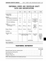
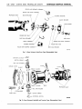
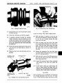
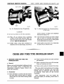
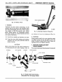
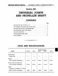
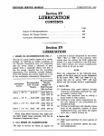
Section XII
UNIVERSAL JOINTS AND
PROPELLER SHAFT
SERVICE BULLETIN REFERENCE
NUMBER
DATE
SUBJECT
CHANGES
CHRYSLER SERVICE MANUAL
UNIV JOINTS AND PROPELLER SHAFT—537
UNIVERSAL JOINTS AND PROPELLER SHAFT
DATA AND SPECIFICATIONS
C-67
C-68
C-69
C-70
C-300
Propeller Shaft
Number used
Diameter
With Standard Transmission.
31/2 in.
With PowerFlite Transmission
3 in.
3 in.
31/2 in.
With Air Conditioning
3 in.
31/2 in.
31/2 in.
Length
Centerline to Centerline
of "U" Joints
59% in.
61 25 / 32 in.
Flange to Flange
Front and Rear
2V2 in.
Front and Rear
2V2 in.
58i/8 in.
6iy 2 in.
31/2 in.
3V2 in.
(Front)
52% in.
(Rear)
29n/ 16 in.
60%2 in.
6iy 2 in.
*Pre-Pack
Lubrication . . . .
Universal Joints
Type
(Front) Ball and Trunnion Type
(Rear) Cross Type
Bearing Type
Cross Type
(Only)
(Front)
Ball and
Trunnion
(Rear)
Cross
Type
Anti-Friction
'Every 20,000 miles
TIGHTENING REFERENCE
Foot-Pounds
Ball and Trunnion Type Joint Attaching Bolts
55
Cross Type Joint Attaching Bolts
20
Spline Oil Seal Cap
25
Companion Flange Nut
NOTE: These specifications are for standard axle ratios.
150
538—UNIV JOINTS AND PROPELLER SHAFT
CHRYSLER SERVICE MANUAL
ROLLER AND BUSHING ASSEMBLY
ROLLER AND BLOCK ASSEMBLY
PROPELLER SHAFT
BLOCK RETAINER
BUSHfNG RETAINER
BLOCK RETAINER
LOCKWASHER
ROLLER DUST SEAL
DUST SEAL RETAINER
SHAFT BOLT
CROSS ASSEMBLY
ROLLER AND BLOCK ASSEMBLY
BUSHING RETAINER
ROLLER DUST SEAL
ROLLER AND BUSHING ASSEMBLY
DUST SEAL RETAINER
55x767
Fig.
1—Rear Universal Joint-Cross Type (Disassembled View)
CENTERING BUTTON - »" BUTTON SPRING
BALL A N D ROLLERS
GREASE COVER
THRUST WASHER
BODY
PROPELLER SHAFT
BALL A N D ROLLERS
LOCKWASHER
SHAFT BOLT
BUTTON SPRING
CENTERING BUTTON
54x49
Fig. 2—Front Universal Joint-Ball and Trunnion Type (Disassembled View)
CHRYSLER SERVICE MANUAL
UNIV. JOINTS AND PROPELLER SHAFT—539
Section XII
UNIVERSAL JOINTS AND
PROPELLER SHAFT
UNIVERSAL JOINTS
Two types of Universal Joints are used on the
1955 Chrysler Models and are as follows: The
Cross Type, as shown in Figure 1, and the Ball
and Trunnion Type, as shown in Figure 2.
The ball head of each joint of the Ball and
Trunnion Type, is an integral part of the tubular
propeller shaft and is covered by the joint body.
The pin, with the balls, needle bearings, thrust
washer, centering button, and button spring at
each end, extends through the propeller shaft
ball and rides in the ball channels in the body of
the joint assembly. This balanced installation is
designed to absorb the thrust and torque of the
drive line. This type of joint is used in Models
C-67, C-68, C-69 and C-300 at the front universal
joint.
The Cross Type universal joint is used at the
rear joint of all models, and the front and center
bearing joints of the C-70 Models. The C-70
Models are equipped with a center bearing and
two propeller shafts.
No adjustments are provided to compensate
for wear in the universal joint assembly. Parts
that show excessive wear must be replaced.
CAUTION
When disassembling universal joints, keep parts
identified as to original position. Failure to
assemble parts in their original positions may
cause an unbalanced condition in the propeller
shaft.
CROSS TYPE
1. SERVICING CROSS TYPE UNIVERSAL
JOINTS (Fig. 1)
(1) Disconnect front end of propeller shaft at
transmission flange.
(2) Disconnect rear end of propeller shaft and
remove propeller shaft.
(3) Remove two bushing retainers and remove
bushings. Tilt the cross so that it may be
removed from the propeller shaft yoke.
(4) Straighten out the end of the retainer lock
and remove the two roller and block assemblies.
(5) Remove the dust seals and retainers.
(6) Inspect parts and replace parts that show
wear.
(7) Lubricate the roller and bushings with universal joint grease (extreme pressure) and
assemble joint in reverse order of disassembly.
540—UNIV. JOINTS AND PROPELLER SHAFT
CHRYSLER SERVICE MANUAL
BALL AND TRUNNION TYPE
2. SERVICING BALL AND TRUNNION TYPE
UNIVERSAL JOINTS
To disassemble universal joint for repair or inspection of all component parts, refer to Figure 2
and proceed as follows:
(1) Remove the joint body metal cover and gasket by bending tabs of cover away from the
body; then remove cover and gasket.
(2) Slide body down on propeller shaft exposing
the two centering buttons. Remove the centering buttons and springs from the ends of
the trunnion pin.
(3) Slide the two balls, rollers, and thrust washers off the trunnion pin.
(4) Wash all parts with cleaning solvent and
blow dry with compressed air. Inspect and
replace worn parts.
NOTE
Reconditioning of ball and trunnion type universal joints will only be necessary when excessive
free backlash exists between the balls and the
trunnion. In some instances, it will be found that
the universal joint body has worn, and it will be
necessary to replace all parts, including the body
pin, thrust washers, and centering buttons.
Worn rollers should also be replaced.
3. UNIVERSAL JOINT MAINTENANCE
(BALL AND TRUNNION)
The universal joints, propeller shaft, and hand
brake drum are accurately balanced during the
process of manufacture. Care should be exercised
to maintain this condition of balance by close
adherence to the following:
(1) Do not use more than 2% ounces of lubricant in a universal joint (ball and trunnion
type) at any time.
(2) Keep the propeller shaft, hand brake drum,
flanges, etc. free from undercoating, dirt,
and ice.
CAUTION
When installing trunnion pin in propeller shaft
care should be taken to see that the trunnion pin
is centered in the shaft. Each end of pin should
protrude the same distance, with a variation of
no more than .003 inch. If one side of the pin extends more than .003 inch farther than the other,
the propeller shaft will be out of balance. Tool
C-552, as shown in Figure 3, will facilitate the
removal, installation, and centering of the trunnion pin.
(3) Failure to observe these recommendations
may result in an out-of-balance condition
causing vibration.
4. SERVICING EXTERNAL TYPE UNIVERSAL
JOINT DUST COVER
Fig. 3—Installing Universal Joint Pin
To replace an external type universal joint dust
cover (Fig. 4) that is damaged, remove the propeller shaft assembly from the car and clamp
lightly in a vise. One end of the shaft should be
resting on the bench in a horizontal position, then
proceed as follows:
CHRYSLER SERVICE MANUAL
UNIV. JOINTS AND PROPELLER SHAFT—541
55x766
Fig. 4—External Type Dust Cover
Fig. 6—Working Dust Cover Through Body
(1) Disassemble joint, removing all parts except
the body and pin.
(2) Clean body, ball head, and pin thoroughly.
(3) A complete coating of grease (or suitable
rubber lubricant) must be smeared on the
outside and inside of dust cover, entire surface of the ball head, pin, and inside of body.
(It is very important that this instruction
be followed.)
(4) Stretch the grease-soaked boot or dust cover
over the pin and ball head as shown in
Figure 5.
(5) Work the dust cover into the body as far as
possible.
UNIVERSAL JOINT
CENTERING PIN
PROPELLER SHAFT
CAUTION
USE NO TOOLS FOR THIS OPERATION.
(6) With the body in position so the pin can
enter the ball channels, pull the body sharply over the pin, thereby forcing the dust
cover into the body.
(7) With one hand, grip the end of the dust
cover, protruding through the back end of
body. With the other hand, pump the body
back and forth, as shown in Figure 6, until
the entire dust cover has passed through
the body.
(8) During the operation the cone may have
reversed itself inside the dust cover. Pull it
out to its normal position.
(9) Slide, the dust cover in the ball head groove
and over the neck of the body, then secure
with clamps provided.
(10) Insert 21/2 ounces of heavy fiber, universal
joint grease in the joint and install the
cover.
(11) Install shaft, using new lockwashers. Be
sure to double check the flange bolts for
tightness, to insure against grease leakage.
Recheck after 1,000 miles of operation.
UNIVERSAL JOINT
DUST COVER OR
BOOT
UNIVERSAL JOINT BODY
49x910
Fig. 5—Sliding Cover over Ball Head and Pin
CAUTION
Never attempt to use a needle-like arrangement
for forcing lubricant into the boot (or dust
cover) on the universal joints. Excessive grease
542—UNIV. JOINTS AND PROPELLER SHAFT
CHRYSLER SERVICE MANUAL
CLAMP GROOVE
(LARGE)
JOINT BODY
BALLHEAD
55x771
Fig. 7—internal Type Dust Cover
DUST COVER'
can be forced into the boot and cause the shaft
to be thrown out of balance, burst boot, or the
lubricant can be lost through the injection hole
during high speed operation. The joints must be
disassembled and packed with universal joint
grease.
5. SERVICING INTERNAL TYPE UNIVERSAL
JOINT DUST COVER
The propeller shafts incorporating the internal
type dust covers (Fig. 7) are standard on the
C-300 Models, and New Yorker Models equipped
with air conditioning.
To replace a damaged dust cover proceed as
follows:
(1) Remove propeller shaft from car, and lightBODY
v—-•
55x772
Fig. 9—Installing Small Clamp on Dust Cover
ly clamp shaft in a vise, with the other end
supported in a horizontal position.
(2) Disassemble joint; remove all parts except
the body and pin.
(3) Clean all parts including body, ball head, and
pin thoroughly.
(4) Push body all the way back, install boot by
stretching it over the ball head and pin, as
shown in Figure 8. No lubricant applied to
any parts thus far.
(5) Position boot as near to ball head as possible,
then form small clamp around boot and
thread one end of clamp through slot provided in other end of clamp.
(6) Use suitable pliers to constrict clamp as far
as possible by hand (Fig. 9). Secure clamp
by bending end of clamp completely over.
Do not cut off excess amount of clamp.
(7) Apply light coat of universal joint grease to
inside of body. This will aid in working boot
through body.
BALLHEAD
(8) Install thrust washers, balls, rollers, etc. on
ends of pin.
DUST COVER
PIN
55x768
Fig. 8—Sliding Dust Cover over Ball Head and Pin
(9) Pull body over ball head and work back and
forth until boot protrudes enough to be
grasped with fingers; then pull boot through
body, as shown in Figure 10.
CHRYSLER SERVICE MANUAL
UNIV. JOINTS AND PROPELLER SHAFT—543
DUST COVER
BODY
55x770
55x769
Fig. 10—Working Dust Cover Through Body
Fig. 11—Cleaning Lubricant from Contacting Surface
of Dust Cover
CAUTION
Do not use any sharp tool for this operation.
cessive amount of clamp and completely
bend end of clamp over.
(10) Wipe off any lubricant from contacting
surfaces on both body and boot (Fig. 11).
Clean the clamp groove also on the outside
of boot. THIS IS IMPORTANT.
(12) Coat ball head assembly and inside of body
with 2 ounces of universal joint grease.
Work body back and forth so that grease
will be distributed on all parts.
(11) Install clamp, using same procedure as
described for the small clamp. Cut off ex-
(13) Install gasket and grease cover. Bend tabs
of cover over to secure cover.
CROSS AND YOKE TYPE PROPELLER SHAFT
6. SERVICING CROSS AND YOKE TYPE
PROPELLER SHAFT
a. Removal
Remove nuts and lockwashers holding universal
joint and propeller shaft to differential and
transmission companion flanges. Remove propeller shaft assembly.
b. Disassembly
(1) Place assembly in a bench vise and remove
the cross roller bearing block tie retainer
which holds the cross roller bearing blocks
on cross.
(2) Remove bearing blocks, dust seals, and dust
seal retainers.
(3) Remove retainers from cross roller bearings.
Press out bearings and cross.
(4) Remove dust seals and retainers from cross.
The cross roller bearing block and its component parts form an assembly. The cross roller
bearing, with its component parts, also form
an assembly. These parts are not serviced
separately.
After disassembly, clean and inspect the
parts and replace, as necessary, those worn or
damaged.
544—UNIV. JOINTS AND PROPELLER SHAFT
CHRYSLER SERVICE MANUAL
Fig. 12—Balance Arrows
c. Assembly
Lubricate all parts before assembling. If the
splined joint at the front of the propeller shaft
has been disassembled, fill cavity with 5 ounces
(by weight) of MS 870 pressure gun, winter
grade, chassis grease. On 8-passenger models,
the center bearing is a sealed bearing and does
not require lubrication.
51x854
Fig. 14—Removing Companion Flange Nut
sure balance arrows are in alignment (Fig. 12).
(1) Install dust shields and retainers on cross.
Place propeller shaft in its correct position under
car. Make certain that the slip-spline end of the
shaft is located toward front of car. Insert attaching screws and tighten securely.
(2) Press the cross roller bearing and bushing
assembly into the yoke with the cross in
proper location.
CAUTION
Make certain that all of the roller bearings are
correctly placed in the roller bushing. Also, be
COTTERPIN
DUST SLINGER
HOUSING
7. SERVICING PROPELLER SHAFT
CENTER BEARING
The center bearing and housing must be removed
CENTER BEARING
NUT
WASHER
FLANGE
LOCKWASHER
NUT
Fig. 13—Propeller Shaft Center Bearing—
Disassembled View (8 Passenger Models)
CHRYSLER SERVICE MANUAL
UNIV. JOINTS AND PROPELLER SHAFT—545
FRONT PROPELLER SHAFT
FRONT PROPELLER SHAFT
51x857
Fig. 17—installing Companion Flange
51x855
Fig. 15—Removing Companion Flange
FRONT
PROPELLER
SHAFT
quired. (Refer to Fig. 13.) The service procedure
is as follows:
(1) Clamp front propeller shaft in a vise and
remove cotter pin. Place Tool C-784 over
flange (Fig. 14) and remove flange nut and
flat washer.
(2) Index and mark flange and shaft (to retain
original balance). Remove flange and slinger
from shaft with Tool C-452, as shown in
Figure 15.
(3) With the jaws of Tool C-459 over the housing, as shown in Figure 16 (be careful not to
crimp slingers), force slingers and bearing
off the shaft.
51x856
Fig. 16—Removing Center Bearing from Shaft
(4) Remove bearing from housing with a suitable drift.
as a unit, together with the front propeller shaft,
for servicing.
When installing new bearing, use drift, Tool
C-202, being careful to start bearing evenly to
avoid distorting bushing.
The splined center flange is fastened to the end
of the propeller shaft and holds the slingers and
center bearing securely on the shaft. The center
bearing, housing, and slingers, can be disassembled, inspected, and parts can be replaced as re-
Insert splined end of shaft with slinger
through bearing and slide center bearing flange
over shaft. Draw flange on shaft with Tool C-496,
as shown in Figure 17. Tighten nut to 150 footpounds torque.
546—UNIV. JOINTS AND PROPELLER SHAFT
CHRYSLER SERVICE MANUAL
SERVICE DIAGNOSIS
8. PROPELLER SHAFT VIBRATES
Possible Causes:
a. Undercoating on shaft, flanges, drums, etc.
b. Loose companion flange nuts.
c. Improper alignment of balance arrows.
d. Flange runout.
it is possible to correct a flange runout condition
by repositioning the universal joint 180 degrees
with the companion flange. Reposition only one
universal joint at a time and road test car after
each repositioning operation.
e. Check the splines. If excessively loose, inspect the splines on the shaft or in the flange foi
wear or damage. Replace shaft of flange, as necessary, to correct this condition.
e. Worn spines on shaft or in flange.
Remedies:
a. If propeller shaft, drum, and flange are not
shielded while car is being undercoated, the
undercoating material may accumulate on the
underside of the propeller shaft and cause vibration. To remedy such a condition, inspect shaft
and remove the undercoating material (if present) with a suitable solvent.
b. Check transmission flange nuts and rear
axle differential flange nuts for looseness. Tighten to Data and Specifications.
c. Check alignment of balance arrows on both
shaft and front universal joint. These arrows
must be exactly in line. If not, reposition splines
so that arrows are properly aligned.
d. Check for flange runout. In many instances,
9. UNIVERSAL JOINTS NOISY
Possible Causes:
a. Loose propeller shaft flange bolts.
b. Improper lubrication.
c. Worn universal joint bearings.
Remedies:
a. Check universal joints for possible damage
and tighten propeller shaft flange bolts to Data
and Specifications.
b. Disassemble universal joints and inspect
all parts for wear or damage. Replace parts as
required, pack bearings with universal joint
grease and reassemble.
c. Inspect universal joint bearings for wear
and replace as necessary.