1
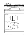
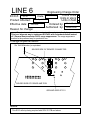
AxSys 212 Service Manual
Version 1.1
June 5th, 1997
©1996, 1997 Fast Forward Designs, Inc.
This service manual contains confidential proprietary information.
This manual may not be copied in whole or in part without
written authorization of Fast Forward Designs, Inc.
Table of Contents
Overview ......................................................................................................
3
Checking the software version
3
......................................................................
Re-initializing the edit buffer and global parameters
Re-initializing all user programs
Disassembling the Head
Changing the software
.....................................
....................................................................
3
3
...............................................................................
4
..................................................................................
4
Changing the Power Amps
...........................................................................
5
Changing the Transformer
...........................................................................
6
................................................................................
7
Description of Circuitry
Power Supply................................................................................................................................................ 7
Audio Input ................................................................................................................................................... 9
DSP ................................................................................................................................................................... 9
Audio Output ............................................................................................................................................... 9
Microcontroller ......................................................................................................................................... 10
User Interface ............................................................................................................................................ 10
Reset Circuit............................................................................................................................................... 10
Accessing the test routines
Descriptions of Test Routines
..........................................................................
11
......................................................................
11
Troubleshooting
..........................................................................................
14
Software history
..........................................................................................
14
Revision history and ECOs
Schematics
...........................................................................
15
..................................................................................................
36
Parts list ......................................................................................................
40
Line 6 AxSys 212 Service Manual ..........................................................Page 2
Overview
The AxSys 212 is a stereo guitar amplifier that processes the guitar signal digitally. This
makes many aspects of it quite different than other tube or solid state guitar amplifiers.
All of the controls that affect the guitar sound are implemented in the software that is
loaded into the digital signal processors. In order to become more familiar with how the
AxSys 212 operates and the specifics of its features, we recommend reading the owner’s
manual prior to performing any service functions.
The two main components of the AxSys 212 are the wood box (with two 12" speakers)
and the head (enclosed in an aluminum box). All of the electronics of the AxSys 212 are
contained in the head.
Checking the software version
To check the software version of the AxSys 212 without opening the head, press and hold
the button next to the edit row labeled AUX/MIDI and the button next to the edit row
labeled MAIN at the same time. The display will show the software version number.
Re-initializing the edit buffer and global parameters
Press and hold TUNER and COMPARE at the same time while turning the power on.
Wait until the display reads “Edt” (edit) and then “CLr” (clear) to indicate that the edit
buffer has been cleared. In addition to the edit buffer being cleared, all of the global
parameters (global Aux settings, global noise gate settings, MIDI channel, and global
Main controls) will be set to their default values. For more information on global
parameters, please refer to the owner’s manual.
Re-initializing all user programs
Press and hold USER/PRESET and STORE SOUND at the same time while turning the
power on. Wait until the display reads “PrE” (presets) and then “Str” (stored) to indicate
that the all 128 Presets have been stored into the 128 User sound locations.
WARNING: This procedure will erase ALL user program memory. Be sure that
any user sounds that are desired to be retained are saved to another AxSys 212 or to
a MIDI sysex storage device first. See the owner’s manual for more information on
storing sounds via MIDI.
Line 6 AxSys 212 Service Manual ..........................................................Page 3
Disassembling the Head
Before proceeding, be sure the power is off and the AC cable is disconnected. You will
also need to disconnect the two 1/4” speaker plugs from the rear panel.
First locate two Phillips screws on each side panel of the amp cabinet (four screws total).
These screws keep the amp head from moving side to side. Take out all four, making
sure not to lose the finishing washers.
Next, take out the two screws that hold the top handle. They provide the main support
for the head (on newer units you will see two additional screws on the top that also need
to be removed). As you remove them, try to support the descending weight by lifting up
on the head from behind.
Carefully slide the chassis straight out from the back of the cabinet, being very careful
not to tear the vinyl covering. You’ll need to use two hands in order to ease both sides
out evenly.
Now that you have the amp head out, remove the eight screws that hold the bottom plate
on the chassis. Some amps also have an additional support bracket (mentioned in ECO
#3) that will also be removed when taking out these screws. Newer amps will have nine
screws instead of eight, and will not have the support bracket.
Changing the software
Caution: When changing software, there is always the possibility that the user program
memory could be erased due to electrostatic discharge. It is always a good idea to save
the user programs to a MIDI storage device before changing the software or performing
any work on the Processor board.
After disassembling the head, locate the EPROM at U14 on the Processor PCB (it is the
only socketed chip, and will have a sticker on it indicating the version number). Notice
which end of the EPROM has a notch; the EPROM socket has the same indented notch.
You’ll want the new chip to be oriented the same direction. Always double check to
make sure the chip you’re installing faces the same way as the socket. Carefully pry out
the old chip with an EPROM puller or a flat screwdriver.
Insert the new chip in the socket; again remember to match the notched ends. Check to
make sure all the chip legs are aligned with their female counterparts in the socket. Press
the chip firmly in place from directly overhead.
Now you can reassemble the amp by following the disassembly instructions in reverse.
Plug the power cord in and then turn the amp head on while holding the Compare and
Tuner buttons. This will reinitialize all of the global settings and the current edit buffer,
but will not affect the user programs. If you want to erase and reinitialize all of the User
programs as well, hold Preset/User and Store together while powering on (please read
“Re-initializing all user programs” above first).
Line 6 AxSys 212 Service Manual ..........................................................Page 4
Changing the Power Amps
Note: On units prior to serial number A1-007719, the possibility of one or both power
amps failing due to an over voltage on the AC input is slightly higher than normal. This
is due to the slightly higher secondary voltage of the original transformer design, #4-498604 (Line 6 part number 11-30-0010). If a power amplifier needs to be replaced on a
unit prior to A1-007719, it is recommended that the transformer also be replaced (see
next section).
Follow the procedure in the section “Disassembling the Head” above. Remove the rear
PC board by removing the screws holding the power amp devices, and the nuts holding
the 1/4” jacks.
Before unsoldering the power amplifiers (located at U1 and U2), note the horizontal
spacing between the pins and the circuit board. When the new power amplifiers are
installed, provide the same spacing. Remove power amplifiers from the circuit board.
Using wire cutters, cut the pins on the power amplifier so the body can be removed.
Remove the remaining pieces of the power amplifier pins from the circuit board.
Install new National LM3886TF power amplifiers, allowing some space between the pins
and the circuit board. This reduces the possibility of shorts between power amplifier pins
and the pads on the circuit board.
If the serial number is prior to A1-008646, add a jumper on each power amplifier
between pins 1 and 5 (as further described in ECO #8). The jumper should be soldered
on the bottom side of the circuit board. Use 26 gauge or larger wire. See bottom of
board diagram below:
10
11
8
9
6
7
4
5
2
3
1
Jumper
Place circuit board back into chassis, being sure to apply thermal grease between the
power amplifiers and the rear metal panel. Replace black hex nuts and power amplifier
mounting screws.
Line 6 AxSys 212 Service Manual ..........................................................Page 5
Changing the Transformer
On units prior to serial number A1-007719, a dual primary transformer with a slightly
higher secondary voltage was used. If power amplifier failure occurs, the transformer
should be replaced with transformer number 4-49-8607 (part # 11-30-8607) for
100/120VAC, or transformer number 4-49-8609 (part # 11-30-8609) for 220/240VAC.
First, disconnect all colored wires from the transformer. Remove the four screws holding
the transformer in place and remove the transformer. Place re-enforced bracket (part
#30-21-0012) on top of chassis where transformer sits. Place the gasket (part #30-402825) on top of re-enforced bracket. Place the new transformer on top of gasket. See
diagram below.
TRANSFORMER
ADDED GASKET
(Line 6 Part # 30-40-2825)
RE-ENFORCEMENT BRACKET
Insert screws with lock washers and tighten. Reconnect colored wires to transformer as
described in section (Description of Circuitry, Power supply). The black and gray wires
should be removed.
Line 6 AxSys 212 Service Manual ..........................................................Page 6
Description of Circuitry
Inside the head are two main printed circuit boards (PCBs) connected together with a 20
pin ribbon connector: the Processor board (including the small breakaway board for the
input jacks) and the Power board (including the small breakaway board for the AC input).
The Processor board contains all of the digital electronics, including the microcontroller,
memory, software EPROM, DSPs,(Digital Signal Processors) etc., and the ADC (Analog
to Digital Converter) and DAC (Digital to Analog Converter). It also contains all of the
front panel controls (buttons, LEDs, and potentiometers).
The Power board contains the power supply, and the two audio power amplifiers that
power the speakers. It also contains all of the input and output connectors on the rear
panel.
Power Supply
The power supply section is located on the Power board. 100V-120VAC or 220V240VAC is applied at IEC connector J9. SW1 is the power switch located on the rear
panel. L1, L2, and C20 are used to filter RFI from the AC line. The power passes
through fuse F1. The AC is then connected to the power transformer through four wires.
For older units (serial numbers A1-005001 through A1-007718, which used transformer
part number 4-49-8604, our part number 11-30-0010), the position of these wires on the
PCB at pad locations H1 through H6 determine whether the AxSys 212 is wired to
receive 120VAC or 240VAC. The color of the wires connected to the transformer should
correspond to the colors labeled on the PCB for the appropriate line voltage, as follows:
PCB Pad
H1
H2
H3
H4
H5
H6
120VAC
Gray
White
no connect
no connect
Brown
Black
240VAC
no connect
White
Gray
Black
Brown
no connect
Units with serial number A1-00719 and above use one of two different transformers
depending on the input voltage. For 100-120V AC, transformer number 4-49-8607 (our
part number 11-30-8607) is used. For 220-240V AC, transformer number 4-49-8609 (our
part number 11-30-8609) is used. In both cases, the black and gray wires described
above are no longer necessary. The wiring at the PCB pads H1-H6 should be as follows:
PCB Pad
H1
H2
H3
H4
H5
H6
Any AC
no connect
White
no connect
no connect
Brown
no connect
When replacing an older transformer with a newer one, the black and gray wires should
be removed.
Line 6 AxSys 212 Service Manual ..........................................................Page 7
If the wires become disconnected from the transformer, they should be connected as
follows:
Transformer 4-49-8604 (Line 6 #11-30-0010) 120V/240V
REAR PANEL
BROWN
BLUE
WHITE
RED
YELLOW
BLACK
GREEN
GRAY
ORANGE
4-49-8607 (Line 6 #11-30-8607) 100V
4-49-8609 (Line 6 #11-30-8609) 220V
CHASSIS
CHASSIS
BROWN
BLUE
RED
YELLOW
GREEN
ORANGE
WHITE
4-49-8607 (Line 6 #11-30-8607) 120V
BROWN
WHITE
YELLOW
GREEN
ORANGE
WHITE
4-49-8609 (Line 6 #11-30-8609) 240V
CHASSIS
BROWN
BLUE
RED
CHASSIS
BLUE
RED
YELLOW
GREEN
ORANGE
BROWN
WHITE
BLUE
RED
YELLOW
GREEN
ORANGE
In all cases, there are two secondary windings on the transformer, one with a center tap.
The center tapped winding (connected through H7, H8, and H9) is connected to a full
wave bridge rectifier D1, which generates the +35VDC and -35VDC used to power the
power amplifiers, and are filtered via C15 and C16. These voltages will actually measure
to be about ±44 volts when no audio is being played at the speakers. The other secondary
winding (connected at H10 and H11) is half rectified through D2 and filtered by C17 to
Line 6 AxSys 212 Service Manual ..........................................................Page 8
generate approximately +8VDC, and half rectified through D3 and filtered by C18 to
generate approximately -8VDC. The +8VDC voltage is connected to regulator U3 to
generate the +5VDC (and filtered by C19), which is used by most of the circuitry on the
main board.
Audio Input
The aux input signal and guitar input signal enter through J1 and J2, respectively, on the
small break away PCB adjacent to the Processor Board. The signals are filtered for radio
frequencies via C1 and C3, AC coupled by C2 and C4, have a 1 megohm load via R1
and R3, pass through R2 and R4, and are then voltage limited by zener diodes D12/D13
and D14/D15. The signals are then buffered through U1A and U1B, which are two
opamps of a TL084 quad opamp. The input level of the aux and guitar inputs are
controlled by R6 and R8, respectively, which control the gain of U1C and U1D. The
signals then pass through R9 and R10/C59 into the two inputs of U2, which is a 20-bit
ADC modulator. The modulator outputs are connected to U3 which digitally filters the
modulator output and generates the digital audio signals for the DSP though pin 18 in a
serial 20-bit, 31.2KHz sample rate format. This serial data is clocked by the BIT_CLK
(1.9968MHz) and LR_CLK (31.2KHz) signals, both of which are generated by the ADC
digital filter U3 by dividing the signal labeled 12MHz (which is actually 11.9808MHz)
by 6 and 384, respectively.
DSP
Located on the Processor board, the DSP section consists of two 24-bit, 24 MIPS
(Million Instructions Per Second) DSP chips (U12 and U19), one 64K by 16 bit DRAM
(U13), and a counter and shift register (U20 and U21, respectively) for loading the DSP
instructions. The serial digital audio input is connected to the serial inputs of both DSPs
at pin 78 (ADC_DATA), and clocked in via the BIT_CLK and LR_CLK signals
generated by U3. The DSP software to be executed and the coefficients required by the
DSP are serially downloaded to U12 and U19 from the microprocessor (U9). This is
accomplished by the micro loading the specific data into shift register U21, which
triggers U20 to shift the 8 bits of data into the selected DSP in about 1.3 microseconds.
When the user changes sounds, the micro will download a large amount of data
(depending on how different the sound is from the previous sound) to the DSPs. Much of
the DSP process (compression, EQ, tube modeling, tremolo, etc.) is handled entirely
inside the DSP chips using internal RAM. Some of the processing, notably the
chorus/flange, delay, and reverb, require much larger amounts of RAM than is available
inside the DSPs. This processing is handled by the DSP at U19, and it utilizes the
DRAM at U13 for these functions. U13 also outputs the final digital outputs
(DAC_DATA) serially at U49 for the DACs.
Audio Output
The DSP's digital output is connected to the DAC U4. This signal contains both the left
and right data. The DAC is clocked by the BIT_CLK and LR_CLK signals generated by
ADC U3. The DAC converts the signal into 2.8 volt peak-to-peak (maximum) analog
voltages centered at 2.5 volts, and outputs them at pins 17 and 18 for the right and left
output, respectively. These signals are AC coupled through C32 and C33 and then
passed through the stereo volume potentiometer, R71. Additional gain is then provided
by U5 (5532 dual opamp) before passing the signals through the ribbon cable to the
Power board. The signals are then passed through U1 and U2, which are the 50W power
Line 6 AxSys 212 Service Manual ..........................................................Page 9
amplifiers. The outputs of U1 and U2 are connected to the speaker output jacks J1 and
J2, as well as resistors R13 and R14 for driving the headphone output jack.
Microcontroller
Located on the Processor board, the Microcontroller section consists of the 80C31
microcontroller (U9), and address latch (U11), a 64K by 8 bit EPROM for the software
(U14), and a 32K by 8 bit SRAM (U15) for scratch pad memory and user sounds. The
microcontroller is clocked by a 11.9808MHz crystal, which (through U10) is also used to
clock the DSPs, the ADC, and the DAC. The micro fetches operating instructions, DSP
code, and preset sounds from the EPROM. It downloads the DSP code as described in
the DSP section. The micro's serial ports are connected through the ribbon connector to
the Power board, where they are used for the MIDI input and output (J3 and J4,
respectively). The MIDI input first passes through optoisolator U4. The micro also
interfaces to the LEDs, switches, and pots as described in the next section. The decoding
of the latches used for the switches and LEDs is controlled by address decoder U18.
User Interface
On the Processor board, the front panel circuitry consists of all of the components
relating to the switches, LEDs, and edit potentiometers. For the switches, the
microcontroller selects one column of the switch matrix at a time by loading the latch U8
appropriately, and then reads the data at its input port 1 bits 5 through 7 (which have
internal pull-up resistors). The micro then selects the next column, until all switches have
been checked. The LEDs are also arranged as a matrix, and are multiplexed by the
microprocessor. U18 is used to connect one column of LEDs to ground at a time, and
U17 is used to latch that column's LEDs on or off. The micro varies the amount of time
an LED is turned on in order to control the brightness of the LEDs next to the six edit
pots. The signal labeled LED connected to R67 and C49 is used by the micro to change
the amount of current driving the LEDs to further control the level of the variable
brightness LEDs. The six edit potentiometers are connected to an 11 input, 8-bit ADC
(U7). The micro can read the 8-bit digital values of the pots serially by selecting this chip
and clocking out its data. The remaining inputs of U17 are used for the two variable
pedal inputs, the remote footswitches, sensing A/D clipping, and for sensing whether or
not anything is plugged into either of the pedal inputs or the headphone output. The two
pedal inputs are designed to work with 9K ohm linear potentiometers.
Reset Circuit
On the Processor board, zener diode D57 is used to monitor the +8VDC supply voltage
(which is used by U3 on the Power board to generate +5VDC). If this voltage drops
below 7 volts, transistor Q3 will turn off, causing transistor Q4 to turn on, which will
cause inverter U10D to reset the microcontroller. This signal is inverted again at U10E
and is used to reset the ADC digital filter U3 and LED latch U16. The DAC and the
DSPs are reset by the microcontroller software via the signal PRESN, which will be low
upon power up since the micro's port outputs are set high when the micro is reset.
Line 6 AxSys 212 Service Manual ........................................................ Page 10
Accessing the test routines
Press and hold the STORE SOUND button while turning power on until the display reads
“SrA” to access the internal test routines. Different tests can be selected by using the
BANK UP or BANK DOWN buttons. The selected test is started by pressing the
TUNER button. The display will then usually show “Err” (error) or “PAS” (pass) to
indicate the test status. The nine tests are:
# Display
1. SrA
2. EPr
3. LEd
4. bAt
5. bUt
6. PEd
7. AC
8. idi
9. Aud
10. AdA
Name
SRAM test
EPROM test
LED test
Battery test
Button test
Pedal test
AC timer test
MIDI test
Audio test
A/D/A path test
Description
Tests SRAM (U15)
Tests EPROM (U14)
Lights all LEDs
Tests SRAM retention
Tests buttons & pots
[only at factory]
Tests AC freq counter
Tests MIDI in & out
Passes audio with delay
Tests audio THD, etc.
Result Display
Err or PAS
Err or PAS
no result; visual inspection
Err or PAS
Displays button or pot name
Err
Err or PAS
Err or PAS
Err or blank
Err or PAS (version 1.05)
Power off then on to exit the test routines.
Descriptions of Test Routines
SrA The SRAM test performs read and write cycles to all memory locations of the
SRAM. If the data read back is different than what was written, the display will show
Err. If this occurs, check all signals connected to U15.
EPr The EPROM test calculates the checksum of the EPROM and compares it with
the checksum stored in the EPROM. If it does not match, the display will show Err. If
this occurs, it usually indicates that there is some erroneous data in the EPROM (or a
missing checksum), and the EPROM should be replaced (U14). It could also be caused
by a problem on an upper address line connected to the EPROM. However, in general,
major problems with the EPROM or the address and data lines are likely to prevent any
of the test routines to be entered in the first place.
LEd The LED test can be used to check that all LEDs are functioning properly. First,
all LEDs will turn on at the same time. Then, the software will cycle each LED on and
off one at a time. When the six LEDs next to the edit potentiometers are cycled, they will
be lit at half brightness. NOTE: When entering this test, holding TUNER will cause all
of the LEDs to stay on until the button is released.
bAt The battery test actually is testing the SRAM’s contents, which can be an
indicator as to the battery status. It checks to see if a specific set of SRAM locations
contain specific data. This data is loaded in once at the factory, and it is assumed that if
the data remains unchanged in the field, the battery is working properly. If an error
occurs, it will be necessary to check the battery, the SRAM, and the reset circuitry. Once
an error has occurred, it will continue to reoccur until the specific data is written back to
the SRAM. This can be performed from within this test routine by pressing and holding
Line 6 AxSys 212 Service Manual ........................................................ Page 11
the SOUND D button and the USER/PRESET button. The display will show “---” to
indicate that the SRAM has been initialized.
bUt The button test can be used to check that each button and edit potentiometer is
working properly. Pressing each button will cause the name of that button to be
displayed. The display will show as follows:
Button
no button
User/Preset
Sound Bank Up
Sound Bank Down
Sound A
Sound B
Sound C
Sound D
Tuner
Compare
Store Sound
Function 1
Function 2
Function 3
Function 4
Function 5
Function 6
Display
“---”
“U-P”
“UP ”
“Dn “
“A“
“b“
“C“
“d“
“tnr”
“CPr”
“Str”
“Fn1”
“Fn2”
“Fn3”
“Fn4”
“Fn5”
“Fn6”
The function buttons are the small black buttons to the left of the edit matrix. The top
button is 1 and bottom button is 6. When any of the six edit potentiometers are turned,
the display should read “P1” through “P6”, depending on which pot was turned. This test
can be exited by pressing the function 5 and function 6 buttons at the same time. This is
indicated by the LEDs next to each of these switches being lit.
PEd The sixth test is performed on a test fixture at the factory to verify that the pedal
inputs are working. Without the test fixture, this test will always result in an “Err”. For
this reason, this test should always be skipped. The pedal inputs can be easily tested by
performing a functional test to see that the wah and volume functions are being controlled
by the pedals. If the pedal inputs do not work, try checking that the voltages reach the
ADC (U7), and that the switch in each jack is working properly. This switch lets the
micro know that something is plugged in, and is sensed by checking the ADC voltage at
U7 pin 11 and comparing it to the table shown in the Power PCB schematic.
AC
The AC verifies that the micro can properly determine the current AC line
frequency. It expects to find 50Hz or 60Hz, and will display an “Err” if the results are
different. If this occurs, check the Power PCB signal labeled AC, as well as R38 and Q1
on the Processor board.
idi
The MIDI requires that a MIDI cable be connected from the MIDI output back to
the MIDI input. Without this cable, this test will always fail. If the test fails with the
cable, check the connection first, then check U4 on the Power board, and then check for
the serial interface signals at the microcontroller U9 pins 11 and 13 and follow the signal
path through to the MIDI connectors.
AUd The Audio takes the Guitar input and passes it unmodified to the left speaker, and
takes the Aux input and passes it unmodified to the right speaker. It also adds a 1 second
Line 6 AxSys 212 Service Manual ........................................................ Page 12
delayed signal to each of these signals in order to verify that the audio DRAM (U13) is
functioning properly. The audio passes through both DSPs, so this test checks their
functionality as well. The display should be blank during this test. If the display reads
“rd1 or “rd2” followed by “Err”, this means that an error occurred when the micro tried
to read data from either DSP. If the error was “rd1”, then the problem was between the
micro (U9) and the DSP U19. If the error was “rd2”, then the problem was between the
micro and DSP U12.
AdA The speaker outputs must be connected to the aux and guitar inputs. The left
speaker output should be connected to the guitar input, and the right speaker output
should be connected to the aux input. Since the speaker outputs are too high a level for
the inputs, a pad must be used. Each speaker output should pass through a 30K resistor,
followed by a 1K resistor to ground prior to connecting to the input. The Guitar and Aux
input level knobs should be set to 5 (pointing straight up), and the Master volume knob
should be at 0 (off). When this test is first entered, the display will read “OFF”, to inform
you that the Master volume should be off. Press the Tuner button. The software will
output a 1KHz sine wave on both outputs, and verify that no signal is coming in (since
the Master is off). During this test, a dot will appear to indicate the test is running
(display reads “OFF.”). If signal is received, the display will show “Err”, followed by
one of the following:
n L
n r
nLr
A L
A r
ALr
Noise present on left input
Noise present on right input
Noise present on left and right inputs
1K Hz Audio tone present at left input
1K Hz Audio tone present at right input
1K Hz Audio tone present at left and right inputs
If there are no errors, the display will momentarily show “PAS”, followed by “HLF”.
This stands for “half”, and indicates that the Master volume should now be turned up half
way, or 5 (pointing straight up). Pressing Tuner again will initiate the next tests, and
cause a dot to be displayed again. The software will then check the level, frequency
response, and distortion of both inputs and outputs. It performs this test by outputting a
sine wave at 40Hz, 1KHz, and then 10KHz, and measuring the absolute input level, the
relative input level, and the level of signal at frequencies other than the tone being
generated. If there is an error, the display will show “Err”, followed by one of the
following alternating messages:
Ldt
rdt
L40
L 1
L10
LA
r40
r 1
r10
rA
L-r
r-L
XX
XX
±XX
±XX
±XX
±XX
±XX
±XX
±XX
±XX
Left distortion too high by XX dB.
Right distortion too high by XX dB.
Left amplitude error at 40Hz of ±XX dB.
Left amplitude error at 1KHz of ±XX dB.
Left amplitude error at 10KHz of ±XX dB.
Left amplitude error of ±XX dB.
Right amplitude error at 40Hz of ±XX dB.
Right amplitude error at 1KHz of ±XX dB.
Right amplitude error at 10KHz of ±XX dB.
Right amplitude error of ±XX dB.
Left signal crosstalk into the right input.
Right signal crosstalk into the left input.
The relative amplitude of the three tones are used to determine the frequency response. If
any one tone is more than 1dB from the relative volume of the other tones, it will be
displayed as an error. If all three tones are more than 1dB apart from each other, the one
that is the furthest away from the other two will be displayed. If the amplitude of all
Line 6 AxSys 212 Service Manual ........................................................ Page 13
three tones are within 1dB of each other, the average is taken and compared with an
absolute level that is expected when all knobs are at 5. If this absolute amplitude has an
error of ±2dB or more, the display will show the error amount. When measuring the
level of each tone, the software will also measure the level after passing the signal
through a steep notch filter set to the same frequency as the tone. If the level after the
filter is greater than a predetermined level, the display will show the number of dB above
this level that the distortion exists. If when performing the tests on the left input, signal is
received in the right, or vice versa, the display will show this as a crosstalk error.
If there are no errors, the display will momentarily show “PAS”, followed by “FUL”.
This indicates that the Master volume should now be turned up all the way to 10.
Pressing Tuner again will initiate the next tests, and display a dot. The software will
again check the level, frequency response, and distortion of both inputs and outputs, and
will display “PAS” or any of the above mentioned error displays. The tests are identical,
except that the software’s output level is dropped 6dB to accommodate for the increase in
Master volume level. If an error occurs only during the half way up test and not the full
test, or vice versa, the Master stereo pot or its connections should be considered the likely
source of the problem.
Troubleshooting
For technicians familiar with component level troubleshooting and surface mount
components, the test routines, the circuit descriptions and the schematic diagrams should
be useful tools in focusing in on the problem. If the problem cannot be specifically
located, an attempt should be made to identify which board is the source of the problem.
At that point, a board swap would be the most likely solution.
Software history
All AxSys 212s starting from serial number A1-009160 were shipped with version 1.05
software. AxSys 212s that are serviced that do not have version 1.05 should be updated to
1.05 (or above, if new releases occur). AxSys 212s starting from serial number A1005701 through A1-009159 were shipped with version 1.04 software. Of the first 700
AxSys 212s built (serial numbers A1-005001 through A1-005700), approximately the
first 25 units contained version 1.00, the next 50 units contained 1.01, the next 100 units
contained version 1.02, and the remainder contained 1.03. These updates took care of a
few rare bugs that could result in the amp freezing until it is turned off and on, and some
other minor changes. The change to 1.04 or higher also includes some new user features
(such as the main global controls), so if an update is performed, be sure to provide the
user with the manual addendum sheet included with the EPROM update. The specific
changes implemented in version 1.05 are listed in ECO #19.
Line 6 AxSys 212 Service Manual ........................................................ Page 14
Revision history and ECOs
The first 500 amps were shipped with revision A Processor boards. The current revision
of the Processor board is rev C (rev B never existed). ECOs 1 and 2 have been
performed on all production units. The capacitor in ECO 2 was attached on top of the rev
A boards, and has been added to the PCB layout in rev C.
ECO 3 provides additional mechanical support for the transformer, and has been included
in all units after A1-005833. This change should only be required of units prior to A1006736 that may be subject to strong shipping handling. It helps prevent the transformer
from bending the rear metal of the head.
The value changes of ECO 4 and ECO 5 have been implemented starting with
A1-005701. These changes should be performed on earlier units on an as needed basis.
ECO 4 will increase the amplitude of the amp by 12dB. ECO 5 will reduce the thump
that occurs when turning the power off.
ECO 6 changes the model number of the power amp devices. This change started at amp
A1-006318. This change should only be required for customers having problems when
connecting the AxSys 212 to external speakers. If this change is implemented, two
jumpers will be required as described in the ECO.
ECO 7 has been implemented starting with A1-005998. It should only be necessary on
amplifiers prior to this if they are exhibiting noise on the aux input. This can be
determined by turning the Aux Input Mix parameter all the way down and listening if the
noise is turned down as well.
ECO 8 has been implemented starting with A1-008646. It changes the Power board rev
from B to C. This change simply incorporates the two jumpers required by ECO 6 onto
the printed circuit board.
ECO 9 has been implemented starting with A1-007252. It adds a steel plate behind the
transformer, reducing the chance of the rear panel bending in extreme shipping handling.
ECO 10 has been implemented starting with A1-006736. It is a revision of the metal
work, which eliminates the need for the bracket in ECO 3.
ECOs 11 through 14 reflect minor wood cabinet changes that began with A1-006495.
ECO 15 has been implemented starting with A1-007448. It adds an extra grounding wire
for better U.L. compliance. It does not affect the audio or any circuitry.
ECOs 16 and 17 have been implemented starting with A1-007719. ECO 16 describes the
change from a dual primary transformer for 110V/220V, to two separate transformers
depending on input voltage at the destination. ECO 17 adds a gasket to the transformer
mount to reduce vibration.
ECO 18 has been implemented starting with A1-009142. It replaces two capacitors on
the rear board so as to increase the power amplifier’s high frequency response.
ECO 19 has been implemented starting with A1-009160. It lists the changes with
software version 1.05.
Line 6 AxSys 212 Service Manual ........................................................ Page 15
LINE 6
ECO #: 1
Product Affected: AxSys 212
Effective date: Aug 22 1996
Reason for change:
Engineering Change Order
Units in stock
Units in field
Ordered by: Michel Doidic
Authorized by: Michel Doidic
The Headphone / Direct output resistor value are too small and they can be
overpowered by the power amplifier when one of the channel is grounded (i.e. when
a mono jack is used on the Headphone / Direct output).
Change Implementation:
Replace R13 and R14 on the rear board with 820Ω 1/2 Watt 5% carbon resistors
(original value was 51Ω 1/4W 5% Carbon)
Notes:
Delete two 51Ω 1/4W 5% Carbon resistors from part list, and add two 820Ω 1/2 Watt
5% carbon resistors.
Enough 820Ω 1/2 Watt 5% carbon resistors have already been ordered for updating
the assembled boards currently in stock.
Line 6 AxSys 212 Service Manual ........................................................ Page 16
LINE 6
ECO #: 2
Product Affected: AxSys 212
Effective date: Aug 28 1996
Reason for change:
Engineering Change Order
Units in stock
Units in field
Ordered by: Michel Doidic
Authorized by: Michel Doidic
Under some temperature conditions, and for sounds using large drive gain, "pop
corn" clicks are sometime generated in the ADC input circuitry. Typically these clicks
are more frequent when the input level potentiometer is set at a low level.
Change Implementation:
Add a 0.1µF capacitor between pin 14 of U1 and AGND on the main board.
For practical implementation the cap can be added between pin 1 of the Guitar input
potentiometer (= pin 14 of U1) and the ground side of 28 (= AGND)
Notes:
Add a through hole 0.1µF, 25V Min ,20% Max, capacitor to the main PCB part list
(FFD part # 03-36-0104 is fine).
Line 6 AxSys 212 Service Manual ........................................................ Page 17
LINE 6
Engineering Change Order
ECO #: 3
Date: Oct / 21 /96
Units in stock
Product Affected: AxSys 212
Units in field
Effective date: As soon as brackets Ordered by: Michel Doidic
are available
Authorized by: Michel Doidic
Reason for change:
Under rough handling, the metal work may bend in the power transformer area.
Change Implementation:
A reinforcement bracket is installed on the left side of the back panel. The braket is
mounted using the two left most screws.
STEEL REINFORCEMENT BRACKET
BACK PANEL VIEW
Notes:
The bracket is specified in the drawing " Axsys 212 REINFORCEMENT BRACKET"
dated Oct / 21 /96.
Line 6 AxSys 212 Service Manual ........................................................ Page 18
LINE 6
Engineering Change Order
Future Units
ECO #: 4
Date: Oct / 29 /96
Units in stock
Product Affected: AxSys 212
Units in field
Starts
with
next
kit
Ordered by: Michel Doidic
Effective date:
Authorized by: Michel Doidic
Reason for change:
Increase maxinum audio power
Change Implementation:
On the main board, R20 and R22 and changed from 1K to 150Ω.
Notes:
- Delete two 01-04-0102 from original part list
- Add two Surface mount, type 1206 Thick film chip, 150Ω
Line 6 AxSys 212 Service Manual ........................................................ Page 19
LINE 6
Engineering Change Order
Future Units
ECO #: 5
Date: Oct / 29 /96
Units in stock
Product Affected: AxSys 212
Units in field
Starts
with
next
kit
Ordered by: Michel Doidic
Effective date:
Authorized by: Michel Doidic
Reason for change:
Remove power off audio thump.
Change Implementation:
On the rear board, C18 is changed from 470µF to 1000µF.
Notes:
- Delete 03-12-0477 from original part list
- Add one Capacitor, 1000µF,16V min 20% max, Through hole, Lead spacing = 200 mI ,
Radial, Electrolitic type
Line 6 AxSys 212 Service Manual ........................................................ Page 20
LINE 6
Engineering Change Order
Future Units
ECO #: 6
Date: Dec 9, 1996
Units in stock
Product Affected: AxSys 212
Units in field
Starts
with
next
kit
Ordered by: Marcus Ryle
Effective date:
Authorized by: Marcus Ryle
Reason for change:
To reduce the chance of the power amp device distorting the output at loud
volumes when connected to different speakers (due to the current limiting
protection of the amp).
Change Implementation:
On the rear board, replace power amp I.C.s U1 and U2 (currently National LM3876,
our part number 12-30-3876) with National LM3886 (part number 12-30-3886). If
the printed circuit board is revision A or B, two jumpers need to be added when
performing this change: Pin 1 of each LM3886 should be jumpered to pin 5 on the
bottom of the board. A minimum of 26 guage solid core wire should be used.
Revision C rear boards include this connection, so the jumpers aren't necessary.
10
11
8
9
6
7
4
5
2
3
1
Jumper
Pin out of U1 and U2 from underside of printed circuit board
Notes:
- Delete two pieces of 12-30-3876 from original part list, add two 12-30-3886
Line 6 AxSys 212 Service Manual ........................................................ Page 21
LINE 6
Engineering Change Order
Future Units
ECO #: 7
Date: Nov 27, 1996
Units in stock
Product Affected: AxSys 212
Units in field
Nov
27,
96
Ordered by: Curtis Senffner
Effective date:
Authorized by: Michel Doidic
Reason for change:
To avoid AUX channel ADC to become noisy upon some power on sequence.
Change Implementation:
Add a 100pF between pin 1 and 2 of ADC (U2). For practical implementation the
cap should be added between R13 and R11 as shown below:
U2
Added 100pf
PCM1760
R13
C9
PCB Edge
R11
Notes:
- Add a 100pf through hole capacitor to part list (new part)
like DigiKey part #: P4024A-ND or Panasonic ECC-F1H101J
- Part parameters: 100 pf, +/-10% max, 50V min
Line 6 AxSys 212 Service Manual ........................................................ Page 22
LINE 6
Engineering Change Order
Future Units
ECO #: 8
Date: Dec 2, 1996
Units in stock
Product Affected: AxSys 212
Units in field
Starts
with
next
kit
Ordered by: Marcus Ryle
Effective date:
Authorized by: Marcus Ryle
Reason for change:
To eliminate two jumpers on rear board required by ECO #6, which changed the
power amp I.C.s U1 and U2 from National LM3876 to National LM3886. Jumpers
were placed from pin 1 to pin 5 of U1 and U2, respectively.
Change Implementation:
Rear board part number 35-00-0011 changed from revision B to revision C.
Notes:
Line 6 AxSys 212 Service Manual ........................................................ Page 23
LINE 6
Engineering Change Order
Future Units
Units in stock
Units in field
Ordered by: Michel Doidic
Authorized by: Michel Doidic
ECO #: 9
Date:
Product Affected: AxSys 212
Effective date: As soon as plates
are available
Reason for change:
Dec / 20 /96
Under rough handling, the metal work may bend in the power transformer area.
Change Implementation:
A reinforcement plate is installed between the transformer and the metal work. No
additional screws are required.
Transformer
REINFORCEMENT PLATE
BACK PANEL VIEW
Notes:
The bracket is specified in the drawing " Axsys 212 Transformer Plate"
dated Dec / 19 /96.
Line 6 AxSys 212 Service Manual ........................................................ Page 24
LINE 6
ECO #: 10
Product Affected:
Effective date:
Reason for change:
Engineering Change Order
Future Units
Date: Dec 20, 1996
Units in stock
AxSys 212
Units in field
Ordered by: Michel Doidic
Authorized by: Michel Doidic
The bracket added in ECO # 3 is no longer needed with metal work revision which
includes the extra bend at the bottom of the top metal work piece (see drawing
below)
Change Implementation:
If this bend is present the bracket of ECO #3 is not required.
Notes:
Line 6 AxSys 212 Service Manual ........................................................ Page 25
LINE 6
Engineering Change Order
Future Units
Units in stock
Units in field
Ordered by: Michel Doidic
Authorized by: Michel Doidic
ECO #: 11
Date:
Product Affected: AxSys 212
Effective date: As soon as wood is
available
Reason for change:
Dec / 23 /96
Increase strength of speaker board wood panel.
Change Implementation:
The diameter of the speaker cut out on the speaker panel board has been reduced
from 10.75 " to 10.375".
Notes:
Line 6 AxSys 212 Service Manual ........................................................ Page 26
LINE 6
Engineering Change Order
Future Units
Units in stock
Units in field
Ordered by: Michel Doidic
Authorized by: Michel Doidic
ECO #: 12
Date:
Product Affected: AxSys 212
Effective date: As soon as T nuts
are available
Reason for change:
Dec / 23 /96
Increase strength of speaker board wood panel.
Change Implementation:
The speaker T nuts mounted on the speaker panel are now 1-1/4 " diameter instead of
0.7". The T nut's new part number is 30-06-2454. The 1-1/4 T nut can only be used with
the new speaker panel described in ECO # 11.
If necessary, the original 0.7 " T nut can be used with the new speaker panel
(described in ECO #11)
Notes:
Delete 8 part # 30-06-1024 and add 8 part # 30-06-2454 to part list.
Line 6 AxSys 212 Service Manual ........................................................ Page 27
LINE 6
Engineering Change Order
Future Units
Units in stock
Units in field
Ordered by: Michel Doidic
Authorized by: Michel Doidic
ECO #: 13
Date:
Product Affected: AxSys 212
Effective date: As soon as new
wood is available
Reason for change:
Jan / 9 /96
Avoid high reject of back panel wood because of excessive warping.
Change Implementation:
The back panel board is now made of 1/4" Baltic Plywood instead of Luan.
Notes:
Line 6 AxSys 212 Service Manual ........................................................ Page 28
LINE 6
Engineering Change Order
Future Units
Units in stock
Units in field
Ordered by: Michel Doidic
Authorized by: Michel Doidic
ECO #: 14
Date:
Product Affected: AxSys 212
Effective date: As soon as new
wood is available
Reason for change:
Jan / 27 /96
Ease box width tolerance requirement
Change Implementation:
The width of the wooden box has been increased by 1 millimeter. Also the width of all
Dado have been increased by 0.5 millimeter.
Notes:
Line 6 AxSys 212 Service Manual ........................................................ Page 29
LINE 6
Engineering Change Order
Future Units
ECO #: 15
Date: Jan 29, 1997
Units in stock
Product Affected: AxSys 212
Units in field
When
components
Ordered by: Michel Doidic
Effective date:
are available
Authorized by: Michel Doidic
Reason for change:
Better UL compliance.
Change Implementation:
A ground wire is added between the AC receptacle ground lug and a stand off on the
metal work top piece. This can be implemented only with the new metal work top
described in ECO #10.
screw part #
30-00-0607
Earthing cable assembly
part # 21-34-1806
Soldered
Notes:
- Add a screw part number 30-00-0607 and a Earthing Cable Assembly part number
21-34-1806 to part list.
- Notify board assembly house to add Earthing Cable to back PCB.
Line 6 AxSys 212 Service Manual ........................................................ Page 30
LINE 6
Engineering Change Order
Future Units
ECO #: 16
Date: March 3, 1997
Units in stock
Product Affected: AxSys 212
Units in field
When
components
Ordered by: Michel Doidic
Effective date:
are available
Authorized by: Michel Doidic
Reason for change:
Relieve stress on power amplifier when speaker are unplugged and AC line voltage is
high.
Change Implementation:
Three versions of the AC transformer are now available:
100/120 V: MCI part number = 4-49-8607
220/240 V: MCI part number = 4-49-8609
220 V: MCI part number = 4-49-8604 (this is the original 110/220 part)
The wiring for each case is as follows:
#1
FOR 100 V
#3
CHASSIS
This configurations will be
used for 100 V and 220 V until
all 4-49-8604 transformers in
stock have been used up. We
will then use configuration # 1
for 100V and #3 for 220V
FOR 220 V
#5
CHASSIS
BROWN
BROWN
BROWN
GRAY
WHITE
WHITE
BLACK
WHITE
4-49-8607
4-49-8609
FOR 100V
CHASSIS
4-49-8604
The AC input board is wired
for 120 V
#2
FOR 120 V
#4
CHASSIS
BROWN
BROWN
WHITE
WHITE
4-49-8607
The BLACK and GRAY wires
are removed from the AC input
PCB
FOR 240 V
#6
CHASSIS
FOR 220 V
CHASSIS
BROWN
GRAY
BLACK
WHITE
4-49-8609
The BLACK and GRAY wires
are removed from the AC input
PCB
4-49-8604
The AC input board is wired
for 220 V
Notes:
1)-Consult country AC guide to determine the required voltage for shipping destination.
2)-The AC sticker will have to specify 100 V, 120 V, 220V, or 240 V.
Line 6 AxSys 212 Service Manual ........................................................ Page 31
LINE 6
Engineering Change Order
Future Units
ECO #: 17
Date: March 3, 1997
Units in stock
Product Affected: AxSys 212
Units in field
When
gasket
is
Ordered by: Michel Doidic
Effective date:
available
Authorized by: Michel Doidic
Reason for change:
Avoid AC induced vibrations between the AC transformer body and the Steel
re-enforcement bracket
Change Implementation:
ADD GASKET BETWEEN STEEL RE-ENFORCEMENT BRACKET AND
TRANSFORMER
TRANSFORMER
ADDED GASKET
(Line 6 Part # 30-40-2825)
RE-ENFORCEMENT BRACKET
Notes:
Line 6 AxSys 212 Service Manual ........................................................ Page 32
LINE 6
ECO #: 18
Product Affected:
Effective date: ASAP
Reason for change:
Engineering Change Order
Future Units
Date: April, 29, 1997
Units in stock
AxSys 212
Units in field
Ordered by: Eric Brooking
Authorized by: Michel Doidic
To increase high frequency response.
Change Implementation:
-Change C7 and C14 on back PCB from 680 pF to 68 pF ceramic disk, 50 V
minimum, +/-20% minimum, 0.25 inch lead spacing, such as Philips part #
D680J25 COGHAAAC
Notes:
Line 6 AxSys 212 Service Manual ........................................................ Page 33
LINE 6
Engineering Change Order
Future Units
ECO #: 19
Date: May 9th, 1997
Units in stock
Product Affected: AxSys 212
Units in field
Ordered by: Curtis Senffner
Effective date: May 12th, 1997
Authorized by: Michel Doidic
Reason for change:
Add features and improve Floor Board operation
Change Implementation:
Replace EPROM at location U14 with version 1.05, checksum 2D9BH.
Notes:
Changes from version 1.04 to 1.05:
1.The TubeTone models have been refined to add clarity and more high frequency response.
2.When holding the bank button on the Floor Board, the Sound Bank number will scroll faster.
3.The Floor Board display will now be initialized immediately when the AxSys 212 is turned
on, and will power up in program change mode instead of effects mode.
4.When the wah pedal modulation is routed to a graphic EQ band, or the bass, mid, or treble
controls, the pedal will now control the EQ from its current setting when in the heel down
position (instead of the center) and increase the value as the pedal is moved to the toe position.
5.Repeating delays now continue to sound if the delay effect is turned off on the Floor Board.
6.Program changes between 4 programs can now be achieved with a momentary normally
open footswitch. The footswitch must be plugged into the Pedal 2 input (Wah) prior to turning
on the AxSys 212. Each press of the switch will cause the AxSys 212 to cycle to the next
sound of the 4 sounds in the current Sound Bank. After selecting sound D, the next press of
the footswitch will select sound A of the same Sound Bank.
7.The Floor Board Wah pedal will now always change to the setting stored with each program
when a new program is selected. Previously, the Wah would stay on until a program was
selected that had the wah off after selecting a program in which the wah was on.
8.The Wah pedal on/off switch on the Floor Board has been further debounced in software to
reduce the possibility of switch bouncing.
9.The acoustic guitar simulator algorithms have been made louder.
10.The presets have been enhanced, and are tailored to work with all Floor Board functions.
Line 6 AxSys 212 Service Manual ........................................................ Page 34
LINE 6
21
ECO #:
Product Affected:
Effective date:
Reason for change:
Engineering Change Order
Future Units x
Date: 8/4/97
Units in stock
AxSys 212
Units in field
Ordered by: Eric Brooking
8/4/97
Authorized by: Michel Doidic
To improve high frequency response when amp is used with high impedance
pickups
Change Implementation:
Change C1 and C3 from 1nF to 220 pF, 50V min, 20% Max,0805 package
(Line 6 Part number : 03-52-0221)
C1
M1
C3
Notes:
LINE 6
Engineering Change Order
Future Units x
22
ECO #:
Date: Jan/2/98
Units in stock
AxSys 212
Product Affected:
Units in field
Ordered by: Michel Doidic
Effective date:
Jan/2/98
Authorized by: Michel Doidic
Reason for change:
To protect remote control connector input from electrostatic discharge
Change Implementation:
THREE GENERAL SEMICONDUCTOR SA5.0
SOLDER SIDE OF REMOTE CONNECTOR
SOLDER SIDE OF POWER AMP PCB
GROUND SIDE OF R11
Notes:
This ECO will stop being required with REV:D PCB and above
LINE 6
Engineering Change Order
Future Units x
22 / B
ECO #:
Date: Jan/14/98
Units in stock
AxSys 212
Product Affected:
Units in field
Ordered by: Michel Doidic
Effective date: Jan/14/98
Authorized by: Michel Doidic
Reason for change:
To protect remote control connector input from electrostatic discharge
This is an alternate way to implement ECO #22 with 6 standard diodes instead
of 3 General Semiconductor SA5.0 surge suppressors. The surge suppressor
method is the preferred way for production run.
Change Implementation:
Six 1N4148 diodes (or equivalent
SOLDER SIDE OF REMOTE CONNECTOR
SOLDER SIDE OF POWER AMP PCB
GROUND SIDE OF R11
Notes:
This ECO will stop being required with REV:D PCB and above
Schematics
The schematics consist of three pages for the Processor board revision C, and one page
for the Power board revision C. The Processor board schematic includes the break away
boards for the input jacks and the master volume control. The Power board schematic
includes the break away board for the AC input.
Line 6 AxSys 212 Service Manual ........................................................ Page 36
MH9
MH3
MH4
MH11
J2
MAIN
INPUT
J1
AUX
INPUT
M2
M1
20PIN_RIBBON
M4
PEDIN
REMOTE
PED2
PED1
GND2
GND1
AGND2
AGND1
OUTR
OUTL
+5A
VCC2
VCC1
-8
+8
MUTE
AC
SERIAL
MIDI_IN
20
19
18
17
16
15
14
13
12
11
10
9
8
7
6
5
4
3
2
1
RH3
RH1
FM1
R34
3K
LEDGND
+5V
OUTR
OUTL
+5A
+5V
+8V
MUTE
AC
SERIAL
MIDI_IN
MIDI_OUT
4
3
3
4
2
1
2
1
MH12
MH8
MIDI_OUT
3
4
1
2
6
5
3
4
1
2
6
5
BREAK AWAY SECTION
OF MAIN PCB
MH6
MH2
MH7
FM3
H1
FM4
R33
470
-8V
C3
1nF
R3
1M
R1
1M
R35
3K
+5V
R36
1K
470
R32
REF
1
+5V
4
V+
6
5
-
+
7
TLO84
U1B
-5A
1
TLO84
U1A
M13
1/4GNDTAB
M12
1/4GNDTAB
- V11
+
+5A
+5V
2
3
R37
1K
-5A
D15
3.6V
D14
3.6V
R4
1K
D13
3.6V
D12
3.6V
R2
1K
POT_TAB
H2
79LO5
U6
3
2
OUT
IN
C4
0.1uF
C1
1nF
C2
0.1uF
RH2 POT_SHAFT
FM2
R7
1K
R5
1K
2
4
1
9
10
C35
0.1uF
+5V
3
R8
2
4
1
12
13
MAIN INPUT LEVEL
3
R6
AUX INPUT LEVEL
8
R26
R27
R28
R29
R30
R31
Pot1
Pot2
Pot3
Pot4
Pot5
Pot6
V = 5v
V = 3.33v
V = 1.66v
= 0v
C59
33nF
R10
2.2K
5V p-p MAX
R9
2.2K
Both Clipping:
Left Clipping:
Right Clipping:
No Clipping: V
14
C56
0.1uF
TLO84
U1C
TLO84
U1D
+
-
+
-
3
MH10
4
4
R17
470
C16
2.2nF
-5A
+5A
-5A
C8
2.2nF
R14
470
R18
560
C13
10uF
C14
10uF
14
13
12
CSN
CLK
ADRIN
DOUT
EOC
REF-
15
18
17
16
19
13
BPODCL
L/RCLK
STROBE
256FS
-VDD
DGND
+VDD
D0
+5V
D1
D2
D3
ADCN
C34
10uF
+ C21
10uF
+5V
C24
10uF
16
17
18
Revision:
FSYNC
/PD
SYSCLK
SCLK
L/R
SDATA
OVR
OVL
LRSC
MODE2
MODE1
S/M
CLKSEL
VSS2
VDD2
19
21
15
16
17
18
2
1
20
22
23
24
25
28
27
13
14
RESN
R71B
MD
7
2
3
4
5
2
3
4
5
C32
1uF
C33
1uF
R22
150
R20
150
Line 6
Page:
1 0f 3
Description:
Client:
Date:
-
C62
10nF
R23
1K
OUTR
C62 IS
OPTIONAL
5532D
U5B
11
Axsys 212
-
+
C51
0.1uF
OUTL
C50
0.1uF
C61 IS
OPTIONAL
December 17, 1996
8
7
C61
10nF
R21
1K
4 V-
+ C31
10uF
+ C29
10uF
+5A
2.8V p-p max
C30
0.1uF
C28
0.1uF
12
+ V + 13
-8V
1
2
5532D
U5A
Project:
16
23
17
18
19
22
+8V
AVSS
21
DVSS
3
AKM4320
U4
DZF
VCNT
PD
AOUTR
BICK
XTI
AOUTL
LRCK
SDATA
XTO
1) All resistors are 1/8w.
2) All capacitors are 20V unless specified.
1
M3
6
5
7
9
8
4
HOLD
ZMUTE
SMUTE
DEM1
DEM0
DIF1
VCOM
CKS
DIF0
20
AVDD
VREF
2
DVDD
LR_CLK
PRESN
1
M11
BIT_CLK
C64
47pF
DAC_DATA
11
24
10
13
12
15
14
1
C65
0.1uF
Added 100pF thru-hole cap between
pin #1 & 2 of U2.
Changed R20, R22 from 1K to 150ohms.
Added C56 0.1uF cap.
DESCRIPTION:
+5V
20 bit left justified
I^2S mode
FILTN
+ C27
10uF
12MHZ
NOTES:
LINEAR 10K STEREO
R71A
4
R19
4.7K
11/27/96
2
+5V
DATE:
8/28/96
10/29/96
ECO #:
ADC_DATA
R25
2K
R24
1K
C26
0.1uF
BREAK AWAY SECTION
EVP
C
CAL
CALD
DF1760U
U3
LRCK
STB
256FS
VSS1
VDD1
D0
D1
D2
D3
TP2
TP1
Pinout Checked By:
Drawn By:
12
11
10
19
-5A
+
8
+ C23
10uF
C25
0.1uF
9
6
5
4
20
C22
0.1uF
21
C20
0.1uF
22
23
24
25
3
26
7
26
+
C19
10uF
27
HXBCK/ADCK
DRDYN/ADI
HX/ADO
C36
0.1uF
PCM1760U-XL
U2
OUT-2L
IN-2L
OUT-1L
IN-1L
BGDC
-VCC
AGND
VCC
28
NC3
BPODCR
15
NC2
SERVO_DC
IN-1R
OUT-1R
IN-2R
OUT-2R
R16
1.2K
10
GND
14
REF+
C18
1.8nF
R15
1.3K
9
8
7
6
5
4
3
2
1
10
NC1
R11
1.2K
11
+ C11
10uF
+ C9
10uF
TLC542CDW
U7
20
VCC
1
IN1
2
IN2
3
IN3
4
IN4
5
IN5
6
IN6
7
IN7
8
IN8
9
IN9
11
IN10
12
IN11
+5V
C17
1.8nF
C15
2.2nF
C12
0.1uF
C10
0.1uF
C7
2.2nF
R13
1.3K
C57
100pF
C5
1.8nF
R12
560
C6
1.8nF
+
+
MH5
+
MH1
2
5
1
3
1
3
2
2
2
2
1
3
1
3
4
4
4
4
2
2
1
3
1
1
3
4
6
+
+
4
D3
D2
SWN
R45
10K
ZENER
D57
8.2V
+8V
MIDI_IN
R39
4.7K
R44
1K
+5V
R43
10K
+5V
15
16
17
18
19
2
3
P3.3
P3.4
P3.5
P3.6
P3.7
P1.0
P1.1
P1.2
P1.3
P1.4
P1.5
P1.6
P1.7
44
VCC
5
C37
0.1uF
P0.0
P0.1
P0.2
P0.3
P0.4
P0.5
P0.6
P0.7
P2.0
P2.1
P2.2
P2.3
P2.4
P2.5
P2.6
P2.7
22
VSS
31
A[00:15]
D2
D1
D0
42
43
EA
35
9
D3
D4
D5
D6
D7
A08
A09
A10
A11
A12
A13
A14
A15
41
40
39
38
37
36
24
25
26
27
28
29
30
2
D4
EN
D[0:7]
C40
0.1uF
8
HC14
U10D
U/P
SW8
1
+5V
Snd2
SW14
1
1
OC
D7 9 D7
D6 8 D6
D5 7 D5
D4 6
D4
D3 5 D3
D2 4
D2
D1 3 D1
D0 2 D0
20
D[0:7] VCC
HC14
U10E
11
10
SC80C31BCCA44
U9
PSEN 32
33
ALE
1
NC1
12
NC2
23
NC3
34
NC4
Q4
2N4401
+5V
RST
10
XTAL2
XTAL1
R42
1M
20
21
14
P3.2
3
13
P3.1
U10B
11
P3.0
HC14
U10C
Q3
2N4401
+5V
6
C39
22pF
11.9808MHz
C38
22pF
4
HC14
DSP2N
HR
HRBCK
WRN
RDN
EMPTYN
C63
22pF
12MHZ
R41
470
R72
10K
HXBCK/ADCK
4
5
DRDYN/ADI
FILTN
7
GND 7
HC14
U10A
8
6
+5V
Q17
2N4401
PRESN
MIDI_OUT
9
VCC 14
1
2
+5V
O C HC574
U8
1
19
18
17
16
CLK
11
D3
Snd1
SW13
1
2
2
2
2
10
GND
D5
A[00:15]
1
Snd3
SW15
1
Store
S W9
1
D6
+8V
2
2
2
Q15
2N4401
1
Snd4
SW16
1
Comp
SW10
1
Q16
BCP54
2
2
2
R66
330
RESN
LED
HX/ADO
A15
R48
470
R47
1K
+5MEM
12 A07
RESN
11
CLK
HC573
U11
13 A06
Q6
14 A05
Q5
15 A04
Q4
16 A03
Q3
17 A02
Q2
18 A01
Q1
19 A00
Q0
Q7
+5V
R68
7.5K
CLK
LED1
11
D0
D1
D2
D3
D4
D5
D6
D7
20
VCC
2
3
D0
8
D2
D1
9
D3
13
D5
12
18
D6
D4
19
D7
D[0:7]
2
3
4
5
6
7
8
9
LED2
D0
D1
D2
D3
D4
D5
D6
D7
D[0:7]
+5V
R67
13K
11
CLK
D0
D1
D2
D3
D4
D5
D6
D7
20
VCC
EN
HC574
U17
19
18
17
16
15
14
13
12
1
C46
0.1uF
RESN
R70
470
R69
2.7K
TMS27C512-20JL
U14
D0
D1
D2
D3
D4
D5
D6
D7
14
GND
Q5
2N4401
R46
4.7K
G/VPP
E
LEDGND
GND
22
20
10
GND
17
A7
LED
16
A6
15
A5
14
A4
7
A3
6
A2
5
A1
4
A0
TPIC6B273DW
CLR U16
C48
0.1uF
GND
+5V
1
OC
A0
A1
A2
A3
A4
A5
A6
A7
10
GND
C49
0.1uF
1
28
VCC
+5V
A15
A14 27 A14
A13 26 A13
A12 2 A12
A11 23 A11
A10 21 A10
A09 24 A9
A08 25 A8
A07 3 A7
A06 4 A6
A05 5 A 5
A04 6 A 4
A03 7 A3
A02 8 A2
A01 9 A1
A00 10 A0
A15
2
Tune
SW7
1
1
Fnc5
SW5
15
DSP1N
1
D2
Down
SW12
1
2
Up
SW11
2
2
Fnc4
SW4
14
D1
Fnc6
S W6
1
1
2
1
Fnc3
SW3
A[00:15]
13
A0
A1
A2
A3
A4
A5
A6
A7
12
ADCN
D0
D1
D2
D3
D4
D5
D6
D7
SERIAL
Q2
2N4401
R40
220
5
D4
3
6
2
7
D5
D1
8
D6
D0
9
D7
D[0:7]
10
GND
AC
20
VCC
+5V
R38
220K
Q1
2N4401
Fnc2
SW2
R53
3.3K
R52
3.3K
R51
3.3K
R50
3.3K
D0
D1
D2
D3
D4
D5
D6
D7
R57
3.3K
R56
3.3K
R55
3.3K
R54
3.3K
11
12
13
15
16
17
18
19
D[0:7]
RAM0
+5V
MUTE
Q14
2N4403
Q13
2N4403
Q12
2N4403
Q11
2N4403
Q10
2N4403
Q9
2N4403
Q8
2N4403
Q7
2N4403
A13
3V
LITHIUM
+5V
1
39
R65
39
R64
39
R63
39
R62
39
R61
39
R60
39
R59
39
R58
RAM0
RDN
WRN
2
D8
3
D7
3
CS
OE
WE
A0
A1
A2
A3
A4
A5
A6
A7
A8
A9
A10
A11
A12
A14
A13
28
VCC
C47
0.1uF
Q6
2N4401
D0
D1
D2
D3
D4
D5
D6
D7
14
VSS
N.C.
4
2
1
27
28
3
La 25
D5
D4
D3
D2
D1
D0
17
16
15
13
12
11
8
7
6
19
Ca 21
Cb 20
Cc
Cd
Ce
Cf 23
Cg 22
Ch
18
Ra 16
Rb 15
Rc 13
Rd 11
Re 10
Rf 17
Rg 12
Rh
14
D6
D10
3X7SEGMENT
D7
18
D[0:7]
19
+5MEM
CXK58257AM-10L
U15
5
20
22
27
10
9
8
7
6
5
Lb 24
Lc
Ld
Le
Lf
Lg
Lh
A00
A01
A02
A03
A04
A05
4
A07
A06
25
A08
24
21
A10
A09
23
2
1
26
A11
A12
A14
A[00:15]
R49
10K
+8V
26
Fnc1a
D39
Fnc1b
D38
Fnc2a
D37
Fnc2b
D36
Drawn By:
Fnc4b
D52
Fnc5a
D50
Fnc5b
D48
Fnc6
D46
Snd2
D17
Tune
D42
Clip1
D40
Clip2
D55
12MHZ
SHN
Revision:
C
Snd1
D9
7
2
1
6
5
4
3
10
Pot4
D47
Pot5
D45
Pot6
D43
Pot1
D53
Pot2
D51
Pot3
D49
EVP
16
VCC
+5V
13
HC14
U10F
RCO
QD
QC
QB
QA
Ld
Lg
All
All
All
All
All
All
Ce
Cf
Cd
Cg
Ca
D7
D6
Ch
Cc
Cb
CENTER DIGIT
HRBCK
D[0:7]
D5
D4
D3
D2
D1
D0
CLK
H
G
F
E
D
C
B
A
VCC
SER
SHN
Re
Rf
Rd
Rg
Ra
RIGHT DIGIT
2
6
5
4
3
14
13
12
11
10
+5V
Line 6
Date:
Rh
Rc
Rb
Axsys 212
U21
HC165
December 17, 1996
Project:
9
QH 7
QH
GND
diodes are BAS32L unless specified.
LEDs are red.
resistors are 1/8w.
capacitors are 20V unless specified.
NPN transistors are 2N4401 unless specified.
PNP transistors are 2N4403 unless specified.
Lh
Lc
Lb
HRBCK
INT2N
INT1N
SHN
SWN
LED2
LED1
2 of 3
Description:
Page:
Client:
1)
2)
3)
4)
5)
6)
NOTES:
Le
Lf
LEFT DIGIT
La
15
11
12
13
14
Y6 9
Y7 7
Y 4 11
10
Y5
Y 2 13
Y 3 12
Y 0 15
Y1 14
8
GND
HC161
U20
MD
12
ENP
CLK
CLR
D
C
B
A
ENT
8
GND
U18
HC138
G2A
G2B
G1
C
B
A
VCC
9 LOAD
4
5
6
3
Snd3
D25
A10
Pinout checked by:
Fnc3a
D35
Fnc3b
D34
Fnc4a
D33
Snd4
D54
A15
WRN
1
A09 2
A08
A[08:10]
+5V
16
Fnc1
SW1
9
16
SH/LD
1
8
CLK_INH
15
HR
+5V
HX/ADO
HXBCK/ADCK
EMPTYN
DRDYN/ADI
DSP1N
HR
HRBCK
PRESN
INT1N
+5V
12MHZ
LR_CLK
BIT_CLK
ADC_DATA
C44
0.1uF
78
46 ARLR1
56 ARBC1
AR1
79
47 ARLR2
57 ARBC2
AR2
14
17 CLKIN
9 CLKO
10 CLKM0
77 CLKM1
70 DIV512
DIV8
43
4 4 /INT1
4 5 /INT2
83 /INT3
SEL5V3V
86
82 /RS
59 HDIR
58 HR
60 HRBCK
HRS
63
42 / C S
5 4 /BIO
/EMTY
73
DRDY
53
61 HX
62 HXBCK
64 HXS
HBCKS
84
/MUTE
74
85 EMU0
75 TRST
11 EMU1
12 TMS
76 TDI
13 TDO
TCK
38
39 TEST0
40 TEST1
41 TEST2
TEST3
C43
0.1uF
C42
0.1uF
8
16
23
33
52
66
81
91
98
C45
0.1uF
18
19
20
21
24
25
26
27
28
29
30
31
34
35
36
37
93
94
95
96
99
100
1
2
3
4
5
6
TMS57070
U12
92
/ W E 89
/C A S 88
/RAS 87
IOE
69
AXLR1 67
AXBC1 48
AX1
55
AXLR2 68
AXBC2 49
AX2 50
AX3
72
/LMV 71
/LAV
ED0
ED1
ED2
ED3
ED4
ED5
ED6
ED7
ED8
ED9
ED10
ED11
ED12
ED13
ED14
ED15
EA0
EA1
EA2
EA3
EA4/ED16
EA5/ED17
EA6/ED18
EA7/ED19
EA8/ED20
EA9/ED21
EA10/ED22
EA11/ED23
C41
0.1uF
LR_CLK
BIT_CLK
+5V
HX/ADO
HXBCK/ADCK
EMPTYN
DRDYN/ADI
DSP2N
HR
HRBCK
PRESN
INT2N
+5V
12MHZ
LR_CLK
BIT_CLK
ADC_DATA
C52
0.1uF
78
46 ARLR1
56 ARBC1
AR1
79
47 ARLR2
57 ARBC2
AR2
14
17 CLKIN
CLKO
9
10 CLKM0
77 CLKM1
70 DIV512
DIV8
43
44 /INT1
45 /INT2
83 /INT3
SEL5V3V
86
82 /RS
59 HDIR
58 HR
60 HRBCK
HRS
63
42 /CS
54 /BIO
/EMTY
73
DRDY
53
61 HX
62 HXBCK
64 HXS
HBCKS
84
/MUTE
74
85 EMU0
75 TRST
11 EMU1
12 TMS
76 TDI
13 TDO
TCK
38
39 TEST0
40 TEST1
41 TEST2
TEST3
C55
0.1uF
TMS57070
U19
DAC_DATA
LR_CLK
BIT_CLK
ED[00:15]
EA0
EA1
EA2
EA3
EA4
EA5
EA6
EA7
18 ED00
19 ED01
20 ED02
21 ED03
24 ED04
25 ED05
26 ED06
27 ED07
28 ED08
29 ED09
30 ED10
31 ED11
34 ED12
35 ED13
36 ED14
37 ED15
92
/ W E 89
/CAS 88
/RAS 87
IOE
69
AXLR1 67
AXBC1 48
AX1
55
AXLR2 68
AXBC2 49
AX2 50
AX3
72
/LMV 71
/LAV
ED0
ED1
ED2
ED3
ED4
ED5
ED6
ED7
ED8
ED9
ED10
ED11
ED12
ED13
ED14
ED15
EA0
EA1
EA2
EA3
EA4/ED16
EA5/ED17
EA6/ED18
EA7/ED19
EA8/ED20
EA9/ED21
EA10/ED22
EA11/ED23
C54
0.1uF
EA[0:7]
93
94
95
96
99
100
1
2
3
4
5
6
C53
0.1uF
+5V
21
24
25
26
27
EA3
EA4
EA5
EA6
EA7
28
17
14
13
29
15
16
30
31
19
18
20
EA1
EA2
EA0
EA[0:7]
6
C60
0.1uF
22
EVP
GND3
44
NC5
I/O15
I/O14
I/O13
I/O12
I/O11
I/O10
I/O9
I/O8
I/O7
I/O6
I/O5
I/O4
I/O3
I/O2
I/O1
I/O0
Pinout checked by:
Revision:
C
Drawn by:
GND1 GND2
39
23
NC4
NC3
NC2
NC1
OE
WE
RAS
UCAS
LCAS
A7
A6
A5
A4
A3
A2
A1
A0
1
+5V
VCC1
+5V
VCC2
VDD1
VDD2
VDD3
VDD4
VDD5
VDD6
VDD7
VDD8
VDD9
VSS1
VSS2
VSS3
VSS4
VSS5
VSS6
VSS7
VSS8
VSS9
7
15
22
32
51
65
80
90
97
8
16
23
33
52
66
81
91
98
VDD1
VDD2
VDD3
VDD4
VDD5
VDD6
VDD7
VDD8
VDD9
VSS1
VSS2
VSS3
VSS4
VSS5
VSS6
VSS7
VSS8
VSS9
7
15
22
32
51
65
80
90
97
VCC3
ED05
ED15
ED14
ED13
ED12
ED11
ED10
MD
UPD421165G5-7JF
U13
32
43
42
41
40
38
37
ED09
ED08
35
36
ED07
10
ED06
ED04
8
9
ED03
7
ED02
ED01
ED00
5
4
3
2
ED[00:15]
Page:
Client:
LINE 6
3 of 3
Date:
Project:
AXSYS 212
December 17, 1996
R18
330
R19
3.3K
OUTR
Q1
2N4401
Q2
2N4403
+8V
R5
10K
MUTE
OUTL
5
3
6
J3
2
7
4
1
R6
1K
9
1
1
+
9
6
7
8
220
R10
7
6
4
5
4
R7
D4
1N4003
C14
680pF
15K
5
4
6N138
U4
BASE 7
8
VCC
6
OUT
+5V
+ C10
10uF
50V
C4
10uF
+ 50V
+
C11
10uF
+ 50V
C3
10uF
50V
1
3 -
2
R8
15K
+
+3 5V
C12
0.1uF
3
C9
0.1uF
C7
680pF
15K
+ 3 5V
R4
15K
C5
0.1uF
3
C2
0.1uF
-3 5V
R3
11
5
- 3 5V
11
LM3886
U2
C13
10uF
-
2
LM3886
U1
8
2
-
10 +
10 +
+
C6
10uF
R2
1K
C1
1nF
C8
1nF
R1
10K
RH2
MIDI IN
- 3 5V
R9
18K
M7
1/4GNDTAB
M6
1/4GNDTAB
M5
1/4GNDTAB
M4
1/4GNDTAB
NC1
RH1
GND
3
4
1
2
6
5
R11
10K
J2
LEFT SPKR
RIGHT SPKR
C21
0.22uF
C22
0.22uF
MIDI_IN
R21
2.7
R20
2.7
3
4
1
2
6
5
J1
MIDI_OUT
5
3
6
J4
2
7
4
1
MIDI OUT/THRU
+5V
R12
220
AC INPUT
110/220 V.
50/60 Hz
1
2
3
20PIN_RIBBON
M1
PEDIN
REMOTE
PED2
PED1
GND2
GND1
AGND2
AGND1
OUTR
OUTL
+5A
VCC2
VCC1
-8
+8
MUTE
AC
SERIAL
MIDI_IN
MIDI_OUT
J9
20
19
18
17
16
15
14
13
12
11
10
9
8
7
6
5
4
3
2
1
1
1
3
2
PEDIN
REMOTE
PED2
PED1
OUTR
OUTL
C20
10nF
L2
L1
AC FILTER
+ 5 V (+5VA)
+5V
-8V
+8V
MUTE
AC
SERIAL
MIDI_IN
MIDI_OUT
M2
GND_LUG
4
SW1
H3
H2
H1
J6
J5
H6
H5
H4
J7
PEDAL 2
PEDAL 1
HEADPHONES
BLACK 220V
GREY 220V
F1
250V 4A
3
4
1
2
6
5
3
4
1
2
6
5
3
4
1
2
6
5
BLACK 110V
R13
820
BLUE
RED
PED2
PED1
Revision:
C
MD
H11
H10
H9
H8
H7
Pinout checked by:
Drawn By: EVP
1K
R17
2K
R16
GRN
ORG
YEL
R14 820
BROWN
GREY
BLACK
WHITE
GREY 110V
R15
3.9K
2.0V
Out
Out
In
SERIAL
+
2.8V
In
Out
Out
+5V
2.5V
Out
In
In
REMOTE
2.2V
Out
In
Out
C19
10uF
50V
1
8
7
6
5
4
3
2
All resistors are 1/4w.
All capacitors are 50V. unless specified.
PEDIN
1.8V
Out
Out
Out
+
REF
U3
OUT
+
+
In
5.0V
4.0V
3.3V
RJ-45
J8
NC_2
SERIAL
NC_1
REMOTE
+5V
In
In
In
In
In
Out
Out
Line 6
Date: December 17, 1996
Project: Axsys 212
Power amplifier & power supply
Description:
Page: 1 of 1
Client:
AC
-8V
+ 5 V (+5VA)
+5V
-35V
+35V
In
+8V
Fast Forward Designs, Inc.
1)
2)
NOTES:
PEDIN
Pedal 2
Pedal 1
Headphones
D3
1N4002
C18
1000uF
16V
+
IN
7805
C16
4700uF
50V
C15
4700uF
50V
5
C17
6800uF
16V
D2
1N4002
D1
12/9/96
10/29/96 C18 changed from 470uF to 1000uF.
6
DESCRIPTION:
Connected pins #1, #5 together
on U1 and U2. Decreased pad
sizes on top side for U1, U2.
Changed U1, U2 from LM3876 to
LM3886.
DATE:
ECO #:
9
M3
1/4GNDTAB
NC2
10
Parts list
The following list contains the Line 6 part numbers for all of the components in the
AxSys 212. Please refer to these numbers when ordering replacement parts.
Part #
99-AXSYS212
21-37-1067
40-00-0010
40-00-0011
40-03-0010
40-10-0010
40-12-0010
40-13-0010
40-14-0010
40-20-0010
40-20-0011
98-AXSYS212
Description
Qty Location
Final Assembly
6' 7" Three Wire 10 Amp Power cable - UL
AxSys 212 Users Manual
AxSys 212 Patch chart
AxSys 212 Registration card
AxSys 212 Shipping Box
Corner Insert for Shipping Box
Front Insert for Shipping Box
Bubble Pack for Shipping Box
Plastic bag for amp
Plastic bag for manual
Amp Assembly
1
1
1
1
1
9
1
1
1
1
1
Lit pack
Lit pack
Lit pack
Lit pack
Shipping Box
Shipping Box
Shipping Box
Shipping Box
Shipping Box
Lit pack
Amp Assembly
98-AXSYS212
30-00-0620
30-00-1128
30-03-0006
30-57-0580
50-00-0012
50-00-0016
Phillips Screw, Black finish 6-32, 1 1/4"
Phillips Screw, Zinc Plated 10-32, 1 3/4", Black
Countersunk Finishing Washer, Blck, size 6
Handle
Head Assembly
Box Assembly
4
2
4
1
1
1
For side panel into Head
Screw for Handle into Head
Finish washer for side screw
Top of box
In box
50-00-0012
11-30-0010
11-30-8607
11-30-8609
24-21-0001
24-30-0001
30-00-0404
30-00-0607
30-00-1008
30-03-0004
30-03-0010
30-06-0006
30-06-0024
30-21-0011
30-21-0012
30-40-2825
30-42-0010
30-45-1528
30-51-0010
30-51-0011
50-00-0010
50-00-0011
Head Assembly
Power transformer 110V/220V #4-49-8604
Power transformer 120V #4-49-8607
Power transformer 240V #4-49-8609
Plastic power switch cap
AxSys 212 rubber keypad
Pan Phillips Type 1, Zinc Plated, 4-40, 1/4"
Pan Phillips Screw + SEMS washer, 6-32, 7/16"
Pan Phillips Screw, Zinc plated, 10-24, 1/2"
Lock washer, External Tooth, Size 4
Machine screw flat washer, zinc plated finish
Hex machine screw nut 6/32, zinc plated finish
Nylon Insert Lock Nut, Zinc Plated, 10-24
Bracket, Reinforcement
Transformer metal plate
Transformer gasket
AxSys 212 overlay for front panel
Front panel knobs
AxSys 212 Metal work -Bottom piece
AxSys 212 Metal work - Top piece
Processor Board Assembly
Power Board Assembly
1
1
1
1
1
1
24
4
1
4
4
4
1
1
1
1
9
1
1
1
1
(Obsolete)
100/120V units only
220/240V units only
50-00-0010
01-04-0102
01-04-0103
Processor Board Assembly
Resistor chip , 1K, 5%, 1/8 W
Resistor chip , 10K, 5%, 1/8 W
10 R2,4-5,7,23-24,36-37,44,47
4 R43,R45,R49,R72
Ground lug
PCB, AC plug, Power amps
Transformer
Ground lug
Transformer
Nut for AC plug & power amp
Transformer
Back panel (obsolete)
Between transformer and rear panel
Between transformer and metal plate
Front panel
Front panel
Line 6 AxSys 212 Service Manual ........................................................ Page 41
01-04-0105
01-04-0122
01-04-0132
Part #
01-04-0133
01-04-0151
01-04-0202
01-04-0221
01-04-0222
01-04-0224
01-04-0272
01-04-0302
01-04-0331
01-04-0332
01-04-0390
01-04-0471
01-04-0472
01-04-0561
01-04-0752
01-48-0103
01-48-3103
03-00-0101
03-18-0105
03-18-0106
03-46-0104
03-52-0102
03-52-0182
03-52-0220
03-52-0222
03-52-0333
03-52-0470
06-20-4148
06-28-0360
06-28-0620
09-10-4401
09-10-4403
09-13-0054
11-00-1198
11-40-0030
12-00-7905
12-54-0084
12-54-5532
12-64-0542
12-64-1760
12-64-1761
12-68-4320
15-62-0014
15-62-0138
15-62-0161
15-62-0165
15-62-0573
15-62-0574
15-66-0273
15-70-1664
15-72-0256
15-84-8031
Resistor chip , 1M, 5%, 1/8 W
3 R1,R3,R42
Resistor chip , 1.2K, 5%, 1/8 W
2 R11,R16
Resistor chip , 1.3K, 5%, 1/8 W
2 R13,R15
Description
Qty Location
Resistor chip , 13K, 5%, 1/8 W
1 R67
Resistor chip 150Ω, 5% , 1/8w
2 R20,R22
Resistor chip , 2.0K, 5%, 1/8 W
1 R25
Resistor chip , 220Ω, 5%, 1/8 W
1 R40
Resistor chip , 2.2K, 5%, 1/8 W
2 R9,R10
Resistor chip , 220K, 5%, 1/8 W
1 R38
Resistor chip , 2.7K, 5%, 1/8 W
1 R69
Resistor chip , 3K, 5%, 1/8 W
2 R34,R35
Resistor chip , 330Ω, 5%, 1/8 W
1 R66
Resistor chip , 3.3KΩ, 5%, 1/8 W
8 R50-R57
Resistor chip , 39Ω, 5%, 1/8 W
8 R58-R65
Resistor chip , 470Ω, 5%, 1/8 W
7 R32-33,14,17,41,48,70
Resistor chip , 4.7K, 5%, 1/8 W
3 R19,R39,R46
Resistor chip , 560Ω, 5%, 1/8 W
2 R12,R18
Resistor chip , 7.5K, 5%, 1/8 W
1 R68
Pot 10K Lin Mono 25 mm D Shaft, +nut washer 8 R6,R8,R26-R31
Pot 10K Lin Stereo 25mm D Shaft, +nut washer
1 R71
Capacitor, 100pF, 50V min, 20% max, TH
1 SEE ECO #7
Capacitor 1µF Elec, 50V mn 20% mx radial TH
2 C32,C33
Capacitor 10µF Elec 50V mn 20% mx radial TH 12 C9,11,13-14,19,21,23-24,27,29,31,34
Capacitor 0.1µF 50V min 20% max, 1206, X7R
31 C2,4,10,12,20,22,25,26,28,30,35-37,4055,60,65
Capacitor, 1nF, 50V min. 20% max, 0805, X7R
2 C1,C3
Capacitor 1.8nF 50V min. 20% max, 0805, X7R
4 C5- C6,C17-C18
Capacitor 22pF 50V min. 20% max, 0805, NPO
3 C38-C39,C63
Capacitor 2.2nF 50V min. 20% max, 0805, X7R
4 C7-C8,C15-C16
Capacitor 33nF, 50V min. 20% max, 0805, X7R
1 C59
Capacitor 47pF 50V min. 20% max, 0805, NPO
1 C64
Diode Small Signal, 1206, SMT
8 D1-D8
Diode Zener, 3.6 Volt, DL-35, SMT
4 D12-D15
Diode Zener, 6.2 Volt, DL-35, SMT
1 D57
Transistor, NPN Small Signal SOT-23
8 Q1-Q6,Q15,Q17
Transistor, PNP Small Signal SOT-23
8 Q7-Q14
Transistor, NPN Mid Power SOT-223
1 Q16
Crystal - 11.9808MHz TH
1 M9
3V Lithium Battery TH
1 M10
Regulator, -5V, 100mA T092
1 U6
Op Amp, Quad, SMT TL084CD
1 U1
Op Amp, Dual low noise, SMT NE5532D
1 U5
8 Bit 11 channel ADC SMT TLC542CDW
1 U7
Stereo 20 bit ADC Modulator SMT PCM1760U
1 U2
Stereo 20 bit ADC Filter SMT DF1760U
1 U3
Stereo 20 bit DAC SMT AK4320-VM
1 U4
Hex Schmitt Inverter SMT SN74HC14D
1 U10
3-to-8 address decoder SMT SN74HC138D
1 U18
4-bit binary counter SMT SN74HC161D
1 U20
8-bit shift register SMT SN74HC165D
1 U21
Octal Latch D-Type Transparent SMT
1 U11
Octal D Flip Flop 3-State Non-Invert SMT
2 U8,U17
Octal Latch D-Type Transparent SMT
1 U16
TPIC6B273DW
DRAM 64K x 16 SMT
1 U13
SRAM - 32K x 8 SMT
1 U15
Microprocessor - 80C31 SMT
1 U9
Line 6 AxSys 212 Service Manual ........................................................ Page 42
15-86-7070
18-00-0314
18-10-0003
21-00-4420
21-00-6616
Part #
21-20-0204
21-20-0205
21-23-1002
21-34-0012
21-34-0013
21-42-0028
30-03-1218
30-15-0420
45-00-0010
57070 DASP SMT
Red LED TH
3 digit 7-Segment Red LED TH
1/4 inch jack earthing washer
Jack 1/4 inch phone with nut
Description
header, 4 pin, 2mm
header, 5 pin, 2mm
20-pin 0.1" ribbon header
4 conductor 2mm cable assembly
5 conductor 2mm cable assembly
Socket, 28 pin, 600mI wide, TH
Lock Washer, Internal Tooth
LED spacer 2mm
AxSys 212 EPROM 64K x 8 - Programmed
50-00-0011
01-12-0027
01-12-0102
01-12-0103
01-12-0103
01-12-0153
01-12-0183
01-12-0202
01-12-0221
01-12-0331
01-12-0332
01-12-0392
01-16-0821
03-00-0102
03-00-0681
03-01-0103
03-12-0102
03-12-0688
03-18-0106
03-18-0478
03-36-0104
03-36-0224
06-00-4148
06-04-4002
06-16-6200
09-00-4401
09-00-4403
11-10-2020
12-02-7805
12-30-3886
15-40-6138
21-00-4420
21-00-6616
21-04-5075
21-14-0001
21-16-0045
21-23-6610
21-34-0011
21-34-1806
21-48-2071
24-18-4250
24-24-0010
Power Board
Resistor, 2.7Ω, 5%, 1/4 W
Resistor, 1K, 5%, 1/4 W
Resistor, 10K, 5%, 1/4 W
Resistor, 10K, 5%, 1/4 W
Resistor, 15K, 5%, 1/4 W
Resistor, 18K, 5%, 1/4 W
Resistor, 2.0K, 5%, 1/4 W
Resistor, 220Ω, 5%, 1/4 W
Resistor, 330Ω, 5%, 1/4 W
Resistor, 3.3K, 5%, 1/4 W
Resistor, 3.9K, 5%, 1/4 W
Resistor, 820Ω, 5%, 1/2 W
Capacitor, 1nF, 50V min. 20% max TH
Capacitor, 680pF, 50V min. 20% max TH
Capacitor, 10nF, 125V min. 20% max TH
Capacitor 1000µF Elec 16V mn 20% mx Radial
Capacitor 6800µF Elec 16V mn 20% mx Radial
Capacitor 10µF Elec 50V min 20% max Radial
Capacitor 4700µF Elec 50V mn 20% mx Radial
Capacitor, 0.1µF, 50V min. 20% max TH
Capacitor, 0.22µF, 50V min. 20% max TH
Diode Small SIgnal TH 1N4148
Diode Mid Power TH 1N4002ID
Diode bridge TH
Transistor, NPN Small Signal TH 2N4401
Transistor, PNP Small Signal TH 2N4403
2 turn Choke TH
Regulator, +5V, 1.5 Amp TO-220 uA7805C
Power Amp, 50W, National LM3886
Opto-isolator 6N138 TH
1/4 inch jack earthing washer
Jack 1/4 inch phone
5 pin female DIN jack
Power AC receptacle
Connector RJ-45 LAN Female, side PCB mount
20-pin ribbon cable with connectors
Transformer wiring cable set (9 colors)
AxSys212 Earthing cable assy
Fuse holder Clip
4 Amp, 250 V Normal Blow Fuse
AC Power Switch
2
24
1
2
2
Qty
2
2
1
1
1
1
1
24
1
2
3
3
3
4
1
1
2
1
1
1
2
2
2
1
1
1
7
2
4
2
1
2
1
1
1
2
1
2
1
5
5
2
1
1
1
1
1
2
1
1
U12,U19
D9,17,25,33-40,42-43,45-55
D10
M12-M13
J1-J2
Location
M1-M2
M3,M11
M4
M1,M2
M3,M11
U14
R71
D9,17,25,33-40,42-43,45-55
U14
R20,R21
R2,R6,R17
R1,R5,R11
R1,R5,R11
R3,R4,R7,R8
R9
R16
R10,R12
R18
R19
R15
R13,R14
C1,C8
C7,C14
C20
C18
C17
C3-4,6,10-11,13,19
C15,C16
C2,C5,C9,C12
C21,C22
D4
D2,D3
D1
Q1
Q2
L1,L2
U3
U1,U2
U4
M3-M7
J1-J2,J5-J7
J3,J4
J9
J8
M1
H1-H11
F1
F1
SW1
Line 6 AxSys 212 Service Manual ........................................................ Page 43
30-00-0607
30-06-0006
30-12-2210
Pan Phillips Screw + SEMS washer, 6-32, 7/16"
Hex machine screw nut 6/32, zinc plated finish
1/2" female hex 6/32 threaded stand off
3
2
1
J9,U3
J9
U3
Line 6 AxSys 212 Service Manual ........................................................ Page 44
Part #
50-00-0016
11-20-1200
21-34-0010
30-00-0621
30-00-0812
30-00-1014
30-00-1016
30-27-0010
30-30-1520
30-48-1686
50-00-0013
50-00-0014
50-00-0015
Description
Box Assembly
Eminence Speaker - 12"
1/4" Phone cables with tabs
Truss Phillips A, Black wax Finish, 6, 1 1/4"
Truss Phillips A Self Tapping Black wax 8, 3/4"
Flat Phillips A, Self tapping, 10, 7/8"
Pan Phillips Screw, Black wax Finish, 10-24, 1"
AxSys 212 Plastic extrusion
Metal Corners, Powder coated, textured, Black
Rubber Feet
Speaker Grill
Wood Box
Rear Wood
Qty Location
50--00-0013
30-33-0018
30-33-0019
30-39-0001
30-60-0001
Speaker Grill
AxSys 212 Wood Box -Grill frame vertical
AxSys 212 Wood Box -Grill frame horizontal
Speaker Grill Cover Fabric
Nameplate GA Line 6 Logo
50-00-0014
30-06-1024
30-33-0011
30-33-0012
30-33-0013
30-33-0014
30-33-0015
30-33-0016
30-33-0017
30-36-0001
Wood Box
Tee Nut, 3 prong, 10-24, 5/16
AxSys 212 Wood Box -Bottom
AxSys 212 Wood Box - Left Side
AxSys 212 Wood Box - Right Side
AxSys 212 Wood speaker board
AxSys 212 Wood Box -speaker panel top
AxSys 212 Wood Box -Top
AxSys 212 Wood Box -Back support
Vinyl, black
8
1
1
1
1
1
1
2
50-00-0015
30-33-0010
30-36-0001
Rear Wood
AxSys 212 Wood Box - Back Panel
Vinyl, black
1
2
2
3
20
4
8
1
8
4
1
1
1
In wood box
Speaker cables
Screw for speaker grill
Metal corners & back panel
Screw for rubber feet
Screw for speaker
Front
Corners
Bottom of box
Front of box
Rear of box
2
2
1
1
Tee Nut for speaker
Line 6 AxSys 212 Service Manual ........................................................ Page 45