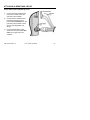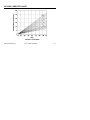
1
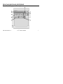
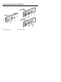
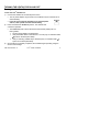
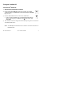
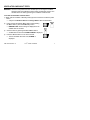
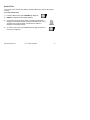
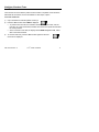
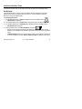
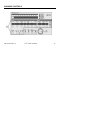
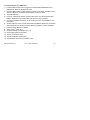
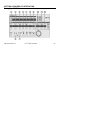
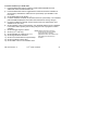
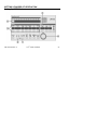
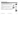
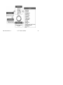
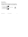
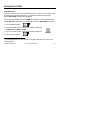
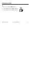
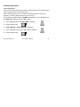
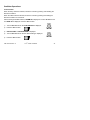
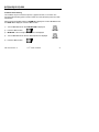
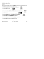
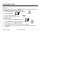
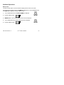
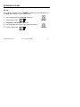
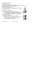
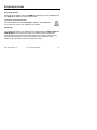
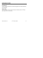
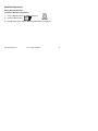
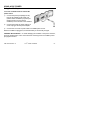
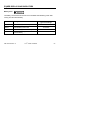
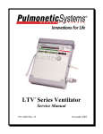
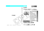
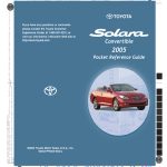
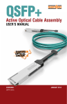
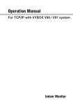
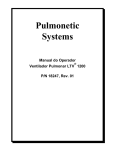
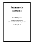
LTV® Series Ventilators
(LTV® 900, 950, and 1000)
Quick Reference Guide
ASSISTANCE
CareFusion Respiratory Systems
22745 Savi Ranch Parkway
Yorba Linda, California 92887-4645, USA
Tel: 763.398.8500
800.754.1914
Fax: 763.398.8403
Website: www.carefusion.com
Email:
[email protected]
P/N 19819-001 Rev. A
®
LTV Series Ventilators
ii
TABLE OF CONTENTS
Front and Side Panel Reference ................................................................................. 1
Front Panel Display and Description.......................................................................... 1
Side Panel Descriptions............................................................................................. 3
Turning the Ventilator On and Off .............................................................................. 5
Turning the Ventilator On .......................................................................................... 5
Turning the Ventilator Off .......................................................................................... 6
Ventilator Checkout Tests ........................................................................................... 7
Alarm Test ................................................................................................................. 8
Display Test ............................................................................................................... 9
Control Test ............................................................................................................. 10
Leak Test ................................................................................................................. 11
Vent Inop Alarm Test ............................................................................................... 12
Set Defaults ............................................................................................................. 13
Exit .......................................................................................................................... 14
Variable Controls........................................................................................................ 15
Setting Up Modes of Ventilation ............................................................................... 17
Setting Up Control Mode ......................................................................................... 17
Setting Up Assist/Control Mode ............................................................................... 19
Setting Up SIMV Mode ............................................................................................ 21
P/N 19819-001 Rev. A
®
LTV Series Ventilators
iii
Setting Up CPAP Mode ........................................................................................... 23
Setting Up NPPV Mode ........................................................................................... 25
Monitored Data ........................................................................................................... 27
Extended Features ..................................................................................................... 29
Using AC/DC Power ................................................................................................... 57
Using the AC Adapter .............................................................................................. 57
Using an External DC Power Source ....................................................................... 58
Power Displays and Indicators ................................................................................. 59
Attaching a Breathing Circuit .................................................................................... 63
Oxygen Computer Chart ............................................................................................ 65
Alarms ......................................................................................................................... 67
P/N 19819-001 Rev. A
®
LTV Series Ventilators
iv
FRONT AND SIDE PANEL REFERENCE
Front Panel Display and Description
P/N 19819-001 Rev. A
®
LTV Series Ventilators
1
A - Mode and Breath Selection – Selects ventilation modes. Selects breath types.
B - Power – Turns ventilator “On” or to “Standby.”
C - Variable Control Settings – Sets ventilation characteristics, such as Tidal Volume
and Breath Rate.
D - Display Window – Displays Alarm Messages, Monitored Data, Extended Features
menu.
E - Airway Pressure Display – Displays real-time airway circuit pressure.
F - Patient Effort Indicator – LED is lit briefly each time a patient trigger is detected.
G - Power Source – Displays power source and charge levels.
H - Variable Alarm Settings – Sets variable alarm levels.
I-
Alarm Silence/Reset – Silences audible alarms. Clears visual alarms.
J - Set Value Knob – Changes variable control settings. Navigates Extended
Features menu.
K - Special Controls – Activates special controls such as Manual Breath, Low
Pressure O2 Source, Insp/Exp Hold or Control Lock feature.
P/N 19819-001 Rev. A
®
LTV Series Ventilators
2
FRONT AND SIDE PANEL REFERENCE
Side Panel Descriptions
P/N 19819-001 Rev. A
®
LTV Series Ventilators
3
A - 22mm Outlet Port – Patient Breathing Circuit outlet port.
B - Flow Xducer – Flow Transducer high pressure sensing port.
C - Flow Xducer – Flow Transducer low pressure sensing port.
D - Exh Valve – Exhalation Valve drive line port.
E - Alarm Sounder Port
F - Cooling Fan
G - DC Input – External DC power port (earlier version)
or DC power port pigtail connector (current version).
H - Patient Assist – Patient Assist Call jack.
I-
Comm Port – Communications port.
J - O2 Inlet – Oxygen Inlet fitting.
K - Filter – Air Inlet.
P/N 19819-001 Rev. A
®
LTV Series Ventilators
4
TURNING THE VENTILATOR ON AND OFF
Turning the Ventilator On
To turn the LTV® ventilator on:
1)
Connect the ventilator to an external power source:
• The AC power adapter may be used or the ventilator may be connected to an
external battery.
• If you do not connect the ventilator to an external power
source, it will operate from the internal battery.
2)
Press and release the On/Standby button. The ventilator will
commence operation:
• The On/Standby LED is lit and the Power On Self Tests (POST) are run.
During POST;
• The front panel displays are illuminated.
• Verify the audible alarm is activated for 1 second (only on ventilators with a
symbol on the back panel label).
• Verify a confirming audible chirp is activated (only on ventilators with a
symbol on the back panel label).
Once POST is successfully completed, the ventilator begins operating using the
stored control settings.
3)
P/N 19819-001 Rev. A
®
LTV Series Ventilators
5
Turning the Ventilator Off
To turn the LTV® ventilator off:
1)
Disconnect the patient from the ventilator.
2)
Press and hold the On/Standby button for 3 seconds. The ventilator
ceases operating, the audible alarm sounds continuously and the Vent
Inop LED is lit.
3)
Press the Silence/Reset button to silence the audible alarm.
•
4)
Verify a confirming audible chirp is activated immediately after the
alarm is silenced (only on ventilators with a symbol on the back
panel label).
The ventilator continues to charge the internal battery as long as it is connected to
an external power source.
Note: The Vent Inop LED will remain lit for a minimum of 5 minutes and does not
affect battery life.
P/N 19819-001 Rev. A
®
LTV Series Ventilators
6
VENTILATOR CHECKOUT TESTS
WARNING - Disconnect the patient from the ventilator prior to running the Ventilator
Checkout tests and ventilate the patient using an alternative method. The
ventilator does not deliver gas during the Ventilator Checkout tests.
To enable the Ventilator Checkout menu:
1) Begin with the ventilator in Standby mode (off) and connected to a valid AC power
source.
• Verify that the External Power and Charge Status LEDs are illuminated.
2)
Press and hold the Monitor Select button. While holding
the Select button, press the On/Standby button.
• REMOVE PTNT alarm message is displayed and an
audible alarm is sounded.
3)
Clear the alarm by pressing the Silence/Reset button.
• Audible alarm is silenced and VENT CHECK is displayed.
4)
Press the Select button to move to the first test.
• The first Ventilator Checkout Test, ALARM, is
displayed.
P/N 19819-001 Rev. A
®
LTV Series Ventilators
7
Alarm Test
The alarm Test is used to verify that the audible alarm is working correctly.
1) Press the Select button while ALARM is displayed.
2) Verify the audible alarm is sounded.
•
If a Patient Assist Call System or Remote Alarm is connected via the
ventilator’s Patient Assist Port, verify the device also activates (audible/visual),
as specified by its manufacturer.
3) When the alarm has sounded for at least 2 seconds, press the
Select button again.
•
The audible alarm is silenced and the next menu item is displayed.
4) For ventilators with an audio sound symbol ( ) on the back panel label, verify a
confirming audible chirp occurs after the alarm is silenced.
P/N 19819-001 Rev. A
®
LTV Series Ventilators
8
Ventilator Checkout Tests
Display Test
The display Test is used to verify that the ventilator displays are working correctly.
To run the Display Test:
1)
Press the Select button while DISPLAY is displayed.
2)
All segments of the 7-segment control displays, all dots of the dot-matrix window
displays and all LEDs are illuminated.
•
•
3)
The External Power and Charge Status LEDs are tested and verified when
the AC adapter is connected to the ventilator (see page 7).
The Vent Inop LED is tested and verified during the Vent Inop Alarm Test (see
page 12).
To end the display test, press the Select button again and the
next menu item is displayed.
P/N 19819-001 Rev. A
®
LTV Series Ventilators
9
Control Test
The Control Test is used to verify that the ventilator buttons and controls are working
correctly.
To run the Control Test:
1)
Press the Select button while CONTROL is displayed.
2)
SELECT is displayed in the display windows.
3)
To test each control, press the button. The name of the button is
displayed in the display window. To test the Set Value knob, turn it
clockwise and counterclockwise. The direction of rotation is
displayed in the display window.
4)
To exit the control test, press the Select button again and the next
menu item is displayed.
P/N 19819-001 Rev. A
®
LTV Series Ventilators
10
Ventilator Checkout Tests
Leak Test
The Leak Test is used to test the patient circuit for leaks. The patient circuit should be
tested with all accessories, such as humidifiers or water traps, in place.
To run the Leak Test:
1)
Cap or otherwise occlude the patient circuit wye.
2)
Press the Select button while LEAK is displayed.
•
•
3)
To perform the Leak Test, the ventilator closes the exhalation valve, sets the
flow valve to a near-closed state, elevates the turbine motor speed and elevates
the circuit pressure.
At the conclusion of the test, the display shows LEAK xx.x pass or fail, where
xx.x is the measured leak.
To exit the Leak Test, press the Select button again and the next
menu item is displayed.
P/N 19819-001 Rev. A
®
LTV Series Ventilators
11
Vent Inop Alarm Test
The Vent Inop Alarm Test is used to verify that the Inop Alarm is working correctly.
To run the Vent Inop Alarm Test:
1) To run the Vent Inop Alarm Test, the ventilator must be on (running) for at least 60
seconds and the Ventilator Checkout menu must be enabled.
2) Turn the ventilator off by pressing and holding the On/Standby button for
a minimum of 3 seconds. DO NOT press the Silence/Reset button.
3) Observe the ventilator for 15 seconds.
• Listen for the alarm tone
• Watch the Vent Inop LED
4) For all ventilators, verify that both of the following conditions existed;
• The alarm tone sounded continuously for the full 15-second duration.
• The Vent Inop LED illuminated continuously for the full 15-second duration.
5) If a Patient Assist Call System or Remote Alarm is connected via the ventilator’s Patient
Assist Port, verify the device also activates (audible/visual), as
specified by its manufacturer.
6) Silence the alarm by pressing the Silence/Reset button.
7) For ventilators with an a audio sound symbol ( ) on the back panel
label, verify the following condition existed;
• A confirming audible chirp occurred after the alarm was silenced.
P/N 19819-001 Rev. A
®
LTV Series Ventilators
12
Ventilator Checkout Tests
When the Ventilator Checkout Tests have been completed, proceed to Exit for instructions
to exit the vent check mode, or see below concerning the use of the Set Defaults option.
Set Defaults
The Set Defaults option is used to reset user settable Controls and Extended Features
settings to their factory-set default values (see the LTV® Series Ventilators Operator’s
Manual for factory-set default values).
To set the default values:
1) Turn the Set Values knob until EXIT is displayed and press the Select button.
• VENT CHECK is displayed
2) Turn the Set Values knob until VENT OP is displayed and press the Select button.
3) Turn the Set Values knob until DEFAULTS is displayed and press the Select button.
• SET DEFAULTS is displayed.
4) Press the Select button while SET DEFAULTS is displayed.
• Except for the Language selected and the Date/Time settings and format, all user
settable Controls and Extended Features options are reset to their factory-set default
values.
• A DEFAULTS SET alarm will be generated the next time the ventilator is powered up
in normal ventilation mode (see Alarms, DEFAULTS SET for additional information).
P/N 19819-001 Rev. A
®
LTV Series Ventilators
13
Exit
To return to any of the VENT CHECK tests, turn the Set Value knob until the desired
test is displayed.
To Exit:
1)
Press the Select button while EXIT is displayed, and VENT CHECK
is displayed.
2)
Turn the Set Value knob until EXIT is displayed again.
3)
Press the Select button.
The Ventilator performs a Self Test (POST) and resumes normal operation.
P/N 19819-001 Rev. A
®
LTV Series Ventilators
14
VARIABLE CONTROLS
P/N 19819-001 Rev. A
®
LTV Series Ventilators
15
To set a variable control:
1) Select the control by pressing the associated button. The display for the selected
control will be displayed at normal brightness and all other control displays will be
dimmed.
2) Change the control value by rotating the Set Value Knob. Rotate
clockwise to increase and counter-clockwise to decrease the value.
3) The new control value goes into effect when the operator:
•
Presses the selected button again, or
•
Selects another control, or
•
Presses the Control Lock button, or
•
Waits 5 seconds
All controls will then return to their normal brightness.
P/N 19819-001 Rev. A
®
LTV Series Ventilators
16
SETTING UP MODES OF VENTILATION
Setting Up Control Mode
P/N 19819-001 Rev. A
®
LTV Series Ventilators
17
To set the ventilator up in Control mode:
Press the Select button twice to toggle the modes between Assist/Control and
SIMV/CPAP. Select the Assist/Control mode.
2) Press the Select button twice to toggle between Volume and Pressure ventilation.
®
Select Volume or Pressure, as desired. (Not available on the LTV 900.)
3) Set the Breath Rate.
4) If Volume ventilation is selected, set the Tidal Volume. The calculated peak flow
Vcalc is displayed in the window while Tidal Volume is being changed.
5) If Pressure ventilation is selected, set the Pressure Control. (Not available on the
LTV® 900.)
6) Set the Inspiratory Time. The calculated peak flow Vcalc is displayed in the window
while Inspiratory Time is being changed. Vcalc only applies to volume ventilation.
®
7) Set O2% (LTV 1000 only).
8) Set the Sensitivity to Off (dash “-“).
9) Set the High Pressure Limit alarm.
10) Set the Low Pressure alarm.
11) Set the Low Minute Volume alarm.
12) Set the PEEP control on the exhalation valve.
1)
P/N 19819-001 Rev. A
®
LTV Series Ventilators
18
SETTING UP MODES OF VENTILATION
Setting Up Assist/Control Mode
P/N 19819-001 Rev. A
®
LTV Series Ventilators
19
To set the ventilator up in Assist/Control mode:
Press the Select button twice to toggle the modes between Assist/Control and
SIMV/CPAP. Select the Assist/Control mode.
2) Press the Select button twice to toggle between Volume and Pressure ventilation.
®
Select Volume or Pressure, as desired. (Not available on the LTV 900).
3) Set the Breath Rate.
4) If Volume ventilation is selected, set the Tidal Volume. The calculated peak flow
Vcalc is displayed in the window while Tidal Volume is being changed.
5) If Pressure ventilation is selected, set the Pressure Control. (Not available on the
LTV® 900.)
6) Set the Inspiratory Time. The calculated peak flow Vcalc is displayed in the window
while Inspiratory Time is being changed. Vcalc only applies to volume ventilation.
®
7) Set O2%, (LTV 1000 only).
8) Set the Sensitivity to a setting from 1 to 9.
9) Set the High Pressure Limit alarm.
10) Set the Low Pressure alarm.
11) Set the Low Minute Volume alarm.
12) Set the PEEP control on the exhalation valve.
1)
P/N 19819-001 Rev. A
®
LTV Series Ventilators
20
SETTING UP MODES OF VENTILATION
Setting Up SIMV Mode
P/N 19819-001 Rev. A
®
LTV Series Ventilators
21
To set the Ventilator up in SIMV mode:
1)
2)
3)
4)
5)
6)
7)
8)
9)
10)
11)
12)
13)
Press the Select button twice to toggle the modes between Assist/Control and
SIMV/CPAP. Select the SIMV/CPAP mode.
Press the Select button to toggle between Volume and Pressure ventilation. Select
®
Volume or Pressure, as desired. (Not available on the LTV 900).
Set the Breath Rate.
If Volume ventilation is selected, set the Tidal Volume. The calculated peak flow
Vcalc is displayed in the window while Tidal Volume is being changed.
If Pressure ventilation is selected, set the Pressure Control. (Not available on the
LTV® 900.)
Set the Inspiratory Time. The calculated peak flow Vcalc is displayed in the window
while Inspiratory Time is being changed. Vcalc only applies to volume ventilation.
Set the Pressure Support, if desired.
Set O2% (LTV® 1000 only).
Set the Sensitivity to a setting from 1 to 9.
Set the High Pressure Limit alarm.
Set the Low Pressure alarm.
Set the Low Minute Volume alarm.
Set the PEEP control on the exhalation valve.
P/N 19819-001 Rev. A
®
LTV Series Ventilators
22
SETTING UP MODES OF VENTILATION
Setting Up CPAP Mode
P/N 19819-001 Rev. A
®
LTV Series Ventilators
23
To set the ventilator up in CPAP mode:
1) Press the Select button twice to toggle the modes between Assist/Control and
SIMV/CPAP. Select the SIMV/CPAP mode.
2) Press the Select button twice to toggle between Volume and Pressure ventilation for
Apnea backup. Select Volume or Pressure for Apnea backup. (Not available on the
LTV® 900).
3) Set the Breath Rate to Off (dashes “- -“).
4) If Volume ventilation is selected, set the Tidal Volume for Apnea backup. The calculated
peak flow Vcalc is displayed in the window while Tidal Volume is being changed.
5) If Pressure ventilation is selected, set the Pressure Control for Apnea backup. (Not
available on the LTV® 900.)
6) Set the Inspiratory Time for Apnea backup. The calculated peak flow Vcalc is displayed
in the window while Inspiratory Time is being changed. Vcalc only applies to volume
ventilation.
7) Set the Pressure Support, if desired.
NOTE: Although Tidal Volume, Pressure
Control and Insp Time are dimmed,
8) Set O2% (LTV® 1000 only).
they should be set to clinically
9) Set the Sensitivity to a setting from 1 to 9.
appropriate levels as the ventilator uses
10) Set the High Pressure Limit alarm.
these settings for Apnea back-up
ventilation.
11) Set the Low Pressure alarm for Apnea backup.
12) Set the Low Minute Volume alarm.
13) Set the PEEP control on the exhalation valve.
P/N 19819-001 Rev. A
®
LTV Series Ventilators
24
SETTING UP MODES OF VENTILATION
Setting Up NPPV Mode
P/N 19819-001 Rev. A
®
LTV Series Ventilators
25
To set the Ventilator up in NPPV mode:
1) Set the ventilator controls for Control, Assist/Control, SIMV, or CPAP mode, as
2)
3)
4)
5)
6)
7)
8)
9)
10)
11)
12)
13)
described in the preceding section.
Set the ventilator controls for Volume or Pressure ventilation, as described in the
preceding section.
Set all other ventilation parameters, as described in the previous section.
Set the High Pressure Limit alarm.
Enter Extended Features by pressing and holding the Monitor Select button for 3
seconds.
Turn the Set Value knob until VENT OP is displayed.
Press the Monitor Select button.
Turn the Set Value knob until NPPV Mode is displayed.
Press the Monitor Select button.
Turn the Set Value knob until NPPV On is displayed.
Press Monitor Select button.
The NPPV LED will be illuminated.
Exit the Extended Features menus by turning the Set Value knob until Exit is
displayed, and pressing Select button until monitored data is displayed in the
window.
P/N 19819-001 Rev. A
®
LTV Series Ventilators
26
MONITORED DATA
The monitored data displays may be automatically scrolled or manually scrolled. To
cycle through the available monitored data automatically from a halted scan, press the
Monitor Select button twice. Pressing the Select button once while scan is active shall
halt scanning and the currently display monitor shall remain in the display window. Each
time you press the button once; the next data item in the list will be displayed. To
resume scan, press the scan button twice. The monitored data is displayed in the
following order.
Display
PIP
MAP
PEEP
f
Vte
Description
Displays the Peak Inspiratory Pressure measured during the
inspiratory phase. PIP is not updated for spontaneous breaths.
Displays a running average of the airway pressure for the last 60
seconds.
Displays the pressure in the airway circuit at the end of exhalation.
Displays the breaths per minute and includes all breath types.
Displays the exhaled tidal volume as measured at the patient wye.
P/N 19819-001 Rev. A
®
LTV Series Ventilators
27
Display
VE
I:E
Vcalc
Description
Displays the exhaled tidal volume for the last 60 seconds as calculated
from the last 8 breaths.
Displays the ratio between measured inspiratory time and measured
exhalation time. Both normal and inverse I:E Ratios are displayed.
Is based on the Tidal Volume and Inspiratory Time settings. Displayed
when selected and whenever Tidal Volume or Inspiratory Time is
selected for change.
P/N 19819-001 Rev. A
®
LTV Series Ventilators
28
EXTENDED FEATURES
Navigating the Extended Features Menus:
To enter the Extended Features menu (in normal ventilation mode),
press and hold the Monitor Select button for three seconds.
To view the next item in a menu, turn the Set Value knob
clockwise.
To view the previous item, turn the Set Value knob counterclockwise.
To enter a menu item or select a setting, press the
Select button.
To exit a menu, turn the Set Value knob until the EXIT option is
displayed, then press the Select button or press Control Lock.
P/N 19819-001 Rev. A
®
LTV Series Ventilators
29
P/N 19819-001 Rev. A
®
LTV Series Ventilators
30
EXTENDED FEATURES
Alarm Operations
Alarm Volume
After accessing Extended Features, ALARM OP is displayed. Press the Select button
and ALARM VOL is displayed.
1)
Press the Select button.
2)
VOL xx dBA is displayed, where xx is the currently set volume.
3)
Turn the Set Value knob until the desired setting is displayed.
4)
Press the Select button.
P/N 19819-001 Rev. A
®
LTV Series Ventilators
31
Alarm Operations
Apnea Interval
After accessing Extended Features, ALARM OP is displayed. Press the Select button
and ALARM VOL is displayed. Turn the Set Value knob until APNEA INT is displayed.
1)
Press the Select button.
2)
APNEA xx sec is displayed, where xx is the currently set Apnea interval.
3)
Turn the Set Value knob until the desired setting is displayed.
4)
Press the Select button.
P/N 19819-001 Rev. A
®
LTV Series Ventilators
32
EXTENDED FEATURES
Alarm Operations
High Pressure Alarm Delay
This menu item is used to select immediate or delayed audible notification for High
Pressure alarms.
After accessing Extended Features, ALARM OP is displayed. Press the Select button
and ALARM VOL is displayed. Turn the Set Value knob until HP DELAY is displayed.
1)
Press the Select button.
2)
Turn the Set Value knob until the desired setting is displayed,
NO DELAY, DELAY 1 BRTH, or DELAY 2 BRTH.
3)
Press the Select button.
P/N 19819-001 Rev. A
®
LTV Series Ventilators
33
Alarm Operations
Low Peak Pressure Alarm
This item is used to select the type of breaths that the Low Pressure Alarm applies to.
After accessing Extended Features, ALARM OP is displayed. Press the Select button
and ALARM VOL is displayed. Turn the Set Value knob until LPP ALARM is displayed.
1)
Press the Select button.
2)
Turn the Set Value knob until the desired setting is displayed,
ALL BREATHS, VC/PC ONLY.
3)
Press the Select button.
P/N 19819-001 Rev. A
®
LTV Series Ventilators
34
EXTENDED FEATURES
Alarm Operations
1
High PEEP Alarm
This menu item is used to set a high PEEP alarm value. When the current PEEP value
exceeds the set high PEEP alarm value, an audible alarm will be sounded and a
flashing HIGH PEEP message will be displayed.
After accessing Extended Features, ALARM OP is displayed. Press the Select button
and ALARM VOL is displayed. Turn the Set Value knob until HIGH PEEP is displayed.
1) Press the Select button.
2) Turn the Set Value knob until the desired setting is displayed,
HI PEEP OFF or PEEP xx cmH2O.
3) Turn the Set Value knob until the desired setting is displayed.
4) Press the Select button.
1
The HIGH PEEP alarm is only available on ventilators with software version 3.15 or
higher installed.
P/N 19819-001 Rev. A
®
LTV Series Ventilators
35
Alarm Operations
PNT Assist2
This menu item is used to configure the patient Assist Port output signal to be
generated for use with remote alarm systems.
After accessing Extended Features, ALARM OP is displayed. Press the Select button
and ALARM VOL is displayed. Turn the Set Value knob until PNT ASSIST is displayed.
1) Press the Select button.
2) Turn the Set Value knob until the desired setting is displayed,
NORMAL or PULSE.
3) Press the Select button.
2
The PNT ASSIST option is only available on ventilators with software version 3.15 or
higher installed.
P/N 19819-001 Rev. A
®
LTV Series Ventilators
36
EXTENDED FEATURES
Alarm Operations
Exit
To return to the top of the ALARM OP menu:
1)
Turn the Set Value knob until EXIT is displayed.
2)
Press the Select button while EXIT is displayed
P/N 19819-001 Rev. A
®
LTV Series Ventilators
37
Ventilator Operations
Variable Rise Time
The variable Rise Time option is used to select the rise time profile for Pressure Control
and Pressure Support breaths. The rise time profiles are numbered 1 through 9, where
1 is the fastest rise time and 9 is the slowest rise time.
After accessing Extended Features, ALARM OP is displayed. Turn the Set Value knob
until VENT OP is displayed. Press the Select button, and RISE TIME is displayed.
1)
Press the Select button.
2)
PROFILE x is displayed, where x is the currently set value.
3)
Turn the Set Value knob until the desired Rise Time Profile is displayed.
4)
Press the Select button.
P/N 19819-001 Rev. A
®
LTV Series Ventilators
38
EXTENDED FEATURES
Ventilator Operations
Variable Flow Termination
The Variable Flow Termination is used to select the percentage of peak flow used for cycling
Pressure Support breaths. Pressure Support breaths are cycled from inspiration to
exhalation when the flow reaches the set percentage of the peak flow, or when flow goes
below 2 lpm.
When Pressure Control Flow Termination is enabled, the Variable Flow Termination setting
is used for flow termination of Pressure Control breaths as well.
After accessing Extended Features, ALARM OP is displayed. Turn the Set Value knob until
VENT OP is displayed. Press the Select button.
1)
Turn the Set Value knob until FLOW TERM is displayed.
2)
Press the Select button.
3)
% OF PEAK xx is displayed, where xx is the current Flow Termination setting.
4)
Turn the Set Value knob until the desired Flow Termination percentage
is displayed.
5)
Press the Select button.
P/N 19819-001 Rev. A
®
LTV Series Ventilators
39
Ventilator Operations
Variable Time Termination
The Variable Time Termination is used to select maximum inspiratory time for cycling
Pressure Support breaths. Pressure Support breaths are cycled from inspiration to
exhalation, if this time is reached before the flow reaches the set percentage of the
peak flow. When a breath is cycled based on the time setting, the Pressure Support
display is flashed briefly.
After accessing Extended Features, ALARM OP is displayed. Turn the Set Value knob
until VENT OP is displayed. Press the Select button.
1)
Turn the Set Value knob until TIME TERM is displayed.
2)
Press the Select button.
3)
TERM x.x sec is displayed, where xx is the current Time Termination setting.
4)
Turn the Set Value knob until the desired Time Termination is
displayed.
5)
Press the Select button.
P/N 19819-001 Rev. A
®
LTV Series Ventilators
40
EXTENDED FEATURES
Ventilator Operations
Pressure Control Flow Termination
The Pressure Control Flow Termination option is used to enable or disable flow
termination for Pressure Control breaths.
When this option is on, Pressure Control breaths are cycled at the set percentage of
peak flow, if it is reached before the set Inspiratory Time elapses. The percentage of
peak flow is set in the Variable Flow Termination option.
After accessing Extended Features, ALARM OP is displayed. Turn the Set Value knob
until VENT OP is displayed. Press the Select button.
1)
2)
Turn the Set Value knob until PC FLOW TERM is displayed.
Press the Select button.
3)
4)
PC FLOW ON or PC FLOW OFF is displayed.
Turn the Set Value knob until the desired state is displayed.
5)
Press the Select button.
P/N 19819-001 Rev. A
®
LTV Series Ventilators
41
Ventilator Operations
Leak Compensation
Use the Leak Compensation option to enable or disable tracking of the Baseline Flow to
improve triggering when a circuit leak is present.
When Leak Compensation is on, the system is gradually adjusted to maintain set
sensitivity, if the leak is stable and there is no auto cycling.
After accessing Extended Features, ALARM OP is displayed. Turn the Set Value knob
until VENT OP is displayed. Press the Select button.
1)
Turn the Set Value knob until LEAK COMP is displayed.
2)
Press the Select button.
3)
LEAK COMP ON or LEAK COMP OFF is displayed.
4)
Turn the Set Value knob until the desired state is displayed.
5)
Press the Select button.
P/N 19819-001 Rev. A
®
LTV Series Ventilators
42
EXTENDED FEATURES
Ventilator Operations
NPPV Mode
After accessing Extended Features, ALARM OP is displayed. Turn the Set Value knob
until VENT OP is displayed. Press the Select button.
1)
Turn the Set Value knob until the NPPV MODE is displayed.
2)
Press the Select button.
3)
NPPV MODE ON or NPPV MODE OFF is displayed.
4)
Turn the Set Value knob until the desired state is displayed.
5)
Press the Select button.
P/N 19819-001 Rev. A
®
LTV Series Ventilators
43
Ventilator Operations
Control Unlock
When the Easy method is selected, unlock the controls by pressing and releasing the
Control Lock button.
When the Hard method is selected, unlock the controls by pressing and holding the
Control Lock button for 3 seconds.
After accessing Extended Features, ALARM OP is displayed. Turn the Set Value knob
until VENT OP is displayed. Press the Select button.
1)
Turn the Set Value knob until CTRL UNLOCK is displayed.
2)
Press the Select button.
3)
UNLOCK EASY or UNLOCK HARD is displayed.
4)
Turn the Set Value knob until the desired setting is displayed.
5)
Press the Select button.
P/N 19819-001 Rev. A
®
LTV Series Ventilators
44
EXTENDED FEATURES
Ventilator Operations
Language Selection
After accessing Extended Features, ALARM OP is displayed. Turn the Set Value knob
until VENT OP is displayed. Press the Select button.
1)
Turn the Set Value knob until LANGUAGE is displayed.
2)
Press the Select button.
3)
ENGLISH or the currently selected language is displayed.
4)
Turn the Set Value knob until the desired language is displayed.
5)
Press the Select button.
P/N 19819-001 Rev. A
®
LTV Series Ventilators
45
Ventilator Operations
Software Versions
After accessing Extended Features, ALARM OP is displayed. Turn the
Set Value knob until VENT OP is displayed. Press the Select button.
Turn the Set Value knob until VER xx.xx.xx is displayed, where
xx.xx.xx is the current software version.
Usage Meter
After accessing Extended Features, ALARM OP is displayed. Turn the
Set Value knob until VENT OP is displayed. Press the Select button.
Turn the Set Value knob until USAGE xxxxx.x is displayed, where
xxxxx.x is the current number of hours the ventilator has been in
operation.
P/N 19819-001 Rev. A
®
LTV Series Ventilators
46
EXTENDED FEATURES
Ventilator Operations
Communications Setting
The ventilator may be connected to printer, a graphics monitor, or a modem. The
Communications Setting option is used to select the communications protocol for data
transmission.
After accessing Extended Features, ALARM OP is displayed. Turn the Set Value knob
until VENT OP is displayed. Press the Select button.
1)
Turn the Set Value knob until COM SETTING is displayed.
2)
Press the Select button.
3)
MONITOR or the currently selected protocol is displayed.
4)
Turn the Set Value knob until the desired protocol is displayed.
5)
Press the Select button.
P/N 19819-001 Rev. A
®
LTV Series Ventilators
47
Ventilator Operations
Set Date
After accessing Extended Features, ALARM OP is displayed. Turn the Set Value knob
until VENT OP is displayed. Press the Select button.
1)
Turn the Set Value knob until SET DATE is displayed.
2)
Press the Select button.
3)
The current date is displayed in the currently selected date format.
4)
Press the Control Lock button to exit, or continue to modify the Date.
To modify the Date:
1)
Press the Select button, YEAR xxxx is displayed.
2)
3)
4)
5)
6)
7)
Turn the Set Value knob until the desired year is displayed.
Press the Select button, MONTH xx is displayed.
Turn the Set Value knob until the desired month is displayed.
Press the Select button, DAY xx is displayed.
Turn the Set Value knob until the desired day is displayed.
Press the Select button to accept the new date.
P/N 19819-001 Rev. A
®
LTV Series Ventilators
48
EXTENDED FEATURES
Ventilator Operations
Set Time
After accessing Extended Features, ALARM OP is displayed. Turn the Set Value knob
until VENT OP is displayed. Press the Select button.
1) Turn the Set Value knob until SET TIME is displayed.
2)
Press the Select button.
3)
4)
The current time is displayed.
Press the Control Lock button to exit, or
To modify the Time:
1)
Press the Select button, HOUR xx is displayed.
2)
Turn the Set Value knob until the desired hour is displayed.
3)
4)
5)
Press the Select button, MIN xx is displayed.
Turn the Set Value knob until the desired minute is displayed.
Press the Select button to accept the new time. The seconds are automatically
reset to 00.
P/N 19819-001 Rev. A
®
LTV Series Ventilators
49
Ventilator Operations
Date Format
The Date Format option is used to select the display format for the current date.
After accessing Extended Features, ALARM OP is displayed. Turn the Set Value knob
until VENT OP is displayed. Press the Select button.
1)
Turn the Set Value knob until DATE FORMAT is displayed.
2)
Press the Select button.
3)
MM/DD/YYYY or the currently selected date format is displayed.
4)
Turn the Set Value knob until the desired format is displayed.
5)
Press the Select button.
P/N 19819-001 Rev. A
®
LTV Series Ventilators
50
EXTENDED FEATURES
Ventilator Operations
PIP LED
After accessing Extended Features, ALARM OP is displayed. Turn the Set Value knob
until VENT OP is displayed. Press the Select button.
1)
Turn the Set Value knob until PIP LED is displayed.
2)
Press the Select button.
3)
PIP LED ON or PIP LED OFF is displayed.
4)
Turn the Set Value knob until the desired setting is displayed.
5)
Press the Select button.
P/N 19819-001 Rev. A
®
LTV Series Ventilators
51
Ventilator Operations
Model Number / Serial Number
After accessing Extended Features, ALARM OP is displayed. Turn the Set Value knob
until VENT OP is displayed. Press the Select button.
®
To view the LTV model number:
Turn the Set Value knob until LTV XXXX is displayed, where XXXX is
the model of the ventilator.
To view the LTV® serial number:
1) Press the Select button while LTV XXXX is displayed.
• The serial number is displayed on the left side of the display
area as XXXXXX, where XXXXXX is the serial number of the ventilator.
2) Press the Select button to return to the model number option.
To view LTM™ compatibility:
1) Press the Select button while LTV XXXX is displayed.
•
2)
LTM will be displayed if software and internal hardware in the
LTV® Ventilator are LTM™ compatible.
Press the Select button to return to the model number.
P/N 19819-001 Rev. A
®
LTV Series Ventilators
52
EXTENDED FEATURES
Ventilator Operations
Valve Home Position
After accessing Extended Features, ALARM OP is displayed. Turn the Set Value knob
until VENT OP is displayed. Press the Select button.
To view the valve home position:
Turn the Set Value knob until Vhome XXX is displayed, where XXX is the
home position for the flow valve installed in the ventilator.
Set Defaults
The Set Defaults option is only displayed and accessed through the VENT CHECK and
VENT MTNCE menus and is used to reset user settable Controls and Extended
Features settings to their factory-set default values. See Ventilator Checkout Tests,
Set Defaults for instructions on how to set default values and the LTV® Series
Ventilators Operator’s Manual for factory-set default values.
P/N 19819-001 Rev. A
®
LTV Series Ventilators
53
Ventilator Operations
Exit
To return to the top of the VENT OP menu:
1)
Turn the Set Value knob until EXIT is displayed.
2)
Press the Select button.
XDCR ZERO
This item is used to view the Transducer Autozero results and schedule the Transducer
Autozero to be run (see the LTV® Series Operator’s Manual for more information).
P/N 19819-001 Rev. A
®
LTV Series Ventilators
54
EXTENDED FEATURES
Ventilator Operations
RT XDCR DATA
This menu displays the Real Time Transducer Data (please see the Service Manual for
more information).
EVENT TRACE
®
This menu displays the Events Codes stored by the ventilator (see the LTV Series
Service Manual for more information).
P/N 19819-001 Rev. A
®
LTV Series Ventilators
55
Ventilator Operations
Exiting Extended Features
To return to Monitored Parameters:
1)
Turn the Set Value knob until EXIT is displayed.
2)
Press the Select button.
3)
Repeat Steps 1 and 2 until the Monitored Parameters are displayed.
P/N 19819-001 Rev. A
®
LTV Series Ventilators
56
USING AC/DC POWER
Using the AC Adapter
To run the ventilator from an external AC
power source.
1)
Connect the power jack (straight or 90°)
from the AC adapter to the power port
(earlier version ventilators) or power port
pigtail connector (current version
ventilators) on the left side of the ventilator.
2)
Connect the proper AC power cable (110
or 220 V plug) to the AC power adapter.
3)
Connect the 110 or 220 V power cable to a suitable power source.
While the ventilator is plugged in, the internal battery is continuously charged.
CAUTION: Release Button – To avoid damaging the ventilator or the power connector,
press the release button on the connector before removing it from the ventilator power
port pigtail connector.
P/N 19819-001 Rev. A
®
LTV Series Ventilators
57
Using an External DC Power Source
To run the ventilator from an external DC power source.
1)
Connect the power port of the external DC power adapter cable to the power port
on the left side of the ventilator (earlier version ventilators), or the power port pigtail
connector (current version ventilators).
2)
Connect the DC jack to the DC power source.
P/N 19819-001 Rev. A
®
LTV Series Ventilators
58
POWER DISPLAYS AND INDICATORS
Indicators
Battery Level
The Battery Level indicator shows the level of available internal battery power while
running from the internal battery.
Approximate Battery Time
@ nominal settings
LED Color
Battery Level
Green
Internal battery level is acceptable
45 minutes
Amber
Internal battery level is low
10 minutes
Red
Off
Internal battery level is critically low
Ventilator is running on AC or
External Battery
5 minutes
P/N 19819-001 Rev. A
®
LTV Series Ventilators
59
Indicators
Charge Status
When the ventilator is plugged into an External Power source, it automatically charges
the internal battery.
LED Color
Flashing
Amber
Green
Amber
Red
Charge Status
The ventilator is performing pre-charge qualification testing of the
battery prior to starting the charge process. This happens when
external power is first applied to the ventilator. The qualification
process normally takes a few seconds but may take up to an hour
on a deeply discharged battery.
The internal battery is charged to full level.
The battery has not reached a full charge level and is still charging.
The ventilator has detected a charge fault or internal battery fault.
The internal battery cannot be charged. Contact your CareFusion
Certified Service Technician.
P/N 19819-001 Rev. A
®
LTV Series Ventilators
60
POWER DISPLAYS AND INDICATORS
Indicators
External Power
The External Power indicator shows the level of external power while the ventilator is
operating from an external power source. When the ventilator is running from the
internal battery, the External Power indicator is off. When running from external power,
the indicator shows the following levels.
LED Color
Power Level
Green
External Power level is acceptable
Amber
External Power level is low
External power may be provided by connecting the ventilator to an external battery or to
an external AC power source.
P/N 19819-001 Rev. A
®
LTV Series Ventilators
61
This page intentionally left blank
P/N 19819-001 Rev. A
®
LTV Series Ventilators
62
ATTACHING A BREATHING CIRCUIT
How to attach a patient breathing circuit.
1)
Connect the main breathing tube
to the 22 mm outlet port on the
right side of the ventilator.
2)
Connect the two exhalation flow
transducer sense lines to the
ports marked Flow Xducer on the
right side of the ventilator. These
are non-interchangeable Luer
fittings.
3)
Connect the Exhalation Valve
driver line to the port marked Exh
Valve on the right side of the
ventilator.
P/N 19819-001 Rev. A
®
LTV Series Ventilators
63
This page intentionally left blank
P/N 19819-001 Rev. A
®
LTV Series Ventilators
64
OXYGEN COMPUTER CHART
P/N 19819-001 Rev. A
®
LTV Series Ventilators
65
Oxygen Computer Chart
To determine O2 Input Flow:
1) Find the desired FIO2 on the horizontal axis.
2)
Project up to the minute volume.
3)
Project horizontally to the left vertical axis and read the oxygen flow.
To determine O2 Concentration:
1)
Find the O2 input flow on the vertical axis.
2)
Project horizontally right to the minute volume.
3)
Project vertically down to the horizontal axis and read the FIO2.
P/N 19819-001 Rev. A
®
LTV Series Ventilators
66
ALARMS
How to Silence and Reset Alarms
To silence an alarm, press the Silence Reset button.
To reset an alarm that has been corrected, press the Silence Reset button
again.
Alarm
Cause
APNEA XX bpm Occurs when the time since the last breath
Solution
Reevaluate the
start exceeds the set Apnea Interval. When patient’s condition.
an Apnea alarm occurs, the ventilator will
enter Apnea Back up ventilation mode.
Reevaluate ventilator
settings.
APNEA
An Apnea alarm has occurred and cleared
The ventilator is no longer in Apnea Backup mode.
Reevaluate the
patient’s condition.
Reevaluate ventilator
settings.
P/N 19819-001 Rev. A
®
LTV Series Ventilators
67
Alarm
BAT EMPTY
BATTERY LOW
DEFAULTS
Cause
Solution
Occurs when the ventilator is operating
from the internal battery power and the
batter charge level is critically low. This
alarm can be temporarily silenced but
cannot be cleared.
Occurs when the ventilator is operating
from internal battery power and the battery
charge level is low.
Attach the ventilator to
external AC or DC
power.
Occurs during POST when the ventilator
detects an invalid setting stored in nonvolatile memory.
DEFAULTS SET Occurs when the ventilator is first powered
up after the SET DEFAULTS option has
been used to reset all controls and
extended features settings to their factoryset default values.
P/N 19819-001 Rev. A
®
LTV Series Ventilators
Attach the ventilator to
external AC or DC
power.
Reevaluate power
requirements.
Push the
Silence/Reset button
twice to reset alarm.
Reevaluate ventilator
settings.
Push the
Silence/Reset button
twice to reset alarm.
Reevaluate ventilator
settings.
68
Alarms
Alarm
DISC/SENSE
HIGH O2 PRES
P/N 19819-001 Rev. A
Cause
Occurs when the ventilator detects one of
the following conditions:
•
The patient circuit or proximal
pressure sense line has become
disconnected.
•
The low side exhalation flow
transducer sense line has become
disconnected.
•
The proximal pressure sense line is
pinched or occluded.
Occurs when the average oxygen inlet
pressure exceeds the acceptable limit for
the type of oxygen source.
®
LTV Series Ventilators
Solution
Check Patient Circuit
assembly for
disconnects.
Check pressure
sensing lines for
occlusions.
Reduce O2 inlet
pressure.
69
Alarm
3
HIGH PEEP
HIGH PRES
HW Fault
3
Cause
Occurs when the ventilator detects one of
the following conditions:
•
The patient circuit positive end
expiratory pressure (PEEP) exceeds
the High PEEP alarm setting.
•
Patient Circuit, Exhalation valve
and/or PEEP valve occluded.
Occurs when the circuit pressure exceeds
the set High Pressure Limit setting.
Occurs when the ventilator detects a
problem with the ventilator hardware.
Solution
Reevaluate ventilator
settings.
Disassemble, clean
and reassemble the
Patient Circuit,
Exhalation Valve and
PEEP Valve.
Reevaluate ventilator
settings.
Inspect Patient Circuit
for occlusions or kinks.
Reevaluate patient.
If alarm reoccurs,
contact your Service
Rep or CareFusion.
The HIGH PEEP alarm is only available on ventilators with software version 3.15 or
higher installed.
P/N 19819-001 Rev. A
®
LTV Series Ventilators
70
Alarms
Alarm
INOP
LOCKED
LOW MIN VOL
Cause
Solution
A ventilator INOP occurs when:
•
The ventilator is switched from On to
Standby.
•
The ventilator detects any condition
that is deemed to make the ventilator
unsafe.
If an INOP alarm
occurs during
operation, remove
ventilator from service
and contact your
Service Rep.
The LOCKED message is displayed when
a button is pressed while the controls are
locked. No audible alarm is given.
Press the Control Lock
button.
Occurs when the exhaled minute volume is
less than the set Low Minute Volume.
If locked alert
continues, press and
hold the Control Lock
button for three
seconds.
Examine Exhalation
Valve body for
disconnects.
Reevaluate patient.
P/N 19819-001 Rev. A
®
LTV Series Ventilators
71
Alarm
LOW O2 PRES
Cause
Occurs when the average oxygen inlet
pressure is less than the minimum
acceptable inlet pressure of 35 PSIG.
LOW PRES
Occurs when the peak inspiratory pressure
for a machine or assist breath is less than
the Low Pressure setting.
NO CAL DATA,
NO CAL
Occurs when the ventilator detects invalid
or missing calibration records on power up.
POWER LOST
Occurs when the ventilator is operating on
external power and the voltage drops
below the useable level and switches to
internal battery operation.
P/N 19819-001 Rev. A
®
LTV Series Ventilators
Solution
Increase O2 inlet
pressure.
If using O2 cylinder,
replace used cylinder
with a new one.
Examine Patient
Circuit for disconnect.
Reevaluate ventilator
settings.
Reevaluate patient.
Remove ventilator
from service, perform
Calibration procedure.
Evaluate power
requirements.
Attach ventilator to an
external AC or DC
power source.
72
Alarms
Alarm
POWER LOW
REMOVE PTNT
RESET
4
Cause
Occurs when the ventilator is operating on
external power and the voltage drops to the
low level.
Occurs when the ventilator is powered up
in the Ventilator Checkout or Ventilator
Maintenance modes. The ventilator is not
delivering gas.
A RESET alarm occurs if the ventilator
restarts following a condition other than
being shut down by pressing the
On/Standby button.
Solution
Evaluate power
requirements.
Ensure patient is
disconnected from
ventilator and is being
ventilated by
alternative means.
May be caused by
Internal Battery
depletion during
operation4 or ESD. If
the problem reoccurs,
remove from service
and contact your
Service Rep or
CareFusion
Only available on ventilators with software version 3.13 or higher installed.
P/N 19819-001 Rev. A
®
LTV Series Ventilators
73
Alarm
XDCR FAULT
P/N 19819-001 Rev. A
Cause
Occurs when a transducer autozero test
fails.
®
LTV Series Ventilators
Solution
Press Silence/Reset
button twice to reset
alarm. If problem
occurs frequently,
remove from service
and contact your
Service Rep. or
CareFusion.
74
CareFusion Respiratory Systems
22745 Savi Ranch Parkway
Yorba Linda, California 92887-4645, USA
Tel: 763.398.8500
800.754.1914
Fax: 763.398.8403
www.carefusion.com