1
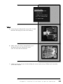
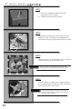
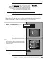
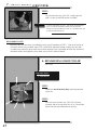
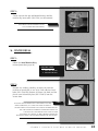
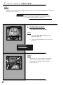
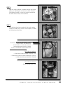
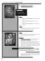
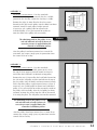
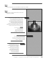
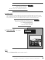
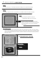
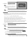
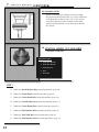
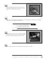
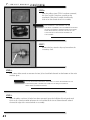
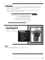
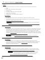
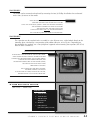
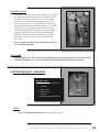
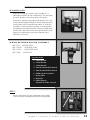
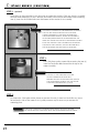
7.
SERVICE
MANUAL
7.
SERVICE MANUAL
IMPORTANT
BEFORE PROCEEDING WITH ANY
REPAIR, REPLACEMENT OR CLEANING,
THE POWER MUST BE TURNED OFF
AND THE MACHINE MUST BE
UNPLUGGED FROM THE
LOCAL POWER SOURCE!
➤ MAIN HOUSING FRAME
– SPECIAL ORDER ONLY
WARNING
23
REMOVING THE MAIN HOUSING FROM THE BODY OF THE
MACHINE VOIDS WARRANTY. THIS SHOULD ONLY BE DONE
IF ABSOLUTELY NECESSARY AND ONLY IF AUTHORIZED BY A
STORM CERTIFIED SURFACE FACTORY MECHANIC.
REQUIRED TOOLS:
1. 13mm Socket Wrench
2. 8mm Wrench
3. Phillips Head Screwdriver
4. 8.5 - 10” Socket Extender
5. 3” Paint Scraper
STEP 1:
A. Locate the green inductive lid sensor (SKU SF11LID)
located in the top right, inside of the housing.
B. Follow wiring on inside of control housing and
disconnect the green inductive lid sensor
(SKU SF11LID) from circuit board.
C. Unbolt and remove the two (2) bolts holding the sensor in place using a Phillips head screwdriver
and an 8mm wrench.
STORM’S SURFACE FACTORY SERVICE MANUAL
24
7.
SERVICE MANUAL (CONTINUED)
STEP 2:
A. Locate the stabilization bolt in the back,
right corner of the machine.
B. Unbolt and remove from machine.
STEP 3:
Disconnect the water hose (SKU SFHOSE32) and
polish hose (SKU SFHOSE33) located behind the
main drum using the Quick-Connect Release System.
STEP 4:
Remove the ten (10) 13mm bolts, washers, and lock
washers from the inside of the housing.
NOTE
THESE HAVE BEEN SECURED WITH SILICONE AND
WILL REQUIRE CLEANING BEFORE RE-INSTALLATION.
STEP 5:
Remove silicone seal with paint scraper by forcing
the scraper between the housing and the aluminum
plate attached to the main frame.
NOTE
25
IT MAY BE NECESSARY TO LOOSEN THE FOUR (4)
BOLTS IN THE ELECTRICAL HOUSING TO REMOVE
THE MAIN BALL HOUSING
USE EXTREME CAUTION WHEN BREAKING THE SILICONE SEAL.
SCRAPING THE PAINT, SCRATCHING THE METAL, BENDING THE HOUSING,
OR ALUMINUM PLATE CAN CAUSE WATER LEAKS AFTER RE-INSTALLATION.
ALSO, BE AWARE OF WHERE THE BALL RETAINER ASSEMBLY, WATER &
POLISH HOSE ASSEMBLY, DRAIN HOSE ASSEMBLY, AND THE
PLUNGER ASSEMBLY ARE LOCATED; FORCING THE SCRAPER TOO FAR UNDER THE
HOUSING FRAME CAN DAMAGE THESE ASSEMBLIES.
NOTE
RE-ASSEMBLY NOTES:
Before reversing STEPS 4 through 1, pay special attention to the aluminum plate, the bottom of the main
housing frame, and the bolts from STEP 3 – these all need to be thoroughly cleaned and scraped of all
remaining silicone. Failure to properly clean these parts can result in water leakage issues.
➤ METAL RETAINER RING
(SKU SF9)
REQUIRED TOOLS:
1. 6mm Allen Wrench
STEP 1:
Locate the two (2) allen hex head bolts located on the
side of the metal retainer ring on the retainer ring inner
collar (SKU SF9A).
DUE TO CORROSION, THESE BOLTS MAY BE EXTREMELY TIGHT.
USE CAUTION WHEN REMOVING.
NOTE
STORM’S SURFACE FACTORY SERVICE MANUAL
26
7.
SERVICE MANUAL (CONTINUED)
STEP 2:
Lift metal retainer ring (SKU SF9) straight upward
until it is clear of the ball retainer assembly.
NOTE
AS WITH THE BOLTS IN STEP 1, THE METAL RETAINER RING
(SKU SF9) MAY BE EXTREMELY DIFFICULT TO REMOVE.
TWISTING THE ASSEMBLY IN PLACE AS IT IS LIFTED MAY AID
IN THE REMOVAL PROCESS.
RE-ASSEMBLY NOTES:
Reverse STEPS as normal for re-installation paying special attention to STEP 1: Due to the design of
the metal retainer ring, the bolts from STEP 1 need to be tightened enough to keep the ring from
assembly from turning in place while the machine operates, but not enough to break the machined
aluminum collar; over-tightening these bolts can cause this collar to break.
➤ RETAINER RING INNER COLLAR
(SKU SF9A)
REQUIRED TOOLS:
1. 13mm Wrench
STEP 1:
Follow the Metal Retainer Ring removal procedure
(page 26).
STEP 2:
After the metal retainer ring (SKU SF9) has been
removed, loosen and remove the six (6) 13mm bolts
located on the top and bottom of the ring.
27
STEP 3:
Gently separate the top and bottom bracing until the
retainer ring inner collar (SKU SF9A) can be removed.
THESE BOLTS MAY BE EXTREMELY TIGHT.
USE CAUTION WHEN REMOVING.
NOTE
➤ CENTER DRUM
– SPECIAL ORDER ONLY
STEP 1:
Follow the Metal Retainer Ring
removal procedure (page 26).
REQUIRED TOOLS:
1. 5mm Allen Wrench
2. 6mm Allen Wrench
STEP 2:
Remove any sanding, polishing, or foam pads from the
machine to reveal four (4) sets of (4) 5mm allen hex head
bolts (SKU SF44SSB). Remove all sixteen (16) bolts and the
plastic sewn Velcro disk plate (SKU SF44V3) from the
center drum.
NOTE
SINCE THE VELCRO DISKS HAVE THE TENDENCY TO SPIN
WHEN UNBOLTING, IT IS TYPICALLY EASIER TO HOLD A
SECOND DISK IN PLACE WHILE YOU LOOSEN THE PRIMARY UNIT
YOU ARE CURRENTLY WORKING ON BEFORE MOVING TO
THE NEXT UNIT. THIS PROCESS WILL MAKE IT EASIER
TO LOOSEN ALL SIXTEEN (16) BOLTS BEFORE COMPLETELY
REMOVING THEM. THE SAME TRICK WORKS FOR TIGHTENING.
STORM’S SURFACE FACTORY SERVICE MANUAL
28
7.
SERVICE MANUAL (CONTINUED)
STEP 3:
Carefully lift entire center drum straight upwards until it clears the internal components and then turn
and remove from machine.
NOTE
REMOVING THE CENTER DRUM FROM THE MAIN HOUSING
FRAME MAY REQUIRE A MODERATE AMOUNT OF JOCKEYING
TO CLEAR ALL OF THE INTERNAL COMPONENTS.
➤ CENTER DRUM BELTS
– SEE “NOTE” ON PAGE 30 FOR SKUs
STEP 1:
A. Follow the Metal Retainer Ring removal
procedure (page 26).
B. Follow the Center Drum removal procedure
(page 28).
REQUIRED TOOLS:
1. 6mm Allen Wrench
STEP 2:
Loosen the four (4) 6mm allen hex head bolts
on each of the sanding cylinder assemblies
starting with the “500-grit” (north) cylinder
working clockwise.
29
STEP 3:
Slide the sanding cylinder assemblies towards the central
pulley post relieving the tension on the belts. Remove
and replace the belts as necessary, paying attention to
the order in which they were removed.
STEP 4:
After the belts have been replaced, slide each sanding
cylinder assembly away from the central pulley assembly
to add tension to the belts.
DEPENDING ON THE MACHINE VERSION, T-BELTS
AND/OR V-BELTS MAY BE PRESENT.
PLEASE REFER TO THE PICTURES AT RIGHT
TO DETERMINE WHICH BELTS TO ORDER,
AND ALSO THE PROPER TENSION PROCEDURE.
NOTE
PICTURE AS SHOWN:
• 1x Belt from Center to Polish Disk (SKU SF4)
• 2x Belt from Center to 500 or 2000 (SKU SF4A21)
• 1x Belt from 1000 to 2000 (SKU SF4A26)
PICTURE AS SHOWN:
• All four (4) Belts (SKU SF4)
STORM’S SURFACE FACTORY SERVICE MANUAL
30
7.
SERVICE MANUAL (CONTINUED)
➤ CENTER PULLEY ARRAY
– SPECIAL ORDER ONLY
REQUIRED TOOLS:
1. 5mm Allen Wrench
2. 4mm Allen Wrench
3. Grease Pencil or Marker
STEP 1:
A. Follow the Metal Retainer Ring removal procedure
(page 26).
B. Follow the Center Drum removal procedure
(page 28).
C. Follow the Center Drum Belts removal procedure
(page 29).
STEP 2:
Remove four (4) 5mm allen hex head bolts located on
center of the central pulley assembly.
STEP 3:
There are THREE versions of this assembly. Please identify
which version you have before continuing:
ASSEMBLY 1 –
IDENTIFYING CHARACTERISTIC: Uses three different types
of Belts (SKU SF4A21; SKU SF4A26; SKU SF4)
Remove the six (6) 4mm allen hex head set screws
located on the side of each pulley. After the bolts have
been removed, evenly lift each pulley straight upward. If
necessary, use a pulley puller to remove each individual
pulley. Use a grease pencil or marker to note the order
of the pulleys for re-assembly.
WARNING
The aluminum used for the pulleys is very soft and will
bend or break if uneven or excessive pressure is applied
during the removal or installation process.
After the pulleys have been removed, use a metal file to
remove any scrapes, rough spots, or protrusions from
the central shaft or set key.
31
ASSEMBLY 2 –
IDENTIFYING CHARACTERISTIC: Uses the same belts
(SKU SF4) and the top of the central shaft has a visible
groove for the shaft key, and/or the shaft key is visible.
Remove the eight (8) 4mm allen hex head set screws
located on the side of each pulley. After the bolts have been
removed, evenly lift each pulley straight upward.
If necessary, use a pulley puller to remove each
individual pulley. Use a grease pencil or marker to
note the order of the pulleys for re-assembly.
The aluminum used for the pulleys is very
soft and will bend or break if uneven or
excessive pressure is applied during the
removal or installation process.
WARNING
After the pulleys have been removed, use a metal file
to remove any scrapes, rough spots, or protrusions from
the central shaft or set key.
ASSEMBLY 3 –
Uses the same belts
(SKU SF4), but there is no visible groove for the shaft
key (top of shaft appears perfectly round) and two (2)
4mm allen hex head bolts are located on top pulley.
IDENTIFYING CHARACTERISTIC:
Remove the two (2) 4mm allen hex head bolts located on
the side of the 3rd pulley and the two bolts on the top of
the first pulley. After the bolts have been removed, evenly
lift the top three pulleys straight upward, one at a time. If
necessary, use a pulley puller to remove each individual
pulley. Use a grease pencil or marker to note the order of
the pulleys for reassembly. After the 3rd pulley has been
removed, remove the set key from the side of the central
shaft using the pliers. The 4th pulley can now be removed.
The aluminum used for the pulleys is very
soft and will bend or break if uneven or
excessive pressure is applied during the
removal or installation process.
WARNING
After the pulleys have been removed, use a metal file to
remove any scrapes, rough spots, or protrusions from the
central shaft or set key.
STORM’S SURFACE FACTORY SERVICE MANUAL
32
7.
SERVICE MANUAL (CONTINUED)
RE-ASSEMBLY NOTES:
The order of the pulleys is extremely important. Use the marks made in STEP 3 to re-install the
pulleys in the same order they were removed. After cleaning and filing, the pulleys should slide
back into place with relative ease. If necessary, use a rubber mallet to gently tap the pulleys in place.
➤ CENTER DRUM PLATE
– SPECIAL ORDER ONLY
REQUIRED TOOLS:
STEP 1:
1. 6mm Allen Wrench
A. Follow the Metal Retainer Ring removal
procedure (page 26).
2. Optional:
Cleaning Supplies
B. Follow the Center Drum removal procedure
(page 28).
C. Follow the Center Drum Belts removal
procedure (page 29).
NOTE
ALTHOUGH THE CENTER DRUM PLATE CAN BE
REMOVED WITHOUT REMOVING THE SANDING
CYLINDER ASSEMBLIES, IT IS HIGHLY RECOMMENDED
TO REMOVE THEM FROM THE PLATE FOR EASE OF
MANEUVERING AND CLEANING.
VERY IMPORTANT – MARK THE NUMBER AND
LOCATION OF EACH SANDING CYLINDER ON BOTH
THE CYLINDER AND THE PLATE BEFORE REMOVAL.
THE ORDER AND PLACEMENT IS CRITICAL TO
MACHINE OPERATION.
D.
Follow the Central Pulley Array removal procedure
(page 31).
STEP 2:
Remove four (4) 6mm allen hex head bolts from center
of plate.
33
STEP 3:
Clean the immediate area surrounding the central shaft assembly.
STEP 4:
Lift the plate straight upwards until it is clear of the
central shaft assembly.
NOTE
THIS PLATE CAN BE EXTREMELY DIFFICULT TO LIFT
DUE TO CORROSION AND NORMAL WEAR.
IT MAY BE NECESSARY TO TURN THE PLATE
WHILE LIFTING UPWARD. IN ORDER TO DO SO,
THE SOLENOID ASSEMBLY MUST BE REMOVED
OR THE PLUNGER MUST BE HELD DOWN.
HAVING A SECOND PERSON HOLD THE PLUNGER
DOWN WHILE SIMULTANEOUSLY HOLDING THE SHAFT
TO KEEP IT FROM TURNING MAY BE NECESSARY.
CAUTION:
IF USING THE ASSISTANCE OF
A SECOND PERSON,
MAKE SURE THEY DO NOT
DIRECTLY HOLD THE BELTS
IN ORDER TO AVOID INJURY.
AFTER THE PLATE HAS BEEN REMOVED,
IT IS HIGHLY RECOMMENDED
TO TAKE THE TIME TO THOROUGHLY CLEAN
THE INSIDE OF THE MAIN HOUSING FRAME
WHILE IT IS READILY ACCESSIBLE.
THE CENTER DRUM PLATE IS NOT
A COMMON REPLACEMENT ITEM
AND WILL ONLY BE MADE TO ORDER.
BEFORE PLACING AN ORDER,
MEASURE THE OUTSIDE DIAMETER
OF THE WHEEL SET ASSEMBLY
(SKU SF45V1 OR SKU SF45V2).
THE MEASUREMENT SHOULD BE
EITHER 57MM IN DIAMETER
OR 62MM IN DIAMETER.
OPTIONAL
NOTE
STORM’S SURFACE FACTORY SERVICE MANUAL
34
7.
SERVICE MANUAL (CONTINUED)
RE-ASSEMBLY:
When re-installing the center drum plate, it is necessary
to get the correct alignment before re-installing the
four (4) bolts. This is achieved by aligning the 5th hole
located on the plate with the alignment hole found on
center shaft assembly.
NOTE
ON SOME UNITS, THIS 5TH ALIGNMENT HOLE IS THREADED;
THE ALIGNMENT HOLE DOES NOT REQUIRE A BOLT.
➤ DISK ROTATION BELTS
(SKU SF36)
REQUIRED TOOLS:
1. 17mm Wrench
STEP 1:
Loosen the four (4) 17mm bolts located on the
bottom of the disk rotation motor (SKU SF35).
NOTE
IT MAY BE NECESSARY TO ACCESS THE MOTOR
FROM BOTH THE FRONT AND BACK PANELS.
STEP 2:
Slide the motor towards the central wheel set assembly to relieve the tension on the belts.
STEP 3:
Remove and replace the belts as necessary: Disk Rotation V-Belt A-38 (SKU SF36).
35
ALTHOUGH THE BELTS CAN BE FORCED OFF
WITHOUT RELIEVING THE TENSION,
THIS CAN DAMAGE THE MOTOR, THE PULLEY,
OR INJURE THE USER AND IS THEREFORE NOT ENDORSED.
NOTE
RE-ASSEMBLY NOTES:
After the new belts have been realigned, it may be necessary to pull the motor away from the central
pulley assembly with one hand while tightening the bolts with the other. When doing so, it is important
to get the belts tight enough to avoid slippage, but loose enough as to not damage the motor.
THERE ARE EIGHT (8) RUBBER SHOCK ABSORBERS THAT HELP
ELIMINATE VIBRATION AND WEAR ON THE MOTOR SHAFT.
THESE SHOULD BE TIGHTENED ENOUGH
TO HOLD THE MOTOR IN PLACE,
BUT NOT SO TIGHT AS TO
COMPLETELY COMPRESS THE RUBBER.
➤ TURN TABLE BELT
(SKU SF4A26)
NOTE
REQUIRED TOOLS:
1. 17mm Wrench
STEP 1:
Follow the Disk Rotation Belts removal procedure (page 35).
STORM’S SURFACE FACTORY SERVICE MANUAL
36
7.
SERVICE MANUAL (CONTINUED)
STEP 2:
Loosen the two (2) 17mm bolts located on the bottom of the motor bracket mounts.
STEP 3:
Slide the motor towards the central wheel set assembly to relieve the tension on the belt.
STEP 4:
Remove and replace the belt as necessary:
• Disk Rotation V-Belt A-26 (SKU SF4A26).
NOTE
ALTHOUGH THE BELT CAN BE FORCED OFF WITHOUT
RELIEVING THE TENSION, THIS CAN DAMAGE THE MOTOR,
THE PULLEY, OR INJURE THE USER AND IS THEREFORE
NOT ENDORSED.
RE-ASSEMBLY NOTES:
It is very important to keep the belt and the roller track guide aligned. The roller track guide will help
keep tension on the belt and also keep the belt from jumping off the pulley. When re-installing the belt,
pull the motor directly backwards to create a moderate amount of tension before tightening the bolts
loosened in STEP 2.
VERSION 1
(SKU SF56)
➤ DISK ROTATION SENSOR
– SEE PAGE 65 FOR SKUs
REQUIRED TOOLS:
VERSION 2
(SKU SF56M)
1. 6mm Allen Wrench
2. Optional:
Wire Cutters
37
➤ VERSION 1 – MICRO SWITCH ASSEMBLY
(SKU SF38)
STEP 1:
Disconnect 4-pin molex harness leading from the
four (4) micro switch sensor assembly to the main
circuit board and remove the yellow power cord
from the assembly.
STEP 2:
Remove two (2) 6mm hex head bolts connecting the metal bracket to the main support plate.
RE-ASSEMBLY NOTES:
When re-attaching the micro switch assembly, it is important to get the spacing and alignment correct.
Since the micro switch assembly is soldered, the order of individual switches should stay the same unless
the factory installed wires are removed or re-attached. In the event the wires have been changed, verify
the order (from top to bottom):
• Green • Orange • Brown • Violet •
Place the assembly so the GREEN wire is on the top, closest to the main support plate.
Hand tighten the two (2) hex head bolts so that the assembly can slide back or forwards.
Assuming the turn table assembly is locked in place by the solenoid plunger mechanism, the micro
switch assembly should be slid forward until three of the four micro-switches are triggered; when they
trigger, there should be an audible “clicking” telling you the circuit is now closed.
When the assembly is in proper alignment, there should be a 1/16” gap between the body of the micro
switch assembly and the clear acrylic CAM plates. Once the assembly has been aligned, tighten the
two (2) hex head bolts to keep the assembly from shifting. Verify that the clear acrylic CAM plate
assembly is in the correct order (page 65).
➤ VERSION 2 – INDUCTIVE SENSOR ASSEMBLY (SKU SF11CAM)
STEP 1:
Remove two (2) 6mm hex head bolts connecting the metal bracket to the main support plate.
STEP 2:
In order to loosen or remove the inductive sensor assembly, it may be necessary to use the wire
cutters to carefully cut any Zip ties that may be prohibiting movement of the assembly.
THESE SENSORS ARE PRE-WIRED FROM THE FACTORY. IF ONE OF THE SENSORS
GOES BAD, BOTH SENSORS WILL NEED TO BE REPLACED. IF REPLACING THESE SENSORS,
IT IS NECESSARY TO MAKE SURE BOTH THE #1 MACHINED CAM PLATE
AND #1 SENSOR ALIGN. BOTH THE INDUCTIVE SENSOR AND THE MACHINED CAM PLATE
SHOULD HAVE ENGRAVING INDICATING THE NUMBER.
NOTE
STORM’S SURFACE FACTORY SERVICE MANUAL
38
7.
SERVICE MANUAL (CONTINUED)
RE-ASSEMBLY NOTES:
When re-attaching the inductive sensor assembly,
the plate must be moved within 1/8” of the machined
CAM plate, but no closer than 1/16”. If the sensors
are moved too close to the machined CAM plate,
during normal operation, it may damage or destroy
the sensors.
➤ CENTRAL WHEEL SET ASSEMBLY
– SEE PAGE 56 FOR SKUs
REQUIRED TOOLS:
1. 6mm Allen Wrench
2. 4mm Allen Wrench
3. Pulley Remover
4. Pliers
5. Metal File
STEP 1:
A. Follow the Metal Retainer Ring removal procedure (page 26).
B. Follow the Center Drum removal procedure (page 28).
C. Follow the Center Drum Belts removal procedure (page 29).
D. Follow the Central Pulley Array removal procedure (page 31).
E. Follow the Center Drum Plate removal procedure (page 33).
F. Follow the Disk Rotation Belts removal procedure (page 35).
G. Follow the Turn Table Belt removal procedure (page 36).
H. Follow the Disk Rotation Sensor removal procedure (page 37).
39
STEP 2:
After all of the belts have been removed, use a 4mm
allen wrench to remove the four (4) set screws located
on the upper and lower pulley assemblies.
STEP 3:
Once all four (4) set screws have been removed, use the pulley remover to carefully remove the bottom
pulley from the central wheel set assembly shaft.
MAKE SURE THAT THE ARMS ON THE PULLEY REMOVER
ARE EVENLY DISTRIBUTED BEFORE REMOVING,
OTHERWISE UNEVEN PRESSURE WILL
DAMAGE OR BREAK THE RIMS ON THE PULLEYS.
NOTE
STEP 4:
After the pulleys from STEP 3 and the CAM plate assemblies
from STEP 1 have been removed, use the pliers to remove
the key from the key-way located on the central shaft.
STEP 5:
Use the pulley remover to remove the top pulley from the wheel set assembly.
STORM’S SURFACE FACTORY SERVICE MANUAL
40
7.
SERVICE MANUAL (CONTINUED)
STEP 6:
After the pulleys from STEP 3 have been removed,
the clear acrylic CAM plate assembly or the
machined CAM plate assembly should easily
slide off of the central wheel set assembly.
NOTE
BOTH VERSION 1 AND VERSION 2 OF THE
CAM PLATE ASSEMBLIES HAVE NUMBERED ENGRAVING
ON THEM SIGNIFYING ORDER FOR RE-INSTALLATION.
WHEN RE-INSTALLING, ENSURE THAT THE #1 CAM
IS LOCATED ON THE TOP-MOST PORTION OF
THE ASSEMBLY.
STEP 7:
Remove the key from the key-way located on the
secondary shaft.
STEP 8:
Use a 6mm allen wrench to remove the four (4) hex head bolts located on the bottom of the main
machine plate.
NOTE
USE CAUTION WHEN REMOVING THESE BOLTS AS THEY ARE EXTREMELY TIGHT
AND WILL REQUIRE A SIGNIFICANT AMOUNT OF TORQUE TO RELEASE
FROM THEIR TIGHTENED POSITION.
STEP 9:
After the pulleys and four (4) bolts have been removed, open the ball door lid and gently rock
the shaft in a circular motion to loosen the seal and break the rim of silicone located around
the outside edge of the central wheel set assembly.
41
RE-ASSEMBLY NOTES:
Before reversing STEPS 5 through 1, it is necessary to clean the central wheel set assembly shaft with
a metal file to insure safe installation of the pulley assemblies located on both the top and bottom
of the central wheel set assembly shaft.
Cleaning, as referred to in this manual, is the removal of any protrusions, burrs, or snags that may
inhibit the re-installation of the pulley or assembly.
IT IS A GOOD IDEA TO REPLACE THE RUBBER 0-RING AFTER THE
ASSEMBLY HAS BEEN REMOVED FROM THE MAIN MACHINE PLATE.
THE REASON IS THIS O-RING WILL WEAR OVER TIME
AND IS THE PRIMARY LINE OF DEFENSE
AGAINST WATER LEAKAGE. ALSO, IF THE MACHINE
HAS SIGNIFICANT USE OR IS OVER THREE YEARS OLD,
IT MAY BE WORTH REPLACING THE BEARINGS AND SEALS.
NOTE
(SEE PAGE 56 FOR SKUS.)
➤ TURN TABLE ASSEMBLY
(SKU SF3) – Motor Only
(SKU SF3A) – Capacitor Only
(SKU SF3GB) – Gear Box Only
REQUIRED TOOLS:
1. Two (2) 17mm Wrenches
2. 4mm Hex Head Allen
Wrench
3. Phillips Head Screwdriver
4. Metal File
5. Rubber Adhesive
(for re-installation)
6. Pulley Remover
(optional)
STEP 1:
A. Follow the Turn Table Belt removal procedure (page 36).
STORM’S SURFACE FACTORY SERVICE MANUAL
42
7.
SERVICE MANUAL (CONTINUED)
STEP 2:
AFTER THE BELT HAS BEEN REMOVED, THE ASSEMBLY CAN BE BROKEN DOWN INTO DIFFERENT COMPONENTS:
A.
B.
C.
D.
E.
F.
Pulley
Roller guide used to keep tension on pulleys
Mounting plate
Gear box assembly (SKU SF3GB) S8KA100B
Motor (SKU SF3) S8R25GA
Capacitor (SKU SF3A) 8B2701 DMF 251006 SH
PROCEDURE A:
This pulley has a key-way and is secured by two (2) 4mm hex head allen set screws.
After the bolts have been removed, the pulley should slide free of the gear box shaft and key-way.
If necessary, a pulley remover may be used.
NOTE
BEFORE RE-INSTALLATION MAKE SURE TO REMOVE ANY BURRS, SNAGS, OR PROTRUSION
LOCATED ON THE PULLEY, GEAR BOX SHAFT, OR KEY.
PROCEDURE B:
The roller guide may be maintained by removing the one (1) 4mm hex head allen bolt located on top
of the roller guide. The key moving part on this assembly is the HMK 1015 bearing (SKU SF3HMK) .
The entire roller guide assembly may be removed using two (2) 17mm wrenches. This assembly
shouldn’t require any maintenance except cleaning and greasing of the roller bearing. The assembly is
available by special order only and may have a lead time before completion and subsequent shipment.
NOTE
THE BEARING SHOULD BE REMOVED, CLEANED AND RE-GREASED ON A YEARLY BASIS.
PROCEDURE C:
The mounting plate is used to stabilize the assembly and has been custom machined for the
Surface Factory. This part is not considered a normal wear part and should require no maintenance.
Replacement mounting plates are available by special order only and may have a lead time before
completion and subsequent shipment.
PROCEDURE D:
The gear box assembly can be removed if the pulley (Procedure A) has been removed and the
four (4) Phillips head bolts attaching the motor and gear box to the mounting plate are removed.
NOTE
43
THE GEAR BOX ASSEMBLY IS A COMPLETE, MANUFACTURER FINISHED PART AND
CANNOT BE REPAIRED ALA CARTE. IF THE GEAR BOX ASSEMBLY MALFUNCTIONS,
THE ENTIRE GEAR BOX ASSEMBLY (SKU SF3GB) WILL NEED TO BE REPLACED.
PROCEDURE E:
The motor can be removed and replaced by removing the four (4) Phillips head bolts that are located
on the four (4) corners of the motor.
WHEN REMOVING THE MOTOR, USE CAUTION AS THE
GEAR BOX ASSEMBLY AND MOTOR ARE ATTACHED
USING THE SAME FOUR (4) BOLTS. WHEN THE MOTOR IS REMOVED,
THE GEAR BOX ASSEMBLY WILL HAVE NO SUPPORT
AND MAY FALL OFF THE MOUNTING PLATE
IF THE PULLEY FROM STEP 1 (A) HAS BEEN REMOVED.
NOTE
THIS MOTOR REQUIRES NO GENERAL MAINTENANCE.
PROCEDURE F:
The capacitor may be attached to the assembly in a few different ways: either bolted directly to the
mounting plate; attached by a construction grade rubber adhesive; or via Zip ties. Depending on
the method it was attached, use a “best judgment” approach when removing the capacitor (SKU SF3A)
8B2701 DMF 251006 SH.
IF DETACHING ONE OR MORE OF THE ELECTRIC WIRES,
MAKE NOTATION DOCUMENTING WHERE EACH WIRE
HARNESS WAS REMOVED FROM. THE FACTORY WIRING
SHOULD HAVE THE POWER WIRE (RED) AND
SECONDARY POWER CABLE TO THE MOTOR (WHITE)
LOCATED ON THE RIGHT POST WHEN
ORIENTATED AS SHOWN.
NOTE
THIS CAPACITOR IS POLARITY SENSITIVE;
INCORRECT WIRING CAN RESULT
IN AN ELECTRICAL SHORT, DAMAGE TO THE UNIT,
OR POTENTIALLY CAUSE AN ELECTRICAL FIRE.
➤ DISK ROTATION MOTOR
(SKU SF35) – Motor Only
REQUIRED TOOLS:
1. 17mm Wrench
2. 13mm Wrench
3. 4mm Hex Head
Allen Wrench
4. Metal File
5. Pulley Remover
(optional for pulley removal)
STORM’S SURFACE FACTORY SERVICE MANUAL
44
7.
SERVICE MANUAL (CONTINUED)
STEP 1:
Follow the Disk Rotation Belts removal procedure (page 35).
STEP 2:
After the belts have been removed, the entire motor
can be removed from the four (4) mounting posts
if the 17mm bolts are removed.
NOTE
WASHER
SHOCK
ABSORBER
PLATE
SHOCK
ABSORBER
WASHER
THE MOTOR IS MOUNTED TO THE FOUR (4) MOUNTING
POSTS WITH A SHOCK ABSORBING RUBBER CUSHION
TO PREVENT DAMAGE TO THE MOTOR AND WHEEL SET
ASSEMBLY DURING START-UP AND POWER-OFF CYCLE.
DURING RE-ASSEMBLY IT IS IMPORTANT TO GET THE SAME
ORDER OF WASHERS, SHOCK ABSORBERS, AND LOCKING
WASHERS. SEE THE PICTURE (LEFT) FOR THE
CORRECT ORDER.
STEP 3:
After the motor has been removed from the mounting posts, the pulley can be removed after the
two (2) 4mm hex head set screws have been removed. A pulley remover may be required for STEP 3.
NOTE
BEFORE THE PULLEY IS RE-INSTALLED, ALL THE BURRS, SNAGS, AND PROTRUSIONS
FROM THE KEY, KEY-WAY, MOTOR SHAFT, AND PULLEY SHOULD BE REMOVED AND
CLEANED USING A METAL FILE. DURING RE-ASSEMBLY, THE PULLEY SHOULD BE
ALIGNED TO THE SAME HEIGHT AS THE CENTRAL WHEEL SET ASSEMBLY PULLEYS.
STEP 4:
To remove the motor from the mounting plate, use a 13mm wrench to remove the four (4) mounting plate bolts.
NOTE
45
FOR RE-ASSEMBLY, MAKE SURE TO KEEP THE SAME ORDER OF WASHERS, SHOCK ABSORBERS,
AND LOCKING WASHERS. MAKE SURE NOT TO OVER-TIGHTEN THE BOLTS OR THE
SHOCK ABSORBERS WILL BE TOO COMPRESSED AND WILL FAIL TO ABSORB
THE NORMAL START-UP AND SHUT-OFF SHOCK OF THE MOTOR.
ELECTRICAL NOTES:
If the motor fails to rotate when the machine is run, check
the disk rotation motor (SKU SF35) for functionality using
the diagnostic power cord (SKU SF37). If the motor
operates using the diagnostic power cord, verify the
wiring, wiring harness, and circuit board connection
have not become loose, corroded, or broken. If the motor
still fails to start, it is possible that one or more of the
electrical components have failed. If so, large KSC4803
capacitor (SKU SF35AKSC), the square DMF-25605
capacitor (SKU SF35ADMF), or the MECS-12R700L5
electronic centrifugal switch (SKU SF35AMAG) may
have failed.
Do not attempt to replace these components unless you
are a certified electrician.
DISCLAIMER:
Storm Products, Inc., does not claim responsibility for any accident or injury as a direct or indirect
result of attempting to fix or tamper with any electrical components listed in this manual.
➤ RETAINER SHAFT ASSEMBLY
– SEE PAGE 60 FOR SKUS
REQUIRED TOOLS:
1. 5mm Hex Head Allen Wrench
2. Metal File
3. Spring Puller
4. Pulley Remover
(optional)
5. 4mm Hex Head Allen Wrench
STEP 1:
Follow the Metal Retainer Ring removal procedure (page 26).
STORM’S SURFACE FACTORY SERVICE MANUAL
46
7.
SERVICE MANUAL (CONTINUED)
STEP 2:
Use a spring puller to remove the spring located
between the tension rod and the retainer CAM arm.
STEP 3:
Remove the four (4) 5mm hex head allen bolts located on the bottom of the retainer shaft to
remove the retainer CAM arm.
STEP 4:
Remove the four (4) 5mm hex head allen bolts connecting the retainer shaft assembly to the
main plate.
NOTE
RETAINER SHAFT ASSEMBLY MAY HAVE A LIGHT BEAD OF SILICONE
AROUND THE OUTSIDE PORTION OF THE ASSEMBLY WHERE IT IS
CONNECTED TO THE MAIN PLATE AND EXPOSED TO WATER.
THIS IS A GOOD TIME TO REPLACE THE O-RING (SKU SFOR2)
FOR FUTURE WATER LEAKAGE PREVENTION.
STEP 5: (optional)
REMOVAL OF THE RETAINER CAM ARM MOUNTING PLATE:
To remove the mounting plate for the retainer CAM arm, loosen or remove the two (2) 4mm
allen hex head set screws located on the mounting plate. It may be necessary to use a pulley
remover to remove the plate.
NOTE
47
BEFORE RE-INSTALLATION, MAKE SURE TO CLEAN REMOVE ALL
PROTRUSIONS, BURRS, OR SNAGS THAT MAY INHIBIT
THE RE-INSTALLATION OF THE MOUNTING PLATE.
RE-ASSEMBLY NOTES:
Before re-installing the retainer shaft assembly, it is a
good idea to replace all seals and bearings. For schematics
on which bearings and seals to order see page 60.
Alignment is important for proper ball rotation. The CAM
arm should be roughly 60 degrees turned compared to the
metal retainer ring if examined from above. If, when the
assembly is in the zero/home position as determined by
the inductive sensor located on the retainer assembly plate,
and the ball is not centered on center pad located in main
housing, the ball retainer ring may be loosened and
adjusted as necessary.
➤ BALL RETAINER MOTOR ASSEMBLY
(SKU
(SKU
(SKU
(SKU
SF2) – MOTOR ONLY
SF2GB) – GEAR BOX ONLY
SF2AC) – CAPACITOR ONLY
SF2B) – CAM PLATE
REQUIRED TOOLS:
1. 24mm Wrench
2. 17mm Wrench
3. 13mm Wrench
4. 5mm Hex Head Allen Wrench
5. 4mm Hex Head Allen Wrench
6. Phillips Head Screwdriver
7. Spring Puller
8. Metal File
9. Pulley Remover
(optional for Pulley removal)
STEP 1:
Locate and remove the spring connecting the retainer
CAM arm to the tensioning rod using the spring puller.
STORM’S SURFACE FACTORY SERVICE MANUAL
48
7.
SERVICE MANUAL (CONTINUED)
STEP 2: (optional)
Depending on the procedure, it may be easier to remove the retainer CAM arm from the assembly
to create more workspace. If this is desired, the retainer CAM arm can be removed after removing
four (4) 4mm hex head allen bolts from the bottom of the retainer shaft assembly.
NOTE
ALIGNMENT IS IMPORTANT FOR PROPER BALL ROTATION.
THE CAM ARM SHOULD BE ROUGHLY 60 DEGREES
TURNED COMPARED TO THE METAL RETAINER RING,
IF PICTURED FROM ABOVE. IF, WHEN THE ASSEMBLY IS
IN THE ZERO/HOME POSITION AS DETERMINED BY THE
INDUCTIVE SENSOR LOCATED ON THE RETAINER ASSEMBLY
PLATE AND THE BALL IS NOT CENTERED ON CENTER PAD
LOCATED IN MAIN HOUSING, THE BALL RETAINER RING
MAY BE LOOSENED AND ADJUSTED AS NECESSARY.
STEP 3:
The CAM plate can be removed by removing the four (4)
5mm hex head allen bolts located on the top of the
motor assembly.
NOTE
THE CAM PLATE SHOULD SELF-ALIGN
SO LONG AS THE LARGE BOLT LOCATED
ON THE UNDERSIDE OF THE PLATE IS
PROPERLY ALIGNED TO THE INDUCTIVE SENSOR.
THE GAP BETWEEN THE BOLT AND THE SENSOR
SHOULD BE APPROXIMATELY 1/8 INCH.
STEP 4:
To remove the CAM plate mount, loosen or remove the two (2) 4mm hex head allen set screws
located on the side of the motor shaft. A pulley remover may be necessary to remove this
mounting plate.
NOTE
49
MAKE SURE TO REMOVE ANY PROTRUSIONS, BURRS, OR SNAGS LOCATED
ON THE KEY-WAY, KEY, MOUNTING PLATE, OR SHAFT BEFORE RE-INSTALLATION.
STEP 5:
After the CAM plate and CAM plate mount have been removed, the motor can be removed from
the main mounting plate. To remove the motor and gear box assembly, unscrew the four (4) Phillips
bolts and lower the entire unit. Use caution when removing these bolts as the motor and gear box
assembly are separate units and can free-fall if both are not secured when the last bolt is removed.
THE GEAR BOX ASSEMBLY IS A COMPLETE
MANUFACTURER FINISHED PART AND
CANNOT BE REPAIRED ALA CARTE.
IF THE GEAR BOX ASSEMBLY MALFUNCTIONS,
THE ENTIRE GEAR BOX ASSEMBLY (SKU SF2GB)
WILL NEED TO BE REPLACED.
NOTE
STEP 6:
The capacitor may be attached to the assembly in a few different ways: either bolted directly to
the mounting plate; attached by a construction grade rubber adhesive; or via Zip ties. Depending
on the method it was attached, use a “best judgement” approach when removing the capacitor
(SKU SF2AC) DMF 251506 SH.
IF DETACHING ONE OR MORE OF THE ELECTRIC WIRES, MAKE NOTATION
DOCUMENTING WHERE EACH WIRE HARNESS WAS REMOVED FROM.
THE FACTORY WIRING SHOULD HAVE THE POWER WIRE (RED)
AND SECONDARY POWER CABLE TO THE MOTOR (WHITE) .
NOTE
THIS CAPACITOR IS POLARITY SENSITIVE;
INCORRECT WIRING CAN RESULT IN AN ELECTRICAL SHORT,
DAMAGE TO THE UNIT, OR POTENTIALLY CAUSE AN ELECTRICAL FIRE.
STEP 7:
The green inductive sensor may be removed from the plate using two (2) 24mm wrenches.
WHEN REPLACING THIS INDUCTIVE SENSOR, THE HEIGHT IS EXTREMELY IMPORTANT.
THE GAP BETWEEN THE BOLT (LOCATED ON THE RETAINER CAM)
AND THE SENSOR SHOULD BE BETWEEN 1/8 AND 1/16 OF AN INCH.
IF THE GAP IS TOO SMALL, THE BOLT MAY DAMAGE OR DESTROY
THE SENSOR DURING NORMAL OPERATION.
DISTANCES GREATER THAN 1/8 MAY CAUSE THE MACHINE
TO GET A FALSE NEGATIVE AND GIVE A DISK ERROR.
NOTE
STORM’S SURFACE FACTORY SERVICE MANUAL
50
7.
SERVICE MANUAL (CONTINUED)
STEP 8:
If necessary, the main mounting plate can be removed from the main plate. To remove the
mounting plate, remove the four (4) 13mm bolts located on the underside of the plate.
USE CAUTION
Make sure the spring from STEP 1 has been
removed to avoid damaging the machine.
ELECTRICAL COMPONENTS:
In general, the electrical components will either work correctly, or they will not work at all.
If one or more of the electrical components fail,
refer to the diagram located on the inside of the machine
and confirm all connections are still firmly attached to the circuit board.
If the problem is intermittent, remove the cable(s) from the circuit board(s).
Use a dry duster to clean the connections and check for any corrosion.
If the connections appear to be in good shape, re-install the connectors.
OPERATING SPECIFICATIONS:
115V
60Hz
30 AMP Breaker
42 AMP Peak During Startup
3.8 - 6.0 AMP Constant Draw
~14 AMP Power Supply Recommended
PHYSICAL DIMENSIONS:
HEIGHT
42 3/4”
WIDTH
29 1/2”
DEPTH
211/4” Body
Approximately 380 lb. Empty
51
60 1/2” with Lid Open
22 1/2” with Bill Acceptor