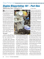
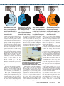
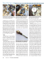
1
Technical
Engine Blueprinting 101 - Part One
Measuring Cam Timing & Lift
B
LUEPRINTING IS A time-honored
method of achieving more
power from a production
engine. Although the term is often
associated with racing, the techniques
are equally applicable to the streetbikes that you and I own.
Remember that production engines,
perhaps aside from the best superbike
motors, are not built using the greatest
care or very best machining practices,
but are objects of mass production,
subject to all manner of cost controls
and variable production tolerances.
This fact gives a careful mechanic the
opportunity to improve power significantly with relatively small expense.
The term blueprinting means to
bring all the dimensions to the ideal
numbers called out in the engine’s
blueprints, but it can also mean optimizing the range of allowable variations to achieve precisely those that
will deliver the best power.
We’ll confine our series to the top
end, and our current Project Bike,
Suzuki’s DR650SE, will be the
model, but the techniques shown
apply to virtually any engine.
The Camshaft
The business of the camshaft is to
coordinate the openings and closings of
the valves on our four-stroke engines, so
that on every second revolution, combustion occurs, creating the power that
drives our motorcycles forward.
The chant “Intake, Compression,
Power, Exhaust” that every shop student
learns by heart on the first day of class
would make you imagine that each phase
of the process takes precisely half a turn of
the crankshaft, but that’s not true. In fact,
the Intake stroke steals time from the
Compression stroke and the Exhaust
stroke steals time from the Power stroke.
The intake valve opens just before the
piston starts the downward Intake stroke,
and the exhaust valve’s closing is typically
delayed by a similar amount, to take
advantage of the gas flow inertia at work
as the engine runs. By leaving both valves
open for a moment as the piston reaches
top dead center (TDC) at the end of the
Exhaust stroke, the out-rushing exhaust
gases will tend to create a suction effect on
the intake side, initiating fuel/air flow
before the piston’s descent works to create
30
FEBRUARY 2011
●
its own pull. This phase, when both valves
are open, is called Overlap. Engines tuned
for a broad torque range and good lowspeed power, like our dual-sport, will use
a brief overlap period of perhaps 20°,
while engines designed for high-rpm
power will use from 50°–75°.
Long overlap is reserved for high-rpm
motors because at lower revs a delayed
exhaust closing will tend to backflow into
the cylinder, and hot exhaust gas will take
up significant space, making filling the
cylinder with fresh air and fuel impossible
to accomplish.
The other valve timing events are similarly adjusted to make the most efficient
use of these inertial flow effects. The
intake valve won’t close at the bottom of
the piston’s Intake stroke, which would
seemingly give the rising piston its maximum possible compression. Instead, the
engine designer will leave the valve open
much longer, abbreviating the Compression stroke, utilizing the inertia of the
intake flow to continue filling the cylinder
as the piston rises for a significant portion
MOTORCYCLE CONSUMER NEWS
by Dave Searle
of its travel. An engine designed for
strong low rpm running will have the
intake valves close about 45°–50° of
crankshaft movement after bottom
dead center (ABDC) on the Compression stroke, while a high-rpm
racing engine may keep the intake
valves open until 100° ABDC or
more. Incidentally, a high static
compression ratio is required when
the compression stroke is shortened
this way, and compression ratios are
always figured as if the intake
valve(s) close at BDC.
Of course, the same backflow situation will happen with late intake
closings at low rpm, only this time
the intake charge will reverse direction and push back out through the
carb or throttle body, reducing volumetric efficiency. This quantity of
regurgitated fuel/air mixture will
typically be contained in the airbox
so it doesn’t escape entirely, but it
will then be treated to a second shot
of fuel as it is drawn back in on
the next intake cycle, ruining its
mixture accuracy.
Exhaust timing is adjusted so that
valves will open well before the piston’s downward Power stoke ends
at bottom dead center (BDC). Again,
the engine’s intended use will determine
when, and tends to range from 45°–50°
before bottom to as much as 75° or more.
This early-opening scenario is called
“blow down” and is done in order to aid in
emptying the burnt contents of the cylinder after the combustion pressure has done
the majority of its work and before the rising piston expels the remainder. Remember that the volume of the combustion
chamber rapidly expands as the piston
descends, reducing the effective working
pressure on the crankshaft.
Aside from the timing of the valve
events, which are carved into a fixed
arrangement by the hardened steel shapes
of the cam lobes, valve lift is the other key
to camshaft performance. To see with
your own eyes how small a distance the
valve actually moves away from its seat is
to appreciate the potential for flow
increase with higher lifts. (See image)
This is a fundamentally different problem than cam timing and duration. We
would prefer to open the valves instantly
to the full height that will eliminate flow
Intake Overlap phase begins
before TDC on the Exhaust
stroke, so that negative pressure in the exhaust pipe will
initiate intake flow before the
piston’s descent creates its
own suction effect.
Compression is cut short by
extending the intake cycle to
take advantage of inertial
ramming. The compression
ratio is raised to compensate
for the degree of reduced
piston travel before closing.
Power stroke is cut short by
early opening of the exhaust
valve, after combustion pressure has done the majority of
its work. This is called “blow
down” and helps to evacuate
the cylinder of burnt gases.
the gastank, to ensure that no dirt falls
restriction between the valve and its seat,
inside the motor when the covers have
but we can’t. The lift necessary to elimibeen removed. Make sure that any pasnate any restriction is possible to achieve,
sageway into the motor is plugged with
but not instantly by any current means, so
clean rags or paper towels as you proceed.
the accelerations induced in the valve train
There’s nothing worse than multiplying
must be carefully calculated. The valves,
your efforts just to retrieve a clip or
springs, retainers and keepers plus shims,
washer that’s fallen into the bottom of the
rocker arms, clearance adjusters, pushrods
motor when it didn’t have to happen.
and lifters, if the engine has them, all have
their own inertial weight and some are
even slightly flexible in addition. The
quicker we move the valves, the stronger
the valve springs must be to control them,
and the highest rpm the engine will attain
determines the required spring pressure.
This spring force should not be taken
lightly when considering a change of
camshafts, as even in the best of circumstances, it causes friction and wear
between the lobes and lifters, which
already constitute one of the most
difficult lubrication jobs in the motor.
The DR’s intake valve at full lift. The tempOnly the desmodromic system used by
tation to increase lift for more flow is great,
Ducati escapes this conundrum.
but stronger springs may be required,
increasing friction, wear and parts expense.
Tools
On the DR, it doesn’t take much more
A factory shop manual is essential. It
than an hour to disconnect everything
will not only contain nearly all the speciattached to the top of the motor: airbox
fications you’ll need, but it will also
boot, carburetor, exhaust pipe, oil cooler,
illustrate the correct routing of all the
sparkplugs, etc. If you carefully put the
hoses and wiring you’ll disturb as you
various bolts in egg cartons from left to
disassemble the machine.
right and top to bottom, you’ll find it easy
Once again, the DR650’s big singleto reverse the sequence when it’s time to
cylinder engine makes disassembly easy
put it all back together. Take pictures of
and simplifies many subsequent operathe various hose routings with your
tions. We found the entire top-end job can
digital camera to serve as maps if your
be done without removing the motor from
service manual doesn’t detail these adethe frame. And, it’s always important to
quately. Use masking tape tags to note
begin with a clean bike, especially under
Exhaust starts early and lasts
past TDC to aid intake flow
during overlap.Too much
overlap can cause backflow
into the cylinder at lower rpm,
hurting the engine’s ability to
draw in fresh air/fuel.
which hose goes where. Rather than just
dive in, a little time spent on these details
will remove a lot of potential stress later.
It’s possible the motor will be apart for
weeks if you only have time to work on it
nights and weekends, like we did, and
it’s easy to forget details that seemed
insignificant at the time.
The DR’s cam timing is not given in
the factory service manual, but even if it
were, we’d need to verify it. Lift, overlap,
opening and closing times and lobe
centers are all important information that
provide reference points when appraising
the degree of tuning from the factory or
choosing an appropriate aftermarket cam.
Then, if you download the figures for the
possible aftermarket cams available,
you’ll be able to see how they compare to
your stocker.
Cam timing that’s off by just 2° at the
crankshaft due to manufacturing tolerances will change valve events by twice
that amount, which is very significant to
how well your motor runs. Adjustable
cam sprockets or modifications to your
stock sprockets will allow you to correct
or alter timing without buying a new cam,
but even a new cam needs to be checked
and will probably also require adjustment
to achieve the intended timing.
A minimum of special tools are necessary. You’ll need a large degree wheel
that will be attached to the end of the
crankshaft, a piston stop, a dial indicator
and a holding fixture to secure the indicator in position over the valve spring
retainers to measure movement with
crankshaft rotation.
Visit us at WWW.MCNEWS.COM
●
FEBRUARY 2011
31
Technical
Precisely set valve lash to zero beforehand in order to read cam timing and get
an accurate measurement of lift.
You can make a piston stop from an old
sparkplug held in a vise. Breaking off the
top and pounding on the center electrode
with a drift will drive the porcelain
through the middle so a length of threaded
rod can then be epoxied inside. Be careful
not to allow interference between the stop
and the valve heads or you could bend a
valve. Because the DR has a pair of sparkplug holes, we used the outermost hole to
keep a safe distance away from the valves.
The length of the stop can be estimated
with a thin screwdriver inserted in the plug
hole with the engine 10°–15° from TDC.
Degree wheels are available from all the
camshaft manufacturers and dial indicators and holding fixtures are offered on
the internet; $100 can buy all three.
The tip of the indicator must contact the
spring retainer without being hit by the
lifter over the full range of its travel.
From that point on, rotate the motor by
turning the rotor and not the degree wheel
to avoid possible misalignment. Don’t be
surprised if this is more difficult than you
imagined. Even with the sparkplugs out,
the rotor’s magnets and especially the
valve springs create significant resistance.
This can be minimized on four-valve
engines by measuring while only a single
valve operates on each side. With the
engine at TDC on the combustion stroke
Set-Up
The first step is to locate Top Dead
Center. Of course, you’ll find TDC
marked on your ignition rotor, to be lined
up with a corresponding point on the
engine case, but it can’t be trusted.
Manufacturing tolerances allow all sorts
of misalignments.
Make a sturdy pointer to serve as your
degree wheel’s reference point. We made
one from the steel rod in a pants hanger,
sharpening the end on the bench grinder.
Secure the degree wheel so that the
engine’s marked TDC corresponds to the
pointer. The piston stop is next. This will
prevent the piston from reaching the top of
the stroke so that by carefully rotating the
engine back and forth to reach the stop,
the degree wheel will show if the factory
mark is perfectly aligned. Any discrepancy will give a different number of
degrees BTDC (Before Top Dead Center)
and ATDC (After). Move the degree
wheel to split the difference and you’ve
located the true TDC point. Make sure the
degree wheel is then well tightened so that
it cannot be shifted accidentally.
32
FEBRUARY 2011
●
Home-made piston stop: Created from an
old sparkplug with a vise, hammer and
drift, with threaded rod epoxied inside.
(both valves fully closed) eliminate the
valve lash on the most accessible intake
and exhaust valves (left side on the DR).
This is easy with the DR’s screw and
locknut adjusters. Very carefully turn the
adjuster screw by hand until it just stops
and then carefully snug the locknut without moving the adjuster any further. On
the second intake valve, unscrew the
adjuster as much as possible without letting it fall out; this way it won’t compress
the valve, saving the extra effort to compress its springs. Do the same on the
exhaust side. Shim-adjusted valves in a
DOHC engine will require thicker shims
to be fitted in order to exactly zero the
MOTORCYCLE CONSUMER NEWS
With the indicator compressed enough to
record full movement and the lifter on the
cam’s base circle, zero the bezel.
lash. Pro engine builders will leave nothing to chance and measure the timing of
every single valve, to make sure that all
lobes are matched for duration, lobe
center and lift.
Position your dial indicator’s tip on the
top of the spring retainer on the valve you
are measuring, with the gauge compressed
far enough that full compression of the
valve is within its range, then rotate the
indicator’s bezel to align the zero mark
with the pointer on its face. Because a
rocker arm moves across the valve as it
compresses, you’ll find it difficult to
ensure that the rocker arm and dial indicator don’t interfere at full lift. Don’t force
anything, which could spoil the measurements and possibly damage the expensive
indicator, and check to make sure everything is good before proceeding with the
measurements. Always turn the crank in
the direction of engine rotation. If you
exceed your mark, back up a short distance
and turn forward again carefully; we don’t
want cam chain slack to alter our readings.
Get out your notebook and record the
measurements. Cam manufacturers will
typically give lifts at either .040" (equivalent to 1mm) or .050" (traditional in the
US). Be sure to record both these numbers, as well as the additional steps at .100,
.150", .200", etc. until the cam lift peaks
(record this figure, too) and then as it
returns to its seat. We’d suggest you
record the smaller numbers; the point of
initial movement and steps at finer increments like .010", .020" and .030", also.
These smaller lifts happen much more
gradually and represent the opening and
closing ramps on the cams, designed to
smoothly take up slack before moving the
valve quickly. Double check your measurements. Repeatability is your assurance
it’s correct. Keep working until you’ve
achieved this. A slightly loose holding fixture, overtightened adjuster or interfer-
opening and closing points but
expect you to determine these
numbers from the duration and lobe
center figures.
INTAKE
EXHAUST
Perhaps the most critical number
Lift
Degrees
Lift
Degrees
is intake closing as this is where true
.040"
4.5° BTDC
.040" 46.4° BBDC
cylinder compression starts. The
.050"
2°
BTDC
.050" 43° BBDC
later the intake closes ABDC, the
.100"
11.5° ATDC
.100" 28.5° BBDC
higher the rpm at which peak torque
.150"
24° ATDC
.150" 11° BBDC
will be produced. Figure that the
.200"
37° ATDC
.200" 3°
BBDC
torque peak rises roughly 100 rpm
.250"
51° ATDC
.250" 11° ABDC
later in the power curve for each
.300"
67.5° ATDC
.300" 61.5° ABDC
degree of later intake closing. For
.350"
85° BBDC
.350" 86° ABDC
instance: Do you want more low.361" 73° BBDC
.363" 84° BTDC
rpm power than stock? Advance the
cam. Do you want the same low rpm
.350"
51° BBDC
.350" 86° BTDC
torque as stock? If so, choose a cam
.300"
24° BBDC
.300" 61.5° BTDC
that has nearly the same intake clos.250"
8.5° BBDC
.250" 45° BTDC
ing as stock. Would you like the
ABDC
.200" 30.5° BTDC
.200"
7°
maximum torque 500 rpm later than
.150"
19° ABDC
.150" 18°
BTDC
stock? Choose one with the intake
.100" 31° ABDC
.100" 5°
BTDC
closing roughly 5° later.
.050" 45° ABDC
.050" 9°
ATDC
Lift is obvious. More is typically
.040" 48° ABDC
.040" 12.5° ATDC
better, but to get much more, other
changes will usually need to be
Intake Duration:
Exhaust Duration:
made. The stock valve springs may
@ .040" lift = 232.5°
@ .040" lift = 239°
not be strong enough to control the
valve accelerations at high speed if
@ .050" lift = 227°
@ .050" lift = 232°
Lobe Center = 111.5°
Lobe Center = 107° the lift is much higher. Your cam
maker will usually recommend the
necessary springs. The stock valveIf stock cam is advanced 4° (@ .040" lift)
Intake opens @ 8.5° BTDC, closes @ 44° ABDC to-piston clearance may also be
Exhaust opens @ 44.4° ATDC, closes @ 8.5° ATDC inadequate if much higher lift is
used. The time-honored method of
checking this is to “clay” the clearATDC (After Top Dead Center)
ance. You must reassemble the cam
BTDC (Before Top Dead Center)
and top end, placing pieces of modBBDC (Before Bottom Dead Center)
eling clay (lightly oiled on both
ABDC (After Bottom Dead Center)
sides) in the piston’s valve cutouts,
turn the engine over, remove the
head, carefully slice through and
ence in the indicator’s movement will remove half the clay and measure the
thickness. But if you are careful with a digthrow off the measurements.
With this done, several important figures ital caliper, you can check clearance withwill be known: Lift, duration and lobe cen- out a mock-up assembly and disassembly.
ters. Lift is self-explanatory. Duration is A minimum of additional clearance is necthe time in degrees of crankshaft rotation essary, the precise amount dependent on
that the valves are open (given from either the size of the motor and the rpm anticithe .040" or .050" lift points). Higher lift pated (as much as .080" on big exhausts
and longer duration with different cams are and up to .100" inch for big intakes) Natthe time-honored ways to add flow capabil- urally the costs of special valve springs
ity. The “lobe center” numbers are meant to will need to be calculated (about $200 per
be an easy way to visualize the alignment four-valve cylinder) and located as well as
point of maximum lift, given in degrees, the expense of piston valve pocket machineither BTDC (for exhaust cams) or ATDC ing if you get greedy with lift. But, as our
(for intake cams). For intake cams, you focus is optimizing the stock engine, we
divide the duration in half and subtract the don’t have to worry about that.
number of degrees the cam opens before
TDC during the overlap phase. For exhaust What We Found
cams, divide duration in half and subtract
As expected, the stock cam is biased
the number of degrees the cam is kept open toward the lower end of the rpm range;
after TDC during overlap.
good for dual-sport and off-road use.
With these numbers, it’s easy to com- Supermoto applications would suggest a
pare your stock and aftermarket cams. Note new cam that raises the torque peak
that aftermarket cams do not specify the maybe 500 rpm; road racing perhaps even
DR650SE
more. Engine tuning is about compromise; giving up something to get something more in a different place. Analyze
your favorite type of riding. What would
be ideal?
In fact, we learned our DR’s cam timing
is retarded by 4° from the common “split”
overlap, the intake lobe center at 111.5°
ATDC and the exhaust lobe center at 107°
ATDC. Such retarded timing is unusual,
and evenly split or advanced timing should
improve performance, adding effective
compression, low-speed power and reducing the tendency for back flow on the intake
and exhaust. Although dyno tuning is
required to optimize the exact timing figures, we feel comfortable advancing the
stock cam timing by 4° to achieve split
overlap, which we will cover in Part Four
of this series, when we reassemble the
motor after verifying and correcting the
actual compression ratio in Part Two and
cleaning up the ports and machining the
valve seats in Part Three.
Comparing our stock cam with the most
popular aftermarket alternative was also
illuminating. The new cam’s timing was
almost identical and the new cam’s lift was
actually less. Although we’d really need to
know all the lift/degree figures to be
absolutely sure (which are not normally
divulged by cam manufacturers), the comparison suggests we’d be wasting our
money if we hoped for more power (and
dyno tests by other tuners using this cam
back up our numerical analysis).
The surprises continue in Part Two, so
stay tuned, we think you’ll enjoy the trip.
RESOURCES
Reading: Four-Stroke Performance
Tuning by A. Graham Bell. 3rd Edition
by Haynes Publishing. Probably the
best single reference book on the subject. Highly recommended. Hardcover
$60.98, available from Amazon.com for
$23.94, or even less in used condition.
Degree wheel: Competition Cams 7.5"
Sportsman wheel, Part # COC-4787.
$14.25 from www.888murrays.com
Central Tools 1"-travel dial indicator
with magnetic holding fixture. Mfg #
3D102. Model # 112202, $71.20 from
www.toolsource.com.
Cam degreeing kit (everything needed)
with video. Web Cam # AP-144, $265.
Web is also a good source for instructional info. www.webcamshafts.com
Visit us at WWW.MCNEWS.COM
●
FEBRUARY 2011
33


![United StiltBS Patent [19] [11] Patent Number: 5,025,556](http://vs1.manualzilla.com/store/data/006008181_1-2c5f49b6565f7d3a6ea1501cb683eb1f-150x150.png)