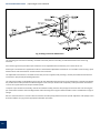
1
Issue 2010
User Manual
Clearscan Chart Recorders
Installation, Setup, Operation & Calibration
With over seventy five years of experience, British Rototherm continues to be a world leader in the manufacture of
industrial instrumentation for measuring, monitoring and controlling Temperature, Pressure, Humidity, Flow and
Level.
British Rototherm products are manufactured in its modern factory located in the South Wales region of the United
Kingdom. Sited on 6 acres of land at Kenfig Industrial Estate, the company operates from a modern 6,030 square
metre (65,000 square feet) factory.
Suitable for many industrial applications, Rototherm products are precision built to the highest quality.
Approved by major companies and contractors in the United Kingdom and throughout the world for the supply of
instrumentation and associated products, Rototherm products are specified and installed wherever reliability and
long lasting, accurate performance is demanded.
Rototherm’s high quality and performance is guaranteed by an uncompromising approach to quality.
Rototherm is supported throughout the United Kingdom by Technical Representatives and by distributor/Stockists,
who can be relied upon for support, technical advice and service.
Rototherm also has representation in many countries throughout the world where technical support and advice may
be sought.
Other products in the Rototherm range of instrumentation include:
•
•
•
•
•
•
•
•
•
•
Mechanical Recorders & Recorder Controllers
Pneumatic Indicators & Recorder Controllers
Thermometers
Digital Thermometers
Pressure Gauges
Digital Pressure Gauges
Thermowells
Temperature Sensors & Assemblies
Orifice & Restriction Orifice Plates
Recorder Charts, Pens & Spares
British Rototherm Company Limited
Kenfig Industrial Estate, Margam, Port Talbot, SA13 2PW United Kingdom
Telephone: +44 (0) 1656 740 551
Facsimile: +44 (0) 1656 745 915
E-mail: [email protected] Web Site: www.rototherm.co.uk
TM
ISO9001:2008
In keeping with British Rototherm’s policy for contuned product development and improvement, we reserve the right to amend specifications without notice.
©2010 British Rototherm Co. Ltd. All rights reserved.
Trademarks: All brand names and product names used in this manual are trade names, service marks, trademarks or registered trademarks of their respective owners.
Clearscan Recorder Series | Operating & Service Manual
CONTENTS
Introduction
2
Description of Operation of Gas Pressure Recorder
2
Description of Operation of Temperature Recorder
2
Description of Operation of Differential Pressure Recorder
2
Receipt of Recorder
3
Receipt of Temperature Recorder
3
Installation and Mounting - wall or panel mounting
3
Installation and Mounting - 2” pipe or post mounting
4
Installation and Mounting - Differential Pressure Recorder complete with 2” pipe or post mounting
5
Process Connections - Pressure
6
Process Connections - Temperature
6
Process Connections - Differential Pressure Recorder
7
Access to the Recorder
7
Internal Features
8
Recorder Start-up Check
8
Differential Pressure Recorder Initial Start-up
9
Differential Pressure Recorder General Practices
9
Fitting a Chart
9
Inking System
9
Replacement of Ink Pens
10
Pen Friction and Zero Adjustment
10
Tracking Adjustment to Chart Time Line
11
Chart Drives
11
Linkage and Pivot Attachments
11
Basic Fault Finding
13
Temperature Pen Calibration
18
Pressure Pen Calibration - for pressure ranges 2.5 bar to 40 bar
19
Pressure Pen Calibration - for pressure ranges 60 bar and above
19
Maintenance and Calibration - Differential Pressure Recorder
21
Calibration of Differential Pressure Pen
21
Spares List
23
Illustrations
Fig. 1a Outline Dimensions for 12 inch chart recorder (wall or panel mounting)
3
Fig. 1b Outline Dimensions for 12 inch chart recorder (2” pipe / post mounting)
4
Fig. 1c Outline Dimensions for 12 inch chart recorder (fitted with Differential Pressure Unit)
5
Fig. 1b Wall mounting dimensions using optional wall bracket kit
5
Fig. 2 Internal Features (with chart plate in place)
8
Fig. 3 Measuring and recording system details
10
Fig. 4 Linkage and pivot attachments
12
Fig. 5a Temperature recorder internal layout
14
Fig. 5b Pressure recorder internal layout (pressure ranges up to 40 bar)
15
Fig. 5c Pressure recorder internal layout (pressure ranges 60 bar and above)
16
Fig. 5d Differential pressure recorder internal layout
17
Fig. 6 Typical pressure calibration setup
20
1
Clearscan Recorder Series | Operating & Service Manual
INTRODUCTION
The Clearscan™ Series of circular chart recorders is designed to measure and record process variables such as temperature, pressure and flow.
A maximum of three measuring systems can be provided in each instrument, a fluid or gas expansion system is used for temperature recording, a bourdon tube or diaphragm/capsule for pressure measurement and a differential pressure cell for flow reading.
The measured values are continuously recorded on a calibrated circular chart of 12 inches nominal diameter, which is
rotated at a constant speed by a chart drive mechanism.
DESCRIPTION OF OPERATION OF GAS PRESSURE RECORDER
On medium and high-pressure ranges, (i.e. approx. 2.5 bar to 2000 bar) pressure is applied at the recorder connection through
capillary tubing to a spiral wound bourdon tube.
An increase in pressure partially uncoils the bourdon tube to which is fitted a take-off assembly arm converting the rotational
movement into linear movement.
A horizontal adjustable linkage is pivoted from the take-off arm to a pen mechanism bracket, incorporating a pivot mounted onto
an adjustable ratio post, locked into position on the pen bracket.
The ratio post provides span adjustment; it’s position setting the pivot distance of the centre of rotation of the pen arm itself.
Adjusting the ratio post upwards nearer the centre of rotation increases the pen travel whilst conversely adjusting the ratio post
downwards will result in less travel of the pen for the same amount of deflection from the bourdon tube
take-off arm.
The top of the pen bracket carries the pen arm mounted onto a separate adjustment plate which provides fine zero adjustment
at the pen nib and adjustment to the amount of tension on the pen arm itself; thereby ensuring a smooth pen trace
onto the chart paper.
The pen attached to the pen arm records the pressure on a calibrated chart.
A capsule stack is fitted for low-pressure ranges (i.e. below 2.5 bar) and the expansion of the system resulting from an increase in
pressure is transferred by mechanical linkage to the pen arm in a similar way.
DESCRIPTION OF OPERATION OF TEMPERATURE RECORDER
As temperature rises, the fluid/gas in the thermometer bulb expands and partially uncoils the bourdon tube fitted inside the
instrument.
This movement is transferred by a mechanical linkage to the pen arm which records the temperature on a calibrated chart.
The instrument is suitably compensated against normal ambient temperature variations by a bimetallic compensator arm forming part of the mechanical linkage.
DESCRIPTION OF OPERATION OF DIFFERENTIAL PRESSURE RECORDER
Differential pressure (produced by an orifice plate, Dall tube, Venturi or Pitot tube etc..) is measured by a bellows operated Differential Pressure Unit (DPU) mounted at the rear of the recorder.
The axial movement of the bellows is transferred by a torque tube within the unit to produce a rotational output which is transferred by mechanical linkage to the recording pen.
The measured value of differential pressure is displayed in red trace on a circular chart which is rotated at a constant speed by a
mechanical, battery or electrical chart drive motor.
2
Clearscan Recorder Series | Operating & Service Manual
RECEIPT OF RECORDER
The Clearscan recorder complete with a packet of charts, door keys and pen pack(s) is dispatched in a protective casing which
should preferably be replaced after inspection, as protection until the instrument is ready for installation.
The spare pen pack(s) and door keys are inside the protective case.
To assist with inspection, a label attached on the inside face of the case door states instrument serial number, chart number,
range of each pen and the rotation speed of the chart drive.
Additional parts for pipe mounting versions are packed in the protective casing during transit.
RECEIPT OF TEMPERATURE RECORDER
The capillary tubing between the bulb and recorder is coiled for despatch purpose. Immediately prior to installation, this tubing
must be uncoiled carefully in order to avoid twisting or kinking.
INSTALLATION AND MOUNTING - wall or panel mounting
Ideally the site chosen should be free from dust, corrosive fumes, vibration and extremes of temperature.
The instrument is suitably designed for outdoor weather conditions and protected against ingress of dust and water.
The recorder is suitable for wall or panel mounting using the brackets provided.
Refer to figure 1 for overall dimensions of the recorder and general installation.
All dimensions are in mm
371
41
114
312
483
490
56
PRESSURE CONNECTION
1/2" NPT STANDARD
OR 1/4" NPT OPTIONAL
WALL MOUNTING
420
53
302
327
CASE BREATHER
PANEL CUTOUT SIZE: 305 x 425
PANEL MOUNTING
Fig. 1a Outline Dimensions for 12 inch chart recorder (wall or panel mounting)
3
Clearscan Recorder Series | Operating & Service Manual
INSTALLATION AND MOUNTING - 2” pipe or post mounting
Ideally the site chosen should be free from dust, corrosive fumes, vibration and extremes of temperature.
The instrument is suitably designed for outdoor weather conditions and protected against ingress of dust and water.
The recorder is suitable for mounting onto either a vertical or horizontal 60mm outside diameter post or pipe having a 2” nominal bore using the ‘U’ bolts provided.
Refer to figure 1 for overall dimensions of the recorder and general installation.
The post or pipe may be vertical or horizontal to the recorder but the recorder must be installed vertically.
All dimensions are in mm
371
41
114
4
60mm O/D PIPE OR POST
490
65
56
420
483
53
PRESSURE CONNECTION
1/2" NPT STANDARD
116
6
302
CASE BREATHER
Fig. 1b Outline Dimensions for 12 inch chart recorder (2” pipe / post mounting)
4
Clearscan Recorder Series | Operating & Service Manual
INSTALLATION AND MOUNTING - Differential Pressure Recorder complete with 2” pipe/
post or wall mounting
All dimensions are in mm
305
371
41
83
114
30
DIFFERENTIAL
PRESSURE
UNIT
BLEED VALVE
90
490
51
420
61
LOW PRESSURE
CONNECTION
1/4” NPTF
180
HIGH PRESSURE
CONNECTION
1/4” NPTF
60mm O/D PIPE OR POST
TEMPERATURE
SYSTEM
CONNECTION
53
STATIC PRESSURE
CONNECTION 1/4” NPTF
302
Fig. 1c Outline Dimensions for 12 inch chart recorder (fitted with Differential Pressure Unit)
All dimensions are in mm
60mm O.D. PIPE
TO MOUNT RECORDER
165
135
50
60mm O.D. PIPE
TO MOUNT RECORDER
60
4 x 12 DIA. FIXING HOLES
ON 50 x 72 CENTRES
4 x 12 DIA. FIXING HOLES
ON 135 x 72 CENTRES
Fig. 1d Wall Mounting Dimensions using optional wall bracket kit
5
Clearscan Recorder Series | Operating & Service Manual
PROCESS CONNECTIONS - Pressure
To avoid confusion on instruments fitted with more than one measuring system, the connections are marked with the same
colour as the corresponding recording pen colour.
The recorder is fitted with NPT threaded connection(s) and all pipelines attached to it must be secure and leak proof. PTFE sealing tape must be used to make a pressure tight join to the recorder connections.
Use pressure tubing of sufficient size and rating to make a connection from the measuring point in the flow pipe or vessel to the
fitting(s) on the recorder.
Slope the run of the pipe-work in such a way that any condensate is drained away from the recorder, and fit an appropriate shutoff valve. For measurement of steam pressure and other hot vapours, form a condensate trap below the recorder.
It is recommended that a needle valve be installed in the pressure line close to the instrument to enable pressure to be admitted
gradually. It can also dampen any pressure pulsation and/or fluctuation.
PROCESS CONNECTIONS - Temperature
Capillary tubing: The tubing between the bulb and recorder should be routed so that it is not subjected to large temperature
changes and should be supported in cleats. Bends must not be less than 25mm (1inch) radius and under no circumstances must
the tubing be cut.
Where the tubing is likely to be exposed to an extreme atmosphere, the exterior should be treated with corrosion resistant paint.
Location of Bulb (Detecting Element):
Immersion type bulb
The instrument bulb should be located where it is subject to the true temperature of the measured medium. Temperature gradient within the medium must be allowed for, and with bulbs allowing variable depth of immersion (compression gland type), the
bulb position should be varied experimentally until the optimum position is found.
The full length of the sensitive portion must at all time be immersed in the medium, but direct contact with the source of heat to
the medium must be avoided.
When securing the bulb in its location, it should be prevented from twisting.
Where a pocket is supplied, this should be securely installed before the bulb is inserted. It may be that the thermal response of a
pocketed bulb is improved by filling the intervening space with a medium such as oil.
General Maintenance
6
• keep the instrument clean and treat with care
• where there is a risk of corrosion the bulb should be inspected periodically
• if corrosion is evident, it should be removed by non-abrasive treatment
• any contamination on the bulb should be removed
Clearscan Recorder Series | Operating & Service Manual
PROCESS CONNECTIONS - Differential Pressure Recorder
The ¼-inch-18 NPT piping connections of the differential pressure unit when viewed from the rear of the recorder are as
follows:
High pressure on the right hand side marked +
Low pressure on the left hand side marked The following practices should be followed on all flow and liquid level DPU piping.
1. The distance between the primary device and the DPU should be as short as possible. Distances exceeding 100 feet are not recommended. For distances up-to 15 metres (50 feet) use ¼-inch or 3/8-inch pipe or tubing. For runs of 15 to 30
metres (50 to 100 feet) use ½-inch pipe or tubing. This recommended distance limitation does not apply if an air-purge
or blow system is used.
2. Slope all piping at least 25mm per linear 305mm (1-inch per linear foot) to avoid liquid or gas entrapment.
3. If process media exceeding 93°C (200°F) is to be measured provide two feet of un-insulated piping between the
primary device and the DPU for each 38°C (100°F) in excess of 93°C (200°F).
4. When steam tracing is necessary, the steam pressure should not exceed 35kPa (5 psi) and insulation should not be used.
If pressure above 35kPa (5 psi) is required, limit the length of tubing around the DPU to two turns and do not insulate.
The temperature of the DPU must never exceed 93°C (200°F).
5. Severe pulsation will affect the accuracy of the instrument. The installation of a pulsation dampening device upstream
of the run is recommended when flow is being measured.
6. Minimise vibration by mounting the instrument on a secure support.
7. Measurement errors can be caused by leaks in the pipe joint; make up all joints using a suitable pipe joining compound
8. The DPU has two pressure connections in each housing for easy connection to the differential pressure source with a
manifold to facilitate operation and checking.
9. Locate shut-off and by-pass valves easily accessible to operator from the front of the instrument. The block valve should
be the first valve from the process line or vessel.
ACCESS TO THE RECORDER
To open the door, unlock the door lock by inserting the key and turning clockwise a half turn.
To open the door, rotate the wing handle of the door lock a quarter turn anticlockwise.
7
Clearscan Recorder Series | Operating & Service Manual
INTERNAL FEATURES
Blue
Fig. 2 Internal Features (with chart plate in place)
RECORDER START-UP CHECK
Before putting the recorder into operation make the following checks to ascertain that it is correctly installed and
operational.
8
1. Remove the elastic band securing the pens to the steel pen lifter arm for despatch purposes.
2. The pen(s) operate freely, write clearly on the chart and pass each other without touching.
3. Measuring elements are correctly installed.
4. Measuring elements are indicating correctly. If not, refer to zero adjustment.
5. Ensure that, in case of instruments fitted with mechanical chart drive, it is running.
6. Fit a new chart with its edge under the guide clips, set it to the correct time line and clamp the centre-fixing device.
Clearscan Recorder Series | Operating & Service Manual
DIFFERENTIAL PRESSURE UNIT (DPU) RECORDER INITIAL START-UP
Due to possible periods of storage prior to installation, the DPU bellows may take a “set”. Therefore, it is recommended that the
first time the DPU is used, and prior to actual operation, the instrument be exercised to ensure correct operation. To exercise the
DPU, apply maximum and minimum pressure to the high pressure side for at least ten cycles.
DIFFERENTIAL PRESSURE UNIT RECORDER GENERAL PRACTICES
Observe the following practices when starting operation of the instrument:
1. Always start with the block valves closed.
2. Perform a zero check of the instrument by equalising the pressure to both sides of the DPU and if necessary zero the
pen to the correct chart reading.
3. Check manifold and piping for any leaks.
4. Do not subject the DPU to unnecessary pressure shock or over-range during start-up.
FITTING A CHART
Clearscan charts are 12” (300mm) nominal diameter printed on to temperature and humidity stable 7-point paper.
Mechanical Clock (Note: clocks up to 24 hour rotation have combined chart clamp winder, rotations above 24 hour have a separate clamp and winder).
Release the chart clamp as follows (please refer to the chart drive section for information on other chart drive types):
1. Unscrew to remove the winder clamp from the clock hub
2. Operate the pen lifter to raise the pen arm(s)
3. Slide the chart under the pen lifter and pen arm(s) and locate the chart centre hole over the clock hub
4. Place the chart beneath the outer chart clips.
5. Align the red pen with the correct timeline on the chart. On a two-pen instrument the blue pen will be 4mm in advance
of the red pen.
6. Refit the winder clamp.
INKING SYSTEM
The writing system uses fibre tip pen capsules.
Where there are two or more measuring systems, different colour inks are used to distinguish the traces.
The fibre tip is protected by a rubber cap, which should be removed by pulling in line with its length, gripping the end only and
gently twisting.
The capsule accepts the steel pen arm and a clamp provided on the capsule to secure itself to the pen arm.
The first pen is coloured red, whilst the second pen is blue.
9
Clearscan Recorder Series | Operating & Service Manual
REPLACEMENT OF INK PENS
Ink capsules can be easily replaced when the ink is exhausted.
To fit a new pen capsule:
1. Operate the pen lifter by hand by removing it from under the catch post attached to the case wall on the inner left-hand
side. This will raise all pens away from the chart paper.
2. Un-clip the moulded clamp on the pen capsule; remove the existing capsule by pulling carefully upwards and outwards
from pen arm.
3. Place a new capsule onto the pen arm ensuring the end of the pen arm is correctly position to the pen stops, secure the
capsule in place with the clamp provided.
4. Remove the pen nib cover.
5. Reposition the pens onto the chart paper by lowering the pen lifter and retain it under the catch post attached to the
case wall on the inner left-hand side.
PEN FRICTION AND ZERO ADJUSTMENT
Each recording pen is fitted with screws for friction and zero adjustment.
These adjustments are factory set to optimal setting, however various plant conditions and usage may result in the need to make
minor changes for correct operation.
The pen trace can be altered to optimum by turning the pen arm friction adjust screw provided bearing onto the pen arm as
shown in figure 4.
To bold-en the pen trace gently turn the screw clockwise, to lighten gently turn the screw anti-clockwise.
To position the pen to read accurately at zero when pressure is vented or any desired known pressure value on the chart, turn
the pen arm fine zero adjust screw in the direction required to move the pen the desired amount.
If for any reason, the required pen zero adjustment is more than a small increment, refer to detailed maintenance notes
especially if the calibration accuracy of the recorder is suspected of inaccuracy or is impaired.
BOURDON TUBE
SHOULDER SCREW
LINK SCREWS
PEN STOP
RATIO POST
SPAN ADJUST
PEN ARM
CLAMP SCREW
BOURDON CENTRE SCREW FIXING TAKE-OFF
ASSEMBLY TO BOURDON TUBE
HORIZONTAL LINK
ZERO ADJUST
PEN ARM FINE ZERO ADJUST
PEN ARM FRICTION ADJUST SCREW
TAKE-OFF ASSEMBLY
PEN ARM
10
Fig. 3 Measuring and recording system details
Clearscan Recorder Series | Operating & Service Manual
TRACKING ADJUSTMENT TO CHART TIME LINE
To adjust the pen arm arc length to accurately track the chart time line, gently slacken the two pen arm clamp screws shown in
Fig. 4 and increase or decrease the pen length by sliding the metal pen arm in or out until the pen records along the chart time
line across the whole of the chart scale length. Re-tighten the two clamp screws. Note the red pen only must track the chart time
line, other pens fitted must be set to clear each and one another.
CHART DRIVES
The chart paper, mounted on a clamping hub, is driven by a chart drive mechanism.
Depending on requirement the chart drive will be a mechanical spring wound , battery operated or electrically powered mechanism.
Mechanical spring wound versions employ a chart paper clamp and winder hub which must be sufficiently wound by hand but
must not be over-wound.
Electric synchronous motor versions must be powered by mains supply and connections are made to a terminal block mounted
inside the recorder beneath the chart plate.
Access to the terminal block is gained by removing the chart plate, and mains supply cable is to be fitted through the cable gland
provided in the lower case wall.
For instruments fitted with mains supply chart drive motor, the mains must be switched
off before making any mechanical adjustments or carrying out any
maintenance or fault finding procedures.
It is important to properly select and connect the supply voltage. The live line should be switched and fused with a 2 Amp fuse.
The supply should be earthed and connected to the appropriate terminal within the recorder.
The chart drive hub employs a lever clamp which must be pressed firm enough to ensure the two locating pips pierce the chart
paper.
Battery Operated versions are powered by a single AA (LR6) alkaline battery fitted into a compartment mounted onto the chart
plate.
To fit a battery, first open the compartment by turning the cap counter-clockwise using a flat blade or coin. Insert the battery so
the positive terminal is uppermost.
Replace the cap, and lock by turning the cap clockwise with a flat blade or coin to its stop.
The chart drive hub is a sliding clamp type which must be pressed slightly firm to clamp the chart paper.
To remove the chart plate entirely from instruments fitted with battery operated chart drives, a separable connector is fitted to
the leads between the battery compartment and the chart drive itself.
To disconnect, pull apart the connector housings only, do not pull the wires or damage will occur. To replace, plug the housings
together and push until fitted correctly, the housings can be fitted one way only.
LINKAGE AND PIVOT ATTACHMENTS
The instrument employs similar linkage attachment whether the measuring system is temperature, pressure or differential
pressure.
The diagram and glossary on the following pages is provided to supplement the figures presented throughout this manual to
show the terminology and correct arrangement to ensure friction free linkage movement and therefore accurate pen traces.
11
Clearscan Recorder Series | Operating & Service Manual
Fig. 4 Linkage and Pivot Attachments
The recording pen mechanism assembly, mounted to the base plate via a bracket, provides attachment to the measuring
elements.
Each measuring element provides output movement via an adjustable take-off assembly arm or direct drive arm.
Either type is terminated in a tapped hole to which is attached the adjustable horizontal link via a shoulder screw forming a pivot
without excess side movement for smooth friction free movement.
The adjustable horizontal link is screwed into the ratio post at its opposite end providing a smooth pivot without excessive free
movement or play thereby eliminating hysteresis.
The ratio post provides an adjustable point of pivot for the adjustable horizontal link and span adjustment is thereby provided by
the position of the ratio post which is fitted through the slot in the pen bracket and clamped by a ratio post washer and locknut
in terms of its pivot distance to the pen bracket spindle.
To replace a pen mechanism assembly, remove the shoulder screw(s) from the ratio post(s) and undo the two nuts securing the
pen mechanism bracket to the mounting bracket. Retain all fixings ensuring the relative shoulder screw is mated with its original
linkage.
Mount a new mechanism in reverse order and measure the ratio post(s) distance from the spindle. Adjust the ratio post(s) to this
dimension before carrying out the appropriate calibration procedure.
12
Clearscan Recorder Series | Operating & Service Manual
BASIC FAULT FINDING
Recorder pen inaccurate or gives no indication
Probable cause Action Measuring element broken, pressure line plugged or broken.
Check element / pressure line; replace system if necessary.
Probable cause Action Damaged linkage in recorder.
Repair and re-connect if possible; replace if necessary.
Probable cause Action Recorder out of calibration; measuring element damaged.
Set-up and recalibrate; replace system if necessary.
No record or poor trace on chart
Probable cause Action Pen not inking.
Fit new pen capsule.
Probable cause Action Pen friction insufficient.
Adjust pen friction.
Chart not rotating
Probable cause Action Clock unwound.
Rewind, replace if broken.
Probable cause Action Clock over-wound.
Replace clock.
Probable case
Action Chart not clamped / retained on drive mechanism
Confirm knob is tightened / chart pierced and camped.
After carrying out the basic fault finding if the problem is still evident, refer to the detailed maintenance procedures or contact
British Rototherm or your local authorised British Rototherm distributor for spares, information and technical advice and
support.
13
Clearscan Recorder Series | Operating & Service Manual
TEMPERATURE BOURDON
COARSE ZERO ADJUSTMENT SCREW
COMPENSATOR ARM
RATIO POST
(UNDERNEATH
PEN ARM)
LINEARITY LINK
CATCH POST
PENLIFTER
CHART DRIVE
CHART PLATE
(PARTIALLY
REMOVED)
CAPILLARY
OUTLET PLATE
CAPILLARY TUBING
14
Fig. 5a Temperature Recorder Internal Layout
SENSING BULB
Clearscan Recorder Series | Operating & Service Manual
BOURDON TUBE
CENTRE SCREW TO
REMAIN FIXED
TAKE OFF ASSEMBLY
ZERO
ADJUST
SCREW
LINEARITY LINK
CATCH POST
PEN LIFTER
CHART DRIVE
CHART PLATE
(PARTIALLY REMOVED)
CAPILLARY
OUTLET PLATE
PRESSURE CONNECTION
Fig. 5b Pressure Recorder Internal Layout (ranges up to 40 bar)
15
Clearscan Recorder Series | Operating & Service Manual
ADJUSTABLE HORIZONTAL LINK
DRIVE ARM
CATCH POST
COIL LEVER SCREW
COARSE ZERO ADJUST
BOURDON TUBE
PENLIFTER
CHART DRIVE
CHART PLATE
(PARTIALLY
REMOVED)
CAPILLARY
OUTLET PLATE
PRESSURE CONNECTION
16
Fig. 5c Pressure Recorder Internal Layout (ranges 60 bar and above)
Clearscan Recorder Series | Operating & Service Manual
RANGE ADJUST RATIO POST
BENEATH PEN ARM
HORIZONTAL ADJUSTABLE LINK
ZERO
ADJUST
SCREW
TAKE OFF
ASSEMBLY
PEN STOP
FLANGED
BEARING
CALIBRATION CHART
SHAPE
0% INDICATION
CHART TIME LINE
50% INDICATION
CHART DRIVE HUB
SHOWN LOCKED
100% INDICATION
Fig. 5d Differential Pressure Recorder Internal Layout
17
Clearscan Recorder Series | Operating & Service Manual
TEMPERATURE PEN CALIBRATION
Mechanical calibration is concerned with the accurate setting of zero, span and linearity of the recording pen in comparison
with a known temperature read with a certified thermometer traceable to national calibration standards.
The adjustments detailed below must be performed in the order listed and the instrument must be allowed to settle before
readings and adjustments are made.
Unless a replacement mechanism assembly, temperature system or mechanical linkage is to be fitted it should not be
necessary to make coarse or linearity adjustments.
If it is not possible to achieve one or more of the following settings, contact your nearest Rototherm Distributor or the
company itself.
18
1. Allow the recorder to stabilise with the measuring element in a low temperature just above scale minimum.
2. The temperature recording pen should read within ±1% of full span at the correct temperature value.
3. If necessary, adjust pen fine zero adjust screw to bring the pen to the correct reading.
4. If the pen reading is significantly out i.e. more than 5 angular degrees, adjust the pen fine zero screw to bring the pen
arm in-line with the pen arm bracket and loosen the coarse zero adjustment screw holding the compensator arm to the
temperature bourdon tube centre. Adjust the pen to record true value, making a fine adjustment on pen fine zero
adjustment screw after the coarse zero adjustment screw has been re-tightened.
5. Allow the recorder to stabilise with the measuring element in high temperature just under scale maximum.
6. The temperature recording pen should read within ±1% of full span at the correct temperature value.
7. If necessary, adjust the pen reading by moving the link connecting the compensator arm to the ratio post on the
mechanism pen bracket.
8. In order to move the link, slightly loosen the locknut of the ratio post and by raising the pivot will increase the pen
movement whilst lowering the pivot will decrease the pen movement. Re-tighten the lock nut after adjustment.
9. Repeat steps 1 to 8 until no further adjustment is necessary.
10. Allow the recorder to stabilise with the measuring element in temperature equal to middle of chart span.
11. The temperature recording pen should read within ±1% of full span at the correct temperature value.
12. If necessary, adjust the pen linearity by loosening the coarse zero adjustment screw holding the compensator arm to the
temperature bourdon tube centre and moving the pen upwards if the reading is low and downwards if the reading is
high by a factor of 8 times greater than the reading error. Re-tighten the coarse zero adjustment screw.
13. To return the pen reading to the correct chart reading, adjust the linkage length between the compensator arm and the
ratio post pivot by loosening the two locking screws and sliding the links until the pen reads correctly.
Re-tighten the two screws.
14. Repeat steps 1 to 8 to check zero and span readings and steps 10 to 13 until all readings are correct to within ±1% of
span at measured values.
Clearscan Recorder Series | Operating & Service Manual
PRESSURE PEN CALIBRATION for pressure ranges 2.5 bar to 40 bar
Mechanical calibration is concerned with the accurate setting of zero, span and linearity of the recording pen. The adjustments
detailed below must be performed in the order listed.
Unless a replacement mechanism assembly, bourdon or mechanical linkage is to be fitted it should not be necessary to make
coarse or linearity adjustments.
If it is not found possible to achieve one or more of the following settings, contact your nearest Rototherm Distributor or the
company itself.
1. Connect a suitable pressure regulator and calibrated test gauge to instrument pressure line.
2. Ensure all linkages are free to pivot and pens align and pass each other.
3. Fit a dummy chart plate and correct chart.
4. Radial red pen arm to ensure that pen nib tracks on chart time line.
5. Set pen to read zero on chart. Ensure pen zero adjust plate lies in-line with pen arm. Make small zero adjustment
using pressure take-off assembly on bourdon. Make large adjustments using horizontal link from pressure take-off
assembly to pen mechanism.
6. Overload the bourdon tube by 15% of the maximum pressure range before staring to calibrate and check for any leaks.
Release pressure.
7. Adjust the pressure so test gauge reads maximum pressure of the instrument range. If the recorder pen does not read
within ±1% full scale deflection of this maximum value, adjust the ratio post on the pen bracket upwards to increase the scale length; downwards to reduce the scale length. Ensure to slacken and re-tighten the ratio post-locking nut during
any adjustment.
8. When the instrument is reading within tolerance for both minimum and maximum scale values adjust the pressure to
exactly half that of the pressure range of the instrument being calibrated.
9. Check the recorder accuracy is within ±1% full-scale deflection at this mid-point. If the instrument is reading low the
take-off assembly should be moved to the left by unlocking the centre fixing screw. If the instrument is reading high at
mid-point the take-off assembly should be moved to the right. Re-tighten the bourdon centre screw; adjust the
horizontal link to reposition the pen to mid-point and repeat steps 6 and 7.
10. When the instrument is reading correctly at all points make sure all links and screws are tight. Remove dummy chart
plate and replace with original.
11. Check calibration with recorder completely re-assembled before removing test gauge.
PRESSURE PEN CALIBRATION for pressure ranges 60 bar and above
1. Connect a suitable pressure regulator and calibrated test gauge to instrument pressure line or a certified dead-weight
tester
2. Ensure all linkages are free to pivot and pens align and pass each other.
3. Fit a dummy chart plate and correct chart.
4. Radial red pen arm to ensure that pen nib tracks on chart time line.
5. Set pen to read zero on chart. Ensure pen zero adjust plate lies in-line with pen arm. Make small zero adjustment
using pressure take-off assembly on bourdon. Make large adjustments using horizontal link from pressure take-off
assembly to pen mechanism.
6. Overload the bourdon tube by 15% of the maximum pressure range before staring to calibrate and check for any leaks.
Release pressure.
19
Clearscan Recorder Series | Operating & Service Manual
20
7. Apply 50% full rated pressure of the bourdon and set the coil lever to be absolutely vertical by loosening the coil lever
clamp screw and moving the coil lever appropriately. Re-tighten the clamp screw.
8. Adjust the length of the horizontal link if necessary to make the pen read on the mid scale line of the chart at 50% full
rated pressure. Re-tighten the linkage screws.
9. Release pressure to zero, position pen to read correctly on chart either by using small adjustment to pen plate screw or
if large adjustment change length of horizontal link.
10. Apply 100% rated pressure, if pen does not read correctly on chart, adjust ratio post on pen mechanism by slackening
the lock nut sufficiently to move the ratio post. If the pen reds low, move the ratio post upwards and if the pen reads
high move the ratio post downwards. This changes the pivot distance and affects the amount of pen travel, only make
small adjustments and observe the change in pen travel distance.
11. Repeat steps 9 and 10 until pen reads accurately at zero and full span of the chart.
12. Apply 50% full rated pressure. If pen does not read correctly i.e. mid scale of chart, adjust the coil lever and reposition
the pen to mid chart reading by adjusting the horizontal link length accordingly. If the pen reads low at mid chart, move
the coil lever to the left i.e. up-scale and if the pen reads high at mid chart move the lever down chart. Re-tighten all
screws. Note, as a guide if the pen reads 1 division in error move the coil lever approximately 8 divisions to correct the
error.
13. Repeat from step 9 until zero, full and mid chart readings are accurate.
14. Re-tighten all adjustments especially the ratio post locknut without disturbing the adjustment settings. Ensure all
readings are satisfactory after re-tightening.
15. Remove calibration chart plate arrangement and rebuild the recorder for re-installing to plant.
Fig. 6 Typical Pressure Calibration Setup
Clearscan Recorder Series | Operating & Service Manual
MAINTENANCE AND CALIBRATION - DIFFERENTIAL PRESSURE RECORDER
CALIBRATION CHECK
A. Differential Pressure Pen
Normally, all that is required to adjust the instrument calibration to factory settings is to perform the following procedure:
1. Verify that the instrument is positioned level and is securely mounted.
2. Connect the high pressure housing into the set-up shown in figure 6.
3. Vent the DPU low pressure side to atmosphere by removing one vent plug from the low pressure housing.
4. Place a recording chart onto the chart plate of the recorder, lock the chart in position using the hub clip.
NOTE: There should be enough pen pressure on the chart to produce a continuous line.
5. Set pen precisely at zero indication using pen zero adjust screw (see fig 3).
6. Apply 100% differential pressure and observe position of the pen; the pen should be at 100% indicating position on the
chart.
7. Apply 50% pressure and observe position of the pen; the pen should be at the 50% indicating position on the chart.
8. If the pen does not accurately indicate pressure being applied, further adjustments are necessary. Perform calibration
procedure outlined in the section below.
CALIBRATION OF DIFFERENTIAL PRESSURE PEN
To calibrate the differential pressure pen and associated linkage, proceed as follows:
1. Verify that chart plate is on the same plane and is flush with the chart hub flange. The chart must be flat with the hub
locked.
2. With a recorder chart locked into place, move the differential pressure pen from zero to full span and back to make
certain that the pen travels along the time line of the chart. If adjustment is required, loosen the two pen clamping
screws and adjust pen arm length until the differential pressure pen follows the time line. Tighten the pen clamping
screws.
NOTE: Linkage may be disconnected to perform this operation.
3. Verify that pens and pen arms are connected correctly and that pens don’t interfere with one another.
4. Disconnect the horizontal adjustable link from the drive arm and static pressure drive link from its take-off arm/coil
lever. Adjust the static pressure pen so that the pens are approx. 4mm apart by adjusting the static pressure pen length.
If adjustment is required, loosen the two pen clamping screws and adjust static pressure pen arm length until it is
sufficiently clear of the differential pressure pen arm and the two pens do not interfere with one another across the full
span of the chart. Only adjust the static pressure pen as necessary, do not alter the differential pressure pen once it has
been adjusted to the time line.
5. Make sure there is enough pen pressure on the chart to produce a continuous line. If adjustment is required, adjust the pen friction screw on the pen plate as necessary.
6. Verify that pen lifter does not interfere with the rotation of the chart paper or recorder pens across the whole chart
range. If adjustment is required simply bend pen lifter to required position using a suitable pair of pliers.
7. Unlock the chart hub and revolve chart manually to verify chart clips do not interfere with chart paper. If adjustment is
required, gently ease the clip(s) upwards to provide a larger gap for the chart.
21
Clearscan Recorder Series | Operating & Service Manual
8. Remove the chart, chart plate and pen stop.
9. Mount a calibration chart onto the chart drive hub and lock in place. The calibration chart should be prepared by cutting
a chart into shape shown in figure 3d and gluing it to a stiffener of similar shape. This special chart will allow calibration
of the pens while permitting access to the recorder linkages when adjustments are necessary.
10. Apply 50% differential pressure to the high pressure side and arrange the differential pressure linkage as shown in
figure 3d. Set a 90° angle between the drive arm and horizontal link, then by adjusting the length of the link, set a 90°
angle between the pen arm and horizontal link. Set the differential pressure pen to 50% indicating position on chart by
adjusting zero adjust screw.
11. Release pressure and observe the pen. The pen should indicate zero. If the pen deviates less than 10% from zero in
either direction, perform fine adjustment by using the pen zero adjust screw and then proceed to step 11b. If the pen
deviates by more than 10% from zero, make adjustments as follows in step 11a:
a. Slacken the centre screw of the torque tube shaft whilst supporting the drive arm, slip the pen until it indicates
zero and re-tighten.
b. Apply 100% pressure and observe the pen. Make the necessary adjustment by slackening slightly the range
adjust locknut enough to slide the ratio post. If the pen is slightly over-ranged move the ratio post downward away from the pen spindle and if the pen is under-ranged move the ratio post upward toward the pen spindle.
Repeat zero and 100% span adjustments until calibration at these two points is achieved.
Apply 50% pressure and observe the pen.
c. 22
CAUTION: VERIFY THAT ALL LINKAGE IS FREE. ADJUST HORIZONTAL ADJUSTABLE LINK AND DRIVE ARM AT
PRECISELY THE SAME DISTANCE FROM BASE PLATE SO AS TO BE LEVEL. SET THE RANGE ADJUST, PEN ZERO AND
LINEARITY ADJUST SCREWS TO THEIR MIDPOINT.
1. The pen should be on the 50% chart line.
2. If the pen is low, slacken the centre screw of the torque tube shaft whilst supporting the drive arm,and
move the pen up the chart to make a correction ten times as great in the high direction. Adjust the pen to 50% by slackening the two clamp screws of the horizontal adjustable link and shortening its
length so the pen reads correctly.
3. If the pen is high,slacken the centre screw of the torque tube shaft whilst supporting the drive
arm,and move the pen down the chart to make a correction ten times as great in the low direction.
Adjust the pen to 50% by slackening the two clamp screws of the horizontal adjustable link and
shortening its length so the pen reads correctly. Make sure all linkage screws are re-tightened.
12. Repeat step 11 until all three points (0,50 and 100% indication) is achieved. To assure the accuracy of the unit a nine
point calibration check must be conducted at 1,24,50,74 and 100 % ascending and descending utilising the chart lines
for accuracy.
13. Replace the pen stop and set for 5% over-travel and prevent recorder pens from going off the recorder chart.
14. Unlock the chart drive hub and remove the temporary calibration chart.
15. Replace the chart plate by sliding it under the pens until it sits on top of the supporting pillars and engage each retaining
screw into the chart plate slots.
16. Replace the pen lifter. Place the pen lifter under the recording pens and secure by screwing it into the chart plate whilst
biased against the inner case wall.
17. Install the correct chart and engage hub to lock. Check pens have correct pressure to produce a continuous line.
Clearscan Recorder Series | Operating & Service Manual
SPARES LIST
Note: for replacement measuring systems the instrument serial number must be supplied and in the case of instruments which
have more than one measuring system, the position of the system.
Measuring system Chart Mechanical Chart Drive Door Lock and 2 keys Pen Arm Red Pen Pack Blue Pen Pack Green Pen Pack Pen lifter Pressure Take-off Assembly Linkage - Horizontal (short) Linkage - Horizontal (long 150mm) Shoulder Screw Case Breather Door Hinge ‘U’ bolts c/w fixings 2” Pipe Mounting Bracket Recorder Door Assembly Ratio Post, washer & nut Chart Plate Assembly Door Stay c/w Fixings Pack Door Seal Coil Lever Assembly (High Pressure) DP Unit Take off Assembly DP Unit Wall Mounting Kit Bearing DP Unit Single Pen Mechanism Two Pen Mechanism Three Pen Mechanism Quartz Chart Drive Motor - Multispeed
Temperature Compensator MANUFACTURER’S DETAILS:
Quote instrument serial number
Quote chart reference number and / or range(s) and rotation(s).
Quote rotation
RTB002-B
RTB004-B
RTB005-B
RTB006-B
RTB007-B
RTB054-C
15321-430
15-232
22/376-B
P350-25
DG0007-F
RTB005-C
RTB003-B
RTB028-C
RTB001-F
RTB002-F
RTB003-F
RTB004-F
RTB001-B
RTB005-F
15321/430
RTB021-F
RTB014-B
RTB011-F
RTB012-F
RTB013-F
RTB019-B
Quote Instrument Serial Number
British Rototherm Co. Ltd., Kenfig Industrial Estate, Margam, Port Talbot SA13 2PW United Kingdom Telephone: +44 (0) 1656 740 551
Facsimile: +44 (0) 1656 745 915
E-mail: [email protected]
Web site: www.rototherm.co.uk
In keeping with British Rototherm’s policy for contuned product development and improvement, we reserve the right to amend specifications
without notice.
© 2010 British Rototherm Co. Ltd. All rights reserved.
Trademarks: All brand names and product names used in this manual are trade names, service marks, trademarks or registered trademarks of
their respective owners.
23
Clearscan Recorder Series | Operating & Service Manual
With over seventy five years of experience, the British Rototherm Group continues to be a world leader in the manufacture of
industrial instrumentation for measuring, monitoring and controlling Temperature, Pressure, Humidity and Flow.
British Rototherm and Thermocouple Instruments products are manufactured in a modern factory located in the South Wales
region of the United Kingdom. Sited on 6 acres of land at Kenfig Industrial Estate, the company operates from a modern 6,030
square metre (65,000 square feet) factory.
British Rototherm is an established manufacturer of custom designed process measurement equipment for a wide range of
industries including Petrochemical, Oil and Gas, Chemical, Contract Engineering, Pharmaceutical, Food and Brewing, Defence,
Power, Steel and Water.
We pride ourselves on our strength and versatility, expressed by our ability to design and manufacture to your exact requirements. This is really where our in-house expertise excels and can tailor the exact solutions to your needs.
Our strong technical advice and software programmes, designed in-house, help to make your measurements accurate, reliable
and easier to attain. Our quality process is crucial to our service and our ISO9001 and ATEX approved assemblies ensure you get
quality service not only from the product, but also from the moment you call us.
The Rototherm / Thermocouple range of instrumentation include:
• Mechanical Recorders & Recorder Controllers
• Pneumatic Indicators & Recorder Controllers
• Thermometers
• Digital Thermometers
• Digital Process Indicators
• Pressure Gauges
• Digital Pressure Gauges
• Thermowells
• Temperature Sensors & Assemblies
• Orifice & Restriction Orifice Plates
• Digital Anemometers
• Recorder Charts, Pens & Spares
For more details please visit www.rototherm.co.uk
24
2