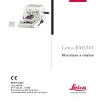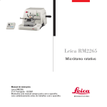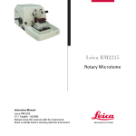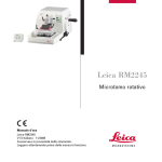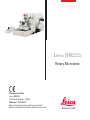
1
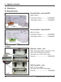
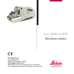
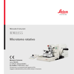
Leica RM2255
Rotary Microtome
Instructions for Use
Leica RM2255
V1.6 Rev A English – 10/2011
Order no. 14 0502 80101
Always keep this manual with the instrument.
Read carefully before working with the instrument.
NOTE
The information, numerical data, notes and value judgments contained in this manual represent the current state of scientific knowledge
and state-of-the-art technology as we understand it following thorough investigation in this
field.
We are under no obligation to update the
present manual periodically and on an ongoing
basis according to the latest technical developments, nor to provide our customers with additional copies, updates etc. of this manual.
For erroneous statements, drawings, technical
illustrations etc. contained in this manual we
exclude liability as far as permissible according
to the national legal system applicable in each
individual case.
In particular, no liability whatsoever is accepted for any financial loss or consequential damage caused by or related to compliance with
statements or other information in this manual.
Statements, drawings, illustrations and other information as regards contents or technical details of the present Instructions for Use are not
to be considered as warranted characteristics
of our products.
These are determined only by the contract provisions agreed between ourselves and our customers.
Leica reserves the right to change technical
specifications as well as manufacturing processes without prior notice. Only in this way is it
possible continuously to improve the technology and manufacturing techniques used in our
products.
This document is protected under copyright
laws. Any copyrights of this document are
retained by Leica Biosystems Nussloch GmbH.
Any reproduction of text and illustrations (or of
any parts thereof) by means of print, photocopy,
microfiche, web cam or other methods – including any electronic systems and media –
requires express prior permission in writing by
Leica Biosystems Nussloch GmbH.
For the instrument serial number and year of
manufacture, please refer to the identification
label attached to the instrument.
© Leica Biosystems Nussloch GmbH
Published by:
Leica Biosystems Nussloch GmbH
Heidelberger Str. 17-19
D-69226 Nussloch
Germany
Phone: +49 6224 143-0
Fax:
+49 6224 143-268
Internet: http://www.leica-microsystems.com
Leica RM2255
3
Table of contents
1.
Important notes ....................................................................................................................................... 6
1.1
1.2
1.3
1.4
2.
Safety ........................................................................................................................................................ 8
2.1
2.2
2.3
3.
Installation site requirements ............................................................................................................ 17
Standard delivery ................................................................................................................................. 17
Unpacking and installation ................................................................................................................. 18
Assembling the handwheel ................................................................................................................ 20
Electrical connections ........................................................................................................................ 20
Operation ................................................................................................................................................ 23
5.1
5.1.1
5.1.2
5.2
5.3
5.4
5.5
5.6
5.7
5.8
5.9
5.9.1
5.9.2
5.10
5.11
6.
Overview — instrument components ............................................................................................... 13
Instrument Specifications .................................................................................................................. 14
Technical data ...................................................................................................................................... 15
Startup .................................................................................................................................................... 17
4.1
4.2
4.3
4.4
4.5
5.
Safety notes ............................................................................................................................................ 8
Warnings ................................................................................................................................................. 8
Integrated safety devices ................................................................................................................... 11
Instrument components and specifications .................................................................................... 13
3.1
3.2
3.3
4.
Symbols used in this manual and their meaning .............................................................................. 6
Qualification of personnel .................................................................................................................... 7
Designated use ....................................................................................................................................... 7
Instrument type ...................................................................................................................................... 7
Operating elements and their functions ........................................................................................... 23
Instrument control panel .................................................................................................................... 23
Control panel......................................................................................................................................... 24
Switching on the instrument .............................................................................................................. 25
Display and control elements ............................................................................................................ 26
Inserting the knife holder .................................................................................................................... 37
Inserting the universal cassette clamp ............................................................................................ 38
Adjusting the clearance angle ........................................................................................................... 39
Clamping the specimen ....................................................................................................................... 40
Clamping the knife/disposable blade ................................................................................................ 40
Trimming the specimen ....................................................................................................................... 42
Trimming in manual sectioning mode ............................................................................................... 42
Trimming in motorized sectioning mode .......................................................................................... 42
Sectioning ............................................................................................................................................. 43
Changing the specimen or interrupting sectioning ........................................................................ 43
Optional accessories ........................................................................................................................... 44
6.1
Assembly for specimen holder fixture .............................................................................................. 44
6.1.1 Non-orientable specimen holder fixture .......................................................................................... 44
6.1.2 Directional fixture for specimen clamps .......................................................................................... 44
4
Instructions for Use V 1.6 RevA – 10/2011
Table of contents
6.1.3
6.1.4
6.2
6.2.1
6.2.2
6.2.3
6.2.4
6.2.5
6.2.6
6.2.7
6.3
6.3.1
6.3.2
6.3.3
6.4
6.4.1
6.4.2
6.5
6.6
6.7
6.8
6.9
6.10
6.11
6.12
6.13
7.
Customized solutions ........................................................................................................................... 70
7.1
7.1.1
7.1.2
7.2
8.
Instrument malfunctions ..................................................................................................................... 70
Error messages .................................................................................................................................... 70
Malfunctions, possible causes and troubleshooting ..................................................................... 70
Possible faults ...................................................................................................................................... 72
Cleaning and maintenance ................................................................................................................. 74
8.1
8.2
8.2.1
8.2.2
8.2.3
9.
Fine-directional specimen holder fixture ......................................................................................... 45
Quick clamping system ....................................................................................................................... 46
Specimen clamps and holders .......................................................................................................... 47
Standard specimen clamp .................................................................................................................. 47
Vee insert .............................................................................................................................................. 48
Foil clamp type 1 ................................................................................................................................... 49
Foil clamp type 2 ................................................................................................................................... 50
Universal cassette clamp ................................................................................................................... 51
Universal cassette clamp, ice-cooled .............................................................................................. 52
Round specimen holder ...................................................................................................................... 52
Super mega-cassette clamp .............................................................................................................. 53
Knife holder base and knife holder ................................................................................................... 54
Knife holder base, without lateral movement feature ................................................................... 54
Knife holder E/E-TC .............................................................................................................................. 55
Knife holder N/NZ ................................................................................................................................ 58
Blades/knives ....................................................................................................................................... 60
Disposable blades ................................................................................................................................ 60
Knife ....................................................................................................................................................... 60
Section waste tray ............................................................................................................................... 62
Backlighting .......................................................................................................................................... 62
Tray ........................................................................................................................................................ 63
Freezer pack ......................................................................................................................................... 63
Universal microscope carrier ............................................................................................................ 64
Magnifier ............................................................................................................................................... 66
Cold light source .................................................................................................................................. 67
Fiber optic light guides ........................................................................................................................ 67
Ordering information ........................................................................................................................... 68
Cleaning the instrument ...................................................................................................................... 74
Maintenance ........................................................................................................................................ 76
Replacing fuses .................................................................................................................................... 76
Maintenance instructions .................................................................................................................. 77
Lubricating the instrument ................................................................................................................. 78
Warranty and service .......................................................................................................................... 79
Leica RM2255
5
1.
Important notes
1.1 Symbols used in this manual and their
meaning
Warnings
appear in a gray box and are marked
by a warning triangle .
Notes,
i.e. important user information appear
in a gray box and are marked by an information symbol
.
(5)
Numbers in parentheses refer to item
numbers in illustrations.
RUN/
STOP
Function keys which must be pressed
on the control panel are shown in the
text in bold capital letters.
Manufacturer
This product fulfills the requirements
of the Council's Directive 98/79/EC
concerning in vitro diagnostics (IVD)
medical devices.
Symbol for labeling electrical and
electronic equipment in accordance
with Section 7 of the German Electrical
and Electronic Equipment Act
(ElektroG). ElektroG is the law on the
bringing into circulation, return and
environmentally compatible disposal of
electrical and electronic equipment.
The CSA test mark means that a product has been tested and fulfills the applicable safety and/or performance
standards, including the relevant standards defined or administered by the
American National Standards Institute
(ANSI), Underwriters Laboratories
(UL), the Canadian Standards Association (CSA), the National Sanitation
Foundation International (NSF) and
others.
Environmental protection symbol of the
China RoHS directive. The number in
the symbol indicates the "Environmentfriendly Use Period" of the product.
The symbol is used if a substance restricted in China is used in excess of
the maximum permitted limit.
In vitro diagnostics (IVD) medical
device
Observe the Instructions for Use
REF
Order No.
SN
Serial number
6
Instructions for Use V 1.6 RevA – 10/2011
1. Important information
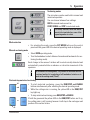
1.2 Qualification of personnel
1.4 Instrument type
• The Leica RM2255 may be operated by
trained laboratory personnel only.
All information provided in these Instructions
for Use applies only to the instrument type indicated on the title page.
An identification label with the serial number is
fastened to the left side of the instrument (this
figure is only symbolic).
• All laboratory personnel designated to operate the Leica instrument must read these Instructions for Use carefully and must be familiar with all technical features of the
instrument before attempting to operate it.
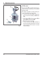
1.3 Designated use
The Leica RM2255 is a fully automatic, motorized rotary microtome with a separate control
panel for creating thin sections of specimens of
varying hardness for use in routine and research laboratories in the fields of biology,
medicine and industry.
It is designed for cutting both soft paraffin and
harder specimens, as long as they are suitable
for being cut manually or automatically.
Fig. 1
Any other use of the instrument is considered
improper!
Leica RM2255
7
2. Safety
Be sure to comply with the safety instructions and warnings provided in this chapter.
Be sure to read these instructions, even if you are already familiar with the operation and use
of other Leica products.
2.1 Safety notes
These Instructions for Use include important information related to the operating safety and
maintenance of the instrument.
The instruction manual is an important part of
the product, which must be read carefully prior
to startup and use and must always be kept
near the instrument.
These Instructions for Use must be appropriately supplemented as required
by the existing regulations on accident prevention and environmental
safety in the operator's country.
This instrument has been built and tested in accordance with the safety regulations for electrical measuring, control, regulating and laboratory devices.
To maintain this condition and ensure safe operation, the user must observe all notes and
warnings contained in these Instructions for
Use.
For current information about applicable standards, please refer to the CE declaration of conformity on our Internet site:
www.leica-microsystems.com
The protective devices on both instrument and accessories may neither be removed nor modified. Only service personnel qualified by Leica may repair the instrument and access the instrument’s internal components.
2.2 Warnings
The safety devices installed in this instrument by the manufacturer only constitute the basis
for accident prevention. Primarily responsible for accident-free operation is above all the owner of the instrument and, in addition, the designated personnel who operates, services or
cleans the instrument.
To ensure trouble-free operation of the instrument, make sure to comply with the following instructions and warnings.
8
Instructions for Use V 1.6 RevA – 10/2011
2. Safety
Warnings – Safety instructions / warning labels attached to the instrument
• Safety notes on the instrument itself marked with a warning triangle indicate that the correct
operating instructions (as defined in these instructions for use) must be followed when operating or replacing the item marked.
Failure to adhere to these instructions may result in an accident, personal injury, damage to the
instrument or accessory equipment.
Warnings – Transport and installation
• Once removed from the crate, the instrument may only be transported in an upright position.
• Never lift the instrument by the handwheels or the cassette clamp. Always remove the section
waste tray before transporting the instrument.
• Caution! The voltage selector has been preset at the factory.
Before connecting the instrument to the line voltage, please check that this setting complies
with the local power requirements of your laboratory.
The mains cable inlet is closed with an adhesive tape that indicates the actual voltage setting
of the instrument upon arrival. Severe damage can be caused to the instrument if the voltage
selector is set to an incorrect voltage!
• When changing the voltage selector setting, ensure that the instrument is not connected to the
mains power!
• Connect the instrument to a grounded power socket only using one of the power cables provided. Do not interfere with the grounding function by using an extension cord without a ground
wire.
• The instrument is ready for operation only if a dummy plug or foot switch (optional) is connected.
If you hear a beeping sound (continuous) after switching on the instrument, check that the control
panels are connected correctly.
• Do not operate in rooms with explosion hazard.
• Exposure to extreme temperature changes between storage and installation locations and high
air humidity may cause condensation inside the instrument. If this is the case, wait at least two
hours before switching on the instrument. Failure to comply with this may cause damage to the
instrument.
• The protective devices on both instrument and accessories must neither be removed nor modified.
Personal safety precautions
• When working with microtomes, personal safety precautions must always be taken. It is mandatory to wear work safety shoes, safety gloves, a mask and safety goggles.
Leica RM2255
9
2.
Safety
Warnings – Working at the instrument
• Take care when handling microtome knives and disposable blades. The cutting edge is extremely sharp and can cause severe injury!
• Always remove the knife / blade before detaching the knife holder from the instrument. Always
put the knives back into the knife case when not in use!
• Never place a knife anywhere with the cutting edge facing upwards and never try to catch a
falling knife!
• Always clamp the specimen block BEFORE clamping the knife or blade.
• Lock the handwheel and cover the knife edge with the knife guard prior to any manipulation of
knife or specimen clamp, prior to changing the specimen block and during all work breaks!
• ALWAYS turn the handwheel clockwise; otherwise, the brake will not work properly.
• Always take appropriate safety precautions when sectioning brittle specimens! Specimen
may splinter!
• Ensure that liquids do not enter the interior of the instrument during work!
• Do not attempt to clamp, approach or orient the specimen during the retraction phase.
If a block is oriented during retraction, the block will advance by the retraction value PLUS the
selected section thickness before the next section. This may cause damage to both specimens
and knife!
• The handle of the handwheel must always be centered while in motorized sectioning mode. Do
not touch the handwheel while it is running – there is a danger of injury from the handwheel
lock.
• Prior to sectioning, check that the specimen is securely clamped in the specimen clamp –
failure to observe this poses the risk of damaging the specimen.
Warnings – Cleaning and maintenance
• Only authorized and qualified service personnel may access the internal components of the
instrument for service and repair!
• Before each cleaning, switch off the instrument, disconnect the power plug, remove the knife
holder completely and clean it separately.
Always remove the blade before detaching the knife holder from the instrument.
• Lock the handwheel before each cleaning!
• Do not use any solvents containing acetone or xylene for cleaning!
• Ensure that no liquids enter the interior of the instrument when cleaning!
• Do not turn the instrument on before it is completely dry!
• When using detergents please comply with the safety precautions of the manufacturer.
• Turn the instrument off with the mains switch and pull the mains plug, before replacing the
fuses! Only use fuses of the same specification! For fuse specifications, refer to chapter 3.3 –
"Technical data".
10
Instructions for Use V 1.6 RevA – 10/2011
2. Safety
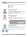
2.3 Integrated safety devices
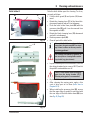
Emergency-stop function
The emergency-stop function is activated with the red
EMERGENCY STOP switch (1) on the upper left of the front
of the microtome. The sectioning motor stops immediately
when the EMERGENCY STOP switch is pressed. The red
LED in the E-STOP field (2) on the control panel of the
instrument lights up, indicating that the emergency stop
function has been activated.
To deactivate this function, turn the EMERGENCY STOP
switch in the direction of the arrow.
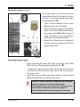
2
1
Fig. 2
Handwheel lock (manual operation only)
• To lock the handwheel, push the lever (5) outwards and
continue to turn the handwheel slowly until it locks
exactly in the 12 o’clock position. The LED (4) in the
LOCK display lights up.
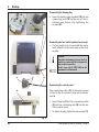
5
3
12
2
Caution!
Never operate the lever (5) during motorized
sectioning.
Handwheel brake
Using the lever (3) on the right side of the microtome base
plate, the handwheel can be braked in any position.
• To lock the handwheel, pull the lever forward forcefully.
• To unlock the handwheel brake, push the locking lever
(3) back to its original position.
4
Fig. 3
Important!
The LED (4) in the M-STOP field indicates only that the instrument cannot be started. It does not
provide any indication that the handwheel brake is active.
The lever (3) must be pulled completely forward with force so that the handwheel brake is
applied. The handwheel is securely locked only when the lever (5) is in the 12 o’clock position.
Leica RM2255
11
2.
Safety
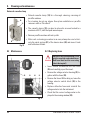
6
12
12
Fig. 4
7
8
7
Fig. 5
11
9
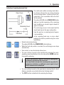
Knife guard on the knife holder
Each knife holder is equipped with a tightly
mounted knife guard (8, 9). This makes it possible to cover completely the cutting edge in every knife or blade position.
Knife holder N/NZ
The knife guard (8) of the knife holder N/NZ can
be easily positioned via the two handles (7)
(Fig. 5).
To cover the knife edge, push both cover strips
of the knife guard to the center.
Knife holder E
The knife guard on knife holder E consists of a
red foldaway handle. To cover the cutting edge,
fold the knife guard handle (9) upwards as illustrated in Fig. 6.
10
Fig. 6
12
Centering the handle
For safety reasons, the handle of the handwheel
must always be centered while in motorized
sectioning mode.
• Activate the handwheel lock.
• To center the handwheel, lightly pull the
handle (6) outwards and swivel it into the
center of the handwheel (12) (Fig. 4).
• The handle will then lock automatically
when released.
For the new knife holder E, the two
clamping levers (10, 11) must always
remain in the position shown. Clamping lever for the blade (10) at the right,
clamping lever for the lateral
displacement (11) at the left.
Instructions for Use V 1.6 RevA – 10/2011
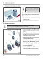
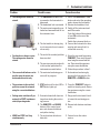
3. Instrument components and specifications
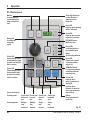
3.1 Overview — instrument components
Standard clamp
Knife holder NZ
Leica RM2255
Control panel
on the
instrument
Handwheel
locking
mechanism
Smooth-turning
Handwheel
Knife holder base
Emergency-stop
switch
Separate control panel
Lever for
activating the
handwheel
brake
Socket for
backlighting
Clamping lever
of knife holder base
Handwheel
handle with
centering function
Knife guard on the
knife holder
Section waste tray
Fig. 7
Leica RM2255
13
3. Instrument components and specifications
Rear side of instrument
Magnet for holding
the wrench
Heat sink
Voltage selector
switch with fuses
Main switch
Power supply
Motor protection
fuse
Connecting
cable for main
control panel
Connecting jack
for foot switch
Fig. 8
3.2 Instrument Specifications
The Leica RM2255 is a motorized rotary
microtome.
• The specimen feed system with zero-backlash and maintenance-free cross roller
guides and the stepper motor operated
coarse feed system are located in a dustproof plastic housing.
• The instrument is equipped with a safety
handwheel with a handle that can be
centered, as well as a mechanical handwheel lock.
• All controls and LEDs are centralized in a
separate control panel.
All control elements are logically arranged
in functional groups and easily identifiable.
14
• The specimen retraction can be turned off.
In manual operation the retraction can be
adjusted. In motorized operation the retraction value varies with the selected sectioning speed. An LED illuminates while the
sample is in retraction.
• The electric coarse feed operates at two
speeds. In the sectioning mode, the coarse
feed buttons have a STEP function.
• Three motorized sectioning modes (CONT,
SINGLE, and STEP) are available as well as
one manual sectioning mode, the rocking
mode ROCK.
In rocking mode, it is enough to move the
handwheel a short distance back and forth
in order to create a section.
Instructions for Use V 1.6 RevA – 10/2011
3. Instrument components and specifications
3.3 Technical data
General
Approvals:
Nominal supply voltages:
Nominal frequency:
Maximum power consumption
Protection class :
Power fuses
Pollution degree :
Overvoltage category :
Maximum heat emission:
Operating temperature range:
Temperature range during storage:
Relative humidity:
Storage humidity:
The instrument-specific approval marks are located
next to the identification label.
100 / 120 / 230 / 240 V AC ±10%
50/60 Hz
340 VA
I
2 x T 3.2 A UL listed
2
II
340 J/s
+10 °C to +35 °C
+5 °C to +55 °C
max. 80 %, non-condensing
< 80%
according to IEC-1010, UL 3101, EN 61010
Dimensions and weight
Basic instrument
Width (including handwheel):
Width (excluding handwheel):
Depth (including waste tray):
Height (total):
Working height (knife blade):
Working height (knife blade):
Weight (without accessories)
Control panel
Width:
Depth:
Height:
Height (in inclined position):
Weight (net):
Leica RM2255
413 mm
300 mm
618 mm
305 mm (with tray on the hood)
100 mm (measured from the base plate)
168 mm (measured from the table)
approx. 37 kg
121 mm
166 mm
50 mm
81 mm
approx. 0.660 kg
15
3.
Instrument components and specifications
Microtome
Sectioning thickness setting:
Section thickness setting range:
Setting:
0.50 – 100 µm
0.50 – 5.0 µm in 0.5 µm increments
5.0 – 20.0 µm in 1.0 µm increments
20.0 – 60.0 µm
in 5.0 µm increments
60.0 –100.0 µm
in 10.0 µm increments
Trimming section thickness setting range: 1 – 600 µm
Setting:
1.0 – 10.0 µm in 1.0 µm increments,
10.0 – 20.0 µm
in 2.0 µm increments,
20.0 – 50.0 µm
in 5.0 µm increments,
50.0 – 100.0 µm in 10.0 µm increments,
100.0 – 600.0 µm in 50.0 µm increments.
Object feed:
28 mm ±1 mm, feed motion via step motor
Vertical stroke:
70 mm
Maximum sectioning area w/o retraction: 65 mm without specimen orientation
Maximum sectioning area with retraction: 60 mm
16
Specimen retraction:
in manual sectioning mode:
in motorized sectioning mode:
5 - 100 µm in 5 µm increments; can be turned off
Varies with the sectioning speed; can be turned off
Electric coarse feed:
300 µm/s and 900 µm/s
Sectioning speed:
0; 0.5 - 420 mm/s ± 10%
Return speed
approx. 120 - 420 mm/s ± 10%
Repositioning of knife holder base
North-south:
East-west movement:
± 24 mm
± 23 mm
Maximum specimen size (L x H x W):
50 x 60 x 40 mm
Specimen orientation
Horizontal:
Vertical:
8°
8°
Instructions for Use V 1.6 RevA – 10/2011
4. Startup
4.1 Installation site requirements
• Stable, vibration-free laboratory bench with horizontal and even stage
plate; practically vibration-free floor.
• No other instruments nearby which might cause vibrations.
• Room temperature permanently between + 10 °C and + 35 °C.
• Obstruction-free access to the handwheel.
Never operate the instrument in rooms with explosion hazard.
4.2 Standard delivery
The Leica RM2255 standard delivery includes:
1 Leica RM2255 basic instrument
1 handwheel, complete .................................................................. 14 0502 37734
1 external control panel ................................................................. 14 0502 37950
1 section waste tray ........................................................................ 14 0502 37931
1 foot switch, dummy ..................................................................... 14 0443 30420
1 set of power cables consisting of:
1 power cable for Germany ..................................................... 14 0411 36958
1 power cable for USA/Canada/Japan ................................. 14 0411 36960
1 power cable for UK ST/BU F-5A ........................................... 14 0411 36959
1 tool set - consisting of: ................................................................ 14 0502 37965
1 Allen key with handle, size 5 ................................................. 14 0194 04760
1 Allen key with handle, size 4 ................................................. 14 0194 04782
1 Allen key size 3 ........................................................................ 14 0222 04138
1 screwdriver 3 x 50, 186 long ................................................... 14 0170 11568
1 bottle (50 ml) of oil for drive parts, type 405 ........................ 14 0336 06086
2 micro-fuses 3.2 AT .................................................................. 14 6943 03201
1 "Leica" brush with magnet ..................................................... 14 0183 40426
1 dust cover ................................................................................ 14 0212 30350
1 set of Instructions for use ........................................................... 14 0502 80001
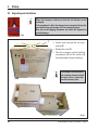
The accessories are included at the top of the package (item 2, Fig. 9).
Check the delivery carefully against the packing list, delivery note
and your order.
Should there be any discrepancy, please contact the Leica selling
unit handling your order.
Leica RM2255
17
4.
Startup
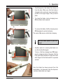
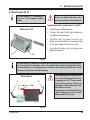
4.3 Unpacking and installation
When the instrument is delivered, check the tilt indicators on the
packaging.
If the arrowhead is blue, the shipment was transported laying flat,
was tilted at too great an angle or fell over during transport.
Note this on the shipping documents and check the shipment for
possible damage.
Fig. 9
1
• Loosen and unscrew the six upper
screws (2).
• Remove the cover (1).
• Take the accessory carton (optional
accessories) (3) and the cartons (4)
from the standard scope of delivery.
2
The transport crate and included retaining elements should
be kept in case a return shipment is necessary later.
3
4
5
4
4 4
Fig. 10
18
Instructions for Use V 1.6 RevA – 10/2011
4. Startup
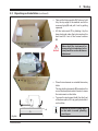
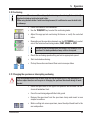
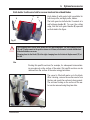
4.3 Unpacking and installation (continued)
•
•
5
6
Take out the fixing module (5). To do so, hold
it by the top edge of the module and in the
recessed grip (6) and pull it out by pulling
upwards.
Lift the instrument (7) by holding it by the
base plate and under the instrument on the
back and lift it out of the formed cushion
(8).
Never hold the instrument for
transport by the handwheel or the
rotary knob for section thickness
adjustment.
7
•
•
9
Place the instrument on a stable laboratory
table.
The two sliding elements (9) located on the
rear of the base plate make it easier to move
the instrument on the table.
To move the instrument, hold it by the front
of the base plate, lift it up gently and slide it
on its slides.
Observe the correct resting angle
to the table to avoid pinching
your fingers.
Fig. 10a
Leica RM2255
19
4.
Startup
4.4 Assembling the handwheel
The handwheel has to be assembled before attempting to use the instrument.
The necessary parts and tools can be found in the toolkit.
4
3
2a
1
2
The feather key (4) is loosely placed in the
handwheel shaft (1) and fixed in place with a
tie-rap during transport.
• Remove the cable tie (3). Caution!
Make sure not to lose the feather key!
• Place the handwheel (2) on the handwheel
shaft (1) as shown.
• Tighten the screw (2a) located in the center
hole of the handwheel with an Allen key size 4.
• Remove the cover foil from the self-adhesive
cover disk and fix the cover disk on the
handwheel.
Fig. 11
4.5 Electrical connections
The instrument MUST be connected to a grounded power socket. Use only the power cable
provided that matches the power supply (outlets) of the country of use. Do not use an extension
cable without a ground wire!
Checking the voltage
The Leica RM2255 can be connected to various
electrical power grids (depending on voltage
and frequency) and, for this reason, is always
delivered with a set of various power cables.
New instruments are factory-set to 230 volts.
This is documented by a yellow label (230 VOLT)
on the rear of the instrument, which covers the
power switch and power socket.
20
Before connecting the instrument to
the power supply, be absolutely certain to check that the voltage selector
is set to the voltage in use in your
area!
Severe damage can be caused to the
instrument if the voltage selector is
set to an incorrect voltage!
Never change the setting of the voltage selector while the instrument is
connected to the power supply.
Instructions for Use V 1.6 RevA – 10/2011
4. Startup
Checking the voltage (continued)
22
21
25
23
27
24
21
The voltage selector is located above the main
power switch, on the left-rear side of the instrument (Fig. 12). The voltage setting is displayed in
the viewing window (22).
• Insert a small screwdriver into the cutout
(25) and carefully pry out the insert.
• Remove the voltage selector housing (21) together with the fuses (23). Remove the voltage selector block (24) (white) and insert it
again such that the correct local voltage is
displayed in the viewing window (22).
• Reinsert the voltage selector housing with
the block and fuses and push it in until it engages (audible click).
26
Fig. 12
Connecting the power supply
• Before connecting the power cable, make sure that the power switch
(27) on the rear of the instrument is switched to 'O' = OFF.
• Various country-specific power cables are provided with the instrument. Make sure that the power cable used has the correct plug for
the power socket.
• Insert the connector of the power cable into the connection socket
(26) and plug the power plug into the power socket.
Exposure to extreme temperature changes and high air humidity
may cause condensation to form inside the instrument.
After transporting, please wait at least 2 hours to allow the instrument to adopt the ambient temperature before turning it on!
Failure to comply with this may cause damage to the instrument.
Leica RM2255
21
4.
Startup
20
18
19
15
Connecting the dummy plug
• Insert the dummy plug provided (18) into the
connecting jack (19) on the rear of the instrument and fasten it by tightening the
screws (20).
Connecting the foot switch (optional accessory)
• If a foot switch is to be used with the instrument, attach it in the same way as the dummy plug.
Caution!
If neither the dummy plug nor the foot
switch is connected, the instrument is
not ready for operation.
In this case, the E-STOP LED on the
instrument is illuminated.
14
17
15
Connecting the control panel
The connecting cable (15) of the control panel
is fixed to the microtome. It may not be disconnected.
16
• Insert the plug (14) of the connecting cable
(15) into the connecting jack (16) on the rear
of the control panel.
• To fasten the plug, tighten the two screws (17).
Fig. 13
22
Instructions for Use V 1.6 RevA – 10/2011
5. Operation
5.1 Operating elements and their functions
The operating functions of the microtome are divided between a control panel and a display
unit on the microtome.
A control panel on the instrument displays the current operating mode as well as various
settings.
All operating functions are centrally located in the separate control panel. All keys and
displays are logically arranged in functional groups and easily identifiable.
5.1.1 Instrument control panel
E-STOP LED
Lights up when emergency
stop function is activated.
M-STOP LED
Lights up when handwheel locking mechanism is activated.
RETRACT LED
Lights up during
specimen retraction.
Green LED
Lights up when trimming mode is activated.
Green LED
Lights up when sectioning mode is activated.
Three-digit display
for displaying
section thickness/trimming section thickness.
Green LED
Section thickness sum,
indicates the total
for all sections.
Four-digit display
of the section counter.
Green LED
Section counter displays
the number of all sections.
MENU MODE button
Switches between
section thickness sum
and section counter.
MENU MODE + CLEAR
pressed simultaneously
switches to the setting of
the retraction value.
Leica RM2255
CLEAR button
Resets the display
(section counter or
section thickness sum)
back (to 0).
Fig. 14
23
5.
Operation
5.1.2 Control panel
Buttons
for setting the section thickness/trimming section thickness.
Three-digit display for
section thickness/
trimming section
thickness.
Green LED
Lights up when trimming
mode is activated.
Green LED
Lights up when sectioning mode is activated.
Rotary knob
for setting the
sectioning
speed.
CUT MODE button
Mode selection
Green LEDs
For displaying the active operating mode
Button
Set sectioning window
Yellow LED
Flashes during coarse
feed backwards; lights
up when rear end position is reached.
Green LED
Flashes until second
sectioning window
edge is set.
TRIM/SECT button
For switching between
sectioning mode and
trimming mode.
Yellow LED
Flashes during coarse
feed forwards; lights
up when front end position is reached.
Yellow LED
Lights up when
motor is switched on.
Green LED
Lights up when
the motor is switched
off or stops at the next
stop position.
Coarse feed buttons
Trimming mode:
Coarse feed Coarse feed Coarse feed
backward forward
forward
fast
fast
slow
Coarse feed
backward
slow
Sectioning mode:
Multiple
step
backward
Single
step
backward
24
Multiple
step
forward
Single
step
forward
Buttons
Start/stop motorized
sectioning.
Fig. 15
Instructions for Use V 1.6 RevA – 10/2011
5. Operation
5.2 Switching on the instrument
When turning the instrument on with the mains switch, do not press any of the buttons of the
control panel or the foot switch (optional accessory)!
Ö
Turn the instrument on with the mains switch at the rear.
This is followed by a beep.
The instrument initializes.
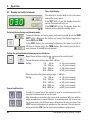
The display (here only as an example) of the software version follows in
the four-digit LED display. This display disappears after 2 seconds and
reads "0000".
After the microtome is switched on, the display fields and LEDs of all activated functions are lit up on the instrument’s control panel and display field.
2
4
The three-digit LED display indicates the last value set for the section
thickness or trimming thickness, depending on which setting was last activated. This is indicated simultaneously on the control panel and microtome.
The LED of the active mode (here the section thickness) is illuminated in
green.
When the red LED in the E-STOP field (2) on the control panel of the
instrument is illuminated, either
• the emergency-stop function has been activated (the EMERGENCY
STOP button is pressed or the foot switch depressed)
• the dummy plug (or the optional foot switch) is not correctly connected
to the jack, or not connected at all.
If the yellow LED in the M-STOP field (4) of the control panel is lit, the mechanical handwheel lock or the handwheel brake (Item 3 in Fig. 3) is activated.
The instrument cannot be started as long as the LED is lit.
Leica RM2255
25
5.
Operation
Three-digit display
5.3 Display and control elements
Fig. 16
This display is located both on the instrument
and on the control panel.
If the SECT LED is lit up, the display shows the
section thickness setting in µm.
If the TRIM LED is lit up, the display shows the
trimming section thickness setting in µm.
Selecting the sectioning and trimming mode
To switch between sectioning mode and trimming mode, press the TRIM
SECT button. Whenever the button is pressed, the display toggles between SECT and TRIM.
In the SECT display, the sectioning thickness in the range from 0.50 to
100.0 µm is shown, and in the TRIM display, the trimming section thickness between 1.0 and 600 µm is displayed.
Setting the section thickness/trimming section thickness
Adjust these settings using the
-
keys on the control panel.
Section thickness setting range: 0.50 - 100 µm
Setting:
0.5 - 5.0 µm
in 0.5 µm increments
5.0 - 20.0 µm
in 1.0 µm increments
20.0 - 60.0 µm
in 5.0 µm increments
60.0 - 100.0 µm
in 10.0 µm increments
Coarse feed functions
Trimming section thickness setting range: 1 - 600 µm
Setting:
1.0 - 10.0 µm
in 1.0 µm increments,
10.0 - 20.0 µm
in 2.0 µm increments,
20.0 - 50.0 µm
in 5.0 µm increments,
50.0 - 100.0 µm
in 10.0 µm increments,
100.0 - 600.0 µm
in 50.0 µm increments.
The electric coarse feed at two speeds is used for a rapid movement of the
specimen towards and away from the knife.
With the double-arrow buttons, the coarse feed operates at 900 µm/s; with the
single-arrow buttons, it runs at 300 µm/s. In sectioning mode, the coarse feed
can be operated in two different ways: defined step-by-step specimen feed
(STEP function) and continuous movement of the specimen. The instrument is
delivered with the STEP function deactivated (standard configuration).
26
Instructions for Use V 1.6 RevA – 10/2011
5. Operation
Sectioning mode
Button functions in
STEP mode
Multiple
step
backward
Single
step
backward
Single
step
forward
Multiple
step
forward
In sectioning mode the user can select between STEP function
(step-by-step specimen feed) and continuous specimen feed.
When continuous feed is selected, the coarse feed buttons have the same functions as in trimming mode. The STEP function is useful for careful step-by-step
approximation of the specimen towards the blade.
How to activate the STEP function:
• Switch the instrument on while holding the
button on the control panel.
(Likewise, to deactivate switch the instrument on while pressing the
button.) While the instrument is initializing, hold the
button until the software
version number is no longer displayed (ensure that version number 2.1 was
displayed).
This feature is only available in sectioning mode in version 2.1 or
higher. If you have an earlier software version, please contact
Leica Service.
•
•
•
•
Trimming mode
Press TRIM/SECT
button and select sectioning mode (LED SECT lit).
When pressing a slow-speed coarse feed button (with an arrow) in STEP
mode, the specimen moves towards or away from the specimen by the
value indicated on the display (single step).
By short activation of the buttons for coarse feed (with two arrows), a single step is also effected in the appropriate direction.
Longer activation of the double-arrow coarse feed button effects a repeated feed motion for as long as the button is pressed.
In the trimming mode, the coarse feed buttons operate a continuous
movement as long as the button is held down. The double-arrow
button for rapid coarse feed backward movements has a lock-in
function.
Do not put your fingers between the specimen clamp and microtome to prevent pinching them.
Backwards coarse feed
40
Leica RM2255
• To start the rapid backwards movement (away from the blade) press the
button.
button is pressed, the specimen head is moved to the rear
After the
end position.
• To stop the movement, press any of the four coarse feed buttons.
• The yellow LED (40) in the button flashes while the object head is in motion, and remains lit continuously when the rear end position is reached.
27
5.
Operation
Forward coarse feed
41
•
•
•
Press the
button to start the slow backwards movement.
The travel continues as long as the button is held depressed.
Press the appropriate button to start a rapid or slow forward movement. The
travel continues as long as the button is held depressed.
During the forwards movement, the yellow LED (41) in the button flashes.
When the front end position is reached, an acoustic signal is heard and the
LED stops flashing and remains lit.
Fig. 17
Four-digit display on the instrument
The four-digit display is adjustable.
When the Σ µm LED is lit, the display shows the
sum of the section thicknesses in µm for all sections completed since the instrument was
switched on.
(Section thickness sum)
When the Σ n LED is lit, the display shows the
number of all previously completed sections.
• To change the display mode, push MENU MODE until the LED of the
desired mode is illuminated.
• Press CLEAR to reset section thickness sum or section number.
• This will only reset the currently displayed value.
Caution! When the instrument is switched off using the main power
switch, both values (section thickness sum and section number) are
erased from memory.
Specimen retraction
To prevent damage to the blade and specimen, the specimen is moved
away from the blade during the return motion to the upper home position.
In motorized sectioning mode, the retraction depends on the setting
of the sectioning speed.
In manual mode, the retraction value can be selected in 5 µm increments
between 5 and 100 µm. Specimen retraction is set to 10 µm at the factory.
The specimen retraction can also be deactivated for the manual and motorized operation if required.
The selected setting is maintained when the instrument is turned off.
28
Instructions for Use V 1.6 RevA – 10/2011
5. Operation
Configuring the retraction settings
+
• To call up the retraction settings, press the MENU MODE and CLEAR
buttons simultaneously.
• The current set value is displayed as a three-digit number in the fourdigit display (e.g. "025" = 25 µm).
or
• Select the desired retraction value.
The retraction value can be adjusted in increments of 5 µm to a maximum of 100 µm using the
buttons on the control panel.
• To exit the retraction settings, press MENU MODE.
A retraction movement takes place by the newly selected value after
each section.
4
• While the specimen is in retraction, the yellow LED on the RETRACT
display (4) lights up.
Switching off the specimen retraction
+
• To call up the retraction settings, press MENU MODE and CLEAR
simultaneously.
• To switch off retraction, press the
the display indicates "OFF".
button on the control panel until
• To exit the retraction settings, press MENU MODE.
When retraction is switched off, the specimen is not retracted.
4
Leica RM2255
The yellow LED (4) of the RETRACT indicator does not light up.
29
5.
Operation
Setting the sectioning speed
• The sectioning speed can be set continuously (in the range of
0 - 420 mm/s) using the rotary knob.
The speed selector has a scale graduation from 1 to 10. The graduation
is provided for reference purposes and does not indicate a particular
speed.
The set sectioning speed is only active within the boundaries of
the sectioning area. A higher speed is used outside the sectioning
area.
Sectioning window setting
The sectioning window function allows to optimally adapt the size of the
sectioning area to the actual size of the specimen.
The selected sectioning window setting is maintained when the instrument is turned off.
43
• Turn the handwheel to position the lower edge of the sample approximately 3 mm above the cutting edge.
• Press the "SET SECTIONING WINDOW" button. This defines the first
window border.
• The green LED (43) in the button flashes after the first window border is
defined.
• Pass the specimen through to the upper border of the cutting edge and
press the "SET SECTIONING WINDOW" button again.
• After the second window border is defined, the green LED in the button
goes out. This indicates that both values were accepted.
To set a sectioning window, you must always enter a pair of values. The sequence of entry (upper or lower) is optional.
Canceling a defined sectioning window
• To cancel a defined sectioning window before the start, press the "SET
SECTIONING WINDOW" button once. This sets the sectioning area to
the maximum size (corresponding to the entire sectioning area).
30
Instructions for Use V 1.6 RevA – 10/2011
5. Operation
Sectioning modes
The microtome can be used both in manual and
motorized operation.
You can choose between four settings:
ROCK in manual mode as well as
CONT, SINGLE and STEP in motorized mode.
For safety reasons, when the instrument is first switched on, none of the
operating modes is active.
Mode selection
Fig. 18
• For selecting the mode, press the CUT MODE button on the control
panel until the green LED of the desired operating mode is displayed.
Manual sectioning mode
• Select ROCK operating mode.
• Turn the handwheel a short distance forwards and backwards for sectioning (rocking mode).
Each change in the sense of rotation will be electronically detected and
automatically converted into an advance or retraction movement of the
specimen.
In the manual sectioning mode, it is possible to use either the conventional method of completing a full handwheel rotation or to
work in the rocking mode ('Rock').
Start and stop motorized sectioning
44
• To start motorized sectioning, press the RUN/STOP and ENABLE
buttons simultaneously after selecting the desired operating mode.
and
• While the cutting motor is running, the yellow LED in the RUN/STOP
key lights up.
• To stop motorized sectioning, press RUN/STOP or ENABLE.
If both the green and the yellow LEDs in the RUN/STOP button are lit up,
or
the cutting motor is still running; however it will stop in the next upper end
position of the vertical stroke.
45
Leica RM2255
31
5.
Operation
Motorized sectioning
In motorized operation, you can choose between three operating modes:
CONT = continuous stroke,
SINGLE = single stroke
STEP = step stroke
CONT (continuous stroke) operating mode
• Select CONT operating mode.
After beginning the sectioning process, sectioning continues until the
process is stopped by pressing RUN/STOP or ENABLE.
The specimen then stops automatically in the next upper end position of
the vertical stroke.
SINGLE (single stroke) operating mode
• Select SINGLE operating mode.
After starting sectioning, a single sectioning stroke is completed.
The specimen then stops automatically in the upper end position of the
vertical stroke.
In motorized sectioning mode, the sectioning process can be started and stopped with the foot switch (optional accessory) instead of
the RUN/STOP and ENABLE buttons.
See chapter "Foot switches" (p. 32).
STEP (step stroke) operating mode
• Select STEP (step stroke) operating mode.
After starting the sectioning process, the specimen is moved as long as
the keys are held depressed (or as long as the foot pedal is pressed).
and
32
If the buttons or the foot switch are released, the specimen stops automatically.
Instructions for Use V 1.6 RevA – 10/2011
5. Operation
Indication of remaining horizontal feed
The visible and audible remaining feed indication feature informs the user during trimming
Object head
and sectioning when a remaining feed of approximately 1 mm is available before the front
limit is reached.
The yellow LED (41) in the COARSE FEED button
lights up from the beginning of the remaining
feed. In addition, an acoustic signal is heard for
approx. 2 seconds.
Remaining travel
The sectioning process is interrupted and the
object head stops in the upper end position.
From this point on, a remaining feed of approx.
Total feed
1 mm is available.
In the remaining feed area, no more object
Fig. 19
feeding to the knife is possible using the coarse
feed buttons.
• Restart motorized sectioning.
The yellow LED (41) in the COARSE FEED button lights up.
• When the front end position is reached, the sectioning process stops
automatically.
• Upon restart, no more feed motion takes place.
• You can continue to work on the specimen by pressing the corresponding coarse feed button in the rear end position (HOME) and continuing with sectioning.
41
HOME
and
or
To do so, you must press TRIM/SECT to switch to trimming mode,
as otherwise, you cannot use the coarse feed.
If the object head is already in the remaining feed range when the
instrument is switched on, an additional acoustic signal is heard
after the software version is displayed.
• You can continue to work on the specimen by moving it back a short
distance using the coarse feed buttons (set trimming mode!).
• The STEP function is disabled in the remaining feed range.
Leica RM2255
33
5.
Operation
Foot switch (optional accessory)
The foot switch can be used to control the motorized sectioning process.
It also has a function that is similar to the emergency stop function.
Caution!
In addition to the foot switch, all control panel functions and all
buttons on the instrument continue to be active.
• Using the CUT MODE button, select the desired operating mode, CONT,
SINGLE or STEP, on the control panel (Fig. 18).
CONT (continuous stroke) operating mode
• Press the foot switch once briefly to start motorized sectioning.
If the foot switch remains pressed for longer than half a second,
the specimen stops in the next upper end position.
• Press the foot switch again to stop it.
The specimen stops in the next upper end position.
SINGLE (single stroke) operating mode
• Press the foot switch once briefly to start motorized sectioning. After
every step, the specimen stops automatically in the upper end position.
STEP (step stroke) operating mode
• Press down the foot switch to start the sectioning process. The specimen is now moved for as long as the foot switch is depressed.
• If the foot switch is released, the specimen remains stationary in the
position that it has reached.
How to activate the emergency stop function
• Press the foot switch strongly to activate the emergency stop function.
Sectioning stops immediately.
The red LED in the E-STOP field on the instrument (Fig. 14) is lit up as
long as the foot switch remains depressed.
• To continue, restart the sectioning process using the foot switch. The
operating mode remains unchanged.
34
Instructions for Use V 1.6 RevA – 10/2011
5. Operation
Directional fixture for specimen clamps
In the quick clamping device of the directional specimen holder fixture, all specimen clamps
available as optional accessories can be used (implemented).
The object orientation allows for simple position
correction of the specimen surface when the
specimen is clamped into place.
The directional specimen holder fixture may be
exchanged for a non-directional fixture (optional accessory).
Orienting the specimen
30
32
32
31
29
Fig. 20
Display of the zero position
For better display of the zero position, the orientation has two red indicators (32).
When both indicators are visible and both setscrews (30,31) are in zero position at the same
R ") the
time (notch point, white marking on "R
specimen is in zero position.
When the large standard specimen
clamp (50 x 55 mm) is used, the specimen orientation of 8° in north-south
direction is no longer possible.
The usable angle is only about 4° in
this case.
Leica RM2255
Specimen blocks must not be oriented
during the retraction phase!
If a block is oriented during retraction,
the block will advance by the retraction value PLUS the selected section
thickness before the next section.
This may cause damage to both specimen and knife!
• Raise the object head to the upper end position and activate the handwheel lock.
• To release the clamp, turn the eccentric lever (29) forwards.
• Turn setscrew (30) to orient the specimen in
north-south direction. Turn setscrew (31) to
orient the specimen in east-west direction.
Each complete turn of the screw inclines the
specimen by 2°. A total of 4 complete turns =
8° are possible in every direction. The accuracy is approximately ± 0.5°.
For ease of estimation, there is a white mark
on the handle and a click stops that is noticeable during turning.
• To lock the current orientation, turn the eccentric lever (29) backwards.
35
5.
Operation
33
Fig. 21
Important!
Never turn the
screw more
than 1/2 turn at
a time.
Fine adjustment of the force balance
If another accessory of a different weight is
mounted on the object head (33), you must
check whether it is necessary to readjust the
force balance.
Checking the correct setting:
• Attach the new accessory and clamp the
specimen.
• Set the object head to half the height of the
vertical travel range by turning the handwheel (Fig. 21).
If the object head remains in this exact position,
the setting is correct.
If the object head moves, i.e. it is raised or lowered, fine adjustment is necessary.
Failure to adjust the force balance
may result in injury while working.
The force balance is adjusted using the screw
(34), which can be accessed by removing the
section waste tray on the bottom of the base
plate of the microtome. Use the Allen key provided, size 5 (with handle!) for the adjustment.
• If the object head moves downwards, turn the
screw approx. 1/2 clockwise.
• If the object head moves upwards, turn the
screw (34) approx. 1/2 turn counterclockwise.
• Continue this procedure until the object
head no longer moves once released.
34
Fig. 22
36
Instructions for Use V 1.6 RevA – 10/2011
5. Operation
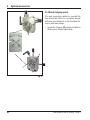
5.4 Inserting the knife holder
Setting up the knife holder base
• Release the clamping lever (50) by rotating it
counterclockwise.
• Insert the knife holder base (51) using the
notch (52) on the bottom into the T-piece (55)
of the microtome base plate (53).
• To secure the knife holder base, turn the
clamping lever (50) clockwise.
55
53
The knife holder base (51) can be moved back
and forth on the microtome base plate. This allows bringing the knife holder to optimal sectioning position in relation to the specimen.
There is a scale (54) on the right side of the microtome base plate. This enables faster and
better positioning of the knife holder at the
specimen if various combinations of standard
specimens and specimen holders are used. The
rear edge of the knife holder base (51) functions
as the scale reference.
50
52
Enlarged detail:
Scale for better
repositioning of the
knife holder for
varying specimen
heights.
51
54
Fig. 23
Inserting the knife holder
• Loosen the screw (58) using an Allen key
size 4 (71) until the knife holder (57) can be
moved.
56
• Place the knife holder (57) with the underside groove onto the T-piece (56) of the knife
holder base (51).
57
• To clamp, retighten the screw (58).
58
Fig. 24
Leica RM2255
37
5.
Operation
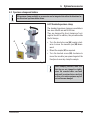
5.5 Inserting the universal cassette clamp
There are two versions of the specimen holder,
one with and one without specimen orientation,
which are interchangeable.
The object orientation allows for simple position
correction of the specimen surface when the
specimen is clamped into place.
60
12
You can use the specimen holder fixture (60) to
hold all available accessory specimen clamps
(for more information, see Chapter 6 "Optional
accessories").
To do so, proceed as follows:
• Move the specimen holder fixture (60) to the
upper end position by turning the handwheel
(12) and engage the handwheel lock.
62
• To release the clamping system, turn the
screw (61) counterclockwise using an Allen
key size 4 (71).
60
63
61
71
• Push the guide (63) of the specimen clamp
(62) from the left into the specimen holder
fixture (60) as far as it will go.
• To clamp the specimen clamp turn the
screw (61) clockwise as far as it will go.
Fig. 25
38
Instructions for Use V 1.6 RevA – 10/2011
5. Operation
5.6 Adjusting the clearance angle
• The index marks (0°, 5° and 10°) for adjustment of the clearance angle (59.1) are located on the right side of the knife holder (57).
57
• There is also an index mark (59.2) on the
right side of the knife holder basis (51) which
serves as a reference point when adjusting
the clearance angle.
51
Enlarged detail:
Index marks for
clearance angle
setting
• Loosen the screw (58) using an Allen key
size 4 (71) until the knife holder (57) can be
moved.
58
• Move the knife holder until the index mark of
the desired clearance angle coincides with
the reference line on the knife holder base.
Example:
The enlarged detail illustration shows a
clearance angle setting of 5°.
The recommended clearance angle
setting for knife holder E ranges from
a minimum of 2.5° to 5°.
59.1
59.2
71
• Hold down the knife holder in this position
and retighten the screw (58) for clamping.
Fig. 26
Leica RM2255
39
5.
Operation
5.7 Clamping the specimen
Always clamp the specimen block BEFORE clamping the knife.
Lock the handwheel and cover the knife edge with the knife guard
prior to any manipulation of knife or specimen, prior to changing
the specimen block and during all work breaks!
• Rotate the handwheel until the specimen clamp is in the uppermost
position.
• Activate the handwheel lock by allowing the handwheel handle to lock
in place and then activate the brake.
• Insert a specimen block into the specimen clamp.
A detailed description for inserting the specimen into various
specimen clamps and specimen holders is provided in Chapter 6
"Optional accessories".
5.8 Clamping the knife/disposable blade
Be very careful when handling microtome knives or blades. The
cutting edge is extremely sharp and can cause severe injury!
10
• Fold knife guard (9) downward.
• To insert the blade, flip the right clamping lever (10) forward and down.
9a
9
Fig. 27
40
Instructions for Use V 1.6 RevA – 10/2011
5. Operation
• Carefully push in the blade from above or
from the side. Make sure that the blade is
clamped in the center and, most importantly,
parallel to the upper edge of the pressure
plate.
10
• To clamp the blade, rotate clamping lever
(10) clockwise back upwards.
9a
9
10
• To remove the blade, fold the clamping lever
(10) downwards counterclockwise.
The ejector (9a) ensures safe blade changing.
Use the blade ejector to eject the
blade!
• Another option for removing the blade is to
use the brush with magnet.
To do so, fold the clamping lever (10) downwards counterclockwise. Likewise, fold the
knife guard (9) downward. Guide the brush
with magnet to the blade and lift it upwards
and out.
9
Once the blade has been removed from the
blade holder, it is disposed of into the dispenser
container (underside, see image).
Fig. 28
Leica RM2255
41
5.
Operation
5.9 Trimming the specimen
5.9.1 Trimming in manual sectioning mode
•
•
•
•
Use the TRIM/SECT key to select the trim mode.
Set the desired trim section thickness.
Deactivate the handwheel lock and release the brake.
In TRIM mode, use the coarse feed buttons to move the sample
against the knife/blade.
• Trim the sample by turning the handwheel
or
• Using the CUT MODE key, select the ROCK operating mode and cut the
specimen with forward and backward motions of the handwheel.
• Terminate trimming when the desired sectioning surface and depth
have been reached.
During fast manual trimming, do not put your fingers between the
specimen and knife. The handwheel continues turning after it is released and can cause injuries.
5.9.2 Trimming in motorized sectioning mode
The handle of the handwheel must always be centered while in
motorized sectioning mode. Always turn the handwheel evenly in
clockwise direction; otherwise, the brake will not work properly.
• Use the TRIM/SECT key to select the trim mode.
• Set the desired trim section thickness.
• If necessary, set the sectioning window.
Always set the sectioning speed according to the hardness of the
specimen! For hard specimens, always select a slow speed.
+
42
• Using the rotary knob, set the appropriate sectioning speed.
• Using the CUT MODE button, select the CONT operating mode (continuous stoke).
• Deactivate the handwheel lock and release the brake.
• Start motorized sectioning and trim the sample.
• Terminate trimming when the desired sectioning surface and depth
have been reached.
Instructions for Use V 1.6 RevA – 10/2011
5. Operation
5.10 Sectioning
Always use a different area of the cutting edge for trimming and sectioning. To do so, laterally
displace the blade or knife in the knife holder.
When using the knife holder E with lateral displacement, it is sufficient to move the knife holder sideways.
• Center the handle of the handwheel.
• Use the TRIM/SECT key to select the sectioning mode.
• Adjust the appropriate sectioning thickness or verify the selected
value.
• Depending on the operation planned, use the CUT MODE key to select
one of the motorized sectioning modes, CONT, SINGLE or STEP.
Always set the sectioning speed according to the hardness of the
specimen! For hard specimens, always select a slow speed.
• Check the sectioning speed setting and set an appropriate speed.
• Start motorized sectioning.
• Pick up the sections and mount them on microscope slides.
+
5.11 Changing the specimen or interrupting sectioning
Lock the handwheel and cover the knife edge with the knife guard prior to any manipulation of
knife or object head, as well as prior to changing the specimen block and during all work
breaks!
• Raise the specimen to the upper end position and activate the mechanical handwheel lock.
• Cover the sectioning edge with the knife guard.
• Remove the specimen from the specimen clamp and mount a new
sample to continue.
• Before cutting into a new specimen, move the object head back to the
rear end position.
Leica RM2255
43
6.
Optional accessories
6.1 Assembly for specimen holder fixture
Depending upon the purchase order, the basic instrument is delivered with the directional or
rigid fixture for specimen clamps which must be assembled first. All specimen clamps available as accessories can be used in both fixtures for specimen clamps.
Before assembling the fixture for specimen clamps, activate the mechanical handwheel lock!
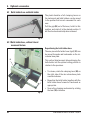
6.1.1 Non-orientable specimen holder
fixture
2
4
• Screw the rigid fixture for specimen clamps (4)
onto the object head (3):
Remove the screw (1), place the fixture for
specimen clamps (4) onto the object head (3)
from the front and tighten the screws (2) with an
Allen key size 3.
Next, insert the screw (1) from the side and
briefly tighten it with an Allen key size 4.
3
5
5
5a
5b
Remove the rubber ring only after attaching the object head!
Fig. 29
1
6
6.1.2 Directional fixture for specimen
clamps
3
•
•
7+8
2
•
•
1
•
7+8
Fig. 30
•
44
9b 9b 10 4
9a 9a
Finally, place the dovetail holder (2) and fasten
by screwing in the 4 screws (1) using an Allen
key size 3.
•
•
Loosen the eccentric bolt (6) by turning it
counterclockwise.
Completely unscrew the thrust piece (5) with a
flat-tip screwdriver and pull it out with spring
(5a) and pin (5b).
Completely unscrew the setscrews (3) and (4).
Attach the directional fixture for specimen
clamps as shown.
Insert the screws (7+8) in the bore (2 screws (8)
are accessible through the bore (9a) and evenly
screw them in using an Allen key size 3.
Insert the spring (5a) and pin (5b) with the flatter side into the thrust piece (5). Completely
screw in the thrust piece with a flat-tip screwdriver.
Completely screw in the setscrews (3+4).
Instructions for Use V 1.6 RevA – 10/2011
6. Optional accessories
6.1.3 Fine-directional
specimen holder fixture
• Before the fine-directional fixture for specimen clamps can be mounted, loosen
4 screws (10) (Allen key size 3) and carefully
remove the fixture for specimen clamps from
the baseplate (9).
10
9
12
• Using the 4 supplied screws (11) and the
Allen key size 3, fasten the baseplate to the
object head (12).
11
11
• Now, screw the fine-directional fixture for
specimen clamps with the 4 screws (10) and
the Allen key size 3 onto the object head.
If the fine-directional fixture for specimen clamps is not used, retain the
baseplate and 4 screws (11) together
with the fine-directional fixture for
specimen clamps!
Fig. 31
Leica RM2255
45
6.
Optional accessories
6.1.4 Quick clamping system
It is used as specimen holder for use with the
fine-directional fixture for specimen clamps
with zero point indicators or the directional fixture for specimen clamps.
• Screw the 4 screws (13) into bore A with an
Allen key size 2.5 and tighten them.
A
13
A
Fig. 32
46
Instructions for Use V 1.6 RevA – 10/2011
6. Optional accessories
6.2 Specimen clamps and holders
All specimen clamps available as accessories can be integrated into either the directional or
non-directional specimen holder fixture.
6.2.1 Standard specimen clamp
The standard specimen clamps are available in
two sizes: 40 x 40 mm and 50 x 55 mm.
They are designed for direct clamping of rectangular blocks. In addition, they accommodate
the foil clamps.
66
67
• Turn the knurled screw (66) counterclockwise to move the movable jaw (68) downward.
• Mount the sample (67) as required.
• Turn the knurled screw (66) clockwise to
move the movable jaw upward against the
fixed jaw to securely clamp the sample.
68
Fig. 33
When clamping cassettes, make sure
that they are not clamped too tightly,
since the cassette bodies can bend
and result in sections that are too thick
or thin, or the entire specimen may fall
out and become damaged.
Leica RM2255
47
6.
Optional accessories
6.2.2 Vee insert
66
69
70
70.1
68
Fig. 34
48
The vee insert (70) is mounted in the hole provided in the lower movable jaw of the standard
specimen clamp.
This makes it possible to clamp round specimens in the standard specimen clamp.
• Turn the knurled screw (66) counterclockwise to move the movable jaw (68) downward.
• Insert the pin (70.1) of the vee insert (70) in
the hole (69) of the lower jaw (68).
• Mount the sample as required.
• Turn the knurled screw (66) clockwise to
move the movable jaw with the vee insert
upward against the fixed jaw to securely
clamp the sample.
Instructions for Use V 1.6 RevA – 10/2011
6. Optional accessories
6.2.3 Foil clamp type 1
The foil clamp type 1 is appropriate both for
clamping very small foil pieces and flat, angular
samples. It is mounted in the standard specimen clamp.
66
74
73
72
71
75
Fig. 35
73
74
76
77
Clamping of foil pieces
• Move the movable jaw (74) to the right as required by turning the set screw with an Allen
key size 4 (71).
• Place the foil (72) between the movable jaw
(74) and the fixed jaw (73).
• To clamp the foil, screw the movable jaw
(74) against the fixed jaw (73) by using the
Allen key.
• Insert the foil clamp (75) in the standard
specimen clamp as shown.
• Turn the knurled screw (66) clockwise to
clamp the foil clamp in the standard specimen clamp.
Clamping of flat, angular samples
To clamp angular samples, replace the long
set screw (76) with the short set screw (77)
provided with the foil clamp.
• Unscrew the long set screw (76) to the left
with an Allen key size 4 (71).
• Screw the short set screw (77) in the hole.
• Place the sample (67) between the movable
jaw (74) and the fixed jaw (73).
• To clamp the sample, screw the movable
jaw (74) by turning the set screw (77) against
the fixed jaw (73).
• Insert the foil clamp in the standard specimen clamp as shown.
• Turn the knurled screw (66) clockwise to
clamp the foil clamp in the standard specimen clamp.
67
Fig. 36
Leica RM2255
49
6. Optional accessories
6.2.4 Foil clamp type 2
The foil clamp type 2 is appropriate for large foil ribbons.
It is mounted in the standard specimen clamp.
• To open the jaws (78) and (79) lightly loosen
the 3 screws (81) with an Allen key size 4
(71).
• Insert the foil ribbon (72) from behind to position it between the movable jaw (79) and
the fixed jaw (78).
• To clamp the foil, first tighten the screw in
the middle and then the other two screws
(81) with the Allen key (71).
• Place the foil clamp (82) in the standard
specimen clamp so that the beveled surface
(80) on the back of the foil clamp points to
the right or left.
• Turn the knurled screw (66) clockwise to securely clamp the foil clamp in the standard
specimen clamp.
66
72
78
79
80
82
81
71
Fig. 37
50
Instructions for Use V 1.6 RevA – 10/2011
6. Optional accessories
6.2.5 Universal cassette clamp
Prior to sectioning, laboratory personnel MUST check that the cassette is
seated securely in the universal cassette clamp.
60
• Push the lever (60) forwards.
• Mount the cassette (65) horizontally or vertically as required.
• To clamp the cassette, release the lever (60).
65
Fig. 38
Leica/Surgipath cassettes with
minimum dimensions of 39.8 x 28 mm and maximum dimensions of 40.9 x 28.8 mm can be
clamped horizontally as well as vertically in the Universal Cassette Clamp (UCC).
The use of other - particularly thin-walled - cassettes can lead to deformation of the cassette or
other problems with the clamping system. If, while clamping the cassette, the user determines
that it is not stably clamped into place, an alternative tensioning clamp must be used.
When using cassettes whose lid is molded on make sure that the broken edge left by removing
the lid does not prevent the specimen from being securely clamped – if necessary, the
specimen must be clamped horizontally.
Before clamping the cassette into the universal cassette clamp, remove excess wax on the
outside of the cassette to ensure that the cassette clamps in securely.
Wax deposits on the outside of the cassette can make the universal cassette clamp dirty. The
dirt prevents the cassette from clamping in securely and can lead to sections being too thick or
thin, chattering within the section and in the worst-case scenario, damage to the specimen.
Prior to sectioning, the user has to verify that the specimen is clamped securely and, if
necessary, remove wax deposits from the universal cassette clamp according to the
specifications in Chapter 8.1 "Cleaning and maintenance – Universal cassette clamp".
Leica RM2255
51
6.
Optional accessories
Universal cassette clamp, ice-cooled
Use the ice-cooled UCC with the nondirectional specimen holder fixture
only!
a
For use with standard cassettes with dimensions
that are 38.9 x 28mm at minimum and 40.9 x
28.8mm at maximum.
b
Fig. 39
• Ice cubes can be made using the included
Paraflex mold (a).
• Quick clamping system (b) refer to Chapter 6.1.4.
6.2.6 Round specimen holder
The holder for round specimens is designed to accommodate cylindrical samples.
Inserts for specimens of 6, 15 and 25 mm diameter are available.
92
89.1
89.2
91
90
89.3
67
93
• To mount the required insert (89.1-3) turn the
clamping ring (90) counterclockwise and remove it.
• Place the required insert into the tension
ring (90) and screw the tension ring onto the
thread (91) by turning it clockwise.
• Mount the sample (67) and fix by turning the
clamping ring (90) clockwise.
• To orient the inserted sample, insert the pin
(92) into the bore (93) and rotate it counterclockwise to release the clamp. You can
now rotate the specimen so that the side
you want faces upwards.
• To lock it in the position you have chosen,
tighten the pin (92) by turning it clockwise.
Fig. 40
52
Instructions for Use V 1.6 RevA – 10/2011
6. Optional accessories
6.2.7 Super mega-cassette clamp
2
3
4
5
1
Fig. 41
Assembly of the super mega-cassette clamp
The super mega-cassette clamp should preferably be used with the rigid
fixture for specimen clamps.
To do so, proceed as follows:
Remove the rubber ring (5) only after having attached the cassette
clamp on the object head!
• Screw the rigid fixture for specimen clamps (4) onto the object head (3):
Remove the screw (1), place the specimen holder fixture (4) onto the
specimen head (3) from the front and tighten the screws (2) with an
Allen key size 3.
Next, insert the screw (1) from the side and briefly tighten it with an
Allen key size 4.
• Insert the super mega-cassette clamp from the side on the left into the
dovetail guide of the rigid fixture for specimen clamps and tighten
screw (1).
If the directional fixture for specimen clamps is used with the rigid
knife holder base, the orientation must be in position "0" and the
cover for backlighting illumination must be detached. (Danger of
collision if not observed!)
NEVER use the super mega-cassette clamp with backlighting illumination!
Leica RM2255
53
6. Optional accessories
6.3 Knife holder base and knife holder
The plastic handles of all clamping levers on
the instrument and knife holders can be moved
to the position that is most convenient for each
user.
Pull the grip (94) out of the lever, hold it in this
position, and rotate it to the desired position. It
will then lock automatically when released.
94
Fig. 42
6.3.1 Knife holder base, without lateral
movement feature
Repositioning the knife holder base
The one-piece knife holder base (rigid) (51) can
be moved forwards and backwards on the microtome base plate.
This vertical displacement allows bringing the
knife holder into the optimal cutting position in
relation to the specimen.
51
50
Fig. 43
54
• To release, rotate the clamping lever (50) on
the right side of the microtome base plate
counterclockwise.
• Reposition the knife holder together with the
knife holder base forward or backward as
appropriate.
• Secure the clamping mechanism by rotating
the lever (50) clockwise.
Instructions for Use V 1.6 RevA – 10/2011
6. Optional accessories
6.3.2 Knife holder E/E-TC
The knife holder E-TC is designed for
the Leica TC-65 tungsten carbide
blades.
Prior to inserting the blade, both knife
holder and knife holder base must
have been installed on the instrument!
Inserting the blades, knife holder E and E-TC
• Fold knife guard (9) downward.
Knife holder E-TC
• To insert the blade, flip the right clamping lever (10) forward and down.
Õ
• Carefully insert the blade from the side.
Make sure that the blade is clamped parallel
to the upper edge of the pressure plate.
• To clamp the blade, rotate clamping lever
(10) back upwards.
9
10
Fig. 44
The knife holder E is designed for conventional disposable blades from all current manufacturers. It is available in two models: one for low profile, blades and one for high profile, blades.
The knife holder has a lateral displacement, so that the entire width of the blade can be used.
The ejector (9a) ensures safe blade changing.
The clamping levers on the knife holder are not interchangeable. The two
clamping levers (10, 11) must remain
in the position shown at all times, as
otherwise isolated malfunctions of the
knife holder can occur.
Clamping lever for the blade (10) at the
right, clamping lever for the lateral
displacement (11) at the left.
Knife holder E
10
11
9a
9
Fig. 45
Leica RM2255
55
6. Optional accessories
Knife holder E
10
13
11
B
A
12
Fig. 46
Lateral displacement (only for knife holder E)
The lateral displacement feature of the knife
holder base enables the use of the entire length
of the blade, eliminating the need for readjusting the knife holder. The knife holder E consists
of a segment arch A (with lever (11)) and the
clamp mount B (with lever (10) and ejector (13)).
The extreme left and right positions as well as
the middle position are each marked with a
click stop.
• To release the clamp, rotate the lever (11) on
the left side of the knife holder forwards.
• Move the knife holder sideways.
• To clamp, rotate the lever (11) back.
Note on the knife holder E:
The knife holder E is an important precision component, the quality and
precise adjustment of which have a lasting effect on the entire function of
the microtome. In case of malfunctions or damages to the clamp mount, it
is always required to replace the clamp mount, including the pertinent
clamping lever.
Leica Biosystems offers special prices for new clamp mounts in case of
damages to the clamp mount after the warranty has expired.
In this way, perfect function of the device can be ensured over the course
of many years.
Setting of the clamping system of the clamp mount on the segment arch
To ensure a proper sectioning result, clamp
mount B must be securely clamped onto segment arch A.
The clamping is carried out using an eccentric
at the lever (11). The clamping force is adjusted
with the setscrew (12) on the underside of the
segment arch. The setting of the clamping is
carried out so that the clamping lever can be rotated to the stop with constantly increasing resistance.
56
Adjust the clamping with a 2.5 mm Allen key at
the grubscrew (12) so that the lever initially
"slips" when the lever is activated. Continue
turning the grubscrew (12) a little bit (approx. 1/4
turn to the left or right), then check that the lever no longer "bars", but also does not jam
"heavily".
(The language CD features a short video film for
this purpose.)
Instructions for Use V 1.6 RevA – 10/2011
6. Optional accessories
Knife holder E with water bath for narrow-band and broad-band blades
9
11
Knife holder E with water bath is available for
both low profile, and high profile, blades.
The knife guard on knife holder E consists of a
red foldaway handle (9). To cover the cutting
edge, fold the knife guard handle (9) upwards
as illustrated in the figure.
10
Fig. 47
The clamping levers on the knife holder are not interchangeable. The two clamping levers
(10 and 11) must remain in the position shown at all times, as otherwise isolated malfunctions
of the knife holder can occur.
Clamping lever for the blade (10) at the right, clamping lever for the lateral displacement (11) at
the left.
Use
Floating thin paraffin sections (for example, for subsequent immunostaining procedures) on the surface of the water. Flat paraffin sections can be
removed from the surface of the water using glass slides.
The vessel is filled with water up to the blade.
After trimming, remove the section waste from
the tray and create the sections to be prepared.
The sections floating on the surface of the water can be removed using the glass slide.
Fig. 48
Leica RM2255
57
6. Optional accessories
6.3.3 Knife holder N/NZ
The knife holders N and NZ are appropriate for standard steel and tungsten carbide knives,
profile c and d, up to 16 cm long. The integrated height adjustment feature allows you to also
use knives that have been resharpened numerous times.
Mounting the knife support bar
• Push knife guard (8) to the center.
• Set the knife support bar (46) onto the height adjustment screws (not
visible) in the position shown. The flat ends of the height adjustment
screws must be located in the slots at each end of the knife support
bar.
Prior to inserting the knife, both knife holder and knife holder base
must have been installed on the instrument!
Enlarged detail:
Knife inserted and
height-adjusted
49
Knife holder NZ
For holding conventional and hard
metal knives up to 16 cm in length.
Knife pressure plate (56) for extreme
stability and full utilization of the
knife blade.
39
Knife holder N
For holding conventional
knives up to 16 cm in
length.
8
47
56
49
48
46
Fig. 49
58
Instructions for Use V 1.6 RevA – 10/2011
6. Optional accessories
Inserting the knife
• Rotate the knurled nuts (48) on the right and left of the knife holder
forward in opposite directions, lowering the knife support bar to the
lowest possible position, thus ensuring that the knife edge will not be
damaged when inserting the knife.
• Unscrew the clamping screws (49) as far out as possible (rotate counterclockwise).
• Hold the knife (47) at the knife base and carefully insert it in the holder
from the side as shown with the cutting edge facing upward.
Knife height adjustment
When adjusting the clearance angle, the knife edge should be positioned
as exactly as possible in the actual center of rotation of the knife holder.
The lay-on edge (39) of the rear clamping chucks serves as a reference
position for correct knife height adjustment. The knife edge should be parallel with the locating edges.
• Rotate the knurled nuts (48) uniformly and backwards until the knife
blade is parallel to the lay-on edge (39) (see detailed illustration) of the
rear clamping chucks.
• To clamp the knife (47) evenly screw the two knife clamping screws
(49) inward (rotate clockwise).
Lateral repositioning of the knife
•
•
•
•
Leica RM2255
Push knife guard (8) to the center.
Loosen the clamping screws (49) by turning them counterclockwise.
Push the knife (47) to the left or right as required.
To clamp the knife (47), always tighten the clamping screw (49) first
which is located on the side to which the knife has been repositioned
by turning it clockwise.
59
6. Optional accessories
6.4 Blades/knives
6.4.1 Disposable blades
Disposable blades - narrow band (819)
80 x 8 x 0.25 mm
01 Packages of 50 pcs..................... 14 0358 38925
10 Packages of 50 pcs..................... 14 0358 38382
Fig. 50
Disposable blades – high-profile (818)
80 x 14 x 0.317 mm
01 Packages of 50 pcs..................... 14 0358 38926
10 Packages of 50 pcs..................... 14 0358 38383
Fig. 51
6.4.2 Knife
Knife 16 cm – profile c – steel
Knife, 16 cm long, profile c (ground on both
sides, for paraffin and frozen sections)
Note: Knife case 14 0213 11140 included
Order No. ............................................14 0216 07100
Profile
Knife 12 cm profile c - steel
Knife, 12 cm long, profile c
Note: Knife case 14 0213 11140 included
Order No. ............................................14 0216 07092
Fig. 52
60
Instructions for Use V 1.6 RevA – 10/2011
6. Optional accessories
Knife 16 cm, profile d – steel
Knife, 16 cm long, profile d
Note: Knife case 14 0213 11140 included
Order No. ............................................ 14 0216 07132
Fig. 53
Knife 12 cm, profile d – steel
Knife, 12 cm long, profile d
Note: Knife case 14 0213 11140 included
Order No. ............................................ 14 0216 07130
Knife, 16 cm, profile d, tungsten carbide
Knife, 16 cm long, tungsten carbide, profile d
Note: Knife case 14 0213 11140 included
Order No. ............................................ 14 0216 04813
Serial number
hard metal
knife
Leica RM2255
Fig. 54
Knife 16 cm, profile c, tungsten carbide
Knife, 16 cm, tungsten carbide, profile c
Note: Knife case 14 0213 11140 included
Order No. ............................................ 14 0216 04206
Fig. 55
Knife case
Variable knife case (plastic),
for 1 or 2 knives: 10 – 16 cm long
(Hard metal or SM2500 knife: only for
1 knife!)
Order No. ............................................ 14 0213 11140
61
6. Optional accessories
6.5 Section waste tray
• Push the section waste tray (18) from the
front to the microtome base plate (53) until it
is held in place by the two magnets (39) (on
the front of the microtome base plate).
To remove the section waste tray, lift it
slightly and pull it off towards the back.
53
39
18
Fig. 56
6.6 Backlighting
1
1
The backlighting is inserted into the
front of the one-piece knife holder
base.
2
5
3
4
Fig. 57
62
• Remove the two screws (1) using a slotted
screwdriver and then remove the cover
plate (2).
• Insert the backlighting (3) in the recess at
the rear of the knife holder base.
• Connect the plug (4) of the backlighting to
the socket (5) on the microtome.
The backlighting illuminates once the microtome is turned on with the mains switch.
NEVER use the backlighting illumination with the super mega-cassette
clamp!
Instructions for Use V 1.6 RevA – 10/2011
6. Optional accessories
6.7 Tray
The tray is mounted on the hood of the microtome so that the small feet on the underside fit
into the cutouts on the hood.
It is for storage of the utensils used during sectioning as well as the sectioned specimens.
Fig. 58
6.8 Freezer pack
The freezer pack consists of the freezer plate
(98) and the insulation jacket (99). It is for cooling (or keeping cold) paraffin specimens. Up to
48 standard cassettes can be cooled at the
same time. The specimens require approx.
20 min. for being cooled from room temperature
(approx. 20 °C) to "sectioning temperature".
The cooling performance depends on the ambient temperature and the volume of the specimens being cooled.
The insulation jacket can be placed on the hood
of the microtome in the same manner as the
tray, or it can be placed next to the instrument.
98
When using the freezer pack on the
instrument the tray (Fig. 47) must be
removed.
98
99
Fig. 59
Leica RM2255
• Remove the freezer plate from the insulation
jacket and place it in a deep freezer, ideally
overnight (but for at least six hours) at
approx. -23 °C.
• Reassemble the freezer plate and insulation
jacket and place them on the bench or the
instrument.
63
6.
Optional accessories
6.9 Universal microscope carrier
a
Unpack all accessories in the package
and check for completeness.
1
Fig. 60
d
e
8
7
2
3
c
b
4
1 - Baseplate with drilling (a)
2 - Vertical column with size 8 cap screw (b) and
lock washer (c)
3 - Horizontal arm with cross-member (d) and support
ring (e)
4 - Support plate, large (for RM2235, RM2245 and
RM2255)
5 - Support plate, small (for RM2265)
6 - Allen key size 3
7 - 4 countersunk screws to install support plate
8 - Allen key size 8
6
5
Fig. 61
Assembling the universal microscope
carrier
1. Attach baseplate
• Select the large (5) or small (4) support plate,
depending on the microtome to be used.
• Attach the support plate to the baseplate with
the included 4 countersunk screws (7) using
the Allen key size 3 (6).
Fig. 62
64
Instructions for Use V 1.6 RevA – 10/2011
6. Optional accessories
b
c
Fig. 63
2. Attach vertical column
• Insert the cap screw (b) into the hole of the
baseplate from below. Place the lock washer
(c) on the cap screw from above.
• Thread the silver vertical column (2) onto the
baseplate from above and tighten with the
Allen key size 8.
The lock washer must be positioned
between the baseplate and vertical
column to prevent unintentional turning of the column.
2
A
Fig. 64
2
h
d
g
e
f
Extreme danger of tipping! After installing the vertical column, immediately
place the microtome onto the baseplate
so that the front feet of the microtome are
positioned in the shallow recesses (A).
3. Attach horizontal arm
• Slide the support ring (e) onto the vertical column and position it so that the lock nut (f) is
facing to the back. Tighten the lock nut.
• Slide the cross-member (d) onto the column.
Ensure that the lock screw (g) is facing to the
right of the baseplate. The horizontal arm must
be centered over the microscope.
• Slide the horizontal arm (3), flat side facing the
lock screw (g), into the cross-member (d) and
tighten.
For more information on connecting
and using the microscope, magnifying
lens or cold-light source, please see
the appropriate instructions for use.
Fig. 65
Leica RM2255
65
6. Optional accessories
6.10 Magnifier
1
The magnifying lens provides a 2x
magnification and can be used with
all Leica 2200 series rotary microtomes.
2
4
Fig. 66
• Open the screw (3) on the horizontal arm of
the microscope carrier in a counterclockwise direction.
• Insert the silver connection piece (1) as far
as it will go. Tighten the screw (3).
• The adapter (2) allows a fiber-optic light
guide to be installed.
3
• The instrument illustrations in Fig. 67 and
Fig. 68 are an example only.
Fig. 67
• Adjust the position of the magnifying lens to
the specimen being processed.
The magnifying lens can be swiveled completely to the side if necessary.
Always protect the magnifier glass from
exposure to direct sunlight! Exposure to
sunlight may cause a burning glass
effect.
Danger of fire!
• Use the provided protective cap (4) to cover
the magnifying lens.
Fig. 68
66
Instructions for Use V 1.6 RevA – 10/2011
6. Optional accessories
6.11 Cold light source
The cold light source may be operated
at the power supply voltage specified
on the identification label (on the underside of the instrument) only.
• Connect the power cable (1) to the connecting jack on the rear of the device.
• Plug the power plug into the power socket.
Before use, carefully read the separately provided Instructions for Use!
1
7
Fig. 69
6.12 Fiber optic light guides
6
• Attach the fiber-optic light guide (2) to the
adapter of the magnifying lens and secure it
in place in the bore (6) using the screw (5).
• Pull off the protective cap (3) from the end of
the fiber-optic light guide and keep it in a
safe place.
• Insert this end into the opening provided (4)
until it engages with a slight click.
• Switch on the Cold light source using the
power switch (7).
• Remove the protective caps (8) and align the
light guide with the specimen.
Fig. 70
5
8
2
4
3
Fig. 71
Leica RM2255
Fig. 72, Leica rotary microtome with installed optional
accessories: magnifying lens and fiber-optic light guide
67
6. Optional accessories
6.13 Ordering information
Specimen holder fixture, non-orientable, silver ............................................................ 14 0502 38160
Specimen holder fixture, directional, silver ................................................................... 14 0502 38949
Specimen holder fixture, directional, silver ................................................................... 14 0502 37717
Quick clamping system assembly ................................................................................... 14 0502 37718
Knife holder base, non-orientable, silver ....................................................................... 14 0502 37962
Knife holder N RM22xx, silver .......................................................................................... 14 0502 37993
Knife holder NZ RM22xx, silver ........................................................................................ 14 0502 37994
Knife holder E low-profile RM22xx, silver ...................................................................... 14 0502 37958
Knife holder E low-profile RM22xx, silver, with blade ejector .................................... 14 0502 40508
Knife holder E high-profile RM22xx, silver, with blade ejector ................................... 14 0502 40509
Knife holder E low-profile run-off tray RM22xx ............................................................. 14 0502 38961
Knife holder E high-profile run-off tray RM22xx ............................................................ 14 0502 39114
Knife holder E-TC RM22xx, silver .................................................................................... 14 0502 37997
Low-profile disposable blades, Type 819 (80 x 8 x 0.25 mm), 1x50 ................................ 14 0358 38925
High-profile disposable blades, Type 818 (80 x 14 x 0.317 mm), 1x50 .......................... 14 0358 38926
Knife 16 cm profile C, steel ................................................................................................ 14 0216 07100
Knife 16 cm profile D, steel ............................................................................................... 14 0216 07132
Knife 12 cm profile C, steel ................................................................................................ 14 0216 07092
Knife 12 cm profile D, steel ............................................................................................... 14 0216 07130
Knife 16 cm, TC-edge, profile D ........................................................................................ 14 0216 04813
Knife 16 cm, TC-edge, profile C ........................................................................................ 14 0216 04206
Knife holder case (plastic), variable width 10-16 cm .................................................... 14 0213 11140
Standard specimen clamp with adapter, 50 x 60, silver ............................................... 14 0502 38005
Standard specimen clamp with adapter, 40 x 40, silver ............................................... 14 0502 37998
V-insert for standard specimen clamp, silver ............................................................... 14 0502 38000
Universal cassette clamp (UCC) with adapter RM2125, silver ........................................ 14 0502 37999
Universal cassette clamp (UCC) - ice-cooled ............................................................... 14 0502 37793
Megaclamp assembly RM22xx, silver ............................................................................ 14 0502 38967
68
Instructions for Use V 1.6 RevA – 10/2011
6. Optional accessories
Foil clamp – type 1, black .................................................................................................. 14 0402 09307
Foil clamp – type 2, black .................................................................................................. 14 0402 26922
Round specimen holder, silver ........................................................................................ 14 0502 38001
Round specimen holder, 3 clamping rings, silver ......................................................... 14 0502 38002
Clamping ring, D = 6 mm .................................................................................................... 14 0356 08322
Clamping ring, D = 15 mm .................................................................................................. 14 0356 09200
Clamping ring, D = 25 mm .................................................................................................. 14 0356 08320
EM specimen holder fixture, black ................................................................................. 14 0502 29968
EM univ. specimen holder ................................................................................................ 14 0356 10868
EM flat specimen holder ................................................................................................... 14 0355 10405
EM holder special wrench ............................................................................................... 14 0356 10869
Universal microscope carrier assembly ........................................................................ 14 0502 40580
Magnifying lens assembly ................................................................................................ 14 0502 42790
Cold light sources
Leica CLS 100X, 100-120V/50-60 Hz ............................................................................ 14 0502 30214
Leica CLS 100X, 230V/50-60 Hz................................................................................... 14 0502 30215
Leica CLS 100X, 240V/50-60 Hz .................................................................................... 14 0502 30216
Fiber optic light guides ...................................................................................................... 14 0502 30028
Backlighting assembly ...................................................................................................... 14 0502 38719
Foot switch .......................................................................................................................... 14 0502 38257
Handrest for waste tray .................................................................................................... 14 0502 38770
Cooling device assembly .................................................................................................. 14 0502 38325
Section waste tray, large .................................................................................................. 14 0502 37931
Section waste tray, small ................................................................................................. 14 0503 39060
Demo Box RM22xx series ................................................................................................. 14 0502 38930
Tray ....................................................................................................................................... 14 0502 37932
"Leica" brush w/magnet .................................................................................................... 14 0183 40426
Leica RM2255
69
7. Customized solutions
7.1 Instrument malfunctions
Certain instrument malfunctions appear on the 3-digit LED display or are indicated through illuminated LED’s on the control panel.
7.1.1 Error messages
If the message "E 1" follows the software version indication after switching on the instrument, a loss of parameters has occurred.
• Press any key.
All parameters are then set back to the default values.
• Now all settings must be checked to see if the values are still correct.
The values may have to be reentered.
You can continue with your normal working routine.
7.1.2 Malfunctions, possible causes and troubleshooting
Following is a list of the most common problems which can arise while working with the instrument, along with possible causes and troubleshooting procedures.
If the malfunction cannot be remedied with any of the options listed in the table, or the problem
occurs repeatedly, inform the Leica Service Support immediately.
Problem
Possible cause
• No display; no reaction to buttons pressed after the instrument is switched on.
1. The power cable is not connect- 1. Check the connection of the
power cable.
ed correctly.
2. Replace the power fuses.
2. Power fuses are defective.
(see Chapter 8.2.1)
3. The cable of the control panel is 3. Check the connection of the
cable to the control panel.
not connected correctly.
4. The voltage selection switch is 4. Check the voltage setting and
correct it if necessary
set incorrectly.
(see Chapter 4.5).
70
Corrective action
Instructions for Use V 1.6 RevA – 10/2011
7. Customized solutions
Problem
Possible cause
Corrective action
• The cutting motor cannot be
started.
1. Unlock the EMERGENCY STOP
1. The EMERGENCY STOP button
button and select the operating
is pressed or the foot switch is
mode; release the foot switch.
depressed.
2. The handwheel lock is activated. 2. Release the handwheel lock.
3. The motor was temporarily over- 3. Switch off the instrument and
wait 30 seconds.
loaded and was switched off via
Push the button of the automatthe
automatic
fuse.
28
ic fuse (28) on the rear of the
instrument.
Switch the instrument back on.
4. Connect the foot switch or dum4. The foot switch or dummy plug
my plug and ensure that it is
is not connected or not connectconnected correctly.
ed
correctly.
Fig. 73
• Feed motion no longer occurs.
The cutting motor cannot be
started.
1. The end of the residual path has 1. Select the trim mode by pressing
been reached.
TRIM/SECT. Then return the specimen using the coarse feed button. Then retract the specimen
2. The specimen was already withusing the coarse feed button.
in the residual path when the
2. Follow the procedure in Item 1.
instrument was switched on.
• The coarse feed buttons can be
used to move the object in a
backwards direction only.
1. The motorized sectioning process is still in progress.
1. End motorized sectioning by
pressing the foot switch or the
RUN/STOP or ENABLE button.
• The specimen in the residual
path area cannot be returned
using the coarse feed buttons.
1. STEP mode is still active (LED in
SECT button lights up).
1. Press the TRIM/SECT button to
switch to trimming mode. Return
the specimen using the coarse
feed button.
• Cutting motor switches off prematurely in CONT (continuous
stroke) operating mode.
1. Foot switch was held down too
long when starting the sectioning process.
2. The RUN/STOP and ENABLE
buttons of the control panel
were not released simultaneously after starting.
1. Only press the foot switch briefly to start the sectioning process.
2. Release both buttons simultaneously.
• HOME and STOP are lit up
simultaneously.
1. The end position detection is
defective.
1. Contact Leica after-sales
service.
Leica RM2255
71
7. Customized solutions
7.2 Possible faults
Problem
Possible cause
Corrective action
1. Thick/thin sections
• Blade, knife holder or orientation • Reclamp the blade, knife holder or
orientation.
is not clamped properly.
The sections alternate between
being thick and thin, or there is
chattering in the sections, or the • The specimen is not clamped • Check that the cassette is securely clamped in the universal casspecimen is torn out of the emproperly.
sette clamp.
bedding. In extreme cases, there
•
If the universal cassette clamp is
are no sections whatsoever.
soiled by wax, clean the UCC
(refer to Chapter 8.1 – "Cleaning
and maintenance – Universal
Cassette Clamp")
• When using cassettes whose lid
is molded on, check that the broken edge allows the cassette to
be clamped securely; if necessary, remove burrs or clamp the
cassette into the universal cassette clamp horizontally instead of
vertically.
• If the cassette dimensions are
within the specified tolerances
and the cassette still cannot be
securely clamped into place, it
may be that the universal cassette
clamp is configured incorrectly or
is defective. In this case, have
Technical Service inspect and
reconfigure the universal cassette clamp.
• When using cassettes, particularly thin-walled cassettes, from a
company other than Leica or Surgipath, the cassette may become
deformed or other clamping problems may arise.
If while trying to clamp the cassette you realize that it is not securely clamped into place, an alternative tensioning clamp must
be used.
72
Instructions for Use V 1.6 RevA – 10/2011
7. Customized solutions
Problem
Possible cause
Corrective action
• The blade is dull.
• Laterally displace the knife holder or insert a new blade.
• The pressure plate is damaged or • Insert a new pressure plate or use
incorrectly adjusted.
a new knife holder.
• Clearance angle of the knife/ • Methodically experiment with
blade too small.
larger clearance angle settings
until you have found the optimum
angle.
2. Section compression
• The blade is dull.
• Use another area of the blade or
a new blade.
The sections are very compressed, show folds or are • The specimen is too warm.
• Cool the specimen before secsqueezed together.
tioning.
• The sectioning speed is too fast. • Reduce the sectioning speed.
3. "Stripes" in sections
For knife holder E
• There is an accumulation of par- • Remove paraffin from this area on
affin on the rear pressure plate of
a regular basis.
the knife holder.
• The sectioning speed is too fast. • Select a slower sectioning speed.
4. Noises during sectioning
The knife "sings" when sectioning • The clearance angle is too wide. • Methodically reduce the clearhard specimens. The sections
ance angle setting until you have
show scratches or chatter marks.
found the optimum angle.
• Insufficient clamping of specimen • Check all screw and clamp conclamp and/or knife holder.
nections on the specimen holder
system and the knife holder. If
necessary, tighten the levers and
screws.
5. High blade consumption
Leica RM2255
• Too great of a sectioning force • Adjust the sectioning speed and/
was applied.
or section thickness when sectioning. Select a thinner section.
73
8.
Cleaning and maintenance
8.1 Cleaning the instrument
Always remove the knife / blade before detaching the knife holder from the instrument.
Always put the knives back into the knife case when not in use!
Never place a knife anywhere with the cutting edge facing upwards and never try to catch a
falling knife!
When using cleaners, comply with the safety instructions of the manufacturer and the laborsafety regulations of your laboratory!
When cleaning the outer surfaces, do not use xylene, scouring powders or solvents containing
acetone or xylene. Xylene or acetone will damage the finished surfaces!
Ensure that liquids do not enter the interior of the instrument during cleaning!
Before each cleaning carry out the following preparatory steps:
• Raise the specimen clamp to the upper end
position and activate the handwheel lock.
• Switch the unit off and unplug it.
• Remove the blade from the knife holder and
insert it in the receptacle at the bottom of
the dispenser, or remove the knife from the
knife holder and put it back in the knife case.
• Remove knife holder base and knife holder
for cleaning.
Never place blade or knife holders
with/without base close to the edge of
the table to prevent them from falling
down.
• Remove the specimen from the specimen
clamp.
• Remove section waste with a dry brush.
• Remove specimen clamp and clean separately.
Instrument and outside surfaces
If necessary, the varnished outside surfaces of the control panels can be
cleaned with a mild commercial household cleaner or soap water and then
be wiped with a moist cloth.
To remove paraffin residue, xylene substitutes, paraffin oil, or paraffin removers such as "Para Gard" (Polysciences) can be used.
The instrument must be completely dry before it can be used again.
Cleaning the knife
Always wipe the knife from the back of the knife to the cutting edge. NEVER wipe in the opposite direction - risk of injury!
Clean using an alcohol-based solution or acetone.
74
Instructions for Use V 1.6 RevA – 10/2011
8. Cleaning and maintenance
Knife holder E
84
10
9
11
83
86
Fig. 74
Take the knife holder apart for cleaning. To do so,
proceed as follows:
• Fold the knife guard (9) and ejector (84) downward.
• Rotate the clamping lever (11) of the lateral displacement forwards and pull it out sideways.
• Push the knife holder base plate (86) with the
pressure plate (83) until it can be removed from
the segment arch (87).
• Rotate the blade clamping lever (10) downward
and pull it out sideways.
• Remove pressure plate (83).
• Clean all parts of the knife holder.
If several knife holders are cleaned at the
same time, the parts must NOT be mixed
up! Failure to adhere to this may result in
sectioning problems!
11
For cleaning and removal of paraffin, do
not use xylene or cleaning fluids containing alcohol (e.g. glass cleaner).
87
•
There is a burn hazard when removing the
parts from the drying chamber (65°C).
Wearing safety gloves is recommended!
86
•
•
•
83
Lay the removed parts on an absorbent cloth into
the drying chamber (up to a max. of 65 °C) and let
the paraffin contamination run off.
10
Dry knife holder and reassemble.
After cleaning the moving parts, apply a thin
coat of drive part oil to them (refer also to
Chapter 8.2.3).
When installing the pressure plate (83), ensure
that the upper edge is parallel to and level with
the rear edge of the knife holder base (86) (see
also Fig. 44, Page 53).
Fig. 75
Leica RM2255
75
8.
Cleaning and maintenance
Universal cassette clamp
• Detach cassette clamp (13) for a thorough cleaning, removing all
paraffin residues.
• For cleaning, do not use xylene. Use xylene substitutes or paraffin
removers such as "Para Gard."
60
13
• The cassette clamp (13) can also be placed in an oven heated to a
maximum of 65 °C, until the liquid wax escapes.
• Remove paraffin residues with a dry cloth.
91
Fig. 76
• After such a cleaning procedure in an oven, always be sure to lubricate the spiral springs (91) of the tension lever (60) and move it back
and forth several times.
8.2.1 Replacing fuses
8.2 Maintenance
21
Switch the unit off and unplug it. Use
only the supplied replacement fuses.
Both fuses must have the same rating
(check the imprint!).
22
25
23
24
21
• Insert a small screwdriver into the cutout
(25) and carefully pry out the insert.
• Remove the voltage selector housing (21) together with the fuses (23).
• Remove the fuses. While doing so, leave the
voltage selector switch block (24) in the
housing.
• Replace defective fuses and reinstall the
voltage selector into the instrument.
• Check that the correct voltage value is displayed in the viewing window (22).
Fig. 77
76
Instructions for Use V 1.6 RevA – 10/2011
8. Cleaning and maintenance
8.2.2 Maintenance instructions
Only authorized and qualified service personnel may access the internal components of the instrument for service and repair!
The instrument is basically maintenance-free.
To ensure trouble-free operation of the instrument over a long period of time, the following is recommended by Leica:
1. Thoroughly clean the instrument on a daily
3. Have the instrument inspected on a regular
basis.
basis by a qualified service technician authorized by Leica.
2. Enter into a service contract at the latest at
the end of the warranty period. For more inThe intervals depend on how heavily the information, please contact your local Leica
strument is used.
technical service center.
We recommend the following inspection intervals depending on the general workload of the instrument as defined in the two categories listed in the table:
Category I
Category II
Number of sections per day:
> 8,000 sections per day
< 8,000 sections per day
Workload (hours per day):
> 5 hours per day
< 5 hours per day
Sectioning speed:
Predominantly high sectioning speed
Slow to medium sectioning speed
Specimen material:
Working with soft and hard specimens
Predominantly soft specimen material
Maintenance:
Every 12 months
Every 24 months
↓
Leica RM2255
Note for inspection
• When the instrument reaches approx. 2 million performed strokes, the
code SEr always appears for approx. 3 seconds in the three-digit
display when the TRIM/SECT button is pressed
(switching between trimming and sectioning mode).
This is a reminder that the instrument must be inspected by an authorized Leica service technician, regardless of how heavily the instrument
has been used.
77
8.
Cleaning and maintenance
8.2.3 Lubricating the instrument
95
Once a month, lubricate the following parts with
the included drive parts oil No. 405 (1 - 2 drops
are enough).
96
Instrument and specimen holder:
• The clamping key (95) of the quick clamping
system.
• The T-piece (55) on the microtome base
plate.
• Guide rails (96) for the knife holder base on
the microtome base plate.
55
56
• The T-piece on the knife holder base (56).
11
88
10
97
8
Knife holder NZ
Knife holder E:
• Clamping lever (11) for the lateral displacement.
• T-piece (88) and guide (97) of the knife holder for the lateral displacement.
• Clamping lever (10) for the blade.
Knife holders N and NZ:
• Sliding surfaces of the finger guard (8).
• Knurled nuts (73) for measuring height
adjustment.
Knife holder N
73
Fig. 78
78
Instructions for Use V 1.6 RevA – 10/2011
9. Warranty and service
Warranty
Leica Biosystems Nussloch GmbH guarantees that the contractual product delivered has been subjected to a comprehensive quality control procedure based on the Leica in-house testing standards, and that the product is faultless and complies with all technical specifications and/or
agreed characteristics warranted.
The scope of the warranty is based on the content of the concluded
agreement. The warranty terms of your Leica sales organization or the organization from which you have purchased the contractual product shall
apply exclusively.
Service information
If you are in need of technical customer service or spare parts, please
contact your Leica representative or the Leica dealer where you purchased the instrument.
Please provide the following information:
•
•
•
•
Model name and serial number of the instrument.
Location of the instrument and name of the person to contact.
Reason for the service call.
Delivery date.
Decommissioning and disposal
The instrument or parts of the instrument must be disposed of according
to existing local applicable regulations.
Special attention should be paid to the lithium cell of the electronic circuit
board!
Leica RM2255
79
Notes
80
Instructions for Use V 1.6 RevA – 10/2011