1
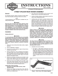
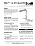
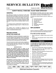
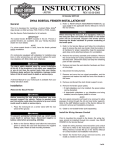
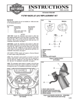
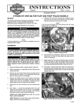
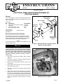
INSTRUCTIONS
®
REV. 11-30-99
-J01799
Kit Number 48046-99
ELECTRICAL PANEL MOUNT REINFORCEMENT KIT
(1996 Dyna Models)
General
i01876.eps
This kit is designed to reinforce the electrical panel frame
mount on Dyna Model motorcycles manufactured from July
1995 to April 1996.
Electrical Panel
Frame Mount
Nut
(2)
Electrical Panel
Kit Contents:
Qty
1
1
4
4
Description
Part Number
Plate electrical reinforcement repair
Guard, drill
Rivet, blind (.375 in. long)
Rivet, blind (.625 in. long)
47413-98
48362-99
8472
8473
Tools Required:
Rivet tool (POP)
#30 Drill bit
Electrical
Box Cover
Bracket
Stud
HD P/N 39787-A
Screw
(1)
Remove Electrical Panel Section
The electrical panel is located on the left side of the frame
and houses the motorcycle’s circuit breakers, turn signal
module and starter relay. The ignition module is located on
the panel frame mount behind the electrical panel.
NOTE
A Service Manual for your motorcycle is available from your
Harley-Davidson Dealer.
1WARNING
To avoid accidental start-up of motorcycle and possible
personal injury, disconnect the battery cables (negative
cable first) before performing any of the following
procedures. If the positive cable should contact ground
with the negative cable installed, the resulting sparks
may cause a battery explosion resulting in death or
serious injury.
1.
Screw
Figure 1. Electrical Box Cover, Electrical Panel,
Bracket, and Frame Mount
i01877.tif
Remove seat and disconnect battery cables, negative
cable first.
2.
See Figure 1. Remove four screws holding the electrical
box cover on and remove the cover.
3.
Remove four nuts that hold the bracket in place on the
bracket studs.
4.
Remove Black wire from silver post of circuit breaker.
Move panel out of the way.
5.
See Figure 2. Disconnect the ignition module 8-place
connector.
6.
Remove two nuts and one screw that hold the electrical
panel to frame mount. Push the Black wire (previously
removed from circuit breaker) with the grommet through
the hole in the electrical panel. Unplug the spark plug
wires from the coil (noting locations) and move the
panel with components to allow access to the frame
mount.
-J01799
Reinforcement
Plate Mounting
Location
Nut
(4)
Ignition
Module
Connector
Ignition Module
Figure 2. Disconnect Ignition Module and Remove
Module from Frame Mount
1 of 3
Access Frame Backbone
7.
8.
Following instructions in applicable Service Manual,
remove upper belt guard.
Following instructions in applicable Service Manual,
remove rear wheel assembly.
Install Reinforcement Plate to Electrical
Panel Frame Mount
9.
i01878.eps
Electrical
Panel Frame
Mount
Frame
Backbone
Long
Rivet
Insert drill guard carefully into backbone so that it is in
front of wire harness, until reaching stop tab
(approximately 12 in. from end).
10. See Figure 3. Look for and note cracked or damaged
areas on electrical panel frame mount. Sand and touchup areas with paint.
Short
Rivet
Reinforcement
Panel (plate)
Drill Hole
Locations
Figure 3. Electrical Panel Frame Mount and
Reinforcement Plate
i01879.eps
Hole in
Reinforcement
Plate Aligned with
Hole in Panel
11. See Figure 4. Align top of reinforcement plate with top of
electrical panel frame mount and hole in plate with hole
in panel frame mount. Clamp reinforcement plate
securely to frame mount.
NOTE
When performing the following Step, use care not to damage
wires under seat when drilling holes in frame mount.
12. See Figure 5. Using a #30 drill bit, drill eight (rivet) holes
in panel frame mount in locations shown using
reinforcement plate as a drill guide.
Reinforcement
Plate Aligned
with Top of
Panel
Figure 4. Align Reinforcement Plate
i01879.eps
13. Remove reinforcement plate.
Long
Rivets
14. Remove burrs and chips.
15. See Figure 5. Obtain four “long” (.625 in.) “pop” rivets.
Install through “inner” holes in reinforcement plate and
panel frame mount.
16. See Figure 5. Obtain four “short” (.375 in.) “pop” rivets.
Install through “outer” holes in reinforcement plate and
panel frame mount.
Reinforcement
Plate
17. Remove drill guard from frame backbone and discard.
18 Following instructions in applicable Service Manual,
install rear wheel assembly.
19. Following instructions in applicable Service Manual,
install belt guard.
Short
Rivets
Figure 5. Drill Holes and Install Rivets.
-J01799
2 of 3
Install Ignition Module and Electrical Panel
20. Install wire and grommet through hole in electrical panel.
21. See Figure 1. Install electrical panel to frame mount with
two nuts and one bolt.
1WARNING
Always connect positive battery cable first. If the
positive cable should contact ground with the negative
cable installed, the resulting sparks may cause a battery
explosion resulting in death or serious injury.
22. See Figure 2. Connect ignition module.
27. Connect battery cables, positive cable first.
23. Attach Black wire ring terminal to silver post of circuit
breaker.
24. Place bracket in place on mounting studs and secure
with four nuts.
1WARNING
25. Install spark plug wires on appropriate ignition coil
terminals.
After installing seat, pull upward on front of seat to be
sure it is locked in position. If seat is loose, it could shift
position during vehicle operation and startle the rider
resulting in loss of control and death or serious injury.
26. Install electrical panel cover using four screws.
28. Install seat.
-J01799
3 of 3