1
C
GE Consumer Home Services Training
TECHNICAL SERVICE GUIDE
LTMNF 22 and 25 Cubic Foot
GE/Hotpoint/Profile
Arctica Refrigerators with Electronic
Controls
MODEL SERIES:
ETS22
GTS22
HTS22
PTS22
PTS25
STS22
PUB #31-9077
05/01
!
IMPORTANT SAFETY NOTICE
The information in this service guide is intended for use by
individuals possessing adequate backgrounds of electrical,
electronic, and mechanical experience. Any attempt to repair a
major appliance may result in personal injury and proper ty
damage. The manufacturer or seller cannot be responsible for the
interpretation of this information, nor can it assume any liability in
connection with its use.
WARNING
To avoid personal injury, disconnect power before servicing this
product. If electrical power is required for diagnosis or test
purposes, disconnect the power immediately after performing the
necessary checks.
RECONNECT ALL GROUNDING DEVICES
If grounding wires, screws, straps, clips, nuts, or washers used
to complete a path to ground are removed for service, they must
be returned to their original position and properly fastened.
GE Consumer Home Services Training
Technical Service Guide
Copyright © 2001
All rights reserved. This service guide may not be reproduced in whole or in part
in any form without written permission from the General Electric Company.
TABLE OF CONTENTS
TECHNICAL DATA ........................................................................................................................ 2
MODEL NOMENCLATURE .......................................................................................................... 3
SERIAL NUMBERS ...................................................................................................................... 4
WARRANTY .................................................................................................................................. 5
RATING PLATE ............................................................................................................................ 6
MINI-MANUAL ............................................................................................................................. 6
DOOR REVERSAL ....................................................................................................................... 6
SHELVES AND BINS .................................................................................................................. 11
CABINET CONSTRUCTION ....................................................................................................... 15
Cabinet .................................................................................................................................. 15
Base Grille ............................................................................................................................. 15
Doors ..................................................................................................................................... 15
Door Gaskets ........................................................................................................................ 16
Rollers ................................................................................................................................... 16
ICEMAKER ................................................................................................................................. 17
Water Valve .......................................................................................................................... 17
AIRFLOW .................................................................................................................................... 18
Freezer Compartment ........................................................................................................... 18
Fresh Food Compartment .................................................................................................... 18
Evaporator Fan ..................................................................................................................... 19
Condenser Fan ..................................................................................................................... 22
DEFROST SYSTEM ................................................................................................................... 23
Adaptive Defrost ................................................................................................................... 23
Normal Operating Characteristics ....................................................................................... 24
Abnormal Operating Characteristics .................................................................................. 24
Liner Protection Mode .......................................................................................................... 24
Defrost Heater ....................................................................................................................... 25
Evaporator Thermistor ......................................................................................................... 25
Defrost Overtemperature Thermostat ................................................................................. 25
Defrost Probes ..................................................................................................................... 26
CONTROL SYSTEM ................................................................................................................... 27
Control Console .................................................................................................................... 27
Temperature Encoder ........................................................................................................... 27
Temperature Touch Panel .................................................................................................... 27
Control Board ....................................................................................................................... 28
Thermistors ........................................................................................................................... 35
ELECTRICAL SYSTEM .............................................................................................................. 36
Door Switches ....................................................................................................................... 36
Schematic .............................................................................................................................. 36
Wiring Diagram ..................................................................................................................... 37
REFRIGERATION SYSTEM ....................................................................................................... 38
Compressor .......................................................................................................................... 38
No-Clean Condenser ............................................................................................................ 38
Condenser Loop ................................................................................................................... 38
Dryer ...................................................................................................................................... 38
Evaporator............................................................................................................................. 38
Refrigerant Charge ............................................................................................................... 39
COMPONENT AND CONNECTOR LOCATOR VIEWS .............................................................. 40
FLOWCHARTS ........................................................................................................................... 45
–1–
TMNF - 22
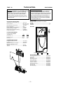
Technical Data
DISCONNECT POWER CORD BEFORE SERVICING
IMPORTANT-RECONNECT ALL GROUNDING DEVICES
All parts of this appliance capable of conducting
electrical current are grounded. If grounding wires,
screws, straps, clips, nuts or washers used to
complete a path to ground are removed for service,
they must be returned to their original position and
properly fastened.
ELECTRICAL SPECIFICATIONS
Temperature Control {Position 5) ................ 7-(-11 )°F
Defrost Control ............................................ 60hrs @ 45 min
w/ no door openings
Overtemperature Thermostat ...................... 140-110°F
Defrost Thermistor ...................................... 65°F
Electrical Rating: 115V. AC 60 Hz ............... 11.6 Amp
Maximum Current Leakage ......................... 0.75 mA.
Maximum Ground Path Resistance ............. 0.14 Ohms
Energy Consumption .................................. 40 KWH/mo.
NO LOAD PERFORMANCE
Control Position MID/MID
and Ambient of:
70°F
90°F
Fresh Food, °F ........................................... 34-40
Frozen Food, °F ......................................... (-3) 3
Run Time, % .............................................. <45%
34-40
(-3) 3
<70%
238C1616P001
IMPORTANT SAFETY NOTICE
This information is intended for use by individuals
possessing adequate backgrounds of electrical,
electronic and mechanical experience. Any attempt
to repair a major appliance may result in personal
injury and property damage. The manufacturer or
seller cannot be responsible for the interpretation
of this information, nor can it assume any liability
in connection with its use.
INSTALLATION
Clearance must be provided for air circulation
AT TOP ....................................................................... 1”
AT SIDES .................................................................... 1/8”
AT REAR .................................................................... 1”
AIR FLOW
REFRIGERATION SYSTEM
Refrigerant Charge (R134a) ....................... 4.5 ounces
Compressor ................................................ 762 BTU/hr
Minimum Compressor Capacity .................. 22 inches
Minimum Equalized Pressure
@ 70°F ......................................................... 30 PSIG
@ 90°F ......................................................... 38.5 PSIG
COLD AIR
MIXED AIR
WARMER AIR
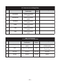
REPLACEMENT PARTS
Board Asm. Temperature Control ........................... wr55x10085
Relay (PTCR) .......................................................... wr07x0240
Overload ................................................................. wr08x10015
Run Capacitor (15 uF) ............................................ wr62x10079
Defrost Thermostat ................................................ wr50x10015
Defrost Heater Asm. ............................................... wr51x10038
Condenser Fan Motor ............................................. wr60x10053
Evaporator Fan Motor ............................................. wr60x10043
Board Asm. Main Control ........................................ wr55x10086
Thermistor (FF) ....................................................... wr55x10087
Thermistor (FZ) ...................................................... wr55x10088
Thermistor (Evap.) .................................................. wr55x10089
–2–
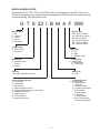
MODEL NOMENCLATURE
Model series ETS, GTS, HTS, and STS 22-cubic foot refrigerators, and PTS 22-and 25cubic foot refrigerators are energy-efficient refrigerators that will provide the consumer with
a quiet-operating, fully featured product.
G T S 22 I B M A F WW
Brand/Product
G - GE
H - Hotpoint
P - Profile
E - Eterna
S - GE Select
Exterior color
WW
- White
white
WW
- White
on on
White
AA
Almond
on
almond
AA - Almond on Almond
- Black
black
BBBB
- Black
onon
Black
CC
Bisque
on
Bisque
CC - Bisque on Bisque
WH
White
on
black
WH - White on Black
AD
- Almond
Black
AD
- Almond
onon
Black
Configuration
S - Side by Side
T - Top Mount
Door Type
F -F
Flat
- Flat
- Right door swing
R -RRight
- Left
door
swing
L -LLeft
Door
Swing
Depth/Power
S - Standard Depth
T - Tropical
G - Global
Engineering
A -A
Initial
Design
- Initial
Design
B -B
1st
Revision
- 1st Revision
Capacity
(cubic feet) AHAM Rated Volume
Model Year
M - 2001
Interior Features/Shelves
A - Leader Wire
D - Deluxe Wire
I - Deluxe Glass
K - Spillproof/Slideout Glass
M - Spillproof/Slideout Glass & Quickspace
Q - Showcase Derivative
U - AVB Derivative
W - HPS Derivative
X - Regional Derivative
Icemaker/Exterior
B - Non
Dispenser
B - Non
Dispenser
IM Ready
IM Ready
CubedIce/Water
ice/water
DD--Cubed
E
Cubed/crushed
E - Cubed/Crushed water
Water
F -- 6-Month
6 Month Filter
filter
F
Cubed/crushed
Cubed/Crushed
G - 1GYear
filter Filter
- 1-Year
Cubed/crushed
Cubed/Crushed
I - In-line
filter/indicator
I - In-line
Filter/Indicator
Cubed/crushed/water
Cubed/Crushed/Water
–3–
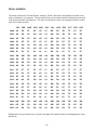
SERIAL NUMBERS
The serial numbers for General Electric, Hotpoint, Profile, and Arctica refrigerators consists of two
letters, followed by six numerals. The two prefix letters of the serial number indicate the month and
year the product was manufactured. The year of manufacture does not correspond with the model
year of the model number.
JAN
FEB
MAR
APR
MAY
JUN
JUL
AUG SEP
OCT
NOV
DEC
2000 AZ
DZ
FZ
GZ
HZ
LZ
MZ
RZ
SZ
TZ
VZ
ZZ
2001 AA
DA
FA
GA
HA
LA
MA
RA
SA
TA
VA
ZA
2002 AD
DD
FD
GD
HD
LD
MD
RD
SD
TD
VD
ZD
2003 AF
DF
FF
GF
HF
LF
MF
RF
SF
TF
VF
ZF
2004 AG
DG
FG
GG
HG
LG
MG
RG
SG
TG
VG
ZG
2005 AH
DH
FH
GH
HH
LH
MH
RH
SH
TH
VH
ZH
2006 AL
DL
FL
GL
HL
LL
ML
RL
SL
TL
VL
ZL
2007 AM
DM
FM
GM
HM
LM
MM
RM
SM
TM
VM
ZM
2008 AR
DR
FR
GR
HR
LR
MR
RR
SR
TR
VR
ZR
2009 AS
DS
FD
GS
HS
LS
MS
RS
SS
TS
VS
ZS
2010 AS
DS
FD
GS
HS
LS
MS
RS
SS
TS
VS
ZS
2011 AT
DT
FT
GT
HT
LT
MT
RT
ST
TT
VT
ZT
2012 AV
DV
FV
GV
HV
LV
MV
RV
SV
TV
VV
ZV
2013 AZ
DZ
FZ
GZ
HZ
LZ
MZ
RZ
SZ
TZ
VZ
ZZ
2014 AA
DA
FA
GA
HA
LA
MA
RA
SA
TA
VA
ZA
2015 AD
DD
FD
GD
HD
LD
MD
RD
SD
TD
VD
ZD
2016 AF
DF
FF
GF
HF
LF
MF
RF
SF
TF
VF
ZF
2017 AG
DG
FG
GG
HG
LG
MG
RG
SG
TG
VG
ZG
2018 AH
DH
FH
GH
HH
LH
MH
RH
SH
TH
VH
ZH
2019 AL
DL
FL
GL
HL
LL
ML
RL
SL
TL
VL
ZL
2020 AM
DM
FM
GM
HM
LM
MM
RM
SM
TM
VM
ZM
2021 AR
DR
FR
GR
HR
LR
MR
RR
SR
TR
VR
ZR
2022 AS
DS
FD
GS
HS
LS
MS
RS
SS
TS
VS
ZS
Refrigerators using a number four (4) as the first digit of the serial number are designated as Celya
production.
–4–
Refrigerator Warranty. (For customers in the United States)
All warranty service provided by our Factory Service Centers,
or an authorized Customer Care® technician. To schedule service,
on-line, 24 hours a day, contact us at www.GEAppliances.com, or
call 800-GE-CARES.
Staple your receipt here.
Proof of the original purchase
date is needed to obtain service
under the warranty.
For The Period Of:
GE Will Replace:
One Year
From the date of the
original purchase
Any part of the refrigerator (excluding water filter cartridge) which fails due to a defect in
materials or workmanship. During this full one-year warranty, GE will also provide, free of charge,
all labor and in-home service to replace the defective part.
Five Years
From the date of the
original purchase
Any part of the sealed refrigerating system (the compressor, condenser, evaporator and all
connecting tubing) which fails due to a defect in materials or workmanship. During this
five-year warranty, GE will also provide, free of charge, all labor and in-home service to replace
the defective part in the sealed refrigerating system.
What GE Will Not Cover:
■ Service trips to your home to teach you how to use
the product.
■ Replacement of house fuses or resetting of circuit
breakers.
■ Improper installation.
■ Damage to the product caused by accident, fire, floods
or acts of God.
■ Failure of the product if it is abused, misused, or
used for other than the intended purpose or
used commercially.
■ Incidental or consequential damage caused by possible
defects with this appliance.
■ Loss of food due to spoilage.
This warranty is extended to the original purchaser and any succeeding owner for products purchased for home
use within the USA. In Alaska, the warranty excludes the cost of shipping or service calls to your home.
Some states do not allow the exclusion or limitation of incidental or consequential damages. This warranty gives
you specific legal rights, and you may also have other rights which vary from state to state. To know what your
legal rights are, consult your local or state consumer affairs office or your state’s Attorney General.
Warrantor: General Electric Company. Louisville, KY 40225
–5–
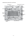
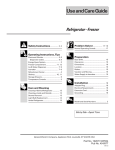
RATING PLATE
The rating plate, located inside the refrigerator
on the upper left-hand side, contains the model
and serial numbers. Additionally, the rating plate
specifies the minimum installation clearances,
electrical voltage, frequency, maximum
amperage rating, and refrigerant charge and
type.
Rating Plate Location
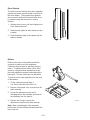
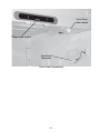
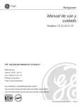
MINI-MANUAL
The mini-manual, located behind the base grille,
is secured to the underside of the cabinet for
shipping with a piece of tape. After referencing
the mini-manual, return it to its original location
for future use.
DOOR REVERSAL
Torx head (T-20) screws are used to mount the
top, center, and bottom hinges to the cabinet.
Mounting holes in the hinges are not elongated,
and the hinges are not adjustable. When
reinstalling the hinges, tighten screws firmly but
avoid overtightening to prevent stripping.
Mini-Manual Located Under Base Grille
Note:
• When reversing the door swing, read all
instructions thoroughly before starting.
• When handling parts, use caution to avoid
scratching paint.
• Sort screws to correspond with related parts
and be certain to use the proper screw with
each part.
• Place doors on a protected surface to
prevent damage.
• Once the door reversal procedure has been
initiated, do not move the cabinet until the
procedure is complete.
• Unplug the refrigerator from its electrical outlet.
• Empty all door shelves, including the dairy
compartment.
–6–
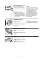
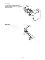
Freezer Door
1. Tape freezer door shut with masking tape.
Remove the hinge cover from the freezer
door hinge (some models).
2. Remove 2 (T-20) Torx head screws and the
top hinge.
Top Hinge
3. Remove the tape and tilt the door away from
the cabinet. Lift the door off the center hinge
pin and place on a protected surface.
Fresh Food Door
1. Tape the fresh food door shut with masking
tape.
2. Remove the center hinge pin with a 3/4-in.
socket.
3. Remove the tape and tilt the door away from
the cabinet. Lift the door straight up and off
the bottom hinge and place on a protected
surface.
Note: If the washer is not on the bottom hinge,
check to see if it is stuck to the bottom of the
door.
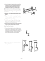
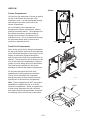
Reversing the Doors
1. Install the top hinge and screws on the
opposite side of the cabinet. Do not tighten
the screws at this time.
2. Remove the base grille by pulling it straight
out from the unit.
Note : If the washer is not on the bottom hinge,
check to see if it is stuck to the bottom of the
door.
3. Using a Torx driver, remove the screws and
bottom hinge from the cabinet and install on
the opposite side of the cabinet.
–7–
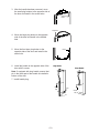
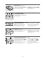
Hinge Pin
4. Cover the blade of a putty knife or small flat
screwdriver (to avoid scratching the paint)
and use the edge to gently pry the colormatched screw cap off the screw heads.
Note: Keep the screws with the center hinge.
These are longer screws and will be used when
installing the center hinge on the opposite side
of the cabinet.
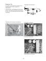
Screw Cap
5. Remove 3 Torx head screws and the center
hinge.
Mullion Cover
6. Remove the mullion cover using the putty
knife or screwdriver. Install the cover on the
opposite side of the cabinet.
7. Install the center hinge with the three long
screws on the opposite side of the cabinet.
Replace the color-matched cap.
8. Move the metal door stop and any associated
screws to the opposite side of the door.
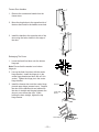
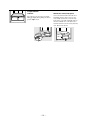
Fresh Food Door Handles
1. Remove the plug button by carefully prying
underneath the edge with a small, flat blade.
Remove the screw that fastens the bottom of
the handle to the door. Remove the lower
part of the long handle (some models).
Handle Plug
Long Handle
2. Remove the 2 screws and the handle from
the top of the door.
Short Handle
Short
Screw
Hole
Handle
Plug
Handle
Plug
Pin
–8–
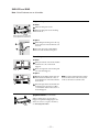
3. After the handle has been removed, move
the small plug buttons to the opposite side of
the door and install in the screw holes.
Small Plug
Buttons
Plug Button
4. Move the large plug button to the opposite
side of the door and install in the thimble
hole.
5. Move the front door plug button to the
opposite side of the door and install in the
screw hole.
Button
6. Install the handle to the opposite side of the
door with 3 screws.
Long Handle
Short Handle
Note: If equipped with long handle, ensure that
pin in the lower part of the handle is installed in
bottom of the door.
7. Install handle plug.
Handle
Plug
Hole
Handle
Plug
Pin
–9–
Freezer Door Handles
1. Remove the screws and handle from the
freezer door.
2. Move the plug button to the opposite side of
the door and install in the handle screw hole.
3. Install the handle to the opposite side of the
door using the holes closest to the edge of
the door.
Rehanging The Doors
1. Lower the fresh food door onto the bottom
hinge pin.
Note: Ensure that the washer is on bottom
hinge pin.
2. Line up the fresh food door with the center
hinge bracket. Install the hinge pin in the
center hinge bracket and door with a 3/4-in.
socket. Tighten the hinge pin in the center
hinge bracket.
3. Install the freezer door onto the center hinge
pin and upper hinge (screws loose). Support
the door on the handle side and make sure
the door is straight and the gap between the
doors is even across the front. While
holding the door straight, tighten the top
hinge screws.
Hinge Pin
Center Hinge
Bracket
Center Hinge Pin
– 10 –
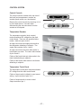
SHELVES and BINS
Note: Not all features are on all models.
Refrigerator Compartment
To remove:
Tilt the shelf up at the front.
Lift the shelf up at the back and bring
the shelf out.
Some models have wire shelves that
can be adjusted in the same manner.
To replace:
While tilting the shelf up, insert the top
hook at the back of the shelf in a slot on
the track.
Lower the front of the shelf until the
bottom of the shelf locks into place.
Freezer Compartment
To remove:
Lift up the left side of the shelf and slide
it left into the center of the shelf
supports.
Rotate the right side of the shelf up and
out of the shelf supports.
To replace:
Holding the shelf diagonally, insert the
left end of the shelf into the center of
the shelf supports on the side wall at the
desired level.
Insert the right end of the shelf into the
shelf supports at the same level. Rest
each end of the shelf on the bottom of
the shelf supports.
Spillproof Shelves (on some models)
Spillproof shelves have special edges to
help prevent spills from dripping to lower
shelves. To remove or replace the shelves,
see Rearranging the Shelves.
– 11 –
NOTE: For models with an automatic icemaker,
the freezer shelf must be in the lower position
for the ice cube bucket to catch the cubes.
Slide-Out Spillproof Shelf (on some models)
The slide-out spillproof shelf allows you
to reach items stored behind others. The
special edges are designed to help prevent
spills from dripping to lower shelves.
To remove:
Remove all items from shelf.
Slide the shelf out until it stops.
Finger hold
Snugger
To replace:
Place the rear shelf tabs just in front of
the central notches on the shelf frame.
Slide the shelf in until the central tabs
are slightly behind the front bar.
Lower the shelf into place until it is
horizontal and slide the shelf in.
Lift the front edge of the shelf until the
central tabs are above the front bar.
Make sure that the shelf sits flat after reinstallation
and doesn’t move freely from side to side.
Continue pulling the shelf forward until
it can be removed.
Make sure you push the shelves all the way in
before you close the door.
Adjustable Bins on the Door
Adjustable bins can easily be carried from
refrigerator to work area.
To remove: Lift bin straight up, then pull out.
To replace or relocate: Engage the bin in the
molded supports of the door, and push in.
Bin will lock in place.
Non-Adjustable Shelves on the Door
To remove: Lift the shelf straight up then
pull out.
To replace: Engage the shelf in the molded
supports on the door and push down. It will
lock in place.
Freezer Tilt Out Bin (on some models)
Push the button as you tilt out the bin.
To remove: Hold the sides of the bin and lift
it straight up, then pull out.
To replace: Engage the ends of the bin in
the molded supports on the door and push
down. It will lock in place.
NOTE: Do not overload the bin.
– 12 –
The snugger helps prevent tipping, spilling
or sliding of small items stored on the door
shelf. Grip the finger hold near the rear of
the snugger and move it to fit your needs.
Shelf Saver Rack (on some models)
Slide-out beverage rack holds twelve cans of
soda or two wine/water bottles (lengthwise).
It can be removed for cleaning.
To remove, slide the rack out to the stop
position, lift the rack up and past the stop
position and lift it out.
Fruit and Vegetable Crisper
Excess water that may accumulate in the
bottom of the drawers or under the drawers
should be wiped dry.
Adjustable Humidity Crisper (on some models)
Slide the control all the way to the
HIGH setting to provide high humidity
recommended for most vegetables.
Slide the control all the way to the LOW
setting to provide lower humidity levels
recommended for most fruits.
Snack Pan (on some models)
This pan can be moved to the most useful
location for your family’s needs.
To remove, slide the pan out to the stop
position, lift the pan up and past the stop
position and lift it out.
Adjustable Temperature Deli Pan (on some models)
When the pan is placed in the top 6 slots on
the left side and the lever is set at COLDEST,
air from the freezer is forced around the
pan to keep it very cold.
You can move the pan to any location if you
don’t want the extra cold storage.
– 13 –
The settings can be adjusted anywhere
.
between cold
and coldest
When set at cold, the pan will stay at the
normal refrigerator temperature.
The coldest setting provides the coldest
storage area.
Crisper Removal
To Remove:
These drawers can be removed easily by
lifting up slightly while pulling the drawer
past the stop location.
– 14 –
When the door cannot be fully opened,
remove the drawer farthest from the door
first. Make sure the drawer closest to the
door is fully closed. There is a latch at the
front of the center slide rail. Push down on
the latch and slide the center slide rail, to
which the drawer is attached, away from the
door. Remove the drawer.
CABINET CONSTRUCTION
Cabinet
The outer case is made of prepainted steel with
a textured finish. The fresh food and freezer
liners are made of plastic with a smooth finish.
Individual compartments provide separation and
enhanced individual control between the
compartments. The plastic liner provides a
thermal break between the interior of the
refrigerator and freezer compartments and
reduces the transfer of heat from the room into
the fresh food and freezer compartments. The
liner is not removable or replaceable.
Base Grille
The base grille is attached to the cabinet with
two steel spring retainers that clip into elongated
openings in the base channel. To remove the
grille, pull it straight forward.
GEA01144
GEA01145
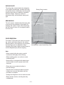
Doors
The doors are of one-piece construction with
foam insulation. One-piece construction
provides superior thermal performance and
reduces air infiltration. During manufacturing,
the doors are filled with hot foam insulation.
This may cause slight distortion or ripples in the
inner door liner. This is a normal condition and
is the result of the insulating process. This
process requires doors to be equipped with vent
holes that allow air to escape when the door is
filled with foam. A small amount of foam may be
visible around the vent holes.
The inner door panels and outer door panels
cannot be separated and must be replaced as
an assembly.
– 15 –
Vent Holes
GEA01138
Door Gaskets
The fresh food and freezer doors have magnetic
gaskets that create a positive seal to the front of
the steel cabinet. The magnetic door gaskets
are secured to the fresh food and freezer doors
by a barbed edge that locks into a retainer
channel.
1. Starting at any corner, pull the old gasket out
of the retainer channel.
2. Soak the new gasket in warm water to make
it pliable.
3. Push the barbed edge of the gasket into the
retainer channel.
GEA01150
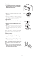
Rollers
Rollers at the base of the cabinet enable the
customer to easily move the refrigerator.
Cabinet leveling is done by adjusting the front
rollers. To adjust the front rollers, use a 3/8-in.
socket or a large flat head screwdriver to turn
the roller adjustment screws located behind the
base grille. The rear rollers are not adjustable.
To remove a front roller assembly from the base
of the cabinet:
1. Tilt the cabinet back and place a
3-in. block under the side of the unit.
2. Remove 3 hex head 1/4-in. screws from the
roller assembly.
3. Loosen the adjustment screw until it
disengages from the assembly and remove
the assembly from the cabinet.
4. Remove the E-ring to remove the
adjustment screw from the base channel.
GEA01147
Note: When reinstalling the roller assembly,
position the nut with the flared thread toward the
rear of the unit.
– 16 –
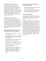
ICEMAKER
The 2001 LTMNF refrigerators use an
electronic icemaker. Refer to Pub. #31-9063 for
service information.
GEA01142
Water Valve
A single-coil, 120-VAC valve is secured to the
rear of the cabinet, inside the machine
compartment, on the left-hand side.
GEA01137
– 17 –
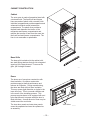
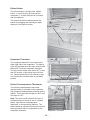
AIRFLOW
AIR FLOW
Airflow
Freezer Compartment
Cold air from the evaporator is forced up against
the top of the freezer and the back of the
evaporator cover. It is then discharged through
slots along the air tower at the rear of the
freezer compartment.
Air is circulated by the evaporator fan
throughout the freezer compartment, where it
picks up heat and moisture. The evaporator fan
then draws the warmer, moisture-laden air
through return louvers in the bottom of the
evaporator cover. The air is then drawn through
the evaporator where heat is removed and
moisture is deposited as frost.
COLD AIR
MIXED AIR
WARMER AIR
Fresh Food Compartment
Some of the cold air that is being forced against
the top of the freezer and back of the evaporator
cover is diverted through the lower portion of the
freezer air tower and is pushed though the
mullion hole into the fresh food compartment air
channel. The air then exits the air channel in the
front of the fresh food compartment, creating a
curtain of cold air along the front of the shelves.
The fresh food air channel also has a rear
discharge to maintain deli drawer temperatures.
Air circulates throughout the fresh food
compartment, picking up heat and moisture.
The air is then returned to the evaporator
through the return air ducts located at the top
right and left of the fresh food compartment.
GEA01143
Note: These refrigerators do NOT use damper
assemblies to regulate the flow of air to the
fresh food compartment. Airflow is regulated by
a three-speed evaporator fan and a sized air
duct system that provide predictable, consistent
air exchange rates for each level of fan speed.
Mullion
GEA01135
– 18 –
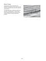
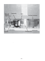
Evaporator Fan
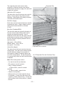
Evaporator Fan Adjustment
The position of the fan blade in relation to the
shroud is critical. Refer to graphic for
specifications.
5/16" ± 0.03
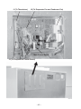
If the fan shorts, it will damage the main control
board. If the resistor on the main control board
is burnt, you must replace the fan and the board
(see photo).
Blade tip
1.0" ± 0.05 Target
Orifice
Air
Flow
Airflow
Motor
GEA01149
Evaporator and Condenser Fan Resistors
Evaporator Fan Resistor
GEA01140
Condenser Fan Resistor
GEA01141
Bad Evaporator Fan Resistor
– 19 –
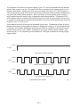
The evaporator fan utilizes a permanent magnet, 4-pole, DC motor that operates at three different
speeds: high, medium, and low. The speed of the fan is controlled by the voltage output from the
primary control board. Voltage output from the control board to the fan is 12.6 VDC; however, in
order to regulate the speed of the fan, the control board uses pulse width modulation (PWM) during
low speed and medium speed operation. When operating in low and medium speed, voltage is
sent in pulses (much like a duty cycle) as opposed to an uninterrupted flow. This pulsing of 12.6
VDC produces effective voltage being received at the motor, which is the equivalent to a reduction
in voltage. Fan speed will be selected and maintained by the control board regulating the length and
frequency of the 12.6-VDC pulse.
One complete revolution of the motor is comprised of all 4 poles. To determine the rpm of the fan:
Measure the frequency being applied to the motor. Multiply this number by 15 (60 seconds divided
by 4 poles). For example, a frequency measurement of 200 Hz multiplied by 15 would show a fan
speed of 3000 rpm (15 x 200 = 3000). Temperature may cause some fan speed variation. Fan
speed may vary +/- 5%, depending on the temperature, with higher temperatures causing slightly
higher speeds.
12 VDC
12 VDC
0 VDC
High Speed (12 VDC measured)
12VDC
8 VDC
0 VDC
Medium Speed (8 VDC measured)
12 VDC
4 VDC
0 VDC
Low Speed (4 VDC measured)
EVAPORATOR FAN SPEEDS
– 20 –
GEA01139
The evaporator fan motor uses a 4-wire
connection, utilizing a common wire (white),
feedback/rpm wire (blue), supply wire (red), and
a signal wire (yellow).
Evaporator Fan
White Wire (DC Common)
The white wire is the DC common wire used for
testing. During repairs, DC polarity must be
observed. Reversing the DC polarity will cause
a shorted motor and/or board.
Connector (To Main Control Board)
Red Wire (Supply)
Each motor uses an internal electronic controller
to operate the motor. Supply voltage from the
main control board remains at a constant
12 VDC.
Blue Wire (Feedback/RPM)
The blue wire feeds rpm (speed) information to
the main control board, allowing the board to
maintain consistent fan speeds. Loss of
feedback from the blue wire will result in the fan
accelerating to maximum speed. Measure the
fan rpm using the frequency between the blue
and white wires.
High speed - 195 to 200 Hz
Medium speed - 145 to 160 Hz
Low speed - 70 to 85 Hz
Evaporator Fan Connector
Yellow Wire (Signal)
The yellow wire is the input wire from the main
control board. The main control board provides
4.6 VDC effective voltage for low speed, 8.1
VDC effective voltage for medium speed, and
12.6 VDC for high speed. The fan will operate
in low speed only when the fresh food thermistor
is satisfied.
J2 (To Evaporator Fan and Condenser Fan)
Note: When testing these motors:
• You cannot test with an ohmmeter.
• DC common is not AC common.
• Verify 2 voltage potentials:
a. Red to white - power for internal
controller.
b. Yellow to white - power for fan.
• Observe circuit polarity.
• Motors can be run for short periods using a
9-volt battery. Connect the white wire to the
negative (-) battery terminal only. Connect the
red and yellow wires to the positive (+) battery
terminal.
Main Control Board
– 21 –
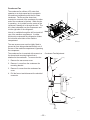
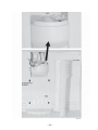
Condenser Fan
The condenser fan utilizes a DC motor that
operates on a single speed and is mounted in
the machine compartment with the No-Clean
condenser. The fan and fan shroud are
mounted on one end of the condenser, the other
end of the condenser is blocked. When the fan
is operating, air is pulled from the center of the
condenser, drawing air in through the coils. The
air is then exhausted over the compressor and
out the right side of the refrigerator.
Inlet air is available through the left front and left
rear of the machine compartment. A rubber
divider strip underneath the refrigerator divides
the inlet and outlet sides of the machine
compartment.
Rear
Baffle
Front
GEA01152
The rear access cover must be tightly fitted to
prevent air from being exhausted directly out of
the rear of the machine compartment, bypassing
the compressor.
The condenser fan is mounted with screws to a
fan shroud and mounting bracket that is
attached to the condenser. To remove the fan:
Condenser Fan Adjustment
1/2"
Housing
1. Remove the rear access cover.
2. Remove 1 screw from the condenser fan
mounting bracket.
3. Remove 2 screws from the condenser fan
cover.
Fan
4. Pull the fan out and disconnect the electrical
connector.
0.375"
Motor
Airflow
Air Flow
Bracket
0.50" ± 0.05
GEA01148
– 22 –
defrosts. If the doors are opened frequently
and/or for long periods of time, the compressor
run time between defrosts will be reduced to as
little as 8 hours.
DEFROST SYSTEM
Adaptive Defrost
Adaptive Defrost can be described as a defrost
system that adapts to a refrigerator’s
surrounding environment and household usage.
Adaptive Defrost (Pre-chill Operation)
Unlike conventional defrost systems that use
electromechanical timers with a fixed defrost
cycle time, Adaptive Defrost utilizes an
intelligent, electronic control to determine when
the defrost cycle is necessary. In order to
accomplish the correct defrost cycle time, the
main control board monitors the following
refrigerator operations:
•
Length of time the refrigerator doors were
open since the last defrost cycle
•
Length of time the compressor has run
since the last defrost cycle
•
Amount of time the defrost heaters were on
in the last defrost cycle
F
R
E
E
Z
E
R
A
I
R
PRE-CHILL MODE
F˚ / C˚
25˚ / -4˚
20˚ / -7˚
15˚ / -9˚
10˚ / -12˚
5˚ / -15˚
T
E
0˚ / -18˚
M
P
-5˚
/ -21˚
E
R
A -10˚ / -23˚
T
U -15˚ / -26˚
R
E
S -20˚ / -29˚
08:00
09:00
10:00
11:00
12:00
13:00
14:00
15:00
16:00
17:00
18:00
Pre-Chill Defrost
Adaptive Defrost is divided into 5 separate
cycles. Those operations are:
•
Cooling Operation
•
Pre-Chill Operation
•
Defrost Heater Operation
•
Dwell Period
•
Post Dwell
When the main control board determines that
defrost is necessary, it will force the refrigerator
into a continuous cool mode (pre-chill). During
pre-chill, the freezer temperature may be driven
below the set point. However, the fresh food
temperature will be regulated by the evaporator
fan running at low speed. Pre-chill will last for 2
hours. These models do not have a defrost
holdoff.
Adaptive Defrost (Defrost Heater
Operation)
After 2 hours of pre-chill operation, the main
control board turns off the compressor,
condenser fan, and evaporator fan.
(See Pub. #31-9062 for more information on
Adaptive Defrost.)
Adaptive Defrost (Cooling Operation)
During the cooling operation, the main control
board monitors door opening (fresh food and
freezer doors) and compressor run times. The
board counts the time the doors are open. It
reduces the length between defrosts by 210
seconds (multiplication factor) for each second
that each door is open (if both doors are open,
it reduces it by twice the amount). The
multiplication factor reduces compressor run
time. If the doors are not opened, the
compressor will run up to 60 hours between
During defrost operation, the main control board
monitors the evaporator temperature using
evaporator thermistor inputs. Typically, the
evaporator thermistor will sense a temperature
of 65°F within 25 minutes. When the thermistor
senses 65°F, the main control board will
terminate defrost heater operation. Maximum
defrost cycle (heater on) time is 45 minutes
(main control board time out).
The defrost system is protected by a defrost
termination thermostat (switch). The thermostat
opens when the evaporator temperature raises
to 140°F and closes when the evaporator
temperature lowers to 110°F.
– 23 –
Adaptive Defrost (Dwell Period)
After defrost heater operation has been
terminated by the main control board, a 5minute dwell period occurs. During this period,
the compressor, condenser fan, and the
evaporator fan remain off. The remaining frost
melting from the evaporator will continue to drip
and drain so that prior to the cooling operation,
the evaporator will be totally clear of any
moisture. After the 5-minute dwell period, the
unit goes into post dwell.
Adaptive Defrost (Post Dwell)
The post dwell period is designed to cool the
evaporator before circulating air within the
refrigerator. This prevents any residual heat on
the evaporator from being distributed in the
freezer. During this period, the compressor is on
and the condenser fan is on, but the evaporator
fan is off. Post dwell will last 15 minutes or until
the evaporator temperature reaches 30°F on
these models.
Normal Operating Characteristics That
Are Different from Previous Models
•
Evaporator fan running without compressor
or condenser fan.
•
Post Dwell (Adaptive Defrost), compressor,
and condenser fan on with evaporator fan off
after defrost cycle.
•
Liner Protection Mode, fan comes on when
the doors are open for 3 minutes.
•
Evaporator fan and compressor can run
continuously for 2 hours (Adaptive Defrost).
•
Different sound levels can be heard when
the fan changes speed.
•
Response time for drastic temperature
change is 2 to 10 minutes. The main control
board will only respond to 8 degrees
(Fahrenheit) of temperature change per
minute as determined by resistance of
sensor.
Abnormal Operating Characteristics
(Incorrect Operation)
•
Rapid fan speed changes, fan takes at least
1 minute to change speeds.
•
Compressor running without the condenser
fan. The compressor and condenser fan
should always run at the same time.
Liner Protection Mode
The liner protection mode will activate if either of
the doors have been open for 3 minutes. This
mode will start the evaporator fan on high
speed.
This mode is controlled by 2 timers. Timer 1
monitors door-open time. A 3-minute door-open
count begins when the door is opened. If 3
minutes elapse before the door is closed, the
liner protection mode will become active. Once
the door is closed, timer 1 resets and liner
protection mode goes into standby. In standby,
normal fan and damper operations resume and
timer 2 begins a 3-minute door-closed count. If
3 minutes elapse without a door opening, liner
protection mode will completely deactivate. If a
door is opened within the timer 2 door-closed
count, the remaining time in the door-closed
count will be deducted from the timer 1 dooropen count.
– 24 –
Defrost Heater
The defrost heater is a single-tube, radiant
heater. It is held in place by 2 tabs on the
evaporator (1 on each side) and by 2 ceramic
and wire supports.
The ceramic and wire supports prevent the
heater from sagging and touching the metal
drain pan if the glass is broken.
Heater Supports
Defrost Drain Probe
Evaporator Thermistor
The evaporator thermistor is mounted on the
upper right side of the evaporator. The defrost
cycle will terminate when the main control board
detects 65°F from the evaporator thermistor.
The main control board must sense 65°F in less
than 45 minutes, or the defrost cycle will time
out. Normal defrost time is 25 minutes or less,
not including the 5-minute dwell or post dwell
periods.
Defrost Heater Supports
Defrost Overtemperature Thermostat
Defrost Overtemperature Thermostat
The defrost overtemperature thermostat
(bimetal switch) is mounted on the evaporator
and provides overtemperature protection during
defrost. This thermostat will open at 140°F and
will close at 110°F.
Note: The main control board will not know if
the heater does not come on due to a broken
heater, open defrost overtemperature
thermostat, or an open wiring harness. The
defrost heater is controlled by maximum time on
the main control board or temperature at the
evaporator thermistor.
Evaporator Thermistor
– 25 –
Defrost Probes
A defrost drain probe is attached to the
evaporator and extends into the drain opening.
This probe transfers heat to the drain opening
during defrost.
Two additional defrost probes are attached to
the sides of the evaporator. These probes
extend upward between the freezer wall and
evaporator sides to assist the defrosting
process.
Evaporator
Defrost Drain Probe
– 26 –
CONTROL SYSTEM
Control Console
The control console, located at the top front of
the fresh food compartment, contains an
encoder (knob version) or a touch panel.
Remove the control console by removing 4 (1/4in.) hex head screws. Use care when
disconnecting the wire connectors from the
encoder or touch panel.
5
9 IS COLDEST
ADJUST FREEZER TEMP
ADJUST FREEZER TEMP
ACTIVATE LOCK
WARMER
HOLD
3 SECS
COLDER
5
ADJUST REFRIGERATOR TEMP
ADJUST REFRIGERATOR TEMP
COLDER
WARMER
9 IS COLDEST
9 IS COLDEST
Temperature Encoder
The temperature encoder (knob version)
receives switched DC voltage from the main
control board. There are two possible failure
modes - both are open circuits.
An open circuit from the supply side results in
the refrigerator defaulting to midpoint. The
supply side consists of pins 1 and 2.
An open circuit from the return side results in
inconsistent run mode. The return side consists
of pins 3 and 6.
Failure of the fresh-food-only side results in the
fresh food defaulting to midpoint.
Failure of the freezer side results in the freezer
defaulting to midpoint.
Temperature Touch Panel
The temperature touch panel receives switched
DC voltage from the main control board.
ADJUST FREEZER TEMP
ACTIVATE LOCK
WARMER
HOLD
3 SECS
COLDER
Failure of input results in default to most recent
setting. Input consists of pins 2 to 3.
Failure of output results in erratic control.
Output consists of pin 1.
– 27 –
9 IS COLDEST
ADJUST REFRIGERATOR TEMP
COLDER
9 IS COLDEST
WARMER
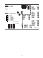
Control Board
The main control board, located behind a panel at the rear of the refrigerator, manages the
operation of the refrigerator by calculating response from various inputs.
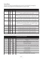
C ON TR OL B OAR D PIN D EFIN ITION S
C ON N EC TOR
PIN
IN PU T
OU TPU T
FU N C TION
J1
1
VD C
Feedback of fresh food thermi stor value. Thermi stor i s NTC , when temperature drops,
resi stance value i ncreases, causi ng return voltage reducti on. Thi s value i s used to cycle
fresh food fan (when used), evaporator fan, compressor, and condensor fan. Feedback i s
fi ltered to respond to 8 degrees of change per mi nute.
J1
2
VD C
Feedback of second fresh food thermi stor value (when used). Thermi stor i s NTC , when
temperature drops, resi stance value i ncreases, causi ng return voltage reducti on. Thi s value
i s used to cycle fresh food fan (when used), evaporator fan, compressor, and condensor
fan. Feedback i s fi ltered to respond to 8 degrees of change per mi nute.
J1
3
VD C
Feedback of freezer thermi stor value. Thermi stor i s NTC , when temperature drops,
resi stance value i ncreases, causi ng return voltage reducti on. Thi s value i s used to cycle
evaporator fan, compressor, and condensor fan, and wi ll not cycle fresh food fan (when
used). Feedback i s fi ltered to respond to 8 degrees of change per mi nute.
VD C
Feedback of evaporator thermi stor value. Thermi stor i s NTC , when temperature drops,
resi stance value i ncreases, causi ng return voltage reducti on. Thi s thermi stor value i s used
to cycle the heater on duri ng defrost when temperature i s below defrost value and off when
the temperature i s above defrost value. Thi s value i s also read duri ng power-up to
determi ne i f refri gerator goes i nto pulldown mode or cycle conti nuati on. Feedback i s
unfi ltered, responds i mmedi ately.
J1
4
J1
5
J1
6
VD C
Selecti on pi n that, when connected i n combi nati on wi th other personali ty pi ns, determi nes
model and programmi ng used. Reads combi nati on on power-up only.
J1
7
VD C
Selecti on pi n that, when connected i n combi nati on wi th other personali ty pi ns, determi nes
model and programmi ng used. Reads combi nati on on power-up only.
J1
8
VD C
Selecti on pi n that, when connected i n combi nati on wi th other personali ty pi ns, determi nes
model and programmi ng used. Reads combi nati on on power-up only.
J1
9
VD C
Selecti on pi n that, when connected i n combi nati on wi th other personali ty pi ns, determi nes
model and programmi ng used. Reads combi nati on on power-up only.
VD C
Provi des 5 VD C for thermi stors and personali ty pi ns on J1.
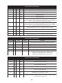
CONTROL BOARD PI N DEFI NI TI ONS
CONNECTOR PI N
I N PU T
OUTPUT
FUNCTI ON
J2
1
Hz
Feedback from evaporator fan. This feedback frequency is used to control the PWM for
fan speeds.
J2
2
VD C
Selection pin that, when connected in combination with other personality pins, determines
model and programming used.
J2
3
VD C
Fan common - VDC ground
J2
4
VD C
Output to evaporator fan for motor operation. Effective voltage is determined by PWM.
J2
5
VD C
Output to condensor fan for motor operation. Effective voltage is determined by PWM,
speed set in EEPROM.
J2
6
VD C
Output to fresh food fan (when used) for motor operation. There is no feedback for PWM
used on fresh food fan.
J2
7
VD C
Output to CustomCool fan (when used) for motor operation. There is no feedback for
PWM used on QuickChill fan.
J2
8
VD C
Provides 12 VDC supply voltage to all fans, constant voltage.
– 28 –
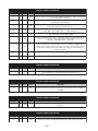
C ON TR OL B OAR D PIN D EFIN ITION S
C ON N EC TOR
PIN
J3
IN PU T
OU TPU T
FU N C TION
1
VD C
D amper (when used).
J3
2
VD C
D amper (when used).
J3
3
VD C
D amper (when used).
J3
4
VD C
D amper (when used).
J3
5
VD C
Fresh food output to temperature encoder. Loss of output causes fresh food compartment
to operate at mi dpoi nt setti ng. Energi zed every 50 mi lli seconds, then energi zes pi n 6.
Reads pattern on pi ns 7 - 10 to see what posi ti on fresh food encoder i s i n. No si gnal from
pi ns 7 - 10 results i n errati c fresh food and freezer operati on.
J3
6
VD C
Freezer output to temperature encoder. Loss of output causes freezer compartment to
operate at mi dpoi nt setti ng. Energi zed every 50 mi lli seconds after pi n 5 i s energi zed.
Reads pattern on pi ns 7 - 10 to see what posi ti on freezer encoder i s i n. No si gnal from
pi ns 7 - 10 results i n errati c fresh food and freezer operati on.
J3
7
VD C
Input from temperature encoder. Loss of i nput results i n errati c operati on.
J3
8
VD C
Input from temperature encoder. Loss of i nput results i n errati c operati on.
J3
9
VD C
Input from temperature encoder. Loss of i nput results i n errati c operati on.
J3
10
VD C
Input from temperature encoder. Loss of i nput results i n errati c operati on.
CONTROL BOARD PIN DEFINITIONS
CONNECTOR PIN
INPUT
OUTPUT
Digital
Digital
Communication Communication
FUNCTION
J4
1
Two-way digital communication between control and control board.
J4
2
VD C
12-VDC supply.
J4
3
VD C
DC common.
J4
4
VD C
Used on some dispener models to activate water, cubed and/or crushed ice.
J4
5
VD C
Used on some dispener models to activate water, cubed and/or crushed ice.
No signal on pin 4 and no signal on pin 5 is off position.
No signal on pin 4 with signal on pin 5 is crushed selection.
Signal on pin 4 and no signal on pin 5 is cubed selection.
Signal on pin 4 and signal on pin 5 is water selection.
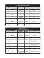
CONTROL BOARD PI N DEFI NI TI ONS
CONNECTOR
PI N
J5
I N PU T
OUTPUT
FUNCTI ON
1
VD C
CustomCool damper (when used).
J5
2
VD C
CustomCool damper (when used).
J5
3
VD C
CustomCool damper (when used).
J5
4
VD C
CustomCool damper (when used).
J5
5
VD C
Input voltage to J5 pin connections: + 5 VDC.
J5
6
VD C
Feedback of CustomCool thermistor value. Thermistor is NTC, when temperature drops,
resistance value increases, causing a reduction in return voltage. This value is used to
cycle CustomCool fan (when used).
– 29 –
CONTROL BOARD PIN DEFINITIONS
CONNECTOR
PIN
J7
OUTPUT
FUNCTION
1
VAC
Output to auger motor circuit on models equipped with dispenser. Will not provide output
when no input is present at pin 4.
J7
2
VAC
Output to cube solenoid circuit on models equipped with dispenser. Will not provide output
when no input is present at pin 4.
J7
3
VAC
Output to water valve solenoid circuit on models equipped with water dispenser. Will not
provide output when no input is present at pin 7.
J7
4
J7
5
J7
6
J7
7
J7
8
J7
9
INPUT
Interlock circuit. Recieves input from freezer door switch when door is closed (switch
closed). Will not allow output to pins 1 or 2 when input present.
VAC
VAC
L1 output to CustomCool heater when equipped.
VAC
Receives L1 input from fresh food door switch when switch closes (door open). This input
is used for fan power door control, liner protection mode calculations, door alarm
calculations, and adaptive defrost calculations.
VAC
Receives L1 input from freezer door switch when switch closes (door open). This input is
used for fan power door control, liner protection mode calculations, adaptive defrost
calculations, door alarm calculations, and some door interlock functions. Switch must be
closed in door closed position (switch depressed) for dispenser light and duct door
magnet to energize.
VAC
AC neutral in
CONTROL BOARD PIN DEFINITIONS
CONNECTOR
PIN
J8
1
INPUT
OUTPUT
FUNCTION
VAC
Switched L1 output to compressor circuit. A timer counts how long circuit is energized and
uses this information to determine when the next defrost will occur.
CONTROL BOARD PIN DEFINITIONS
CONNECTOR
PIN
J9
1
INPUT
OUTPUT
FUNCTION
VAC
Switched L1 voltage to the defrost circuit - 120 VAC. A timer counts how long this circuit is
energized and uses this information to determine if the next defrost cycle is adaptive or
nonadaptive.
CONTROL BOARD PIN DEFINITIONS
CONNECTOR
PIN
INPUT
J11
1
VAC
OUTPUT
FUNCTION
Constant L1 voltage to control board circuits - 120 VAC input potential for switched L1
terminals.
CONTROL BOARD PIN DEFINITIONS
CONNECTOR
PIN
J1 2
1
INPUT
OUTPUT
FUNCTION
VAC
Switched L1 voltage to the drain pan heater for Monogram models (when used).
– 30 –
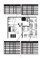
Main C ontrol B oard Locator Table
J1 C onnector (Low -Voltage Side)
Pin
Wire C olor
C omponent
Termination
Input/
Output
Pin-to-Pin Voltage R eading
1
Blue/Red
Fresh food
thermi stor
Input
J1 pi n 1 to pi n 5 = 2.8 to 3.5
VD C
2
Not used
Not used
Not used
Not used
3
Red/Whi te
Freezer thermi stor
Input
J1 pi n 3 to pi n 5 = 2.8 to 3.5
VD C
4
Whi te
Evaporator
thermi stor
Input
J1 pi n 4 to pi n 5 = 2.8 to 3.5
VD C
5
Blue
Thermi stor supply
voltage (5 VD C )
Output
J1 pi n 5 to J7 pi n 9 = 5 VD C
6
Not used
Not used
Not used
Not used
7
Blue
Thermi stor supply
voltage (5 VD C )
Output
J1 pi n 7 to J7 pi n 9 = 5 VD C
Main C ontrol B oard
J2 C onnector (Low -Voltage Side)
Pin
Wire C olor
C omponent
Termination
Input/
Output
Pin-to-Pin Voltage R eading
1
Blue
Evaporator fan
tachometer
Input
J2 pi n 1 to pi n 3 = 6.3 VD C
2
Not used
Not used
Not used
Not used
3
Whi te
Fan common
C ommon
J2 pi n 3 to pi n 8 = 12 VD C
4
Yellow/Black
Evaporator fan
Output
J2 pi n 4 to pi n 3 = 12.6 VD C
(hi gh), 8.1 VD C (med.),
4.6 VD C (low)
5
Yellow
C ondenser fan
Output
J2 pi n 5 to pi n 3 = 13.4 VD C
(condenser fan i s si ngle
sp e e d )
6
Not used
Not used
Not used
Not used
7
Not used
Not used
Not used
Not used
8
Red
Fan supply voltage
(12 VD C )
Output
J2 pi n 8 to pi n 3 = 12 VD C
– 31 –
Main Control Board
J3 Connector (Low -Voltage Side)
Pin
Wire Color
Component
Termination
5
Blue/Yellow
Temperature control
panel
6
White/Brown
Temperature control
panel
7
Red/Black
Temperature control
panel
8
Black
Temperature control
panel
9
Red
Temperature control
panel
10
Red
Temperature control
panel
Input/
Output
Pin-to-Pin Voltage Reading
M ain Control Board
J7 Connector (Low -Voltage Side)
Pin
Wire Color
Component
Termination
I nput/
Output
Pin-to-Pin Voltage Reading
6
Purple
Fresh food door light
switch
Input
J7 pin 6 to J7 pin 9 = 120 VAC
(FF door open)
7
Red
Freezer door light switch
Input
J7 pin 7 to J7 pin 9 = 120 VAC
(FZ door open)
8
Not used
Not used
Not used
Not used
9
Orange
Neutral
Neutral
Neutral
– 32 –
– 33 –
M ain Control Board
J7 Connector (Low-Voltage Side)
Main Control Board
J3 Connector (Low -Voltage Side)
Pin
Wire Color
Component
Termination
Input/
Output
Pin-to-Pin Voltage Reading
6
Purple
Fresh food door light
switch
Input
J7 pin 6 to J7 pin 9 = 120 VAC
(FF door open)
7
Red
Freezer door light switch
Input
J7 pin 7 to J7 pin 9 = 120 VAC
(FZ door open)
Pin
Wire Color
Component
Termination
5
Blue/Yellow
Temperature control
panel
6
White/Brown
Temperature control
panel
7
Red/Black
Temperature control
panel
8
Not used
Not used
Not used
Not used
8
Black
Temperature control
panel
9
Orange
Neutral
Neutral
Neutral
9
Red
Temperature control
panel
10
Red
Temperature control
panel
Main Control Board
J2 Connector (Low -Voltage Side)
Input/ Pin-to-Pin Voltage Reading
Output
Main Control Board Locator Table
J1 Connector (Low -Voltage Side)
Pin
Wire Color
Component
Termination
Input/
Output
Pin-to-Pin Voltage Reading
1
Blue
Evaporator fan
tachometer
Input
J2 pin 1 to pin 3 = 6.3 VDC
2
Not used
Not used
Not used
Not used
3
White
Fan common
Common
J2 pin 3 to pin 8 = 12 VDC
4
Yellow/Black
Evaporator fan
Output
J2 pin 4 to pin 3 = 12.6 VDC
(high), 8.1 VDC (med.),
4.6 VDC (low)
5
Yellow
Condenser fan
Output
J2 pin 5 to pin 3 = 13.4 VDC
(condenser fan is single
sp e e d )
6
Not used
Not used
Not used
Not used
7
Not used
Not used
Not used
Not used
8
Red
Fan supply voltage
(12 VDC)
Output
J2 pin 8 to pin 3 = 12 VDC
Pin
Wire Color
Component
Termination
Input/
Output
Pin-to-Pin Voltage Reading
1
Blue/Red
Fresh food
thermistor
Input
J1 pin 1 to pin 5 = 2.8 to 3.5
VD C
2
Not used
Not used
Not used
Not used
3
Red/White
Freezer thermistor
Input
J1 pin 3 to pin 5 = 2.8 to 3.5
VD C
4
White
Evaporator
thermistor
Input
J1 pin 4 to pin 5 = 2.8 to 3.5
VD C
5
Blue
Thermistor supply
voltage (5 VDC)
Output
J1 pin 5 to J7 pin 9 = 5 VDC
6
Not used
Not used
Not used
Not used
7
Blue
Thermistor supply
voltage (5 VDC)
Output
J1 pin 7 to J7 pin 9 = 5 VDC
– 34 –
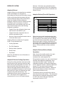
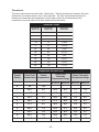
Thermistors
This main control board uses input from 3 thermistors. These thermistors are located in the fresh
food section, the freezer section, and on the evaporator. The main control board monitors the
thermistors to determine the temperature in these areas of the unit and determines which
components to run and when to run them, based on this information.
Thermistor Values
Temperature
Degrees (C)
Temperature
Degrees (F)
Resistance
in Kilo-ohms
-40
-40
166.8 kΩ
-30
-22
88 kΩ
-20
-4
48.4 kΩ
-10
14
27.6 kΩ
0
32
16.3 kΩ
10
50
10 k Ω
20
68
6.2 kΩ
30
86
4 kΩ
40
104
2.6 kΩ
50
122
1.8 kΩ
60
140
1.2 kΩ
Temperature Set Point Chart
Control
Setting
Fresh Food
Compartment
Freezer
Compartment
Fresh Food
Thermistor
Temperature Range
Minimum
Maximum
Freezer Thermistor
Temperature Range
Minimum Maximum
0
Off
Off
1
44°F
6°F
43°F
45°F
1°F
11°F
2
40°F
4°F
39°F
41°F
-1°F
9°F
3
39°F
3°F
38°F
40°F
-2°F
8°F
4
38°F
1°F
37°F
39°F
-4°F
6°F
5
37°F
0°F
36°F
38°F
-5°F
5°F
6
36°F
-1°F
35°F
37°F
-6°F
4°F
7
35°F
-3°F
34°F
36°F
-8°F
2°F
8
35°F
-4°F
34°F
36°F
-9°F
1°F
9
34°F
-6°F
33°F
35°F
-11°F
-1°F
– 35 –
ELECTRICAL SYSTEM
Door Switches
The door switch (fresh food or freezer) closes when the door is open. When the door switch is
closed, L1 is provided to the compartment light(s). The main control board receives L1 input on
pin 6, J7 when the fresh food door switch is closed (door open). The main control board receives
L1 input on pin 4, J7 when the freezer door switch is closed (door open).
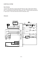
Schematic
TEMPERATURE CONTROL BOARD IN
CONTROL HOUSING, FF COMPARTMENT
TEMPERATURE
CONTROL
5
PURPLE
J6-6
ORANGE
J4-1
TAB 2
ORANGE
DEFROST
THERMOSTAT
ORANGE
FRESH FOOD LIGHT
FF SWITCH
J6-7
RED
– 36 –
ORANGE
RED
J6-4
FREEZER LIGHT
FZ SWITCH
BROWN
TAB 4
BROWN
ORANGE
ORANGE
BROWN
(SEE INDIVIDUAL
DIAGRAM)
WHITE
WHITE
WHITE
ORANGE
WATER VALVE
ORANGE
ICE MAKER
ORANGE
(SEE INDIVIDUAL DIAGRAM)
BROWN
J1-1
BLUE/RED
PINK
PURPLE
THERMISTOR FF1
BLUE/RED
3
1
PURPLE
J1-5
RED/WHITE
CAPACITOR
DEFROST HEATER
BROWN
J6-9
RED/WHITE
J1-4
THERMISTOR FZ.
BLUE/WHITE
J1-3
BLUE
BLUE
+5V BLUE
THERMISTOR EVAP.
RELAY
BLUE
J1-7
EVAP. FAN
MOD 2
BLUE
J4-2
(SEE
INDIVIDUAL
DIAGRAM)
WHITE
4
J4-3
J2-4
WHITE
BLUE
RED
YELLOW
WHITE
RED
YELLOW
BLUE (RPM)
J2-1
WIHTE (COMM)
J2-3
YELLOW
YELLOW/BLACK
ORANGE
COMPRESSOR
MAIN CONTROL PWB
+ 12V RED
BLACK
OVERLOAD
J2-8
RED/BLACK
J2-5
WHITE/BROWN
COND. FAN
ORANGE
6
J3-1
ORANGE
J3-3
TAB 1
J3-5
BLUE/YELLOW
(SEE
INDIVIDUAL
DIAGRAM)
ORANGE
BROWN
(SEE INDIVIDUAL DIAGRAM)
SMART TROLLEY
1
2
3
ORANGE
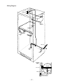
Wiring Diagram
GREEN/YELLOW
FREEZER
LAMP
RED
ORANGE
ORANGE
TO
ICE MAKER
WHITE
DEFROST
THERMOSTAT
BROWN
ORANGE
PINK
BLUE
DEFROST
THERMOSTAT
RED
BROWN
FREEZER
LIGHT SWITCH
PURPLE
PURPLE
ORANGE
BROWN
FRESH FOOD
LIGHT SWITCH
FRESH FOOD
LAMP
ORANGE
PURPLE
ORANGE
POWER CORD
BLACK
ORANGE
TO MACHINE
WIRING
WHITE
ICE MAKER
VALVE
TO CABINET
WIRING
GREEN/YELLOW
OVERLOAD
ORANGE
C
S
1
WHITE
R
2
BLACK
WHITE
RUN CAPACITOR
– 37 –
RELAY
ORANGE
REFRIGERATION SYSTEM
Condenser Loop
The major components of the refrigeration
system are a reciprocating-type compressor,
condenser, condenser loop, dryer, and a spinefin evaporator. These components, except for
the condenser loop, are all replaceable
separately.
The condenser loop, made of 5/32-in. O.D.
copper tubing, is foamed in place behind the
breaker frame and across the mullion. It is not
accessible for replacement. The tubing is
routed from the rear of the machine
compartment forward to the mullion, across the
mullion, across the right side of the freezer
compartment, across the top of the freezer
compartment, down the right side of the freezer,
and back to the rear of the machine
compartment. The outlet of the condenser loop
is connected to the dryer inlet.
Compressor
The compressor is a reciprocating type. Refer
to the mini-manual for the BTU/hour rating and
the compressor capacity test specification.
A 1/4-in. O.D. copper process tube is provided
for access to the low-pressure side of the
refrigeration system.
The channel that the compressor is mounted in
must be disengaged from the cabinet to remove
the compressor.
Note: Capillary tube must be clipped to
compressor suction line near the dryer. If
capillary tube is not clipped to suction line, a
knocking noise may occur during compressor
operation.
Dryer
The dryer is positioned vertically in the center of
the machine compartment. A 1/4-in. O.D.
copper process tube, connected to the inlet of
the dryer, provides access to the high-pressure
side of the refrigeration system. The capillary is
connected to the outlet of the dryer.
Replacement of filter dryer requires additional
refrigerant when installed (0.5 oz).
Note: The dryer is wrapped in mastic as a
sound reducer and foam tape for shipping
purposes. When replacing the dryer, the mastic
must be reinstalled to reduce sound. It is not
necessary to reinstall the foam tape.
Refer to the compressor replacement
instructions included with the replacement
compressor.
No-Clean Condenser
The Condenser is a No-Clean, “jelly roll” style
condenser made of 3/16-in. O.D. steel tubing.
The outlet of the condenser is connected to a
copper jumper tube that is connected to the inlet
of the condenser loop. The No-Clean
condenser is accessed from the rear of the
cabinet and is designed to be more tolerant of
lint buildup than previous condensers. The
consumer, in normal operating conditions, will
never have to clean the condenser. If
necessary, only an ordinary appliance brush is
used. Air is drawn in from the outside diameter
of the condenser. A condenser fan baffle is
located at the rear to direct airflow through the
condenser. Functionally, the condenser does
the same job as previous models. Air is drawn
into the condenser from the front left and rear
left of the cabinet. Air exits only from the right
side of the cabinet.
Evaporator
The spine-fin evaporator, made of aluminum
tubing and formed into hairpin spirals, is located
below the evaporator fan housing at the back of
the freezer compartment. The replacement
evaporator is furnished without a heat
exchange.
Evaporator (Soldering Method)
1. Recover the refrigerant.
2. Remove the evaporator cover.
3. Remove the defrost thermostat.
4. Remove the defrost heater.
5. Disconnect the ground wire from the
evaporator and position all wiring to allow for
evaporator removal.
– 38 –
4. Remove the defrost heater.
6. Remove the 2 screws that hold the
evaporator to the cabinet.
Caution:
• If desoldering the evaporator, heat shield,
P/N WR49X10025, must be used to
prevent damage to freezer liner.
• Protect wiring from heat during
desoldering and resoldering.
• To prevent damage to the capillary tube,
the capillary tube must be desoldered
first.
7. Desolder the capillary tube from the
evaporator.
8. Desolder the suction line. Use a pair of pliers
to hold the evaporator.
9. Remove the evaporator.
10. Using a file, score the capillary tube just above
the old solder and break the solder-covered
section off. This will help prevent the capillary
tube from becoming plugged when
resoldering.
11. Position the new evaporator in the cabinet.
Insert the suction line and capillary tube into
the evaporator.
12. Solder the suction line to the evaporator
using silfos.
13. Solder the capillary tube to the evaporator
using silfos.
Note: Heat probe assists in defrosting drain.
During assembly, probe must be installed on
evaporator and in drain to prevent drain from
freezing closed.
14. Install a replacement dryer.
15. Evacuate and recharge the system using
currently accepted procedures.
5. Disconnect the ground wire from the
evaporator and position all wiring to allow for
evaporator removal.
6. Remove the 2 screws that hold the
evaporator to the cabinet.
Caution: Tubing must be clean and free from
burrs when using LOKRING.
Note: LOKRING connector, P/N WR97X10021
must be used. Two LOKRING connectors P/N
WR97X10021 are required.
7. Replace the evaporator using the LOKRING
method (see Pub #31-9067).
• Cut the copper lines of the old evaporator
as close as possible to the aluminum
evaporator tubes.
• Cut the copper lines of the new evaporator
1-1/8 in. from the edge of the aluminum
evaporator tubes.
• Defrost thermostat can be moved from the
horizontal part of the copper line to the
vertical part, just above the bend.
Note: Heat probe assists in defrosting drain.
During assembly, probe must be installed on
evaporator and in drain to prevent drain from
freezing closed.
8. Install a replacement dryer.
9. Evacuate and recharge the system using
currently accepted procedures.
Refrigerant Charge
The refrigerant used in this model is type
R134a. Refer to the mini-manual or model tag
for the exact refrigerant charge quantity.
Evaporator (LOKRING Method)
1. Recover the refrigerant.
2. Remove the evaporator cover.
3. Remove the defrost thermostat.
– 39 –
COMPONENT AND CONNECTOR LOCATOR VIEWS
Evaporator Fan
Evaporator Fan Connector
Freezer
Thermistor
Icemaker Connector
Evaporator
Thermistor
Defrost
Probe
Defrost
Overtempertaure
Thermostat
Defrost
Heater
Evaporator
Defrost Heater
Support
Defrost Drain Probe
– 40 –
Fresh Food
Door Switch
Temperature Control
Fresh Food
Thermistor
Fresh Food Compartment
– 41 –
J1 (To Thermistors)
J2 (To Evaporator Fan and Condenser Fan)
J7
Main Control Board
J3 (To Temperature Control Board)
– 42 –
– 43 –
Compressor
Relay and
Overload
(Under Cover)
Dryer
No-Clean Condenser
Condenser Fan
Capacitor
– 44 –
Fresh Food Warm - Freezer Warm
Basic refrigeration checks:
Door gasket seal OK?
Door switch - light turning off with
door closed?
All OK?
Repair as
necessary.
NO
YES
Reset electronics by unplugging
refrigerator for 15 seconds then
plug back in.
Is the evaporator fan running?
NO
Go to Evaporator
Fan Not Running
flowchart.
NO
Go to Condenser Fan
Not Running flowchart.
NO
Go to Compressor Not Running
flowchart.
NO
Look for blockage
at vents or heavy
frost on evaporator
cover.
YES
Is the condenser fan running?
YES
Is the compressor running?
YES
Is the airflow in the fresh food
compartment normal?
Blockage
Remove blockage from
evaporator cover vent
area.
YES
Verify thermistors are within
proper range.
Is the resistance within range?
NO
Check wiring
connections. If OK,
replace thermistor.
YES
Check sealed system.
Does sealed system check
OK?
YES
Unit tests OK.
Run checks again. Look
for usage problem.
– 45 –
Heavy frost
Go to Heavy Frost
on Evaporator
Cover flowchart.
Freezer Warm - Fresh Food Normal
Check control settings and temperatures.
Food at a setting of 5 and 5 with no door
openings for 12 hours should be:
Fresh food 36 F to 38 F
Freezer -5 F to +5 F
Adjust settings and allow
24 hours to stabilize.
NO
Control settings OK?
YES
Basic refrigeration checks:
Door gasket seal OK?
Door switch - light turning off with
door closed?
All OK?
NO
Repair as
necessary.
YES
Reset electronics by
unplugging refrigerator for 15
seconds then plug back in.
Is the evaporator fan running?
NO
Go to Evaporator
Fan Not Running
flowchart.
YES
Is the condenser fan running?
NO
Go to Condenser Fan
Not Running
flowchart.
YES
Is the airflow in the fresh food
compartment normal?
NO
Look for blockage
at vents or heavy
Blockage
frost on evaporator
cover.
Remove blockage from
evaporator cover vent
area.
YES
Verify thermistors are within
proper range.
Is the resistance within range?
NO
Check wiring
connections. If OK,
replace thermistor.
YES
Check sealed system.
Does sealed system check
OK?
NO
Repair sealed
system.
YES
Unit test OK.
Run checks again. Look for usage
problem.
– 46 –
Frost
Go to Heavy Frost
on Evaporator
Cover flowchart.
Fresh Food Warm - Freezer Normal
Check control settings and temperatures.
Food at a setting of 5 and 5 with no door
openings for 12 hours should be:
Fresh food 36 F to 38 F
Freezer -5 F to +5 F
NO
Adjust settings and allow
24 hours to stabilize.
Control settings OK?
YES
Basic refrigeration checks:
Door gasket seal OK?
Door switch - light turning off with
door closed?
All OK?
Repair as
necessary.
NO
YES
Reset electronics by unplugging
refrigerator for 15 seconds then
plug back in.
Is the evaporator fan running at
correct speed?
NO
Go to Evaporator
Fan Not Running
flowchart.
NO
Look for blockage
at vents or heavy
frost on evaporator
cover.
YES
Is the airflow in the fresh food
compartment normal?
Blockage
Remove blockage from
evaporator cover vent area.
YES
Verify thermistors are within
proper range.
Is the resistance within range?
NO
Check wiring
connections. If OK,
replace thermistor.
YES
Check sealed system.
Does sealed system check
OK?
NO
Repair sealed
system.
YES
Unit test OK.
Run checks again. Look for
usage problem.
– 47 –
Frost
Go to Heavy Frost
on Evaporator
Cover flowchart.
Fresh Food Too Cold - Freezer Normal
Check control settings and
temperatures.
Food at a setting of 5 and 5 with no
door openings for 12 hours should
be:
Fresh food 36 F to 38 F
Freezer -5 F to + 5 F.
Do settings require adjustment?
YES
Adjust settings and
allow 24 hours to
stabilize.
NO
Low ambient
temperature? Is the
room temperature above
55 F?
NO
Advise consumer of
refrigeration installation
requirements.
YES
Verify fresh food
thermistor is within
proper range.
Is resistance within
range?
NO
Check wiring
connections. If
wiring is OK, replace
thermistor.
YES
Is evaporator fan
operating at proper
speed?
NO
YES
Unit tests OK.
Run checks again. Reset electronics
by unplugging refrigerator for 15
seconds. Look for usage problem.
– 48 –
Go to Evaporator
Fan Not Running
flowchart.
Compressor Not Running
Unplug refrigerator.
Warm freezer thermistor to 70 F.
Connect power and set
temperature controls to 5 and 5.
Does compressor start?
YES
Adjust settings
and allow 24 hours
to stabilize.
NO
Check for 120 VAC at
connector J7-9 orange wire
to terminal J8 black wire.
Is 120 VAC present?
YES
Direct test
compressor.
Did compressor
start?
YES
YES
Verify freezer
thermistor is within
proper range.
Is the resistance
within range?
NO
Check wiring
connections. If OK,
replace thermistor.
YES
Replace main
board.
– 49 –
NO
Replace
compressor.
Check wiring to compressor,
overload, and relay.
Replace defective part.
Heavy Frost on Evaporator
Always check for door ajar,
customer usage, numerous
door openings, etc.
Perform self-diagnostic test 1-4
(touch panel models only,
rotary models proceed
to step below).
Did unit initiate defrost?
YES
With doors open
check for voltage at
J7-6 to J7-9 and J7-7
to J7-9.
Voltage present?
YES
Check evaporator
thermistor value.
Value OK?
YES
NO
NO
Check wiring harness.
Check defrost heater.
Check defrost thermostat.
Check wiring connections. If
wiring OK, replace thermistor.
– 50 –
Replace main
board.
Bad door switch or
wiring. Repair as
necessary.
NO
NO
Unplug unit from power.
Unplug blue connector from
main board. Measure
between blue wire on
connector and neutral orange
wire on main board J7-9.
Are there approximately 22 ?
YES
Replace main
board.
Refrigerator Not Responding
Are interior lights on?
NO
Check house
supply voltage.
120 VAC present?
NO
House wiring
problem.
NO
Repair or replace
power cord.
YES
Check for 120 VAC
at 6-pin connector
on rear of unit.
120 VAC present?
YES
YES
Repair wiring
connections at 6-pin
connector.
Does unit have
encoder or touch
panel?
Touch Panel
Is touch panel lit?
NO
Check for 12 VDC at
J4-2 to 3. If no
voltage, check wiring.
If wiring OK, replace
touch panel.
NO
Membrane, touch
panel, or wiring.
YES
Can touch panel
be set to 5 and 5?
Encoder
YES
Unplug J2 connector from
main control board.
Check for 12 VDC at
control board pins J2-3 to
J2-8. Is voltage present?
NO
Unplug (temperature
control).
Does refrigerator
start?
NO
Verify freezer
thermistor is within
proper range.
Is the resistance
within range?
YES
YES
YES
Short in fan motor circuit.
Go to fan flowchart.
Replace encoder
board.
Replace main
control board.
– 51 –
NO
Check wiring
connections. If
wiring is OK, replace
thermistor.
Evaporator Fan Not Running
Note:
• When no voltage at main control board, make certain to check for shorted fan motor (less
than 1k ohm between white and red or white and yellow). A shorted fan motor will
damage the replacement main board.
• To check fan speed, refer to evaporator fan speed information on page 20.
Check fan for obstruction.
Find obstruction?
YES
Remove
obstruction.
NO
Open door and leave open
for 3 minutes to initiate liner
protection mode.
Does fan begin running?
YES
Check thermistors
using thermistor
values or selfdiagnostic test 0-7.
Thermistors pass
Test?
NO
NO
Unplug refrigerator to reset
main control board.
Reconnect power. Warm
freezer thermistor to 70 F
and set temperature controls
to 5 and 5.
Did evaporator fan start?
YES
Adjust settings and allow
24 hours to stabilize.
NO
At the fan connector, check
for 13 VDC from the red to
white wire and 8 to 13 VDC
from the white to yellow wire.
Is the voltage correct for
both?
YES
Replace
evaporator fan
motor.
NO
Unplug J2 connector on the
main control board. Check
for 13 VDC between pins
J2-3 and J2-4.
Is the voltage correct for
both?
YES
Repair wiring between
main control board and
evaporator fan motor.
NO
Replace main
control board.
– 52 –
YES
Replace main
board.
Check wiring
connections. If OK,
replace thermistor.
Condenser Fan Not Running
Note:
• Compressor and condensor fan should always operate at the same time.
• When no voltage at main control board, make certain to check for shorted fan motor (less
than 1k ohm between white and red or white and yellow). A shorted fan motor will
damage the replacement main board.
Check fan for obstruction.
Unplug the refrigerator to
reset main control board.
Warm freezer thermistor
to 70 F. Reconnect
power and set
temperature controls to 5
and 5. Recheck voltage.
Is voltage correct?
YES
Adjust settings and allow
24 hours to stabilize.
NO
At the condenser
fan connector,
check for 13 VDC
from the red to
white wire and 1113 VDC from white
to yellow wire.
Is voltage correct
for both?
YES
Replace condenser
fan motor.
NO
Unplug J2
connector on the
main control board.
Check for 13 VDC
between pins J2-3
and J2-5 and 11-13
VDC between pins
J2-3 and J2-8.
Is voltage correct for
both?
YES
NO
Replace main
control board.
– 53 –
Repair wiring between
main control board and
condenser fan motor.