1
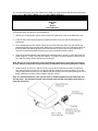
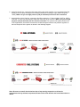
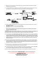
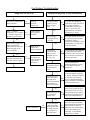
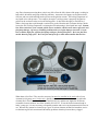
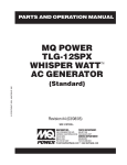
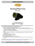
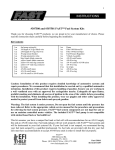
11101, 11108 & 11151 INSTALLATION INSTRUCTIONS
WARNING!
The fuel system is under pressure. Do not open the fuel system until the pressure has
been relieved. Refer to the appropriate vehicle service manual for the procedure and precautions
for relieving the fuel system pressure.
To use this pump in your vehicle’s fuel system, you must do the following:
•
•
•
•
•
•
•
•
A by-pass style fuel pressure regulator must be used in the system.
Utilize AN-10 size high pressure fuel lines, fittings and o-rings for all
connections from the fuel tank pickup to the fuel pump.
To ensure proper fuel pump performance and longevity, mount pump level with
or lower than the bottom, and as close to the tank, as possible.
Install a 12304 pre-filter and 12301 post filter.
If you are using a stock fuel tank, install a reservoir sump in the bottom-rear of
your fuel tank. Exercise extreme caution and follow all manufacturers’
recommendations when installing a reservoir sump. (Sump part # 18650)
Tank/Fuel cell must have at least a ½” tank vent.
If you choose not to install a reservoir sump, then you must install a high flow
capacity fuel tank pickup (9/16” to 5/8” inner tube diameter). Installing pickup
tube instead of a reservoir sump may shorten the fuel pump life and cause
drivability problems. When using a pickup, you should maintain at least ½ tank
of fuel to avoid possible engine lean-out and/or fuel pump damage.
For long term driving applications where continuous run times exceed 30
minutes and fuel capacity is less then 10 gallons, Aeromotive recommends the
installation of a Fuel Pump Speed Controller to maintain lower fuel
temperatures in the tank. See Aeromotive Fuel Pump Speed Controller 16306.
Failure to follow the above may result in fuel leakage, bursting of the fuel lines, poor
vehicle performance and/or decreased fuel pump life! Improper installation will void all
warranties for this product!
CAUTION:
Installation of this product requires detailed knowledge of automotive systems and
repair procedures. We recommend that this installation be carried out by a qualified automotive
technician.
Installation of this product requires handling of gasoline. Ensure you are working in a
well ventilated area with an approved fire extinguisher nearby. Extinguish all open flames,
prohibit smoking and eliminate all sources of ignition in the area of the vehicle before
proceeding with the installation.
The enclosed Aeromotive fuel pump utilizes AN-10 ORB (O-ring Boss Ports) style inlet and outlet ports;
these ports are NOT PIPE THREAD and utilize NO THREAD SEALANT.
Compatible Fuels:
Pump Gas
Race Gas
E85
Diesel
Alcohol/Ethanol
The following steps are typical of most installations:
1. Referring to the appropriate vehicle service manual for instructions, remove the OEM fuel pump.
2. Install an after-market sumped high flow capacity fuel tank or fuel cell, per the manufacturer’s
instructions.
3. Find a suitable place on the vehicle chassis to mount the fuel pump. Make sure the location will
accommodate the pump mounting bolts. Make sure to position the pump at or below the bottom of
the tank. Make sure that the pump is clear of the exhaust, is clear of any moving suspension or
drivetrain components and will keep the pump clear of road obstructions or debris.
4. Using the enclosed template, mark and drill four mounting holes to accept ¼” bolts. Mount the fuel
pump using four ¼” bolts, nuts and lock washers. For quieter fuel pump operation use Aeromotive
p/n 11601 fuel pump vibration dampening mounting kit.
Note: Be sure to route all fuel lines clear of any moving suspension or drive train components,
and any exhaust components! Protect fuel lines from abrasion and road obstructions or debris.
5. Using minimum of 9/16” ID or AN-10 fuel line, connect the fuel tank sump outlet to a 12304 fuel
filter. Using the same size fuel line connect the fuel filter outlet to the fuel pump inlet, or if you are
using an Aeromotive fuel filter you can attached the filter directly to the fuel pump utilizing an AN-10
fitting (15608) and 2 sealing o-rings (10AN o-ring pack 15623).
Note: It is recommended that a fuel shut off valve be installed between the fuel tank outlet and
the fuel pump. Use Aeromotive part # 12331 shutoff valve fuel filter and 15640 swivel fitting to
make the connection.
6. Using AN-10 fuel line, connect the fuel pump outlet to the 12301 fuel filter. You can attached the filter
directly to the fuel pump utilizing an AN-10 fitting (15608) and 2 sealing o-rings (10AN o-ring pack
15623). Make sure you use high pressure (150 psi minimum) fuel line for this connection!
7. Using AN-08 or AN-10 fuel line, connect the fuel filter outlet to the “Y” block (15620, 15675 or 15674).
From the “Y” block use AN-08 lines to make the connection to the fuel rails. Make sure you use high
pressure (150 psi minimum) fuel line for this connection! For optimum fuel system performance
in EFI applications, Aeromotive recommends a balanced system with the fuel pressure regulator as
the last component in the system as shown in the following diagram.
Note: Be sure to route all electrical wires clear of any moving suspension or drivetrain
components and any exhaust components! Protect wires from abrasion and road obstructions or
debris.
8. Make sure you use stranded, insulated copper wire, in the sizes shown, with matching crimp-type
connectors for all connections.
9. Locate the OEM fuel pump supply wires, located near the OEM fuel pump mounting location. Using
that supply wire, connect the Aeromotive fuel pump as shown in the following diagram.
10. Attach a suitable, non-liquid filled fuel pressure gauge to the fuel system schrader valve, fuel rail or
fuel pressure regulator.
P/N 15632 0-15 PSI (1 ½”) “Dry” Fuel Pressure Gauge
P/N 15633 0-100 PSI (1 ½”) “Dry” Fuel Pressure Gauge
Ensure that any spilled fuel and any fuel soaked shop towels are cleaned up and removed
from the vicinity of the vehicle.
CAUTION: While performing the following steps, if any fuel leaks are detected, immediately turn
the ignition to OFF, remove any spilled fuel and repair the leak(s) before proceeding!
11. Turn the ignition to ON without starting the engine, allow the pump to run for several seconds and
check the fuel pressure. If there is no pressure, turn the ignition to OFF, wait one minute, then turn the
ignition to ON and recheck the pressure. Repeat this ignition OFF and ON procedure until the gauge
registers pressure or you detect a fuel leak. If no pressure is registered on the gauge after running the
pump for several seconds and you have found no leaks, check all fuel and electrical connections to
determine the cause.
12. Once the fuel pressure gauge registers pressure, start the engine. The fuel pressure gauge should
register between 40 and 70 psi. If you have installed an adjustable fuel pressure regulator, adjust it to
the desired setting. (For maximum fuel system performance, we recommend using an Aeromotive
adjustable fuel pressure regulator; call us for info.)
13. Shut the engine off. Using suitable clips and other mounting hardware, secure the newly installed fuel
lines and electrical wires by attaching them to the vehicle chassis.
14. Test-drive the vehicle to insure proper operation and re-check the fuel system for leaks. If any leaks
are found, immediately discontinue use of the vehicle and repair the leak(s)!
Aeromotive system components are not legal for sale or use on emission controlled motor vehicles.
Thanks for purchasing another quality product designed, engineered and manufactured in
Kansas City, USA!
AEROMOTIVE, INC.
7805 Barton Street, Lenexa, KS 66214
913-647-7300 fax 913-647-7207
Fuel System Troubleshooting
Pump does not run at all.
Do you have voltage at the
pump terminals?
No
Pump performs poorly or runs intermittently
Check all
electrical
connections.
Is the fuel pressure
regulator you are
using a by-pass
style?
Yes
Is the “+”terminal
connected to +12 V and the
“-“ terminal connected to
the battery ground cable?
No
Yes
Connect power
wires to proper
terminals.
Are you using a
sumped fuel tank or
a fuel cell?
Yes
Is the fuel line going to the
engine compartment
connected to the same side
of the fuel pump as the
power terminals?
No
Yes
Do you have a 100-micron
fuel filter installed on the
inlet side of the fuel pump?
Yes
No
No
No
Yes
Plumb the fuel
pump in the
proper orientation.
Is the fuel line
between the fuel
tank / fuel cell a
minimum of 9/16”
ID or AN-10?
Debris may have
entered the fuel
pump and locked
it up, Contact
Aeromotive.
No
Yes
Is the fuel pump
mounted at or below
the half tank fuel
level?
Contact Aeromotive
No
Yes
Does the fuel filter
on the inlet side of
the pump have a
100-micron filtration
rating and have a
min. of 60 in2 area?
No
Yes
Are the fuel filters in
the system been
clean or new?
No
Yes
Contact Aeromotive
No
Are you driving the
vehicle for periods
of time greater then
30 minute with less
the 10 gallons of
fuel in the tank?
Yes
A by-pass style regulator is
required for proper operation of
this product. For EFI we
recommend Aeromotive p/n
13101 or 13109. For carb
applications we recommend
Aeromotive p/n 13204.
A sumped fuel tank or fuel cell
is required for proper product
performance, refer to
Aeromotive tech bulletin #802
“Pickup tubes -vs- sump feed”
for specific details.
Clean, high flow inlet plumbing
is required for proper pump
operation, a min. of 9/16” ID or
AN-10 fuel line is required on
the pump inlet side.
The fuel pump must be
mounted such that it is gravity
feed to insure a long and
healthy life.
The fuel filter on the inlet side
of the fuel pump is required to
be rated at 100-micron and have
no less then 60 in2 filtering
area, for detailed information
refer to Aeromtive tech bulletin
#101 titled “Inlet Filter”.
Insure that all fuel filters are
clean or new, proper filters are
an inexpensive cure to a lot of
fuel system problems. Refer to
Aeromotive tech bulletin #102
titled “Post Pump Filtration”.
As the fuel level falls in your
tank it is being recirculated at
an increasing rate, allowing less
time for fuel cool down, in
these cases it is recommended
to use a Fuel Pump Speed
Controller, we recommend
Aeromotive p/n 16306.
Aeromotive, Inc. Technical Bulletin #101
From:
Aeromotive Technical Department
Date:
10/10/2011
Re:
Fuel Filtration: Selecting the correct filter to prevent lean-out and pump failure.
STOP!! If you are selling or installing a fuel filter on the inlet of an Aeromotive fuel pump, be
certain you do not use a filter that causes more problems than it solves. For pump inlet
filtration, use only Aeromotive 100-micron P/N #12304, #12302 or an acceptable equivalent
(see specifications below). Do not install the Aeromotive P/N #12301 or 12310 filter with 10micron fabric element on the inlet of any Aeromotive fuel pump, they are however perfect for
use on the outlet of the pump, and this is the only location for which they are recommended.
You may run any brand of filter you choose on your car, just be certain that it meets the following
requirements: The filter element used on the inlet side of any Aeromotive fuel pump may be no
finer than 100-micron (no number smaller than 100), with a surface area of 60 square inches or
more.
Any filter element not meeting these criteria may fail to flow the full volume of the pump, resulting in
both vehicle drivability and pump reliability problems. Aeromotive fuel pumps are engineered to be
efficient, and can create both high outlet pressure and high inlet vacuum. The boiling temperature of
any liquid varies with pressure. For example, the engine’ cooling system is purposely designed to
pressurize the coolant in order to raise the boiling point. So how does this apply to fuel delivery?
When a fuel pump has to pull through a restriction to get fuel from the tank a vacuum develops which
lowers the fuel’s boiling temperature, cavitating the fuel and turning it from liquid into vapor. Bottom
line: Inlet restrictions create vacuum, which causes cavitation, which in turn causes vapor-lock and
fuel pump damage. Of course, drivability problems and even engine damage can result! Lesson:
Don’t combine high flow, efficient fuel pumps with poor flowing inlet filters. Don’t use fuel lines
smaller than the pump ports. Don’t use fuel tank pick-ups or tank outlets smaller than the line.
What about a fine filter? They are also necessary, but must be installed on the outlet side of your
Aeromotive fuel pump, never on the inlet. Options include the Aeromotive 10-micron (replaceable
element) fabric filter assemblies P/N #12301 and P/N #12310, and the new, high-flow 40-micron
(cleanable element) stainless steel filter assembly P/N #12335. Given the alcohol content found in
today’s pump gas, it is now necessary to frequently monitor and service any downstream fuel filters in
use. Because they cannot be cleaned, keep a spare 10-micron element on hand for immediate service
to eliminate engine fuel starvation and drivability problems when they become heavy clogged.
All Aeromotive pumps except the Pro Series EFI pump may use the Aeromotive filter #12304
with –10 inlet and outlet fittings and 100-micron stainless steel element. The Pro Series EFI
pump #11102 requires filter #12302 with larger stainless steel element and –12 inlet and outlet
fittings. The #12302 is also recommended for the #11104 EFI Eliminator pump and our new
#11105 belt drive pump (try 400gph or 2700lb/hr of fuel delivery at 100psi!!). Though Genuine
Aeromotive Filters may be somewhat more expensive than the off-brand options, you simply
must “compare apples to apples”. They say “a picture is worth a thousand words…”
Above are various versions of “100-micron” fuel filters/elements. Note: the top element is the
Aeromotive 100-micron element P/N #12604, as found the fuel filter assembly P/N #12304. Note the
various filters all have “billet” housing, with AN connections, and can be disassembled for inspection
and cleaning. Also, note that all are sold and recommended as appropriate pre-filters.
Of course, it’s obvious by this comparison image that there’s more to a filter than the micron rating, a
billet housing or even AN Connections. It should be equally clear that surface area, the amount of
filter material available for fuel flow, is not at all related to micron rating, but a major key to a filters
flow capacity. All these filters may be fine, well made assemblies, and perhaps they are suitable for
use with various fuel pumps on various engines; However, excepting the very top element which is
there for comparison, none of the above belong in any system featuring an Aeromotive fuel
pump and certainly not any car, boat, truck, etc. that features an engine worthy of such a pump.
AEROMOTIVE, INC. LIMITED WARRANTY
This Aeromotive Product, with proof of purchase dated on or after January 1, 2003, is warranted to be
free from defects in materials and workmanship for a period of one year from the original date of
purchase. No warranty claim will be valid without authentic, dated proof of purchase.
This warranty is to the original retail purchaser and none other and is available directly from
Aeromotive and not through any point of distribution or purchase.
If a defect is suspected, the retail purchaser must contact Aeromotive directly to discuss the problem,
possible solutions and obtain a Return Goods Authorization (RGA), if deemed necessary by the
company. Please call 913-647-7300 and dial option 3 for the technical service dept. All returns must
be shipped freight pre-paid to the company and with valid RGA before they will be processed.
Aeromotive will examine any product returned with the proper authorization to determine if the failure
resulted from a defect or from abuse, improper installation, misapplication or alteration. Aeromotive
will then, at it’s sole discretion, return, repair or replace the product.
If any Aeromotive product is determined defective, buyer’s exclusive remedy is limited in value to the
sale price of the good. In no event shall Aeromotive be liable for incidental or consequential
damages.
Aeromotive expressly retains the right to make changes and improvements in any product it
manufactures and sells at any time. These changes and improvements may be made without notice
at any time and without any obligation to change the catalogs or printed materials.
Aeromotive expressly retains the right to discontinue at any time and without notice any Aeromotive
product that it manufactures or sells.
This warranty is limited and expressly limits any implied warranty to one year from the date of the
original retail purchase on all Aeromotive products.
No person, party or corporate entity other than Aeromotive shall have the right to: determine whether
or not this Limited Warranty is applicable to any Aeromotive product, authorize any action whatsoever
under the terms and conditions of this Limited Warranty, assume any obligation or liability of any
nature whatsoever on behalf of Aeromotive under the terms and conditions of this Limited Warranty.
This Limited Warranty covers only the product itself and not the cost of installation or removal.
This Limited Warranty is in lieu of and expressly excludes any and all other warranties, expressed or
implied. This Limited Warranty gives you specific legal rights, and you may also have other rights
which vary from state to state.
Aeromotive, Inc. 7805 Barton Street, Lenexa, KS 66214 Phone: (913) 647-7300 Fax: (913) 647-7207