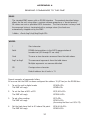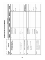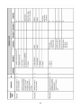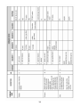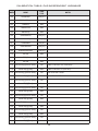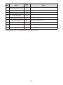
1
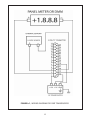
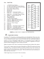
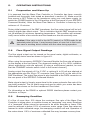
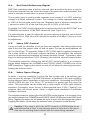
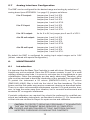
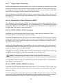
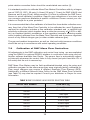
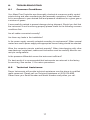
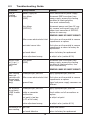
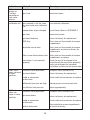
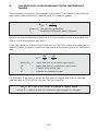
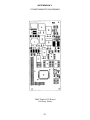
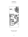
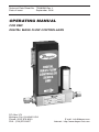
Technical Data Sheet No. TD9805M Rev. L Date of issue: September, 2006 OPERATING MANUAL FOR DMF DIGITAL MASS FLOW CONTROLLERS P.O. Box 373 Michigan City, IN 46361 USA Phone: (219) 879 8000 FAX: (219) 879 9057 E mail: [email protected] Internet: http://www.dwyer-inst.com TABLE OF CONTENTS 1. UNPACKING THE DMF MASS FLOW CONTROLLER........................1 1.1 Inspect Package for External Damage.............................................. 1 1.2 Unpack the Mass Flow Controller....................................................... 1 1.3 Returning Merchandise for Repair.....................................................1 2. INSTALLATION.................................................................... 1 2.1 Primary Gas Connections.................................................................1 2.2 Electrical Connections...................................................................... 2 2.3 Communication Parameters and Connections................................ 2 3. PRINCIPLE OF OPERATION.................................................. 6 4. SPECIFICATIONS.................................................................. 6 4.1 DMF 41 Mass Flow Controllers.........................................................7 4.2 CE Compliance................................................................................ 8 5. OPERATING INSTRUCTIONS..................................................... 11 5.1 Preparation and Warm Up................................................................11 5.2 Flow Signal Output Readings.............................................................. 11 5.3 Swamping Condition........................................................................... 11 5.4 Set Point Reference Signal .............................................................12 5.5 Valve OFF Control .......................................................................... 12 5.6 Valve Open/Purge ............................................................................12 5.7 Analog Interface Configuration........................................................... 13 6. MAINTENANCE...................................................................3 13 6.1 Introduction........................................................................................ 13 6.2 Flow Path Cleaning.............................................................................. 14 6.2.1 Restrictor Flow Element (RFE)................................................. 14 6.2.2 DMF 41401-41411 models.......................................................... 14 6.2.3 DMF 41431-41842 models.......................................................... 14 6.2.4 Valve Maintenance ...................................................................15 7. CALIBRATION PROCEDURES.................................................... 15 7.1 Flow Calibration................................................................................... 15 7.2 Calibration of DMF Mass Flow Controllers.......................................16 17 8. TROUBLESHOOTING............................................................. 17 8.1 Common Conditions........................................................................... 8.2 Technical Assistance............................................................................ 17 8.3 Troubleshooting Guide.................................................................... 18 9. CALIBRATION CONVERSIONS FROM REFERENCE GASES................20 APPENDIX 1 COMPONENT DIAGRAM...................................................... 21 APPENDIX 2 GAS FACTOR TABLE ("K" FACTORS)..................................... 25 APPENDIX 3 DIMENSIONAL DRAWINGS.................................................. 29 APPENDIX 4 31 SENDING COMMANDS TO THE DMF........................................ APPENDIX 5 37 SDPROC TABLES: GAS DEPENDENT VARIABLES.................... 39 GAS INDEPENDENT VARIABLES............... APPENDIX 6 WARRANTY........................................................................... 41 1. UNPACKING THE DMF MASS FLOW CONTROLLER 1.1 Inspect Package for External Damage Your DMF Mass Flow Controller was carefully packed in a sturdy cardboard carton, with anti-static cushioning materials to withstand shipping shock. Upon receipt, inspect the package for possible external damage. In case of external damage to the package contact the shipping company immediately. 1.2 Unpack the Mass Flow Controller Open the carton carefully from the top and inspect for any sign of concealed shipping damage. In addition to contacting the shipping carrier please forward a copy of any damage report to your distributor or Dwyer directly. When unpacking the instrument please make sure that you have all the items indicated on the Packing List. Please report any shortages promptly. 1.3 Returning Merchandise for Repair Please contact the customer service representative of your distributor or Dwyer if you purchased your Mass Flow Controller directly, and request a Return Authorization Number (RAN). Equipment returned without an RAN will not be accepted. Dwyer reserves the right to charge a fee to the customer for equipment returned under warranty claims if the instruments are tested to be free from warrantied defects. Shipping charges are borne by the customer. Meters returned "collect" will not be accepted! It is mandatory that any equipment returned for servicing be purged and neutralized of any dangerous contents including but not limited to toxic, bacterially infectious, corrosive or radioactive substances. No work shall be performed on a returned product unless the customer submits a fully executed, signed SAFETY CERTIFICATE. Please request form from the Service Manager. 2. INSTALLATION 2.1 Primary Gas Connections Please note that the DMF Mass Flow Controller will not operate with liquids. Only clean gases are allowed to be introduced into the instrument. If gases are contaminated they must be filtered to prevent the introduction of impediments into the sensor. Caution: DMF transducers should not be used for monitoring OXYGEN gas unless specifically cleaned and prepared for such application. For more information, contact your distributor or Dwyer. 1 Attitude sensitivity of the Mass Flow Controller is +15F. This means that the gas flow path of the Flow Controller must be horizontal within those stated limits. Should there be need for a different orientation of the meter, re-calibration may be necessary. It is also preferable to install the DMF transducer in a stable environment, free of frequent and sudden temperature changes, high moisture, and drafts. Prior to connecting gas lines inspect all parts of the piping system including ferrules and fittings for dust or other contaminants. Be sure to observe the direction of gas flow as indicated by the arrow on the front of the meter when connecting the gas system to be monitored. Insert tubing into the compression fittings until the ends of the properly sized tubings home flush against the shoulders of the fittings. Compression fittings are to be tightened according to the manufacturer's instructions to one and one quarter turns. Avoid over tightening which will seriously damage the Restrictor Flow Elements (RFE's)! DMF transducers are supplied with standard 1/4 inch (DMF 41401-41433) or 3/8 inch (DMF 41842), or optional 1/8 inch inlet and outlet compression fittings which should not be removed unless the meter is being cleaned or calibrated for a new flow range. Using a Helium Leak Detector or other equivalent method perform a thorough leak test of the entire system. (All DMF's are checked prior to shipment for leakage within stated limits. See specifications in this manual.) 2.2 Electrical Connections DMF transducers require a +15VDC and -15VDC power supply to operate. Additionally, a readout panel meter, digital multimeter, or other equivalent device is required to observe the flow signal in analog mode. A variable analog 0-5VDC reference input is required for DMF models to operate in analog mode. The Dwyer SDPROC accessory Command Modules offer a convenient and compact means to fulfill these needs. DMF is supplied with a 25 pin "D" connector. Pin diagram is presented in figure b-2. 2.3 Communication Parameters and Connections Baud rate: Data bits: 9600 baud 8 Stop bit: Parity: 1 NON RS-232 option: Crossover connection has to be established: Pin 11 (TX) of the “D” connector has to be connected to RX (pin 2 on the DB9 connector). Pin 24 (RX) of the “D” connector has to be connected to TX (pin 3 on the DB9 connector). Pin 20 (Common) of the “D” connector has to be connected to GND (pin 5 on the DB9 connector). 2 RS-485 option: The RS485 converter/adapter has to be configured for: multidrop, 2 wire, half duplex mode. The transmitter circuit has to be enabled by TD or RTS (depending on which is available on the converter/adapter). Settings for the receiver circuit usually should follow the selection made for the transmitter circuit in order to eliminate Echo. Pin 11 (-) of the “D” connector has to be connected to T- or R- on the RS-485 converter/adapter. Pin 24 (+) of the “D” connector has to be connected to T+ or R+ on the RS-485 converter/adapter. Pin 20 (Common) of the “D” connector has to be connected to GND on the RS-485 converter/adapter. 3 FIGURE b-1, WIRING DIAGRAM FOR DMF TRANSDUCERS. 4 PIN FUNCTION 1 2 3 4 5 6 7 8 9 10 11 12 13 14 15 16 17 18 19 20 21 22 23 24 25 +15 VDC Power Supply 0-5 VDC Flow Signal (4-20mA Option) 0-5 VDC Set Point Input (4-20mA Option) Force Valve Open Control Force Valve Closed Control (Reserved) (Reserved) Relay No. 1 - Common Contact Relay No. 1 - Normally Open Contact Relay No. 2 - Normally Closed Contact RS485 (-) (Optional RS232 TX) (No Connection) Chassis Ground -15 VDC Power Supply Common, Signal Ground For Pin 2 Common, Signal Ground For Pin 3 (Optional) RS232 Common Common, Power Supply Common Common Relay No. 1 - Normally Closed Contact Relay No. 2 - Common Contact Relay No. 2 - Normally Open Contact RS485 (+) (Optional RS232 RX) Return for Pin 2 (Optional 4-20 mA Only) FIGURE b-2, DMF 25 PIN "D" CONNECTOR CONFIGURATION Important notes: In general, "D" Connector numbering patterns are standardized. There are, however, some connectors with nonconforming patterns and the numbering sequence on your mating connector may or may not coincide with the numbering sequence shown in our pin configuration table above. It is imperative that you match the appropriate wires in accordance with the correct sequence regardless of the particular numbers displayed on your mating connector. Make sure power is OFF when connecting or disconnecting any cables in the system. The (+) and (-) power inputs are each protected by a 500mA M (medium time-lag) resettable fuse. If a shorting condition or polarity reversal occurs, the fuse will cut power to the flow transducer circuit. Disconnect the power to the unit, remove the faulty condition, and reconnect the power. The fuse will reset once the faulty condition has been removed. Cable length may not exceed 9.5 feet (3 meters). 5 Use of the DMF flow transducer in a manner other than that specified in this manual or in writing from Dwyer, may impair the protection provided by the equipment. 3. PRINCIPLE OF OPERATION The stream of gas entering the Mass Flow transducer is split by shunting a small portion of the flow through a capillary stainless steel sensor tube. The remainder of the gas flows through the primary flow conduit. The geometry of the primary conduit and the sensor tube are designed to ensure laminar flow in each branch. According to principles of fluid dynamics the flow rates of a gas in the two laminar flow conduits are proportional to one another. Therefore, the flow rates measured in the sensor tube are directly proportional to the total flow through the transducer. In order to sense the flow in the sensor tube, heat flux is introduced at two sections of the sensor tube by means of precision wound heater sensor coils. Heat is transferred through the thin wall of the sensor tube to the gas flowing inside. As gas flow takes place heat is carried by the gas stream from the upstream coil to the downstream coil windings. The resultant temperature dependent resistance differential is detected by the electronic control circuit. The measured gradient at the sensor windings is linearly proportional to the instantaneous rate of flow taking place. An output signal is generated that is a function of the amount of heat carried by the gases to indicate mass molecular based flow rates. Additionally, DMF model Mass Flow Controllers incorporate a microprocessor and non-volatile memory that stores all calibration factors and directly controls a proportionating solenoid valve. The digital closed loop control system of the DMF continuously compares the mass flow output with the selected flow rate. Deviations from the set point are corrected by compensating valve adjustments, thus maintaining the desired flow parameters with a high degree of accuracy. 4. SPECIFICATIONS FLOW MEDIUM: Please note that DMF Mass Flow Controllers are designed to work with clean gases only. Never try to meter or control flow rates of liquids with any DMF. CALIBRATIONS: Performed at standard conditions [14.7 psia (1.01 bars) and 70F F (21.1FC)] unless otherwise requested or stated. ENVIRONMENTAL (PER IEC 664): Installation Level II; Pollution Degree II. 6 4.1 DMF Mass Flow Controllers ACCURACY: +1% of full scale, including linearity for gas temperatures ranging from 59FF to 77F F (15F C to 25F C) and pressures of 10 to 60 psia (0.7 to 4.1 bars). REPEATABILITY: +0.15% of full scale. TEMPERATURE COEFFICIENT: 0.1% of full scale/ FC. PRESSURE COEFFICIENT: 0.01% of full scale/psi (0.07 bar). RESPONSE TIME: DMF 41401-41411: 300ms time constant; approximately 1 second to within +2% of set flow rate for 25% to 100% of full scale flow. DMF41431-41842: 600ms time constant; approximately 2 seconds to within +2% of set flow rate for 25% to 100% of full scale flow. GAS PRESSURE: 500 psig (34.5 bars) maximum; optimum pressure is 20 psig (1.4 bars); 25 psig (1.7 bars gauge) for DMF 41842. DIFFERENTIAL PRESSURES REQUIRED: 5 to 50 psig (0.35 to 3.34 bars) differential pressures. Optimum differential pressure is 25 psid (1.7 bars). See Table IV for pressure drops associated with various models and flow rates. MAXIMUM PRESSURE DIFFERENTIAL: 50 psid for DMF 41401-41433, 40 psid for DMF 41842. GAS AND AMBIENT TEMPERATURE: 41F F to 122FF (5F C to 50F C). RELATIVE GAS HUMIDITY: Up to 70%. LEAK INTEGRITY: 1 x 10⁻⁹ sccs He maximum to the outside environment. ATTITUDE SENSITIVITY: 1% shift for a 90 degree rotation from horizontal to vertical; standard calibration is in horizontal position. OUTPUT SIGNALS: Linear 0-5 VDC (2000 : minimum load impedance); 4-20 mA optional (50-500 :loop resistance); 20 mV peak to peak max noise. Contact your distributor or Dwyer for optional RS232 or IEEE488 interfaces. COMMAND SIGNAL: 0-5 VDC (200K :input impedance); 4-20 mA optional. TRANSDUCER INPUT POWER: DMF - +15 +5% VDC, 450 mA max, 6.75 watts max; -15 +5% VDC, 450 mA max; 6.75 watts max; Power inputs are each protected by a 500mA M (medium time-lag) resettable fuse, and an inverse shunt rectifier diode for polarity protection. WETTED MATERIALS: 316 stainless steel, 416 stainless steel, VITON7 O-rings; BUNA-N7, NEOPRENE7 or KALREZ7 O-rings are optional. 7 Dwyer makes no expressed or implied guarantees of corrosion resistance of mass flow meters as pertains to different flow media reacting with components of meters. It is the customers' sole responsibility to select the model suitable for a particular gas based on the fluid contacting (wetted) materials offered in the different models. INLET AND OUTLET CONNECTIONS: 1/4" (DMF 41401-41433) (DMF 41842) or 3/8" compression fittings standard; 1/8" or 3/8" compression fittings and 1/4" VCR7 fittings are optional. TRANSDUCER INTERFACE CABLE: Flat cable with 25-pin "D" connectors on the ends is standard. Optional shielded cable is available with male/female 25-pin "D" connector ends. [Cable length may not exceed 9.5 feet (3 meters)] 4.2 CE Compliance Any model DMF bearing a CE marking on it, is in compliance with the below stated test standards currently accepted. EMC Compliance with 89/336/EEC as amended; Emission Standard: EN 55011:1991, Group 1, Class A Immunity Standard: EN 55082-1:1992 8 FLOW RANGES TABLE I DMF 41 LOW FLOW MASS FLOW CONTROLLERS* CODE scc/min [N2] CODE std liters/min [N2] 401 0 to 10 07 0 to 1 402 0 to 20 08 0 to 2 403 0 to 50 09 0 to 5 404 0 to 100 10 0 to 10 405 0 to 200 406 0 to 500 TABLE II DMF 36 MEDIUM FLOW MASS FLOW CONTROLLERS* CODE standard liters/min [N2] 11 0 to 15 30 20 31 30 32 40 33 50 TABLE III DMF 46 HIGH FLOW MASS FLOW CONTROLLERS* CODE standard liters/min [N2] 40 60 41 80 42 100 * Flow rates are stated for Nitrogen at STP conditions [i.e. 70FF (21.1FC) at 1 atm]. For other gases use the K factor as a multiplier from APPENDIX 2. 9 TABLE IV PRESSURE DROPS MODEL FLOW RATE [std liters/min] MAXIMUM PRESSURE DROP [mm H2O] [psid] [mbar] up to 10 720 1.06 75 15 2630 3.87 266 30 2380 3.50 241 DMF 41433 50 5440 8.00 551 DMF 41842 100 12850 18.89 1302 DMF 41411 DMF 41431 TABLE V APPROXIMATE WEIGHTS MODEL WEIGHT SHIPPING WEIGHT DMF 41401-41411 controller 2.20 lbs (1.00 kg) 3.70 lbs (1.68 kg) DMF 41431-41842 controller 2.84 lbs (1.29 kg) 4.34 lbs (1.97 kg) 10 5. OPERATING INSTRUCTIONS 5.1 Preparation and Warm Up It is assumed that the Mass Flow Controller or Controller has been correctly installed and thoroughly leak tested as described in section (2). Make sure the flow source is OFF. Power up the transducer using your own power supply (or switch the POWER switch to the ON position at the front panel of your SDPROC Command Module). Allow the Mass Flow Meter or Controller to warm-up for a minimum of 15 minutes. During initial powering of the DMF transducer, the flow output signal will be indicating a higher than usual output. This is indication that the DMF transducer has not yet attained it's minimum operating temperature. This condition will automatically cancel within a few minutes and the transducer should eventually zero. 5.2 Caution: If the valve is left in the AUTO (control) or OPEN mode for an extended period of time, it may become warm or even hot to the touch. Use care in avoiding direct contact with the valve during operation. Flow Signal Output Readings The flow signal output can be viewed on the panel meter, digital multimeter, or other display device used as shown in figure b-1. When using the accessory SDPROC Command Module the flow rate will appear on the display at the front panel. The observed reading is a 0 to 100% indication (direct engineering units are optional). [If using a multichannel readout, be sure that the CHANNEL selector switch is set to the correct channel.] Analog output flow signals of 0 to 5 VDC or optional 4 to 20 mA are attained at the appropriate pins the 25-pin "D" connector (see Figure b-2) on the side of the DMF transducer. The output flow signal is also available at the DATA connector on the rear panel of the SDPROC Command Module. Meter signal output is linearly proportional to the mass molecular flow rate of the gas being metered. The full scale range and gas for which your meter has been calibrated are shown on the flow transducer's front label. For information on the RS485 or optional RS232 interfaces please contact your distributor or Dwyer. 5.3 Swamping Condition If a flow of more than 10% above the maximum flow rate of the Mass Flow Controller is taking place, a condition known as "swamping" may occur. Readings of a "swamped" meter cannot be assumed to be either accurate or linear. Flow must be restored to below 110% of maximum meter range. Once flow rates are lowered to within calibrated range, the swamping condition will end. Operation of the meter above 110% of maximum calibrated flow may increase recovery time. 11 5.4 Set Point Reference Signal DMF flow controllers have a built-in solenoid valve and allow the user to set the flow to any desired flow rate within the range of the particular model installed. This valve is normally closed when no power is applied. The set point input in analog mode responds to an analog 0 to 5 VDC reference voltage or 4-20mA reference current. This voltage is a linear representation of 0 to 100% of the full scale mass flow rate. Response time to set point changes are 1 second to within 2% of the final flow over 25 to 100% of full scale. A variable 0 to 5VDC analog signal may be applied directly to the SET POINT and COMMON connections of the DMF transducer (see Figure b-1). If a potentiometer is used to adjust the set point reference signal its value should be between 5K to 100K ohm and it should be capable of at least 10-turns or more for adjustment. 5.5 Valve OFF Control It may, at times, be desirable to set the flow and maintain that setting while being able to turn the flow control valve off and on again. This can be accomplished via pin 5 on the 25-pin "D" connector. When 0 VDC (LOW) signal is applied (connection via a relay, switch or NPN open collector transistor is permissible), the solenoid valve is not powered and therefore will remain normally closed. Conversely, when the pin is disconnected from 0 VDC ("floating”) the solenoid valve will remain active. The simplest means for utilizing the VALVE OFF control feature, is to connect a toggle switch between the COMMON and FORCE VALVE CLOSED pins of the DMF transducer. Toggling the switch on and off will allow for activating and deactivating the solenoid valve. 5.6 Valve Open /Purge At times, it may be necessary to purge the flow system with a neutralizing gas such as pure dry nitrogen. The DMF transducer is capable of a full open condition for the solenoid valve, regardless of set point conditions. Connecting the FORCE VALVE OPEN pin (pin 4 on 25-pin "D" connector) to ground will fully open the valve. This connection can be made with a relay, switch or NPN open collector transistor. Conversely, when the pin is disconnected from 0 VDC ("floating”) the solenoid valve will remain active. (Note: in digital mode hardware I/O overrides software command) The simplest means for utilizing the VALVE OPEN control feature, is to connect a toggle switch between the COMMON and FORCE VALVE OPEN pins of the DMF transducer. Toggling the switch on will cause the valve to open fully and purge the system. Toggling the switch off will allow the solenoid valve to resume normal activity. Caution: If the valve is left in the AUTO (control) or OPEN mode for an extended period of time, it may become warm or even hot to the touch. Use care in avoiding direct contact with the valve during operation. 12 5.7 Analog Interface Configuration The DMF can be configured for the desired range and scaling by selection of analog board (see APPENDIX 1 on page 21) jumpers as follows: 0 to 5 V output: Jumper Jumper Jumper Jumper pins pins pins pins 0 to 5 V input: Jumper pins 2 and 3 of JP2. Jumper pins 2 and 3 of JP4. Jumper pins 1 and 2 of JP11. 0 to 10 V output: As for 0 to 5V, but jumper pins 2 and 3 of JP12. 4 to 20 mA output: Jumper Jumper Jumper Jumper 4 to 20 mA input: Jumper pins 1 and 2 of JP2. Jumper pins 1 and 2 of JP4. Jumper pins 1 and 2 of JP11. pins pins pins pins 2 2 2 1 1 1 1 1 and and and and and and and and 3 3 3 2 2 2 2 2 of of of of of of of of JP6. JP3. JP5. JP12. JP6. JP3. JP5. JP12. By default the DMF is configured for analog input output ranges set to 0-5V (unless ordered with special configuration). 6. MAINTENANCE 6.1 Introduction It is important that the Mass Flow Controller is used with clean, filtered gases only. Liquids may not be metered. Since the RTD sensor consists, in part, of a small capillary stainless steel tube, it is prone to occlusion due to impediments or gas crystallization. Other flow passages are also easily obstructed. Therefore, great care must be exercised to avoid the introduction of any potential flow impediment. To protect the instrument a 50 micron (DMF41401-41411) or 60 micron (DMF41431-41842) filter is built into the inlet of the flow transducer. The filter screen and the flow paths may require occasional cleaning as described below. There is no other recommended maintenance required. It is good practice, however, to keep the meter away from vibration, hot or corrosive environments and excessive RF or magnetic interference. If periodic calibrations are required they should be performed by qualified personnel and calibrating instruments, as described in section (7). It is recommended that units are returned to Dwyer for repair service and calibration. CAUTION: TO PROTECT SERVICING PERSONNEL IT IS MANDATORY THAT ANY INSTRUMENT BEING SERVICED IS COMPLETELY PURGED AND NEUTRALIZED OF TOXIC, BACTERIOLOGICALLY INFECTED, CORROSIVE OR RADIOACTIVE CONTENTS. 13 6.2 Flow Path Cleaning Before attempting any disassembly of the unit for cleaning, try inspecting the flow paths by looking into the inlet and outlet ends of the meter for any debris that may be clogging the flow through the meter. Remove debris as necessary. If the flow path is not unclogged, then proceed with steps below. Do not attempt to disassemble the sensor. If blockage of the sensor tube is not alleviated by flushing through with cleaning fluids, please return meter to Dwyer for servicing. 6.2.1 Restrictor Flow Element (RFE) The Restrictor Flow Element (RFE) is a precision flow divider inside the transducer, which splits the inlet gas flow by a preset amount to the sensor and main flow paths. The particular RFE used in a given Mass Flow Controller depends on the gas and flow range of the instrument. 6.2.2 DMF 41401-41411 models Unscrew the inlet compression fitting of meter. Note that the Restrictor Flow Element (RFE) is connected to the inlet fitting. Carefully disassemble the RFE from the inlet connection. The 50 micron filter screen will now become visible. Push the screen out through the inlet fitting. Clean or replace each of the removed parts as necessary. If alcohol is used for cleaning, allow time for drying. Inspect the flow path inside the transducer for any visible signs of contaminants. If necessary, flush the flow path through with alcohol. Thoroughly dry the flow paths by flowing clean dry gas through. Carefully re-install the RFE and inlet fitting, avoiding any twisting and deforming the RFE. Be sure that no dust has collected on the O-ring seal. Note: Overtightening will deform and render the RFE defective. It is advisable that at least one calibration point be checked after re installing the inlet fitting - see section (7). 6.2.3 DMF 41431-41842 models Unscrew the four socket head cap screws (two 10-24 and two 6-32) at the inlet side of the meter. This will release the short square block containing the inlet compression fitting. The 60 micron filter screen will now become visible. Remove the screen. DO NOT remove the RFE inside the flow transducer! Clean or replace each of the removed parts as necessary. If alcohol is used for cleaning, allow time for drying. 14 Inspect the flow path inside the transducer for any visible signs of contaminants. If necessary, flush the flow path through with alcohol. Thoroughly dry the flow paths by flowing clean dry gas through. Re-install the inlet parts and filter screen. Be sure that no dust has collected on the O-ring seal. It is advisable that at least one calibration point be checked after re installing the inlet fitting - see section (7). 6.2.4 Valve Maintenance (DMF) The solenoid valve consists of 316 and 416 stainless steel, and VITON7 (or optional NEOPRENE7 or KALREZ7) O-rings and seals. No regular maintenance is required except for periodic cleaning. Various corrosive gases may demand more frequent replacement of VITON7 O- rings and seals inside the valve. Be sure to use an elastomer material, appropriate for your specific gas application. Contact your distributor or Dwyer for optional sealing materials available. Set the DMF into PURGE mode, and attempt to flush through with a clean, filtered, and neutral gas such as nitrogen. [Another option for fully opening the valve is to remove the plastic cap on top of the valve, and turn the set screw counterclockwise until it stops. Set valve for the closed position. Apply an inlet pressure of 5 psig and atmospheric pressure at the outlet. If a small flow occurs, turn the set screw on top of the solenoid valve clockwise until the flow through the DMF just stops. Note: Removal of the factory installed calibration seals and/or any adjustments made to the meter, as described in this section, will void any calibration warranty applicable. 7. CALIBRATION PROCEDURES 7.1 Flow Calibration Dwyer Instruments' Flow Calibration Laboratory offers professional calibration support for Mass Flow Meters and Controllers, using precision calibrators under strictly controlled conditions. NIST traceable calibrations are available. Calibrations can also be performed at customers' site using available standards. Factory calibrations are performed using NIST traceable precision volumetric calibrators incorporating liquid sealed frictionless actuators. Generally, calibrations are performed using dry nitrogen gas. The calibration can then be corrected to the appropriate gas desired based on relative correction [K] factors shown in the gas factor table see Appendix 2. A reference gas, other than nitrogen, may be used to closer approximate the flow characteristics of certain gases. This practice is recommended when a reference gas is found with thermodynamic properties similar to the actual gas under consideration. The appro- 15 priate relative correction factor should be recalculated see section (9). It is standard practice to calibrate Mass Flow Meters/Controllers with dry nitrogen gas at 70FF (21.1EC), 20 psig (1.4 bars) [25 psig (1.7 bars) for DMF 41842] inlet pressure and 0 psig (0 bar) outlet pressure. It is best to calibrate the DMF transducers to actual operating conditions. Specific gas calibrations of non-toxic and non-corrosive gases are available at specific conditions. Please contact your distributor or Dwyer for a price quotation. It is recommended that a flow calibrator of at least four times better collective accuracy than that of the Mass Flow Controller to be calibrated be used. Equipment required for calibration includes a flow calibration standard and a certified high sensitivity multimeter (which together have a collective accuracy of +0.25% or better), an insulated (plastic) screwdriver, a flow regulator (example: metering needle valve) installed upstream from the Mass Flow Controller and a pressure regulated source of dry filtered nitrogen gas (or other suitable reference gas). The gas and ambient temperature, as well as inlet and outlet pressure conditions should be set up in accordance with actual operating conditions. 7.2 Calibration of DMF Mass Flow Controllers All adjustments to the DMF calibration and control loop tuning are accomplished using the RS485 (or optional RS232) interface in conjunction with setup and calibration software available from Dwyer. The sensor zero is automatically adjusted internally whenever the control valve is fully closed (set point less than 2% of full scale) and the unit is warmed up. DMF Mass Flow Meters may be field recalibrated/checked using the setup and calibration program for the same range they were originally factory calibrated for. Flow range changes may require a different Restrictor Flow Element (RFE). Additionally, a different Solenoid Valve Orifice for the DMF Mass Flow Controller (see Table VI) may also be required. Consult your distributor or Dwyer for more information. TABLE VI DMF SOLENOID VALVE ORIFICE SELECTION TABLE ORIFICE PART NUMBER FLOW RATE [N2] OR.010 Under 10 sccm OR.020 10 to 1000 sccm OR.040 1 to 5 slpm OR.055 5 to 10 slpm OR.063 10 to 15 slpm OR.073 15 to 20 slpm OR.094 20 to 50 slpm OR.125 50 to 100 slpm 16 8. TROUBLESHOOTING 8.1 Common Conditions Your Mass Flow Controller was thoroughly checked at numerous quality control points during and after manufacturing and assembly operations. It was calibrated in accordance to your desired flow and pressure conditions for a given gas or a mixture of gases. It was carefully packed to prevent damage during shipment. Should you feel that the instrument is not functioning properly please check for the following common conditions first: Are all cables connected correctly? Are there any leaks in the installation? Is the power supply correctly selected according to requirements? When several meters are used a power supply with appropriate current rating should be selected. Were the connector pinouts matched properly? When interchanging with other manufacturers' equipment, cables and connectors must be carefully wired for correct pin configurations. Is the pressure differential across the instrument sufficient? For best results it is recommended that instruments are returned to the factory for servicing. See section 1.3 for return procedures. 8.2 Technical Assistance Dwyer Instruments will provide technical assistance over the phone to qualified repair personnel. Please call our Technical Assistance at (219) 879-8000. Please have your Serial Number and Model Number ready when you call. 17 8.3 Troubleshooting Guide Indication Likely Reason Remedy lack of reading or output power supply off check connection of power supply fuse blown (DMF) disconnect DMF transducer from power supply; remove the shorting condition or check polarities; fuse resets automatically fuse blown (SDPROC) disconnect power cord from AC supply; remove and inspect fuses at AC power input connector of SDPROC; replace as necessary REMOVE CAUSE OF SHORT CIRCUIT! filter screen obstructed at inlet flush clean or disassemble to remove impediments or replace output reads at (+) or (-) saturation only occluded sensor tube flush clean or disassemble to remove impediments or return to factory for replacement pc board defect return to factory for replacement valve adjustment wrong re-adjust valve (section 6.2.4) fuse blown (DMF) disconnect DMF transducer from power supply; remove the shorting condition or check polarities; fuse resets automatically REMOVE CAUSE OF SHORT CIRCUIT! flow reading does not coincide with the set point (DMF models only) inadequate gas pressure ground loop signal and power supply commons are different no response to set point (DMF models only) inadequate gas pressure apply appropriate gas pressure cable or connector malfunction check cables and all connections or replace set point is too low (<2% of full scale) re-adjust set point valve adjustment wrong re-adjust valve (section 6.2.4) gas leak locate and correct pc board defective return to factory for replacement unstable or no zero reading apply appropriate gas pressure filter screen obstructed at inlet flush clean or disassemble to remove impediments or replace 18 Indication Likely Reason Remedy full scale output at "no flow" condition or with valve closed defective sensor return to factory for replacement gas Leak locate and repair calibration off gas metered is not the same as what meter was calibrated for use matched calibration composition of gas changed see K factor tables in APPENDIX 2 gas leak locate and correct pc board defective return to factory for replacement RFE dirty flush clean or disassemble to remove impediments occluded sensor tube flush clean or disassemble to remove impediments or return to factory for replacement filter screen obstructed at inlet flush clean or disassemble to remove impediments or replace transducer is not mounted properly check for any tilt or change in the mounting of the transducer; generally, units are calibrated for horizontal installation (relative to the sensor tube) incorrect valve adjustment re-adjust valve (section 6.2.4) pc board defect return to factory for replacement cable or connectors malfunction check cable and connectors or replace differential pressure too high decrease pressure to correct level insufficient inlet pressure adjust appropriately incorrect valve adjustment re-adjust valve (section 6.2.4) pc board defect return to factory for replacement cable or connectors malfunction check cable and connectors or replace orifice obstructed disassemble to remove impediments or return to factory DMF valve does not work in open position DMF valve does not work in close position 19 9. CALIBRATION CONVERSIONS FROM REFERENCE GASES The calibration conversion incorporates the K factor. The K factor is derived from gas density and coefficient of specific heat. For diatomic gases: 1 d X Cp where d = gas density (gram/liter) Cp = coefficient of specific heat (cal/gram) K gas = Note in the above relationship that d and Cp are usually chosen at standard conditions of one atmosphere and 25F C. If the flow range of a Mass Flow Controller or Controller remains unchanged, a relative K factor is used to relate the calibration of the actual gas to the reference gas. K = where Qa Qr Ka Kr = = = = Qa Qr = Ka Kr mass flow rate of an actual gas (sccm) mass flow rate of a reference gas (sccm) K factor of an actual gas K factor of a reference gas For example, if we want to know the flow rate of oxygen and wish to calibrate with nitrogen at 1000 SCCM, the flow rate of oxygen is: QO = Qa = Qr x K = 1000 X 0.9926 = 992.6 sccm 2 where K = relative K factor to reference gas (oxygen to nitrogen) 20 APPENDIX 1 COMPONENTS DIAGRAMS DMF Digital PC Board (Primary Side) 21 APPENDIX 1 (CONTINUED) DMF Digital PC Board (Secondary Side) 22 APPENDIX 1 (CONTINUED) DMF Analog PC Board (Primary Side) 23 APPENDIX 1 (CONTINUED) DMF Analog PC Board (Secondary Side) 24 APPENDIX 2 GAS FACTOR TABLES (“K” FACTORS) Actual Gas K Factor Relative to N2 Cp [Cal/g] Density [g/I] AcetyleneC2H2 Air Allene (Propadiene) C3H4 Ammonia NH3 Argon Ar Arsine AsH3 Boron Trichloride BCl3 Boron Trifluoride BF3 Bromine Br2 Boron Tribromide Br3 Bromine Pentafluoride BrF5 Bromine Trifluoride BrF3 Bromotrifluoromethane (Freon-13 B1) CBrF3 1,3-Butadiene C4H6 Butane C4H10 1-Butane C4H8 2-Butane C4H8 CIS 2-Butane C4H8 TRANS Carbon Dioxide CO2 Carbon Disulfide CS2 Carbon Monoxide C0 Carbon Tetrachloride CCl4 Carbon Tetrafluoride (Freon-14)CF4 Carbonyl Fluoride COF2 Carbonyl Sulfide COS Chlorine Cl2 Chlorine Trifluoride ClF3 Chlorodifluoromethane (Freon-22)CHClF2 Chloroform CHCl3 Chloropentafluoroethane(Freon-115)C2ClF5 Chlorotrifluromethane (Freon-13) CClF3 CyanogenC2N2 CyanogenChloride CICN Cyclopropane C3H5 Deuterium D2 Diborane B2H6 .5829 1.0000 .4346 .7310 1.4573 .6735 .4089 .5082 .8083 .38 .26 .3855 .3697 .3224 .2631 .2994 .324 .291 .7382 .6026 1.00 .31 .42 .5428 .6606 .86 .4016 .4589 .3912 .2418 .3834 .61 .6130 .4584 1.00 .4357 .4036 .240 .352 .492 .1244 .1167 .1279 .1778 .0539 .0647 .1369 .1161 .1113 .3514 .4007 .3648 .336 .374 .2016 .1428 .2488 .1655 .1654 .1710 .1651 .114 .1650 .1544 .1309 .164 .153 .2613 .1739 .3177 1.722 .508 1.162 1.293 1.787 .760 1.782 3.478 5.227 3.025 7.130 11.18 7.803 6.108 6.644 2.413 2.593 2.503 2.503 2.503 1.964 3.397 1.250 6.860 3.926 2.945 2.680 3.163 4.125 3.858 5.326 6.892 4.660 2.322 2.742 1.877 1.799 1.235 25 Actual Gas K Factor Relative to N2 .1947 .3538 .4252 .2522 .4044 .2235 .4271 .3714 .3896 .2170 .50 .3918 .3225 .3891 .60 .5191 .9784 .4967 .3287 .3538 .3834 .3697 .4210 .4252 .4589 .2031 .2240 .2418 .1760 .5696 .2668 1.454 .2421 .1792 1.0106 1.000 1.000 1.070 Dibromodifluoromethane CBr2F2 Dichlorodifluoromethane (Freon-12) CCl2F2 Dichlofluoromethane (Freon-21) CHCl2F Dichloromethylsilane (CH3)2SiCl2 Dichlorosilane SiH2Cl2 Dichlorotetrafluoroethane (Freon-114) C2Cl2F4 1,1-Difluoroethylene (Freon-1132A) C2H2F2 Dimethylamine (CH3)2NH Dimethyl Ether (CH3)2O 2,2-Dimethylpropane C3H12 Ethane C2H6 Ethanol C2H6O Ethyl Acetylene C4H6 Ethyl Chloride C2H5Cl Ethylene C2H4 Ethylene Oxide C2H4O Fluorine F2 Fluoroform (Freon-23) CHF3 Freon-11 CCl3F Freon-12 CCl2F2 Freon-13 CClF3 Freon-13B1 CBrF3 Freon-14 CF4 Freon-21 CHCl2F Freon-22 CHClF2 Freon-113 CCl2FCClF2 Freon-114 C2Cl2F4 Freon-115 C2ClF5 Freon-C318 C4F8 Germane GeH4 Germanium Tetrachloride GeCl4 Helium He Hexafluoroethane C2F6 (Freon-116) Hexane C6H14 Hydrogen H2 Hydrogen Bromide HBr Hydrogen Chloride HCl Hydrogen Cyanide HCN 26 Cp [Cal/g] .15 .1432 .140 .1882 .150 .1604 .224 .366 .3414 .3914 .420 .3395 .3513 .244 .365 .268 .1873 .176 .1357 .1432 .153 .1113 .1654 .140 .1544 .161 .160 .164 .185 .1404 .1071 1.241 .1834 .3968 3.419 .0861 .1912 .3171 Density [g/I] 9.362 5.395 4.592 5.758 4.506 7.626 2.857 2.011 2.055 3.219 1.342 2.055 2.413 2.879 1.251 1.965 1.695 3.127 6.129 5.395 4.660 6.644 3.926 4.592 3.858 8.360 7.626 6.892 8.397 3.418 9.565 .1786 6.157 3.845 .0899 3.610 1.627 1.206 Actual Gas K Factor Relative to N2 Hydrogen Fluoride HF Hydrogen Iodide HI Hydrogen Selenide H2Se Hydrogen Sulfide H2S Iodine Pentafluoride IF5 Isobutane CH(CH3)3 Isobutylene C4H6 Krypton Kr Methane CH4 Methanol CH3 Methyl Acetylene C3H4 Methyl Bromide CH2Br Methyl Chloride CH3Cl Methyl Fluoride CH3F Methyl Mercaptan CH3SH Methyl Trichlorosilane (CH3)SiCl3 Molybdenum Hexafluoride MoF6 Monoethylamine C2H5NH2 Monomethylamine CH3NH2 Neon NE Nitric Oxide NO Nitrogen N2 Nitrogen Dioxide NO2 Nitrogen Trifluoride NF3 Nitrosyl Chloride NOCl Nitrous Oxide N2O Octafluorocyclobutane (Freon-C318) C4F8 Oxygen O2 Oxygen Difluoride OF2 Ozone Pentaborane B5H9 Pentane C5H12 Perchloryl Fluoride ClO3F Perfluoropropane C3F8 Phosgene COCl2 Phosphine PH3 Phosphorous Oxychloride POCl3 Phosphorous Pentafluoride PH5 .9998 .9987 .7893 .80 .2492 .27 .2951 1.453 .7175 .5843 .4313 .5835 .6299 .68 .5180 .2499 .2126 .3512 .51 1.46 .990 1.000 .737 .4802 .6134 .7128 .176 .9926 .6337 .446 .2554 .2134 .3950 .174 .4438 1.070 .36 .3021 27 Cp [Cal/g] Density [g/I] .3479 .0545 .1025 .2397 .1108 .3872 .3701 .0593 .5328 .3274 .3547 .1106 .1926 .3221 .2459 .164 .1373 .387 .4343 .246 .2328 .2485 .1933 .1797 .1632 .2088 .185 .2193 .1917 .195 .38 .398 .1514 .197 .1394 .2374 .1324 .1610 .893 5.707 3.613 1.520 9.90 3.593 2.503 3.739 .715 1.429 1.787 4.236 2.253 1.518 2.146 6.669 9.366 2.011 1.386 .900 1.339 1.25 2.052 3.168 2.920 1.964 8.397 1.427 2.406 2.144 2.816 3.219 4.571 8.388 4.418 1.517 6.843 5.620 Actual Gas K Factor Relative to N2 Cp [Cal/g] Density [g/I] .30 .35 .40 .5982 .284 .3482 .69 .2635 .3883 .5096 .3237 .3287 .3278 .1250 .399 .366 .3189 .1270 .1691 .1488 .1592 .1543 .127 .182 .1357 .1380 6.127 1.967 1.877 1.433 7.580 4.643 2.858 6.516 4.562 4.224 4.64 6.129 6.043 .2031 .161 8.36 .0608 .2691 .32 .2792 .2541 .1961 .4616 .48 1.44 .508 .120 .163 .3710 .0810 .0888 .1241 .12054 .0378 8.848 8.465 5.95 2.639 13.28 15.70 4.772 2.788 5.858 Phosphorous Trichloride PCl3 Propane C3H8 Propylene C3H6 Silane SiH4 Silicon Tetrachloride SiCl4 Silicon Tetrafluoride SiF4 Sulfur Dioxide SO2 Sulfur Hexafluoride SF6 Sulfuryl Fluoride SO2F2 Tetrafluoroethane (Forane 134A) CF3CH2F Tetrafluorohydrazine N2F4 Trichlorofluoromethane (Freon-11) CCl3F Trichlorosilane SiHCl3 1,1,2-Trichloro-1,2,2 Trifluoroethane (Freon-113) CCl2FCClF2 Triisobutyl Aluminum (C4H9)AL Titanium Tetrachloride TiCl4 Trichloro Ethylene C2HCl3 Trimethylamine (CH3)3N Tungsten Hexafluoride WF6 Uranium Hexafluoride UF6 Vinyl Bromide CH2CHBr Vinyl Chloride CH2CHCl Xenon Xe 28 APPENDIX 3 DIMENSIONAL DRAWINGS DMF 41401-41411 Mass Flow Controller NOTES: Dwyer reserves the right to change designs and dimensions at its sole discretion at any time without notice. For certified dimensions please contact Dwyer. 29 DMF 41431-41842 Mass Flow Controller NOTES: Dwyer reserves the right to change designs and dimensions at its sole discretion at any time without notice. For certified dimensions please contact Dwyer. 30 APPENDIX 4 SENDING COMMANDS TO THE DMF RS485 The standard DMF comes with an RS485 interface. The protocol described below allows for the unit using either a custom software program or a “dumb terminal”. All values are sent as printable ASCII characters. The start character is always !and the command string is terminated with a carriage return (line feeds are automatically stripped out by the DMF: !<Addr>, <Cmd>,Arg1,Arg2,Arg3,Arg4<CR> WHERE: ! Start character Addr RS485 device address in the ASCII representation of hexadecimal (00 through FF are valid).** Cmd The one or two character command from the table above. Arg1 to Arg4 The command arguments from the table above. Multiple arguments are comma delimited. CR Carriage return character. ** Default address for all units is 11. Several examples of commands follow. All assume that the DMF has been configured for address 15 (0F hex) on the RS485 bus: 1. To put the unit in digital mode: The DMF will reply: !0F,M,D<CR> !0FMD<CR> 2. To set the flow of 50% of FS: The DMF will reply: !0F,S,50.0<CR> !0FS50.0<CR> 3. To get a flow reading: The DMF will reply: !0F,F<CR> !0F50.0<CR> (Assuming the flow is at 50% FS) 4. Set the high alarm limit to 5% above Set point: The DMF will reply: !0F,A,H,5.0<CR> !0FA5.0<CR> 31 32 33 34 35 36 APPENDIX 5 CALIBRATION TABLE: GAS DEPENDENT VARIABLES DATA TYPE INDEX NAME 0 BlankSDPROC char[10] Do not modify. For internal use only. 1 SerialNumber char[20] 2 ModelNumber char[20] 3 SoftwareVer char[10] 4 TimeSinceCalHr float Time since last calibration in hours. 5 Options uint Misc. Options. 6 AOutOffset_mA int 7 AddressRS485 8 AInScaleV float 9 AInOffsetV float 10 AInScale_mA float 11 AInOffset_mA float 12 AoutScaleV float 13 AoutScale_mA float 14 SensorZero uint 15 Klag[0] float 16 Klag[1] float 17 Klag[2] float 18 Klag[3] float 19 Klag[4] float 20 Klag[5] float 21 Reserved float 22 Reserved float 23 Reserved float 24 Reserved float 25 Reserved float 26 Reserved float 27 Kgain[0] float 28 Kgain[1] float NOTES char[3] Two character address for RS485 only. 37 INDEX NAME DATA TYPE 29 Kgain[2] float 30 Kgain[3] float 31 Kgain[4] float 32 Kgain[5] float 33 Reserved float 34 Reserved float 35 Reserved float 36 Reserved float 37 Reserved float 38 Reserved float 39 ValveTbl[0][open] float Index 0: Valve actuation. Must be 0.0.- Do Not Alter 40 ValveTbl[0][valve value] uint Index 0: Valve: D/A value - Do Not Alter 41 ValveTbl[1][flow] float Index 1: Actual valve opening in % FS. Do Not Alter 42 ValveTbl[1][valve value] uint Index 1: Valve D/A counts corresponding to flow. Do Not Alter 43 ValveTbl[2][flow] float Do Not Alter 44 ValveTbl[2][valve value] uint Do Not Alter 45 ValveTbl[3][flow] float Do Not Alter 46 ValveTbl[3][valve value] uint Do Not Alter 47 ValveTbl[4][flow] float Do Not Alter 48 ValveTbl[4][valve value] uint Do Not Alter 49 ValveTbl[5][flow] float Do Not Alter 50 ValveTbl[5][valve value] uint Do Not Alter 51 ValveTbl[6][flow] float Do Not Alter 52 ValveTbl[6][valve value] uint Do Not Alter 53 ValveTbl[7][flow] float Do Not Alter 54 ValveTbl[7][valve value] uint Do Not Alter 55 ValveTbl[8][flow] float Do Not Alter 56 ValveTbl[8][valve value] uint Do Not Alter 57 ValveTbl[9][flow] float Index 9: Valve fully open. Must be 1.0- Do Not Alter 58 ValveTbl[9][valve value] uint Index 9: D/A count for a fully open valve. Must be 4095.- Do Not Alter 59 AutoTune Time Constant uint Do Not Alter NOTES 38 CALIBRATION TABLE: GAS INDEPENDENT VARIABLES INDEX NAME DATA TYPE 100 GasIdentifer char[27] 101 FullScaleRange float 102 StdTemp float 103 StdPressure float 104 StdDensity float 105 CalibrationGas char[27] 106 CalibratedBy char[20] 107 CalibratedAt char[20] 108 DateCalibrated char[10] 109 DateCalibrationDue char[10] 110 PID_Kp float 111 PID_Ki float 112 PID_Kd float 113 SensorTbl[0][Sensor Value] uint Index 0: Must be 120 (zero value) 114 SensorTbl[0][Flow] float Index 0: Must be 0.0 (zero PFS) 115 SensorTbl[1][Sensor Value] uint A/D value from sensor. 116 SensorTbl[1][Flow] float Actual Flow in PFS. 117 SensorTbl[2][Sensor Value] uint 118 SensorTbl[2][Flow] float 119 SensorTbl[3][Sensor Value] uint 120 SensorTbl[3][Flow] float 121 SensorTbl[4][Sensor Value] uint 122 SensorTbl[4][Flow] float 123 SensorTbl[5][Sensor Value] uint 124 SensorTbl[5][Flow] float 125 SensorTbl[6][Sensor Value] uint 126 SensorTbl[6][Flow] float 127 SensorTbl[7][Sensor Value] unit 128 SensorTbl[7][Flow] float NOTES 39 INDEX NAME DATA TYPE 129 SensorTbl[8][Sensor Value] uint 130 SensorTbl[8][Flow] float 131 SensorTbl[9][Sensor Value] uint 132 SensorTbl[9][Flow] float 133 SensorTbl[10][Sensor Value] uint 134 SensorTbl[10][Flow] float NOTES Flow in PFS. Should be 1.0 135 136 137 Note: Values will be available for selected gas only. 40 APPENDIX 6 WARRANTY Dwyer Mass Flow Systems are warranted against parts and workmanship for a period of one year from the date of purchase. Calibrations are warranted for up to six months after date of purchase, provided calibration seals have not been tampered with. It is assumed that equipment selected by the customer is constructed of materials compatible with gases used. Proper selection is the responsibility of the customer. It is understood that gases under pressure present inherent hazards to the user and to equipment, and it is deemed the responsibility of the customer that only operators with basic knowledge of the equipment and its limitations are permitted to control and operate the equipment covered by this warranty. Anything to the contrary will automatically void the liability of Dwyer and the provisions of this warranty. Defective products will be repaired or replaced solely at the discretion of Dwyer at no charge. Shipping charges are borne by the customer. This warranty is void if the equipment is damaged by accident or misuse, or has been repaired or modified by anyone other than Dwyer or factory authorized service facility. This warranty defines the obligation of Dwyer and no other warranties expressed or implied are recognized. NOTE: Follow Return Procedures In Section 1.3. TRADEMARKS Dwyer7 is a registered trademark of Dwyer Instruments. Buna7 is a registered trademark of DuPont Dow Elastometers. Kalrez7 is a registered trademark of DuPont Dow Elastomers. Neoprene7 is a registered trademark of DuPont. Viton7 is a registered trademark of Dupont Dow Elastometers L.L.C. 41