1
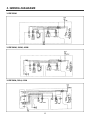
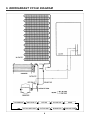
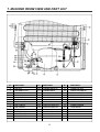
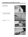
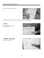
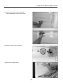
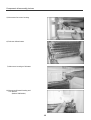
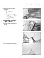
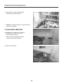
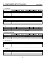
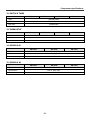
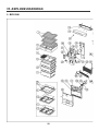
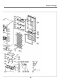
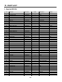
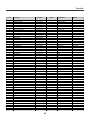
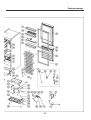
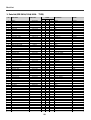
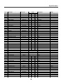
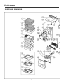
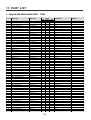
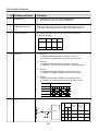
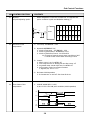
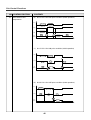
CONTENTS
1.
Specifications
..............................................................................................
1.2 Types of the approved safety standards
....................................................
3
3
2.
External drawings
3.
Wiring diagrams
4.
Name of parts
5.
Air flow diagram . . . . . . . . . . . . . . . . . . . . . . . . . . . . . . . . . . . . . . . . . . . . . . . . . . . . . . . . . . . . . . . . . . . . . . . . . . . . . . . . . . . . . . . . . . .7
6.
Refrigerant cycle diagram . . . . . . . . . . . . . . . . . . . . . . . . . . . . . . . . . . . . . . . . . . . . . . . . . . . . . . . . . . . . . . . . . . . . . . . . . . . . . 8
7.
Machine room view and part list
8.
Components disassembly pictures
9.
Components specifications . . . . . . . . . . . . . . . . . . . . . . . . . . . . . . . . . . . . . . . . . . . . . . . . . . . . . . . . . . . . . . . . . . . . . . . . . 19
5
...........................................................................................
.............................................................................................
10. Explode drawings
11. Part lists
4
.........................................................................................
..................................................................
6
9
10
...............................................................
22
.......................................................................................
....................................................................................................
12. PCB control functions
24
35
.................................................................................
13. Main PCB diagram . . . . . . . . . . . . . . . . . . . . . . . . . . . . . . . . . . . . . . . . . . . . . . . . . . . . . . . . . . . . . . . . . . . . . . . . . . . . . . . . . . . . . 42
14. Trouble Shooting
43
........................................................................................
1
1. SPECIFICATIONS
1. Specifications
Model name
ERF-331
Division
M
Refrigerant
R-134a
80gr
Blowing agent
Cooling system
Defrost system
Compressor
Rated voltage (w)
Rated input (W)
135
Lamp rated input (W)
15
Gross
Freezer
99
capacity
Refrigerator
201
(liter)
Total
300
External
Height
1706
dimension
Width
596
(mm)
Depth
624
Energy
kwh/24h
1,26
consumption class
B
Freezing capacity(kg/24h)
5.0
Star rating
* ***
Climate class
N
Net weight (kg)
61
ERF-361
A
M
90gr
90gr
ERF-391
ERF-411
A
M
A
M
90gr
90gr
90gr
90gr
C-PENTANE
Fan cool system
Automatic start & Automatic stop system
HPL25YG1-5
AC220~240V / 50Hz
135
135
135
135
135
135
15
15
15
15
15
15
93
93
93
93
114
114
223
223
253
253
254
254
316
316
346
346
368
368
1780
1780
1911
1911
2000
2000
600
600
600
600
600
600
618
618
618
618
618
618
1,29
1,28
1,30
1,29
1,33
1,32
B
B
B
B
B
B
5.0
5.0
5.0
5.0
5.0
5.0
* ***
* ***
* ***
* ***
* ***
* ***
N
N
N
N
N
N
69
69
75
75
79
79
Note) A : Electronic control type
M : Manual control type
1.2. Types of the approved safety standards
3
2. EXTERNAL DRAWINGS
1. ERF-331M
2. ERF-361A(M), 391A(M), 411A(M)
4
3. WIRING DIAGRAMS
1. ERF-331M
2. ERF-361M, 391M, 411M
3. ERF-361A, 391A, 411A
5
4. NAME OF PARTS
1. ERF-331M
1.
Shelves (The material of shelf can be changed
by model).
ERF-331, 361 series: 2 shelves.
ERF-391, 411 series: 3 shelves
2. ERF-361M, 391M, 411M
2.
Cover vegetable case (Tne material of shelf can
be changed by model).
3.
Interior light for refrigerator compartment.
4.
Multi air flow duct.
5.
Refrigerator & freezer temperature control
knob.
6.
Low temperature compartments (only ERF411A series).
7.
Vegetable case. 1 box type or 2 boxes type
(For the case of 1 box type, the Part (15) must
be deleted).
8.
Rating plate. It‘s attached in the refrigerator
compartment on the left-hand side next to the
vegetable case.
9.
Ice cube tray.
10.
Case for storing & freezing.
11.
Butter pocket.
12.
Egg pocket.
13.
Egg tray.
14.
Bottle pocket.
15.
R door pocket.
16.
Adjustable feet.
3. ERF-361A, 391A, 411A
6
5. AIR FLOW DIAGRAM
Fresh food preserving case
(Chilled case)
Used for storing fish or
meat
Case vegetable
For storing fruits or
vegetables
Air circulation in the
freezer compartment
Cold air flow comes
out from the front
hole and comes into
the lower hole in
louver
* Standard Model
7
6. REFRIGERANT CYCLE DIAGRAM
COMPRESSOR
PIPE CONN. B
SUCTION PIPE CONN.
HOT PIPE
WI-CON PIPE
DRYER
SUCTION PIPE
EVAPORATOR
CAPILLARY TUBE
8
7. MACHINE ROOM VIEW AND PART LIST
Nº
A
1
2
3
4
5
6
7
8
9
10
11
12
13
PART NAME
PIPE HOT
ABSORBER COMP.
COMPRESSOR
FIXTURE COMP.
EVAPORATOR AS
PIPE Wi-CON AS
SPECIAL SCREW E
PIPE CONN B
PIPE CHARGE
PIPE SUC. CONN
DRYER AS
ABSORBER PIPE B
ABSORBER PIPE C
BOX RELAY AS
Nº
13-1
13-1-1
13-1-2
13-1-3
13-2
13-3
13-4
13-5
13-6
13-7
13-8
14
15
16
PART NAME
HARNESS RELAY AS
HARNESS RELAY
CAPACITOR RUN AS
CABLE TIE
BOX RELAY
CABLE CLAMP
SCREW TAPPING
SWITCH P RELAY PTC
SWITCH P RELAY OL
CODE POWER AS
COVER ME HOUSING
REALY COVER
BAND REALY
CAP DRAINER
9
Nº
17
18
19
20
21
22
23
24
25
PART NAME
SCREW TRS 4X14
SPECIAL WASHER R/C
SPECIAL NUT R/C
SPECIAL WASHER
SPECIAL MASHINE
HARNESS EARTH
SPECIAL WASHER
SCREW MASHINE
CASE VAPORI
8. COMPONENTS DISASSEMBLY PICTURES
1- CONTROL PANEL
1) Remove two fixing screws.
2) Take out control panel by pulling it
Up and inserting a minus driver like
Picture shows, and move it left-right.
3) Detach F-Pcb harness, cable tie and
Switch lamp.
10
Components disassembly pictures
4) Remove 3 front and 2 upper screws
to take out base control panel.
5) Detach all connectors of M-Pcb and
take out it.
6) Remove 3 fixing screws to take out
F-Pcb.
7) Remove the door switch sliding by its
guide.
* REMARK: Disassembly system for M type models is
similar but with less components.
11
Components disassembly pictures
2- COVER MULTI-DUCT (FOR M TYPE
MODELS)
1) Remove the window by pushing lower
part upward and pulling forward.
2) Remove 3 fixing screws.
3) Pull forward with instant force.
4) Remove socket lamp harness and
timer/thermostat harness by pressing
the housing with the fingers.
12
Components disassembly pictures
5) Remove insulator multi-duct.
6) Unscrew defrost timer.
7) Disconnect defrost timer housing.
8) Take out temperature control switch
by a minus driver carefully.
13
Components disassembly pictures
9) Take out thermostat by unscrewing it.
* REMARK: Disassembly system for A type models is similar but with less components.
3 GASKET
1) Take out the gasket as shown.
2) Fix the new one.
4- FREEZER COMPARTMENT
1) Remove 2 fixing screws.
14
Components disassembly pictures
2) Remove louver FA (to prevent damages
Is better disassembly it like pictures show).
3) Remove 2 fixing screws of louver B.
4) Take out louver FB by hand.
15
Components disassembly pictures
5) Disconnect fan motor housing.
6) Take out defrost heater.
7) Disconnect housings of d-heater.
8) Disconnect Bi-metal housing and
Cut cable tie
(FOR M TYPE ONLY)
16
Components disassembly pictures
9) Take out fuse pulling out the fuse
temp fixture.
3.1 FOR REPLACE FUSE TEMP
AND D-SENSOR
1) Cut black and grey wires and take out
the fuse.
2) Join cut wires with the new fuse wires.
17
Components disassembly pictures
3) Cover joint point with insulated tape
(The best way is retractil tube).
* REMARK: For replace D-sensor in A type models, is
used the same system.
5- DOOR SWITCH ERF-331M
1) Remove the door switch out of cabinet
by inserting “-“ screw driver to the
inside of rubber packing.
*Take care not to damage the rubber
packing and divisor plate paint.
2) Remove the terminals.
18
9. COMPONENTS SPECIFICATIONS
Specification
1. COMPRESSOR
ERF-331M
ERF-361A
ERF-361M
ERF-391A
Part name
HPL25YG1-5
Part code
3956420481
ERF-391M
ERF-411A
ERF-411M
ERF-411A
ERF-411M
ERF-411A
ERF-411M
ERF-391M
ERF-411A
ERF-411M
ERF-391M
ERF-411A
ERF-411M
ERF-411A
ERF-411M
Rated voltage
220/240V 50Hz
Starting type
RSCR
Refrigerant
R-134a
2. PTC
ERF-331M
ERF-361A
ERF-361M
ERF-391A
ERF-391M
Part name
PTH490D-AS330
Part code
3817907000
3. OLP
ERF-331M
ERF-361A
ERF-361M
ERF-391A
ERF-391M
Part name
4TM213NHBYY
Part code
3817911200
4. RUNNING CAPACITOR
ERF-331M
ERF-361A
ERF-361M
ERF-391A
Part name
MP80040061
Specification
4µF, 400VAC
Part code
3010938000
5. FAN MOTOR AS
ERF-331M
ERF-361A
ERF-361M
Part name
ERF-391A
IS-2321 1DWBFO
Specification
220-240V, 50HZ, 2400RPM
Part code
3011604700
6. HEATER A AS
ERF-331M
ERF-361A
ERF-361M
Type
ERF-391A
ERF-391M
Glass tube heater
Specification
AC230V, 148W
Part code
3012807600
19
Component specifications
7. LAMP
ERF-331M
ERF-361A
ERF-361M
Type
ERF-391A
ERF-391M
ERF-411A
ERF-411M
ERF-391M
ERF-411A
ERF-411M
ERF-391M
ERF-411A
ERF-411M
ERF-391M
ERF-411A
ERF-411M
ERF-411A
ERF-411M
Pygmy
Specification
AC230V, 15W (E14)
Part code
3013600700
8. SWITCHLAMP
ERF-331M
Type
Specification
Part code
ERF-361A
ERF-361M
ERF-391A
DSSD-6
1051
250V, 0,5A
250V, 0,25A
3011721300
3018111500
9. SOCKET LAMP
ERF-331M
ERF-361A
ERF-361M
Type
ERF-391A
AJC-800
Specification
AC250V, E14
Part code
3017903900
10. FUSE TEMPERATURE
ERF-331M
ERF-361A
ERF-361M
Type
ERF-391A
DF77S
Specification
AC250V, 77 ºC
Part code
3017200420
11. SWITCH BI-METAL
ERF-331M
ERF-361A
ERF-361M
Type
ERF-391A
ERF-391M
PST-3
Specification
250V, 50˜60Hz
Part code
3018120600
20
Component specifications
12. SWITCH D TIMER
ERF-331M
ERF-361M
Type
ERF-391M
ERF-411M
JDT-MN7109D
Specification
AC250V, 50/60Hz
Part code
3018117500
13. THERMOST AT
ERF-331M
ERF-361M
ERF-391M
Type
BU-260
Specification
250V, SA
Part code
ERF-411M
3018302200
14. SENSOR R AS
ERF-361A
ERF-391A
Type
ERF-411A
NBC-K43-D21
Specification
R=0 ºC 30KΩ±3%
Part code
3012731800
15. SENSOR D AS
ERF-361A
ERF-391A
Type
NBC-K43-D21
Specification
Part code
R=0 ºC 30KΩ±3%
3012731400 (HARNESS SENSOR AS)
21
ERF-411A
10. EXPLODE DRAWINGS
1. ERF-331M
22
Explode drawings
89
23
11. PART LIST
1. Parts list (ERF-331)
NO
PART NAME
PART CODE
MODEL
1
SHELF R
3017823200
2
COVER VEGTB CASE
3011453600
3
CASE VEGTB
3011163400
2
GPPS
4
CASE ICING
3011163200
1
PP
5
CASE FD
3011163100
1
HIPS
6
CASE FB AS
3011164200
2
CASE+COVER
7
CASE FA AS
3011164100
1
CASE+COVER
8
PLATE SHELF GLASS
3014547700
1
GLASS t4.0
OPTION
9
FRAME GLASS SHELF
3012202400
1
HIPS
OPTION
10
FRAME C/CASE COVER
3012202500
1
HIPS
OPTION
11
PLATE V/CASE COVER GLASS
3014547800
1
GLASS t4.0
OPTION
12
FRAME V/CASE COVER
3012202600
1
HIPS
OPTION
13
BASE CONTROL PANEL
3010318700
1
HIPS
14
PANEL CONTROL
3014228900
1
ABS
15
CAP CONTROL PANEL A
3010902800
1
SILICON RUBBER
16
INSULATOR MULTI DUCT
3013337600
1
F-PS (0.025)
17
HARNESS THERMOSTAT
3012731500
1
18
THERMOSTAT
3018302200
1
250V 6A
19
COVER MULTI DUCT
3011453000
1
HIPS t2.0
20
SOCKET LAMP AS
3017903900
1
21
LAMP
3013600700
1
22
WINDOW LAMP
3015503300
1
23
KNOB R
3013401410
1
24
HARNESS TIMER
3012731600
1
25
SWITCH DEF TIMER
3018115700
1
26
EVAPORATOR AS
3017045700
1
27
SWITCH BI-METAL
3018120600
1
250V 5A
28
HEATER D AS
3012807600
1
GLASS HEATER+FUSE TEMP
29
BRACKET FAN MOTOR
3010615600
1
PP
30
MOTOR FAN AS
3011604700
1
IS-231 1DWBF0
31
LOUVER F B
3018911400
1
PP (411:HIPS)
32
FAN
3011801400
1
ABS /100
33
FIXTURE FAN RING
3012005400
1
SUS304 t0.5
34
LOUVER F A
3018911300
1
HIPS
35
BUSHING FAN MOTOR
3010901800
2
NR
36
ASSY CAB URT
3010086300
1
ASSY
37
HINGE *T
3012908100
2
P/O+ZN t3.2
38
SPECIAL BOLT C
3016004900
10
M5xP0.89xL16 SWCH22A
39
CAP SCREW
3010920200
1
PE-LD
40
CAP SCREW HOLE
3010920300
1
HIPS
41
SPECIAL WASHER HINGE
3016005500
3
S20C t1.0 13/7
42
SHAFT HI
3014903200
2
43
SWITCH DOOR
3018120500
1
44
HINGE *M
3012911800
1
ZNDC2, DIE CASTING
45
HINGE *U *L
3012912200
1
SPHC 3.2t
46
HINGE *U *L
3012912100
2
SPHC 3.2t
47
COVER CAB BRACKET
3011453300
1
PP
48
FOOT ADJUSTING AS
3012101800
2
PP+SPECIAL BOLT
49
CAP DRAIN HOSE
3010919700
1
NBR
50
CASE VAPORY
3011162600
1
PP
51
FIXTURE COMP
3012005300
2
SK5+ZN5-C t0.8
52
DRYER ASSY
3016802200
1
15Gr (t0.51)
53
ABSORBER COMP
3010101700
4
NR
54
BASE COMP
3010318600
1
SBHG t1.0
55
SPECIAL SCREW A
3016004300
4
M6.5xL20
56
CAPACITOR RUNNING
3010938000
1
4uF 400AC
57
SPECIAL WASHER R/C
3016006400
1
A
24
DESCRIPTION
REMARK
2
GPPS
391/411
1
GPPS
ASSY
230V 15W
GPPS
HIPS
EVA+SUC PIPE
DSD-6
DNA
Part List
NO
PART NAME
PART CODE
MODEL
58
SPECIAL NUT R/C
3016006500
1
59
SCREW MACHINE
7051401065
3
PAN 4x10 BSNI
60
HARNESS EARTH
3012735200
1
110mm
61
PIPE CHARGE
3014418200
1
DCUT1-/6xT0.6x100
62
SPECIAL WASHER
3016004700
4
/4.3 STAR
63
SWITCH P RELAY OL
3817911200
1
4TM213NHB
64
SWITCH P RELAY PTC
3817907000
1
33?(MURATA)
65
REALY BOX
3810506400
1
66
CABLE CLAMP
3818200300
1
67
HARNESS RELAY
3012731900
1
68
RELAY BOX COVER
3811401300
1
69
BAND RELAY
3816100400
1
70
COVER MECH HOUSING
3011454100
1
71
SPECIAL SCREW
3016004800
2
72
CORD POWER AS
3011343300
1
73
WI-CON ASSY
3014434500
1
74
ABSORBER PIPE C
4016C08014
2
EPDM (18g)
PIPE CONN
75
ABSORBER PIPE B
3010101900
1
IIR
PIPE SUC
76
COVER BUTTER CASE
3011453500
1
GPPS
77
CASE BUTTER
3011163500
1
GPPS
78
CASE EGG
3011163600
1
PP
79
POCKET EGG
3019014100
1
HIPS
80
POCKET BOTTLE
3019014200
1
HIPS
81
GUIDE POCKET
3012510200
1
PP
82
POCKET R DOOR
3019014300
1
HIPS
83
ASSY R DOOR URT
3010086400
1
ASSY
84
GASKET R DOOR AS
3012306610
1
PVC+MAGNET
85
CAP DOOR BUSSHING
3010918300
1
PP
86
ASSY F DOOR URT
3010086500
1
ASSY
87
GASKET F DOOR AS
3012306510
1
PVC+MAGNET
88
TEMPERATURE FUSE
3017200420
1
89
COMPRESSOR
3956420481
1
25
DESCRIPTION
REMARK
M8
earth:4
HIPS
CP 2PIN
HPL25Y61-5
Explode drawings
2. ERF-361A, 391A, 411A
26
Explode drawings
96
27
Part List
1. Parts list (ERF-361A/391A/411A
NO
PART NAME
TYPE)
PART CODE
MODEL
361A
391A
411A
DESCRIPTION
REMARK
GPPS
391/411
1
SHELF R
3017823200
1
2
2
2
COVER CHILLED CASE
3011453400
1
1
1
3
CASE CHILD
3011163300
1
1
1
GPPS
4
COVER VEGTB CASE
3011453600
1
1
1
GPPS
5
CASE VEGTB
3011163400
2
2
2
GPPS
6
CASE ICING
3011163200
1
1
1
PP
7
CASE FD
3011115911
1
1
1
HIPS
8
CASE FB (411:CASE FC)
3011115310
2
2
-
HIPS
3011115410
-
-
2
HIPS
HIPS
9
CASE FA
3011115202
1
1
1
10
PLATE SHELF GLASS
3014547700
1
1
1
GLASS t4.0
11
FRAME GLASS SHELF
3012202400
1
1
1
HIPS
OPTION
12
FRAME C/CASE COVER
3012202500
1
1
1
HIPS
OPTION
13
PLATE V/CASE COVER GLASS
3014547800
1
1
1
GLASS t4.0
OPTION
14
FRAME V/CASE COVER
3012202600
1
1
1
HIPS
OPTION
15
BASE CONTROL PANEL
PAGE 34
1
1
1
HIPS
16
CABLE TIE
4016N03281
1
1
1
17
PCB MAIN AS
3014397060
1
1
1
18
HARNESS F PCB
3012718300
1
1
1
19
PCB F AS
3014372130
1
1
1
20
WINDOWS LED
3015503400
1
1
1
SILICON RUBBER
21
PANEL CONTROL
PAGE 34
1
1
1
ABS
22
CAP CONTROL PANEL A
PAGE 34
1
1
1
SILICON RUBBER
23
SWITCH LAMP
3018111500
1
1
1
250V 0,25A
24
SOCKET LAMP AS
3017903900
1
1
1
25
COVER MULTI DUCT
3011451900
1
-
-
3011452100
-
1
1
HIPS t2.0
26
INSULATOR MULTI DUCT
3016637000
1
-
-
F-PS
3013337200
-
1
1
F-PS
27
LAMP
3013600700
1
1
1
230V 15W
28
WINDOW LAMP
3015503300
1
1
1
29
SENSOR R AS
3012731800
1
1
1
30
EVAPORATOR AS
3017045600
1
1
1
EVA+SUC PIPE
31
HEATER D AS
3012807600
1
1
1
GLASS HEATER+FUSE TEMP
32
BRACKET FAN MOTOR
3010615600
1
1
1
PP
33
MOTOR FAN AS
3011604700
1
1
1
IS-231 1DWBF0
34
LOUVER F B
3018905500
1
1
-
PP (411:HIPS)
3018905600
-
-
1
PP (411:HIPS)
3011801400
1
1
1
ABS /100
ASSY
HIPS t2.0
GPPS
35
FAN
36
FIXTURE FAN RING
3012005400
1
-
-
SUS304 t0.5
37
LOUVER F A
3018905300
1
1
-
HIPS
3018905400
-
-
1
HIPS
2
2
NR
38
BUSHING FAN MOTOR
3010901800
2
39
ASSY CAB URT
3010071001
1
-
-
ASSY
3010071011
-
1
-
ASSY
3010071021
-
-
1
ASSY
40
HINGE *T
3012908100
2
2
2
P/O+ZN t3.2
41
SPECIAL BOLT C
3016004900
10
10
10
M5xP0.89xL16 SWCH22A
42
CAP SCREW
PAGE 34
1
1
1
PE-LD
43
CAP SCREW HOLE
3010920300
1
1
1
HIPS
44
SPECIAL WASHER HINGE
3016005500
3
3
3
S20C t1.0 13/7
45
SHAFT HI
3014903200
2
2
2
46
HINGE *M
3012908000
1
1
1
DIE CASTING
47
HINGE *U
3012908200
2
2
2
P/O+ZN t3.2
48
COVER CAB BRACKET
PAGE 34
1
1
1
HIPS
49
FOOT ADJUSTING AS
3012101800
2
2
2
PP+SPECIAL BOLT
50
CAP DRAIN HOSE
3010919700
1
1
1
NBR
28
OPTION
Specification
NO
PART NAME
PART CODE
MODEL
361A
391A
DESCRIPTION
REMARK
411A
51
CASE VAPORY
3011162600
1
1
1
PP
52
FIXTURE COMP
3012005300
2
2
2
SK5+ZN5-C t0.8
53
DRYER ASSY
3016802200
1
1
1
15Gr (t0.51)
54
ABSORBER COMP
3010101700
4
4
4
NR
55
BASE COMP
3010318600
1
1
1
SBHG t1.0
56
SPECIAL SCREW A
3016004300
4
4
4
M6.5xL20
57
CAPACITOR RUNNING
3010938000
1
1
1
4uF 400AC
58
SPECIAL WASHER R/C
3016006400
1
1
1
A
59
SPECIAL NUT R/C
3016006500
1
1
1
M8
60
SCREW MACHINE
7051401065
3
3
3
PAN 4x10 BSNI
61
HARNESS EARTH
3012735200
1
1
1
110mm
62
PIPE CHARGE
3014418200
1
1
1
DCUT1-/6xT0.6x100
63
SPECIAL WASHER
3016004700
4
4
4
/4.3 STAR
64
SWITCH P RELAY OL
3817911200
1
1
1
4TM213NHB
65
SWITCH P RELAY PTC
3817907000
1
1
1
33?(MURATA)
66
RELAY BOX
3810506400
1
1
1
67
CABLE CLAMP
3818200300
1
1
1
68
HARNESS RELAY
3012731900
1
1
1
69
RELAY BOX COVER
3811401300
1
1
1
70
BAND RELAY
3816100400
1
1
1
71
COVER MECH HOUSING
3011454100
1
1
1
72
SPECIAL SCREW
3016004800
2
2
2
73
CORD POWER AS
3011343300
1
1
1
74
WI-CON ASSY
3014434500
1
1
-
3014434600
-
-
1
75
ABSORBER PIPE C
4016008014
2
2
2
EPDM (18g)
PIPE CONN
76
ABSORBER PIPE B
3010101900
1
1
1
IIR
PIPE SUC
77
POCKET BUTTER
3019008720
1
1
1
HIPS
78
CASE EGG
3011163600
2
2
2
PP
79
POCKET EGG
3019008701
1
1
1
HIPS
80
GUIDE POCKET
3012510200
1
1
1
PP
81
POCKET BOTTLE A
3019008600
1
1
1
HIPS
82
POCKET R DOOR
3019013600
1
1
1
HIPS
CP 2PIN
3019009500
FOR SUPERIOR CLASS
HIPS
GUIDE BOTTLE SUPPORT B
3012508000
FOR SUPERIOR CLASS
SUPERIOR POCKET R DOOR
3019008710
FOR SUPERIOR CLASS
HIPS
GUIDE BOTTLE SUPPORT C
3012508010
FOR SUPERIOR CLASS
ASSY R DOOR URT
84
GASKET R DOOR AS
3012306800
-
1
1
PVC+MAGNET
85
CAP DOOR BUSSHING
PAGE 34
1
1
1
PP
86
ASSY F DOOR URT
PAGE 34
1
-
-
ASSY
PAGE 34
-
1
1
ASSY
3012306500
1
1
-
PVC+MAGNET
3012306700
-
-
1
PVC+MAGNET
GASKET F DOOR AS
SUPERIOR
SUPERIOR
STEAL
83
87
earth:4
HIPS
POCKET BOTTLE B
PAGE 34
DNA
1
-
-
ASSY
PAGE 34
-
1
1
ASSY
3012306600
1
-
-
PVC+MAGNET
88
CAP HANDLE
PAGE 34
1
1
1
HIPS
89
COVER DOOR CAP *L
PAGE 34
2
2
2
ABS
OPTION
90
COVER DOOR CAP *R
PAGE 34
2
2
2
ABS
OPTION
91
HANDLE *T
PAGE 34
1
1
1
PBT
OPTION
92
SPECIAL SCREW D
3016004810
4
4
4
T2 FLT 4x16 PAINTING
OPTION
93
HANDLE *U
PAGE 34
1
1
1
PBT
OPTION
94
TEPERATURE FUSE
3017200420
1
1
1
95
D-SENSOR
3012733910
1
1
1
96
COMPRESSOR
3956420481
1
1
1
29
HPL25Y61-5
OPTION
SUPERIOR
Explode drawings
3. ERF-361M, 391M, 411M
30
Explode drawings
96
31
11. PA RT LIST
1. Parts list (ERF-361M/391M/411M
NO
PART NAME
TYPE)
PART CODE
MODEL
391M
2
411M
2
1
1
DESCRIPTION
REMARK
GPPS
391/411
1
SHELF R
3017823200
361M
1
2
COVER CHILLED CASE
3011453400
1
3
CASE CHILD
3011163300
1
1
1
GPPS
4
COVER VEGTB CASE
3011453600
1
1
1
GPPS
5
CASE VEGTB
3011163400
2
2
2
GPPS
6
CASE ICING
3011163200
1
1
1
PP
7
CASE FD
3011115911
1
1
1
HIPS
8
CASE FB (411:CASE FC)
3011115310
2
2
-
HIPS
3011115410
-
-
2
HIPS
HIPS
9
CASE FA
3011115202
1
1
1
10
PLATE SHELF GLASS
3014547700
1
1
1
GLASS t4.0
11
FRAME GLASS SHELF
3012202400
1
1
1
HIPS
OPTION
12
FRAME C/CASE COVER
3012202500
1
1
1
HIPS
OPTION
13
PLATE V/CASE COVER GLASS
3014547800
1
1
1
GLASS t4.0
OPTION
14
FRAME V/CASE COVER
3012202600
1
1
1
HIPS
OPTION
15
BASE CONTROL PANEL
PAGE 34
1
1
1
HIPS
16
PANEL CONTROL
PAGE 34
1
1
1
ABS
17
CAP CONTROL PANEL A
PAGE 34
1
1
1
SILICON RUBBER
18
SWITCH LAMP
3018111500
1
1
1
250V 0,25A
19
HARNESS LAMP SW
3012717020
1
1
1
20
INSULATOR MULTI DUCT
3013337100
1
-
-
F-PS
3013373000
-
1
1
F-PS
3012731500
1
1
1
21
HARNESS THERMOSTAT
22
THERMOSTAT
3018302200
1
1
1
23
COVER MULTI DUCT
3011452000
1
-
-
HIPS t2.0
3011452300
-
1
1
HIPS t2.0
250V 6A
24
SOCKET LAMP AS
3017903900
1
1
1
25
LAMP
3013600700
1
1
1
26
WINDOW LAMP
3015503300
1
1
1
27
KNOB R
3013401410
1
1
1
28
HARNESS TIMER
3012731600
1
1
1
29
SWITCH DEF TIMER
3018115700
1
1
1
30
EVAPORATOR AS
3017045600
1
1
1
31
SWITCH BI-METAL
3018120600
1
1
1
250V 5A
32
HEATER D AS
3012807600
1
1
1
GLASS HEATER+FUSE TEMP
33
BRACKET FAN MOTOR
3010615600
1
1
1
PP
34
MOTOR FAN AS
3011604700
1
1
1
IS-231 1DWBF0
35
LOUVER F B
3018905500
1
1
-
PP (411:HIPS)
3018905600
-
-
1
ASSY
PP (411:HIPS)
3011801400
1
1
1
ABS /100
230V 15W
GPPS
HIPS
EVA+SUC PIPE
36
FAN
37
FIXTURE FAN RING
3012005400
1
-
-
SUS304 t0.5
38
LOUVER F A
3018905300
1
1
-
HIPS
3018905400
-
-
1
HIPS
2
2
NR
39
BUSHING FAN MOTOR
3010901800
2
40
ASSY CAB URT
3010071031
1
-
-
ASSY
3010071041
-
1
-
ASSY
3010071051
-
-
1
ASSY
41
HINGE *T
3012908100
2
2
2
P/O+ZN t3.2
42
SPECIAL BOLT C
3016004900
10
10
10
M5xP0.89xL16 SWCH22A
43
CAP SCREW
PAGE 34
1
1
1
PE-LD
44
CAP SCREW HOLE
3010920300
1
1
1
HIPS
45
SPECIAL WASHER HINGE
3016005500
3
3
3
S20C t1.0 13/7
46
SHAFT HI
3014903200
2
2
2
47
HINGE *M
3012908000
1
1
1
DIE CASTING
48
HINGE *U
3012908200
2
2
2
P/O+ZN t3.2
49
COVER CAB BRACKET
PAGE 34
1
1
1
HIPS
50
FOOT ADJUSTING AS
3012101800
2
2
2
PP+SPECIAL BOLT
32
OPTION
Part List
NO
PART NAME
PART CODE
MODEL
DESCRIPTION
361M
391M
411M
REMARK
51
CAP DRAIN HOSE
3010919700
1
1
1
52
CASE VAPORY
3011162600
1
1
1
PP
53
FIXTURE COMP
3012005300
2
2
2
SK5+ZN5-C t0.8
54
DRYER ASSY
3016802200
1
1
1
15Gr (t0.51)
55
ABSORBER COMP
3010101700
4
4
4
NR
56
BASE COMP
3010318600
1
1
1
SBHG t1.0
57
SPECIAL SCREW A
3016004300
4
4
4
M6.5xL20
58
CAPACITOR RUNNING
3010938000
1
1
1
4uF 400AC
59
SPECIAL WASHER R/C
3016006400
1
1
1
A
60
SPECIAL NUT R/C
3016006500
1
1
1
M8
61
SCREW MACHINE
7051401065
3
3
3
PAN 4x10 BSNI
62
HARNESS EARTH
3012735200
1
1
1
110mm
63
PIPE CHARGE
3014418200
1
1
1
DCUT1-/6xT0.6x100
64
SPECIAL WASHER
3016004700
4
4
4
/4.3 STAR
65
SWITCH P RELAY OL
3817911200
1
1
1
4TM213NHB
66
SWITCH P RELAY PTC
3817907000
1
1
1
33?(MURATA)
67
REALY BOX
3810506400
1
1
1
68
CABLE CLAMP
3818200300
1
1
1
69
HARNESS RELAY
3012731900
1
1
1
70
RELAY BOX COVER
3811401300
1
1
1
71
BAND RELAY
3816100400
1
1
1
72
COVER MECH HOUSING
3011454100
1
1
1
73
SPECIAL SCREW
3016004800
2
2
2
74
CORD POWER AS
3011343300
1
1
1
75
WI-CON ASSY
3014434500
1
1
-
3014434600
-
-
1
76
ABSORBER PIPE C
4016007014
2
2
2
EPDM (18g)
PIPE CONN
77
ABSORBER PIPE B
3010101900
1
1
1
IIR
PIPE SUC
78
POCKET BUTTER
3019008720
1
1
1
HIPS
79
CASE EGG
3011163600
2
2
2
PP
80
POCKET EGG
3019008701
1
1
1
HIPS
81
GUIDE POCKET
3012510200
1
1
1
PP
82
POCKET BOTTLE A
3019008600
1
1
1
HIPS
83
POCKET R DOOR
3019013600
1
1
1
HIPS
84
85
NBR
earth:4
HIPS
CP 2PIN
POCKET BOTTLE B
3019009500
FOR SUPERIOR CLASS
HIPS
SUPERIOR
GUIDE BOTTLE SUPPORT B
3012508000
FOR SUPERIOR CLASS
STEAL
SUPERIOR
SUPERIOR POCKET R DOOR
3019008710
FOR SUPERIOR CLASS
HIPS
SUPERIOR
GUIDE BOTTLE SUPPORT C
3012508010
FOR SUPERIOR CLASS
STEAL
SUPERIOR
ASSY R DOOR URT
PAGE 34
1
-
-
ASSY
PAGE 34
-
1
1
ASSY
PVC+MAGNET
GASKET R DOOR AS
3012306600
1
-
-
3012306800
-
1
1
PVC+MAGNET
1
1
PP
86
CAP DOOR BUSSHING
PAGE 34
1
87
ASSY F DOOR URT
PAGE 34
1
-
-
ASSY
PAGE 34
-
1
1
ASSY
3012306500
1
1
-
PVC+MAGNET
3012306700
-
-
1
PVC+MAGNET
88
DNA
GASKET F DOOR AS
89
CAP HANDLE
PAGE 34
1
1
1
HIPS
90
COVER DOOR CAP *L
PAGE 34
2
2
2
ABS
OPTION
91
COVER DOOR CAP *R
PAGE 34
2
2
2
ABS
OPTION
92
HANDLE *T
PAGE 34
1
1
1
PBT
OPTION
93
SPECIAL SCREW D
3016004810
4
4
4
T2 FLT 4x16 PAINTING
OPTION
94
HANDLE *U
PAGE 34
1
1
1
PBT
OPTION
95
TEMPERATURE FUSE
3017200420
1
1
1
1
1
1
96
COMPRESSOR
3956420481
33
HPL25Y61-5
OPTION
Part List
Part list of colour components (ERF-361A/M,ERF-391A/M,ERF-411A/M)
WHITE
NO
PART NAME
PART CODE
MODEL
361
391
DESCRIPTION
REMARK
411
1
CONTROL PANEL A
3014204800
1
1
1
ABS
electronic
2
CONTROL PANEL M
3014204950
1
1
1
ABS
mechanical
3
BASE CONTROL PANEL
3010312900
1
1
1
4
REFRIGERATOR DOOR (310)
3010075201
1
5
REFRIGERATOR DOOR (340-370)
3010075213
6
FREEZER DOOR (310-340)
3010075303
7
FREEZER DOOR (370)
3010075313
8
HANDLE *F
3012610100
1
9
HANDLE *R
3012610200
1
10
COVER DOOR CAP *L
3011437000
11
COVER DOOR CAP *R
12
CAP HANDLE
13
HIPS
URT FORMING ( CO-LAMINAR )
1
1
URT FORMING ( CO-LAMINAR )
1
URT FORMING ( CO-LAMINAR )
1
1
PBT
1
1
PBT
2
2
2
ABS
3011437010
2
2
2
ABS
3010910010
4
4
4
HIPS
CAP SCREW
3010920200
1
1
1
HIPS
14
CAP DOOR BUSHING
3010918300
1
1
1
PP
15
CAP CONTROL PANEL
3010902810
1
1
1
SILICON RUBBER
16
COVER CAB BRACKET
3011433320
1
1
1
HIPS
1
1
URT FORMING ( CO-LAMINAR )
SILVER
NO
PART NAME
PART CODE
MODEL
361
391
DESCRIPTION
REMARK
411
1
CONTROL PANEL A
3014204940
1
1
1
ABS
electronic
2
CONTROL PANEL M
3014204970
1
1
1
ABS
mechanical
3
BASE CONTROL PANEL
3010312910
1
1
1
4
REFRIGERATOR DOOR (310)
3010074601
1
5
REFRIGERATOR DOOR (340-370)
3010075211
6
FREEZER DOOR (310-340)
3010075301
7
FREEZER DOOR (370)
3010075311
8
HANDLE *F
3012610120
1
9
HANDLE *R
3012610220
1
10
COVER DOOR CAP *L
3011437040
11
COVER DOOR CAP *R
12
CAP HANDLE
13
HIPS
URT FORMING ( CO-LAMINAR )
1
1
URT FORMING ( CO-LAMINAR )
1
URT FORMING ( CO-LAMINAR )
1
1
PBT
1
1
PBT
2
2
2
ABS
3011437050
2
2
2
ABS
3010910010
4
4
4
HIPS
CAP SCREW
3010920210
1
1
1
HIPS
14
CAP DOOR BUSHING
3010918310
1
1
1
PP
15
CAP CONTROL PANEL
3010902810
1
1
1
SILICON RUBBER
16
COVER CAB BRACKET
3011433320
1
1
1
HIPS
1
1
URT FORMING ( CO-LAMINAR )
INOX (DARK GRAY)
NO
PART NAME
PART CODE
APPLY MODEL
361
391
DESCRIPTION
REMARK
411
1
CONTROL PANEL A
3014204960
1
1
1
ABS
electronic
2
CONTROL PANEL M
3014204990
1
1
1
ABS
mechanical
3
BASE CONTROL PANEL
3010312910
1
1
1
4
REFRIGERATOR DOOR (310)
3010074602
1
5
REFRIGERATOR DOOR (340-370)
3010075212
6
FREEZER DOOR (310-340)
3010075302
7
FREEZER DOOR (370)
3010075312
8
HANDLE *F
3012610110
1
9
HANDLE *R
3012610210
1
10
COVER DOOR CAP *L
3011437020
11
COVER DOOR CAP *R
12
CAP HANDLE
13
HIPS
URT FORMING ( INOX )
1
1
URT FORMING ( INOX )
1
URT FORMING ( INOX )
1
1
PBT
1
1
PBT
2
2
2
ABS
3011437030
2
2
2
ABS
3010910010
4
4
4
HIPS
CAP SCREW
3010920210
1
1
1
HIPS
14
CAP DOOR BUSHING
3010918310
1
1
1
PP
15
CAP CONTROL PANEL
3010902810
1
1
1
SILICON RUBBER
16
COVER CAB BRACKET
3011433310
1
1
1
HIPS
1
34
1
URT FORMING ( INOX )
12. PCB CONTROL FUNCTIONS
PCB SERVICE MANUAL OF ELECTRONIC CONTROL TYPE
Model: ERF-361A/391A/411A
1. How to use the panel
NO CONTROL FUNCTION
CONTENTS
1
1)
In the initial Operation, refrigerator default temp is in MID position
2)
Freezer and Refrigerator LED are on with red color
1)
VAC ON: When the comp is controlled by VAC on/off condition
2)
SUPER ON: When the comp is controlled by SUPER on/off condition
3)
FREEZER LED
GREEN ON: When the freezer temp. is OK(less than -5deg
at D sensor)
RED ON: When the freezer temp. is not good
N.G condition (1 or 2)
1- More than -5 deg at D-sensor when comp. switches Off
2- More than -5 deg when comp. is running for 240 min.
cf. Error display
RED LED ON/OFF one time: D1 ERROR
It is D sensor error for open or short
RED LED ON/OFF two times: D2 ERROR
D2 Error happens when system is in defrost position for
80 min (heater doesn’t work).
This is “Defrost error”.
4)
REFRIGERATOR LED
GREEN ON: When the refrigerator temp. is OK(-7~10 deg)
RED ON: When the refrigerator temp. is not good
N.G condition (1 and 2)
1- More than 10 deg or less than -7 deg at R-sensor
2- More than 10 deg when comp. is running for 240 min.
cf. Error display
RED LED ON/OFF one time: R1 ERROR
It is R sensor error for open or short
RED LED ON/OFF two times: RT ERROR
It is RT sensor error for open or short
5)
LOW ON: When comp is controlled by LOW on/off condition
6)
MID ON: When the comp is controlled by MID on/off condition
2
Initial Operation
PANEL DISPLAY
35
Pcb Control Functions
NO CONTROL FUNCTION
CONTENTS
2
PANEL DISPLAY
7)
HIGH ON: When the comp is controlled by HIGH on/off condition
3
Refrigerator Temperature
Control
1)
Temperature can be controlled by 5 steps with the refrigerator
temperature button.
VAC
SUPER
LOW
MID
HIGH
VAC
2)
Refrigerator control on/off temperature
1- MID OFF point: -0,5ºC
2- ON /OFF DIFF: 4ºC
3- STEP DIFF (LOW-MID-HIGH): 3 deg
1)
Determination of defrost mode
1- Accumulated running time of compressor
2- Operation ration of compressor
3- Total time (on time + off time of compressor)
2)
Starting condition of Defrost mode
1- When accumulated running time of comp is 12 hours
2- Check after accumulated running time of comp. is 10
hours, if operation ration of compressor is more than 70%
then defrost mode starts.
3-
Finally, when total time is more than 60 hours,
then, defrost modestarts.
4
Determination of defrost
36
Pcb Control Functions
NO CONTROL FUNCTION
5
Flow chart for
Determination of defrost
6
Defrost Mode
CONTENTS
1)
Start: By determination defrost condition
start
10 hours
12 hours
Accumulated runng time of compressor
2)
FLOW
HEATER
PAUSE(6min.)
CONTROL
1-
HEATER
* ON - When defrost condition is started.
* OFF - When D-sensor is more than 10 deg
If D1 ERROR exists, Heater off by Time (30 min)
* D2 ERROR: 80 min in defrost position. (defrost problem)
2-
PAUSE
* Time: 6 minutes minimum after defrost, all devices are off
(hts, comp, fan)
* Forced defrost
1) Start: Temp control SW is pushed for 10 sec continuously
2) Flow: The flow is same as the general defrost flow
3) Purpose: To check defrost current of HTR in mass product line, etc
4) Though D-sensor is more than 10 deg, HTR is on at least for 30 sec
37
Pcb Control Functions
NO CONTROL FUNCTION
CONTENTS
7
Linitial Defrost
1)
2)
8
COMP Restart prevent
1) RT-S≤24: The comp can't be on within 30 min after comp. off
2) RT-S>25: The comp can't be on within 6 min after comp. off
9
Control in R1 error
In R sensor open/short error, Comp. and fan are controlled
by time as following:
10
Error code
1)
D1 error
1- Display: Freezer red LED is on and off one time
2- Condition: It happens when D sensor is open or short
2)
D2 error
1- Display: Freezer red LED is on and off two times
2- Condition: 80 min in defrost position. (defrost problem)
3)
R1 error
1- Display: Refrigerator red LED is on and off one time
2- Condition: It happens when R sensor is open or short
4)
RT error
1- Display: Refrigerator red LED is on and off two times
2- Condition: It happens when RT sensor is open or short
When Power is on, Check the D-SENSOR temp.
Condition: Less than 3.5 deg for D-SENSOR
Display contents
LED on/off Output
D1 ERROR
D2 ERROR
R1 ERROR
R2 ERROR
11
SUPER option
PURPOSE: Protection of OVER-COOL in CRISP
CONTROL
Application
(M-PCB)
Nº
ON
Micom inout
Voltage (6PIN)
Etc.
OFF
R16
R20
R19
J15
7 PIN
MICOM
1
-0.5ºC -4.5ºC
-
0V
Default
2
0.53ºC -3.5ºC
J6 cut
2.5 V
1.0 deg
3
1.5ºC -2..5ºC
J6, R29 cut
5V
2.0 deg
CC11
38
Pcb Control Functions
NO CONTROL FUNCTION
CONTENTS
12
-
R-sensor
off point adjusting option
When refrigerator is over-cool or weak-cool, it is adjusted the
option condition by R42 and R43(after deleting j7)
R42
R41
R43
13
14
Functions of low
temperature
Time charts of low
temperature
8 PIN
J7
MICOM
CC16
Micom
input
(V)
0V
1.0V
1.5V
2.0V
2.5V
3.7V
5.0
Off
point
variation
(deg)
-0.5 ºC
1.0
2.0
3.0
1.0
2.0
3.0
R42,
R43
(KG)
default
R42:40
R43:10
R42:23.3 R42:153 R42:10
R43:10 R43:10 R43:10
R42:3.5
R43:10
R42:10
R43:–
1)
Low temp.: RT SENSOR ≤ 24ºC
2)
Hysteresis DIFFERENCE: 1ºC
1- Mode of low temp. : RT SENSOR ≤ 24ºC
2- Mode of general temp.: RT SENSOR ≥ 25ºC
3- Mode of just before control : 24≤RT-S<25ºC
ex) 1- Mode of general control when is arriving to 24ºC
2- Mode of low control when is arriving to 25ºC
3)
Control
1- When comp. is on, R-s HTR is off
2- The comp can't be on whiting 30 min after comp. off
3- At general temp. Mode of RT error, R-s HTR is off
4- At low temp. mode, R-s off point increase
2 degrees (ex) -0.5 to 1.5 C
4)
R-s heater initial Operation
1- R-s heater turn on and off four times for 8 sec.
1. LOW RT MODE (RT-S ≤24ºC )
A) D-S≤3.5ºC & R-S ON point condition (Initial operation)
R-S
OFF POINT
ON POINT
Comp
COMP OFF
COMP ON
HTR ON
HTR
OFF
6min
6min
Pausa
COMP OFF
R-S
Heater
HTR ON
39
24min ON
OFF
Pcb Control Functions
NO CONTROL FUNCTION
CONTENTS
15
B)
Time charts of low
temperature
D-S≤3.5ºC & R-S OFF point condition (Initial operation)
R-S
Comp
ON POINT
OFF POINT
COMP OFF
COMP ON
HTR ON
HTR
OFF
6min
6min
Pausa
COMP OFF
OFF
24min ON
R-S
Heater
HTR ON
C) D-S≤3.5ºC & R-S ON point condition (Initial operation)
R-S
OFF POINT
ON POINT
Comp
OFF
ON
OFF
R-S
Heater
OFF
6min
24 min ON
6min
COMP OFF
COMP OFF
D) D-S>3.5ºC & R-S OFF point condition (Initial operation)
R-S
ON POINT
Comp
OFF POINT
OFF
OFF
ON
6min
R-S
Heater
24 ºBON
COMP ON
40
COMP OFF
COMP ON
Pcb Control Functions
NO CONTROL FUNCTION
CONTENTS
15
E)
Time charts of low
temperature
General mode of Low temp. (RT≤24ºC)
R-S
Comp
R-S
Heater
6min
ON POINT
OFF POINT
OFF POINT
COMP OFF
COMP ON
COMP OFF
25min ON
6min
COMP ON
25min ON
COMP ON
COMP OFF
F) General MODE (RT≥25ºC): deleting low temp function
R-S
Comp
ON POINT
OFF POINT
OFF POINT
COMP OFF
COMP ON
COMP OFF
R-S
Heater
COMP ON
41
COMP OFF
COMP ON
13. MAIN PCB DIAGRAM
42
14. TROUBLE SHOOTING
1. TROUBLE SHOOTING PROCEDURE OF THE BREAKDOWN
SYMPTOM
CHECK POINT
CAUSE
ACTION
LAMP OFF COMP OFF
Power receptable
power plug
connectors
Power failure
Connection is not good
Housing connector bad assy, with URT, terminals bent
Adjust
Adjust
FAN ON COMP OFF
Comp
PTC relay
running capacitor (R/C)
Short circuit on coil
Bad connection, bad assembled
Bad connection, bad assembled
Replace comp
Adjust
Adjust
LAMP OFF COMP ON
Component
Door switch
Lamp broken or bad assy
Door switch broken or bad assy
replace it
Adjust
FAN OFF COMP ON
Component
connectors
Fan motor broken, fan obstruction replace it
Housing connector bad assy, with URT, terminals bent
Adjust
DEFROST PROBLEMS
Heater
fuse
d-sensor/bi-metal
connectors
M-pcb
Timer
Component broken
broken (find broke down reason)
incorrect open/close temperature
Housing connectors bad assy, with URT, terminals bent
htr relay broken
timer broken or bad connection
replace it
replace it
replace it
adjust
replace it
Adjust
UNDERCOOLING
Temperature control
closing/opening door
Food storage conditions
Lamp
The control button setting is not proper
Closing/opening door is too frequent, or door is open
Excesive storage
Hot food has been stored
Food close outlet air ducts
Ref is located under direct sun light or heat.
Surrounding is blocked (no gap between walls)
Compressor, sensor, thermostat problems
Air ducts obstruction
Fan broken or obstructed
Low charge
Gas leak
Lamp always on because door switch problems
set temp
close door
Arrange
Prevent this
Reorganizate food
Move it
Move it
General inspection
Clean and repair
Replace it
Recharge
Repair/recharge
Adjust
Temperature control
Food location
R-sensor,thermostat
Chilled case
The control button setting is not proper
The wet food is placed in front of the outlet of the duct
Componet broken or disadjusted
(Chilled case has 0ºC under specification)
set temp
Reorganizate food
replace
Food location
Location setting
Electric problems
Air circulation
Fan
Refrigerant
OVER COOLING
CONFIRMATION PROCEDURE ON REFRIGERANT INSUFFICIENT
SYMPTOM
DECISION
REPAIRS
Complete leaking
Remove louver a and b. No frost will be produced at the inlet of evaporator after
passing approximately 4 minute operation of the comp
-
Refrigerant insuficient
1) Frost condition: frost condition in the inlet pipe is extremely different from the
outlet pipe.
2) Measurement of the temperature: When the inside temperature is stable, a
5ºC temperature difference occurs between the inlet pipe and the outlet pipe.
-
43
Check for a
leakage after
vacuumming
Inject proper
amount of
refrigerant