1
PCC-III Controller
Instruction Manual
Instruction Manual
Part Number:
90082
Revision 2.3
1/13/03
Preferred Instruments
A Division of Preferred Utilities Mfg. Corp.
31-35 South St., Danbury, CT 06810
Ph: 203-743-6741 Fax: 203-798-7313
preferred-mfg.com
WARNING
The PCC-III is commonly used to control potentially dangerous Combustion and
Chemical Processes.
Only qualified Instrument Engineers or Senior Technicians that have read this entire
manual, and are familiar with all aspects of the Process being controlled should attempt
to re-configure the Blockware Control Logic contained in the memory of a PCC III
Controller.
VERIFY THAT THE PROCESS BEING CONTROLLED HAS BEEN SAFELY SECURED,
ISOLATED, OR BYPASSED (AS REQUIRED BY THE SITE CONDITIONS) BEFORE
MODIFYING ANY OF THE BLOCKWARE DATA IN ANY BLOCK IN THE PCC-III MEMORY.
FAILURE TO DO SO CAN RESULT IN EQUIPMENT DAMAGE, INJURY, OR DEATH.
Note: Rev 2.3 Instruction Manual changes are indicated by a vertical line in the left margin.
Summary of Rev 2.2 Changes:
Added UL508 screw tightening Caution Note.
Enhanced the Retentive Memory Comments and Specifications.
Corrected Spare Parts part number errors.
Revised OPLR Function description to reflect ROM changes.
Added “Installing Front Panel Legends” section.
Added “Supported Modbus Functions” section.
Summary of Rev 2.3 Changes:
F83 TOUT revised per ROM 3.04
F84 TCODE added per ROM 3.04
F100 TTRIP added per ROM 3.04
Table of Contents
Introduction
Section 1
Product Overview
Product Description................................................. 2
Features .................................................................. 2
Benefits.................................................................... 2
Distributed Control System Concepts...................... 3
Analog and PLC Control Functions ......................... 3
Configuration Concepts ........................................... 3
Com-Link Data Highway Concepts.......................... 3
Blockware Concepts................................................ 4
Blocks............................................................... 4
Library of Functions.......................................... 4
Any-Function-Any-Block................................... 4
Reusable Functions.......................................... 4
Softwiring.......................................................... 4
Spec ial Option Card and Special ”Function Block”
Capabilities .............................................................. 5
Multiple F(x)...................................................... 5
Learn Mode ...................................................... 5
Boiler Efficiency................................................ 5
Service Manual (option card)............................ 5
Triac Output for Electric Actuators (option cards)
......................................................................... 5
Steam Flow Pressure Compensation ............... 5
Gas Flow Pressure/Temperature Compensation5
High Temperature Hot Water (HTHW) BTU/Hr
Computation......................................................5
Drum Level Pressure Vs. Density Compensation
..........................................................................6
Oxygen Sensor Control/Signal Conversion
(option card)......................................................6
Relay Output Channels.....................................6
“OPLR” Stack Exit Correlation for EPA Opacity
Monitors ............................................................6
Flow Totalization ...............................................6
PCC III Loop Controller Model Number....................7
Option Board Input / Output Expansion Examples: ..7
Spare Parts List........................................................8
PCC-III Specifications ..............................................9
Mechanical: .......................................................9
Environmental: ..................................................9
Performance:.....................................................9
Operator Control Panel: ....................................9
Electrical: ..........................................................9
Input/Output (Standard – no option cards):.......9
Communications ...............................................9
Section 2
Installation
Option Board Descriptions .........................................1
Mounting Overview....................................................2
Mounting Overview....................................................2
NEMA 13 / IP65 Environment....................................2
Ambient Temperature................................................2
Rear Access ..............................................................2
Mounting....................................................................2
PCC III Dimensions ...............................................3
Panel Cutout Dimensions ......................................3
Wiring Overview ........................................................4
120 Vac Ground ....................................................4
Terminal Blocks .....................................................4
Wire Type ..............................................................4
Shielded Cable ......................................................4
24 Vdc & 5 Vdc Power Supply Load Calculations ....5
Fuses.........................................................................5
250 ohm Resistors for 4-20 mA Inputs ......................5
“A” Option Board 250 ohm Switches .....................6
CPU Board Layout.................................................7
“F” Option Board 250 ohm Switches ......................8
“G” Option Board Fuses and Pull-ups....................8
“J” Option Board Isolated Neutral Jumpers ...........9
“S” Option Board 120 Vac Fuse.............................9
CPU Board Field Wiring Terminals..........................10
Option Board Field Wiring Terminals...................... 10
Option Board Field Wiring Terminals...................... 11
Two Wire 4-20 mA Input, Internal 24 Vdc.......... 12
Two Wire 4-20 mA Input, External 24 Vdc......... 12
Four Wire 4-20 mA Input .................................... 12
Isolated 4-20 mA Input........................................ 13
1-5 Vdc Input ...................................................... 13
0-10 Vdc Input .................................................... 13
Potentiometer Input ............................................ 14
Potentiometer Input, “G” Board.......................... 14
4-20 mA Output .................................................. 14
120 Vac Discrete Inputs, CPU Board.................. 15
120 Vac Discrete Inputs, “J” Board..................... 15
Relay Output....................................................... 16
Discrete Output, Sinking, Internal 24 Vdc.......... 16
Discrete Output, Sinking, External 24 Vdc ......... 16
Triac Output, Other AC Loads ........................... 17
DC Commons and AC Neutrals Isolation................ 17
DC Commons and AC Neutrals Isolation................ 18
Pull-Up/Down Resistor for Voltage Inputs............... 19
RS485 Communications Wiring.............................. 20
RS232 Blockware Download Cable........................ 22
Field Installation of Option Boards.......................... 23
Installing Front Panel Legends ............................... 24
Section 3
Operation
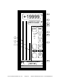
Operator Controls and Front Panel Usage .............. 2
General.................................................................... 2
Front Panel Displays and Pushbuttons ................... 3
RUN Light ............................................................ 3
SP Bargraph ........................................................ 4
OUT Bargraph ...................................................... 4
Numeric Display................................................... 4
Message Display.................................................. 4
DIS Pushbutton.................................................... 4
⇑ and ⇓ Pushbuttons............................................ 5
⇑ and ⇓ Rate of Change ......................................5
AUTO / MAN Pushbutton and Light......................5
Auto/Manual Example...........................................6
ALARM Light.........................................................6
ACK Pushbutton and the Alarm Annunciator........6
User Defined Pushbuttons....................................7
User Defined Lights ..............................................8
Multiple Loops.......................................................8
Section 4:
EDIT Menu Operations
Introduction................................................................ 2
EDIT Keys ................................................................. 3
EDIT Light .............................................................. 3
(ESC) / EDIT key................................................. 3
Edit Value and Scroll Menu Lights ......................... 3
EDIT s and EDIT t keys ..................................... 4
EDIT s and EDIT t Rate of Change ................... 4
ENTER key ............................................................ 4
EDIT Menu Scrolling Example: .............................. 5
EDIT Menus Diagram ................................................ 6
MAIN Menu................................................................ 7
QUICK Menu ............................................................. 7
LAST PARAMETER............................................... 7
SERVICE MANUAL Menu ......................................... 7
What is "Service Manual" (S/M) Mode? ................. 7
RUN light indicates Normal, Forced, or S/M Mode. 8
ENTER S/M (in MAIN Menu)................................. 8
ALL S/M ................................................................. 9
EXIT S/M (in MAIN Menu)..................................... 9
Changing an Output Value in S/M Mode................ 9
PASSWORD Menu.................................................. 10
Password Levels.................................................. 10
Enabling the Password System............................10
ENTER PASSWORD ........................................... 11
SECURE CONTROLLER..................................... 11
TIMEOUT............................................................. 11
CHANGE OPERATOR PASSWORD................... 11
CHANGE TECHNICIAN PASSWORD................. 11
Disabling the Password System........................... 11
EDIT A BLOCK Menu.............................................. 12
General ................................................................ 12
How to use EDIT A BLOCK, an Example............. 13
Softwire the HIALM Block “PV” Input ................... 14
Change the HIALM Setpoint Parameter............... 14
Softwire the PANEL “Alarm Channel 1” Input ...... 14
Entering a “Message” Parameter in PANEL.........15
MEMORY Menu....................................................... 15
AutoLoad.............................................................. 15
Backup Memory Write Protect Jumper................. 15
Backup Memory Socket ....................................... 16
COPY PRIMARY TO BACKUP............................ 16
COPY BACKUP TO PRIMARY............................ 16
ERASE PRIMARY ............................................... 17
COMPARE MEMORIES ...................................... 17
REMAINING MEMORY REPORT ....................... 17
CONFIG. NAME .................................................. 17
EPROM VER. ...................................................... 17
UTILITIES SUB-MENU............................................ 18
EXAMINE ............................................................. 18
EXAMINE Block Outputs ..................................... 18
EXAMINE the Input Signals of a Block ................ 18
FIND FUNCTION ................................................. 18
FIND USAGE....................................................... 19
Forcing Block Outputs.......................................... 19
RUN light indicates Normal, Forced, or S/M Mode
............................................................................. 19
FORCE BLOCK ................................................... 19
UN-FORCE A BLOCK ......................................... 20
UN-FORCE ALL BLOCKS ................................... 20
DISPLAY SCAN TIME ......................................... 20
EDIT QUICK MENU............................................. 20
Entering a Message ............................................. 20
Entering the Block Number.................................. 20
Entering the Parameter Number .......................... 21
BLOCK TIMING................................................... 21
CALIBRATE Menu .................................................. 21
When is Calibration Required? ............................ 21
Analog Inputs Calibration Status Display ............. 22
Analog Input Calibration Procedure ..................... 22
Analog Output Calibration Procedure .................. 23
COM PORT Menu................................................... 24
COM PORT ......................................................... 24
ADDRESS ........................................................... 24
BAUD................................................................... 24
PARITY................................................................ 24
RTU/ASCII ........................................................... 25
+/- DATA.............................................................. 25
TIME OUT............................................................ 25
TEST CABLE....................................................... 25
SUPPORTED MODBUS FUNCTIONS ................ 26
Section 5
Configuring Blockware
Blockware Basics..................................................... 1
Blocks .............................................................. 1
Library of Functions......................................... 1
Any-Function-Any-Block................................. 2
Reusable Functions .......................................... 2
Softwiring......................................................... 2
PCC-III Terminology / Glossary ............................... 5
Block................................................................ 5
Blockware Configuration ................................. 5
Function Type Or Function Code Number....... 5
Input ................................................................. 5
Parameter ......................................................... 6
Analog .............................................................. 6
Discrete ............................................................ 6
ROM ................................................................ 6
RAM ................................................................ 6
EEPROM ......................................................... 6
Retentive Memory............................................ 6
Configuring Blockware Control Logic .......................7
Modifying a “Boiler Master” Blockware Configuration8
Define the requirements....................................8
Check the I/O count ..........................................8
Break the configuration down into manageable
sections .............................................................8
Sketch each section ...........................................9
Change the Function Type of a Block.............10
“Softwire” the Block Inputs ............................10
Configure the front panel displays and alarms 12
Test the configuration .....................................13
Place the controller into operation ..................13
Add Pressure Compensated Steam Flow Blockware
...............................................................................13
Add Purge and Light-off Positioning Blockware .....15
Add Day/Night Pressure Setpoint Blockware .........16
Revised Overall Boiler Master Blockware ..............16
Section 6
Blockware Functions – Technical Reference
Table of Contents, Listed in Function Name Order 2
F0
[A0] Analog Constant, 0.00%
4
F1
[A100] Analog Constant, 100.00%
4
F2
[AIN] Analog Input
4
F5
[RAIN] (RS485) Remote Analog Input
5
F11
[DUAL] Dual Range Flow Transmitter
Selector-Scaler
6
F20
[OPLR] Optical Path Length Ratio
Correlation for Opacity Monitors
7
F22
[BEFF] Boiler Efficiency
7
F31
[HSEL] High Select
9
F32
[LSEL] Low Select
9
F33
[MSEL] Median Selector
9
F34
[ASW] Analog Switch
10
F35
[H/LLIM] High / Low Signal Limiter
10
F36
[RLIM] Rate Limiter
11
F38
[FPT/H] Front Panel Adjustable Track /
Hold
11
F41
[F(T)] Function of Time Generator
13
F42
[F(X)] Function of X Generator with Learn
Mode
15
F43
[L/L] Lead – Lag with Gain ( Dynamic
Compensation )
18
F45
[SCALE] Signal Scaling
19
F51
[AB/C] ( A*B ) / C Multiply - Divide
20
F52
[WSUM] Weighted Sum
21
F53
[INV] Invert
21
F54
[CON] Analog Constant
22
F55
[FPCON] Front Panel Adjustable Constant
22
F56
[DEV] Deviation Calculation (for Bargraph
Displays)
22
F58
[COUNT] Pulse Counter
23
F59
[SQRT] Square Root
24
F60
[ABS] Absolute Value
24
F71
[PID] PID Control ( with GAP and
ADAPTIVE gain)
24
F81
[AOUT] Analog (4-20 mA) Output
28
F83
[TOUT] Triac Output
28
F84
[TCODE] TOUT Fault Code
34
F90
F91
F92
F93
F95
F96
F97
F98
F99
F100
F101
F102
F103
F104
F107
F110
F111
F112
F116
F117
F118
F119
F120
F121
F122
F123
F124
F125
F126
F127
[D0] Discrete 0 Constant
34
[D1] Discrete 1 Constant
34
[DIN] Discrete Input
35
[DCON] Discrete Constant
35
[S/M] Service Manual Status
35
[PANEL] Front Panel Display
36
[RDIN] (RS485) Remote Discrete Input 41
[PB] Pushbutton
42
[LED] LED
43
[TTRIP] TOUT Fault Status
43
[HIALM] High Alarm
44
[LOALM] Low Alarm
45
[DEVALM] Deviation Alarm
46
[RATE] Rate of Change Alarm
47
[LOGIC] User Defined Logic
48
[XOR] Exclusive OR Logic
49
[NOT] NOT Logic
49
[F/F] Flip Flop Logic
50
[TOT] Totalizer (Integrator with Pulse
Output)
50
[DSW] Discrete Switch
51
[DAETDR] Delay After Energize Time Delay
Relay (On Delay)
52
[DADTDR] Delay After De-energize Time
Delay Relay (Off Delay)
52
[INTTDR] Interval Time Delay Relay (NonRetriggerable One Shot)
53
[DAE/DAD] Delay After Energize / Delay
After De-energize Timer
53
[REPTDR] Repeat Time Delay Relay
54
[COMM] RS485 Communications Link
Control
55
[PLINK] Block Parameter Links for
Communications
55
[ROUT] Relay Output
57
[DOUT] Discrete Output (Open Collector Sinking )
58
[NOP] No Operation Dummy Function 58
INTRODUCTION
The PCC-III represents the next generation of digital controllers in that it maintains all of the
advantages of single or multiple loop controllers while addressing many of the features of PLCs and
DCS I/O modules.
The substantially shorter mounting depth (will fit in 8” deep panels); NEMA 13 splashproof front panel;
standard RS-485 communications facility (“Modbus” protocol); and RS-232/laptop as well as front
panel configuration capabilities are certainly readily apparent differences between itself, its
predecessor the PCC-II and its competitors. In addition we have retained and in fact enhanced many
of the features that customers have come to appreciate about our digital controllers … “Service
Manual”; “Learn” function; “Boiler Efficiency” function; “OPLR” Stack Exit Correlation for Opacity
Monitors function (new); Oxygen Sensor Temperature Controller and O2 signal conversion option card
(new) ….
But It is the flexibility of the PCC-III, not simply as measured by its ability to function without its front
panel, but more importantly its I/O expansion capabilities and the significant number of choices
available for expansion that render the PCC-III an unparalleled choice for any control application.
Consider that each PCC-III CPU board has two expansion board slots each of which is able to harbor
any of the available option cards (Note: a third spot is available but is dedicated for use with only one
type of option card). Consider further that there are option cards which can…
•
Control the temperature of Oxygen Sensors and convert their millivolt outputs to signals useful for
control and/or monitoring applications
•
Accept as inputs or output analog signals in per option card combinations ranging from 5AI to
3AI/2AO to 4AO to 2 “Isolated” AI…
•
Accept as inputs or output discrete signals in per option card combinations ranging from 8DI to
4DI/2RO to 4RO …
•
As noted the ability to install the PCC-III CPU board alone (i.e. less front panel) …DCS-III… with
or without any of the combination boards mentioned above further enhancing Data Acquisition and
control capabilities.
So as you read this manual, be sure that you are clear about the vast capabilities of the PCC-III. It is
simply not just another digital controller.
Section 1 – PRODUCT OVERVIEW
Table of Contents
Product Description.....................................................2
Features.........................................................................2
Benefits ..........................................................................2
Distributed Control System Concepts .....................3
Analog and PLC Control Functions ..........................3
Configuration Concepts..............................................3
Com-Link Data Highway Concepts ..........................3
Blockware Concepts ...................................................4
Blocks.....................................................................4
Library of Functions .............................................4
Any-Function-Any-Block.......................................4
Reusable Functions ............................................4
Softwiring...............................................................4
Special Option Card and Special ”Function Block”
Capabilities ...................................................................5
Multiple F(x) ...........................................................5
Learn Mode ...........................................................5
Boiler Efficiency....................................................5
Service Manual (option card) .............................5
Triac Output for Electric Actuators (option
cards) .....................................................................5
Steam Flow Pressure Compensation.............5
PCC III Instruction Manual (rev. 2.3)
Gas Flow Pressure/Temperature
Compensation ..................................................... 5
High Temperature Hot Water (HTHW) BTU/Hr
Computation ......................................................... 6
Drum Level Pressure Vs. Density
Compensation ..................................................... 6
Oxygen Sensor Control/Signal Conversion
(option card).......................................................... 6
Relay Output Channels ...................................... 6
“OPLR” Stack Exit Correlation for EPA Opacity
Monitors ................................................................. 6
Flow Totalization .................................................. 6
PCC III Loop Controller Model Number................... 7
Option Board Input / Output Expansion Examples:7
Spare Parts List ........................................................... 8
PCC-III Specifications ...............................................10
Mechanical:.........................................................10
Environmental:...................................................10
Performance:......................................................10
Operator Control Panel:....................................10
Electrical:.............................................................10
Input/Output (Standard – no option cards):...10
Communications ...............................................10
Page 1-1
Section 1 - Product Overview
Product Description
This section overviews the PCC-III features which address the requirements of both Data Acquisition and control
applications. The PCC-III is designed to address the needs of most process control applications and that
design has been further optimized to meet the exacting needs of combustion control systems.
Features
Benefits
Multiple Loops
Allows cost effective control of more than one
process loop in a single controller.
Service Manual
Allows “Manual” control in the event of
memory, CPU, or digital circuitry failure.
Redundant Memories
Allows for “self recovery” in the event of a
primary memory error.
Optically Isolated Data Highway
Safe/reliable communication that prevents a
single controller failure from disrupting an
entire network. Redundant RS-485
communications are available as an option.
Engineering Units Display Flexibility
Allows the operator to view up to 10 process
variables each with process (tag) descriptions.
Local Blockware Configuration
Allows front panel Blockware configuration
without the need for a special configurator or
laptop computer. Note: a standard RS-232 port
allows laptop configuration as an alternative.
Ten point (“first in-first out”) Alarming
Allows the operator to view the order of alarms
and acknowledge each separately.
“Learn” Function
Allows for easy entry of complex function
curves without prerequisite data collection.
Industry standard communications
Allows the controller to be used in any system
and/or with others hardware/software which
communicate via “Modbus” protocol.
Optional I/O Cards
Allows significant Discrete and Analog I/O
expansion capabilities within a single
controller.
Self-supporting CPU Board
The controller’s CPU board is fully functional
without the front panel, allowing for further I/O
expansion alternatives.
PCC III Instruction Manual (rev. 2.3)
Page 1-2
Section 1 - Product Overview
Distributed Control System Concepts
The PCC-III represents the third generation of process controllers from Preferred Instruments. This controller is
designed to provide a true distributed approach to control applications. The PCC-III provides automation
features that are self sufficient and will operate independently of the remainder of the control system. The PCCIII can be configured as a data collection I/O module (DCS-III) for a data acquisition system, as a multi-loop
controller or as a traditional single loop controller. In all cases the PCC-III will communicate on a network with a
central operator’s station using the industry standard “Modbus” protocol.
Because the PCC-III is self sufficient, control will be maintained even if for any reason, the operator’s station(s)
or network are completely disabled. Further, even if the internal microprocessor or digital electronics of the
PCC-III fail, a “hard manual” option card will allow the process to be manually operated. Lastly, much like a
DCS or PLC I/O card, a complete PCC-III or DCS-III failure affects a relatively small percentage of the overall
system’s I/O. Considering all the above, the need for redundant power supplies, microprocessor cards, or I/O
cards is all but eliminated.
The backbone of the system is the network. The network used between controllers is based upon the industry
standard “Modbus” protocol, using the controller’s integral RS-485 communications facility. This network
communications is optically isolated and can be made redundant (optional).
Analog and PLC Control Functions
The PCC-III includes all the control functions needed for your application. The controller includes not only
traditional analog functions but also many discrete (logical) and timing functions. The controller can handle
many tasks that would normally require the use of a PLC and the use of option cards permits expansion of
those discrete I/O capabilities (up to 13 DI and 10 RO/DO). Discrete functions can also be readily integrated
with analog functions which has been traditionally difficult to accomplish with a PLC due to its purely logical
basis. The combination of integral analog, discrete and timing functions renders the PCC-III a very powerful
control solution.
Configuration Concepts
In most applications the PCC-III is shipped with a factory configuration, but it is designed to permit easy
modification or development of control strategies in the field. The PCC-III can be completely configured using
front panel keys and the digital and alphanumeric displays. The configuration is managed using easy to follow
menus that are controlled by keys on the front panel (Note: these keys are normally locked out with switches
that are located behind the front panel to prevent unauthorized use). The keys allow for field modification or
development of configurations without the use of any other devices such as special configurators or laptop
computers that may not be readily available. An RS-232 port is however available to allow the use of a PC
computer as a configuration tool. The PC also permits the downloading and retrieval of stored configurations
and full documentation of same.
Com-Link Data Highway Concepts
The PCC-III can be networked together over an industry standard “Modbus” network. “Modbus” is an open
architecture format to allow flexibility for future system expansion and/or modification. This network is optically
isolated and makes use of a single pair of wires. The network allows controllers to be located up to 4000 feet
part and up to 31 controllers (plus the “Master”) can be coincidentally networked. The use of “Modbus” as a
communications protocol allows the PCC-III to be integrated with other’s equipment and on networks supplied
by ourselves or others. The “Modbus” communications facility is the industry standard RS-485.
PCC III Instruction Manual (rev. 2.3)
Page 1-3
Section 1 - Product Overview
Blockware Concepts
The PCC-III makes use of “Blockware” which we believe makes control strategy configuration easier. In
Section 5, we will discuss “Blockware” and configuration in greater detail but the basic elements that make up
“Blockware” are as follows:
Blocks
The PCC III memory has 160 Blocks. Each Block is a container that a Blockware Function is put into. Think of a
Block as a “cell” in an Excel or Lotus 1-2-3 spreadsheet, you put a formula or a function into a cell, and the
formula uses the values from other cells as “Inputs” for the formulas. Another analogy would be physical relay
sockets that have signal processing modules plugged into each socket (ie, Block). The controller includes
sufficient memory to handle 160 Blocks.
Library of Functions
The PCC-III has an extensive library of Functions to handle any type of control task. These Functions are
identified and described in detail in Section 6 of this manual. The library includes Functions for the conversion of
Inputs to engineering values, mathematical operations, logical operations, timing operations, the traditional PID
algorithm as well as other types of special PID Functions. Additional special Functions such as “Learn”, “Boiler
Efficiency”, etc. are also included and are described in depth in Section 6.
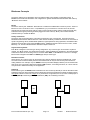
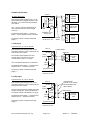
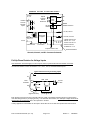
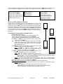
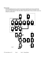
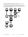
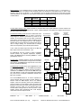
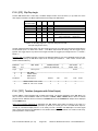
Any-Function-Any-Block
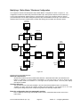
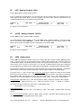
Each Block is assigned a “Function type” during configuration. Any “Function type” can be used in any Block
number. The “Block number” only determines the order in which the Blocks are calculated. In the example below
at left, Block number 22 is not being used, so it has the default NOP, or “No OPeration” Function in it. At Right ,
Block 22 was changed from a NOP to a HIALM (high alarm) Function type.
Reusable Functions
Almost all PCC III “Function types” can be used as many times as required, within the 160 Block limit. There
are some Functions that are directly linked to the hardware that can only be used as many times as there is
mating hardware. For example, only one PANEL Function (Front Panel Display Interface) can be used because
there is only one Front Panel. While those related to PID Functions, curve fitting Functions, etc. can be used as
many times as is deemed necessary for the application.
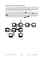
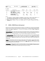
Softwiring
Most Function Types, like HIALM, need information from other sources (ie, Blocks) in order to calculate a result.
Softwiring is the term used to describe how the Blocks are interconnected within the software. Softwiring allows
the Input of a Block to monitor the Output of any other Block. At right below, the PV (Process Variable) Input of
Block 22 (HIALM) is monitoring the Output of Block 20 ( AIN), via a Softwiring connection.
AIN
AIN
NOT
HIALM
20
20
NOP
PV
P
P
V
22
V
22
PID
PID
25
25
PCC III Instruction Manual (rev. 2.3)
Page 1-4
Section 1 - Product Overview
Special Option Card and Special ”Function Block” Capabilities
The following are applications features of the PCC-III which extend its capabilities considerably:
Multiple F(x)
The F(X) “function type” allows for “characterizing” or “curve fitting” of a relationship when that relationship is
non-linear. In combustion control applications, as an example, it is desirable to have the “fuel input” to a burner
follow a linear relation with “firing rate demand”. Even with a properly selected valve trim, the relationship will
not be perfectly linear. But with the application of an F(X) block this objective can be realized. The PCC-III has
the capacity to use as many F(x) functions as are required by the application. In some complex combustion
applications a single controller may use up to 6 to 8 F(x) functions.
Learn Mode
The “Learn Mode” allows for easy commissioning of applications involving single or multiple non-linear
functions. This capability is best described with an example… in combustion control applications, as the firing
rate is increased, the best combustion air damper position will likely not be a linear function. An F(X) block can
be used to effectively linearize the “combustion air flow vs. firing rate” relationship. F(X) blocks will likely be
required for the “fuel valve degree of opening” demand signal and the “Oxygen Setpoint” as well (if O2 Trim is
provided)… The clear benefit of the "Learn Mode” is that at each of the 10 available F(X) Block data points, after
optimum conditions are set by the technician, he/she simply presses the “Learn” button for the PCC-III to
remember (“Learn”) the current firing rate vs. valve and damper positions and “Oxygen Setpoint” relationships
simultaneously. The technician then proceeds in a similar fashion up to full firing rate, repeating this procedure
at each point. This results in a considerable savings in commissioning time, as well as an optimally
“characterized” process.
Boiler Efficiency
The Boiler Efficiency function allows the controller to calculate, in real time, the boiler’s efficiency and display
that result on the controller’s front panel (and/or a recorder or a Data Acquisition terminal). Boiler Efficiency is
calculated using the ASME “by losses” method. This function requires inputs of flue gas temperature,
combustion (ambient) air temperature, percent oxygen in the flue gas, and percent firing rate (for Radiation Loss
determination) to evaluate the efficiency. This function is not only useful for establishing “on-line” fired
equipment efficiency, but as a result allows determination of changes in that efficiency and therefore the
potential for maintenance.
Service Manual (option card)
The optional “Service Manual” feature allows the operator to manually adjust the controller’s output in the event
of a failure of the controller’s microprocessor, power supply, memory or any digital circuitry. In the event of such
a failure, the output will remain at its “last position” until such time as the operator changes that position.
Triac Output for Electric Actuators (option cards)
Many systems utilize electric actuators where a bi-directional “on-off” voltage signal is used to drive the actuator
open or closed. The PCC-III has the optional interface electronics to accomplish this control action.
Additionally the Triac Output option card(s) include “position feedback” input provisions for optimizing control of
actuator position.
Steam Flow Pressure Compensation
Accurate steam flow measurements are very important to the control and monitoring of process systems. Even
though most control systems are designed to assure a constant pressure, variations and/or upsets can occur,
which if unaccounted for, can render records erroneous and produce unacceptable instabilities in all control
loops upon which this measurement depends.
Gas Flow Pressure/Temperature Compensation
Most gas flow measurements require some level of pressure and/or temperature compensation. This becomes
of particular importance when the flow measurement is a significant process control variable as it is in a “fully
metered” combustion control strategy.
High Temperature Hot Water (HTHW) BTU/Hr Computation
An important characteristic of any High Temperature Hot Water Generator is the quantity of BTU’s produced per
interval of time. With inputs of the generator’s inlet and outlet water temperatures and the water’s flow rate this
value can be easily calculated. The resultant figure is typically compared to that from the aforementioned
“Boiler Efficiency” calculation to determine if possible problems have arisen.
PCC III Instruction Manual (rev. 2.3)
Page 1-5
Section 1 - Product Overview
Drum Level Pressure Vs. Density Compensation
In applications where there are large swings in steam demand, the steam generator’s drum level can be
subjected to significant “shrink” and “swell”. Density compensation is an important tool in assuring optimum
drum level control despite these conditions.
Oxygen Sensor Control/Signal Conversion (option card)
Zirconium oxide “in situ” oxygen analyzers include a basic electronics package that maintains sensor
temperatures at exacting levels and as well converts the millivolt output of the sensor into a linear “O2 vs.
milliamp” function (4-20 madc). When equipped with the appropriate option card, the PCC-III performs the
same function as the manufacture’s electronics package, while coincidentally allowing for the automatic
integration of that variable into any planned control or monitoring strategy.
Relay Output Channels
The PCC-III can be equipped with up to 6 Relay Outputs. The Relay contacts are rated for up to 8A inductive
loads and include integral surge suppressors for extended contact life. These outputs can be directly wired into
most burner limit circuits without external “helper” relays.
“OPLR” Stack Exit Correlation for EPA Opacity Monitors
EPA certified stack Opacity monitors are required to display the Opacity as would be viewed at the Stack Exit.
However, the Opacity Transmissometer (ie, the sensor) is never mounted at that location. The PCC-III includes
a “function type” that will calculate the complex EPA mathematical equation to convert (ie correlate) the Opacity
measured at the sensor’s actual location to that at the Stack Exit.
Flow Totalization
The PCC III is equipped with a Pulse Counter “function type” to permit output and subsequent totalization of flow
rates on digital displays. This can eliminate the need for local counters on flow meters in those instances when
they already transmit an analog flow signal to the PCC-III.
PCC III Instruction Manual (rev. 2.3)
Page 1-6
Section 1 - Product Overview
PCC III Loop Controller Model Number
PCC III - a
b
c
0
Option Card Slot Number 1
0 none
5 ch. 4-20 mA / 0-5 Vdc
A AIN
IAIN
3 ch. Isolated 4-20 mA / 0-5 Vdc
B
3 ch. 4-20 mA / 0-5 Vdc
F AIN
AOUT 2 ch. 4-20 mA
Combination Board
G TOUT 2 pair Triac Outputs, 2A 24-120 Vac
AIN
2 ch. Pot / 0-5 Vdc / 4-20 mA
Combination Board
DIN
4
ch.
120
Vac,
Optically-Isolated
J
ROUT 2 ch. Relay Contact, 8 A Inductive
Combination Board
ZrO2
Oxygen
Analyzer
Amplifier
and
Temperature
Controller
Z
R Redundant RS-485 Communications, Optically isolated (Slot 1
only)
Option Card Slot Number 2
Select card type from the “Slot 1” list above
Option Card Slot Number 3
0 none
S TOUT 1 pair Triac Outputs, 2A, 24-120 Vac
Option Board Input / Output Expansion Examples:
PCC III Model Number
PCC-IIIPCC-IIIPCC-IIIPCC-IIIPCC-IIIPCC-IIIPCC-III-
0
A
F
J
G
F
A
0 0
A 0
F 0
J 0
G S
G S
J 0
0
0
0
0
0
0
0
4-20 mA
0-5 Vdc
AIN
5
15
11
5
9
10
10
4-20 mA
AOUT
2
2
6
2
2
4
2
120 Vac
DIN
5
5
5
13
5
5
9
8A
(relay)
ROUT
2
2
2
6
2
2
4
2A
(triac pairs)
TOUT
0
0
0
0
5
3
0
200 mA
(sinking)
DOUT
4
4
4
4
4
4
4
Total
I/O
18
28
28
30
27
28
29
Note: The examples given in no way reflect the number of possible option card possibilities. The PCC-III has a
total of three (3) option card slots, of which one is designated for use by the “S” card only. The remaining two
slots can house any of the remaining option cards in any desired combination. Please refer Section
to
5 to
establish the total 24 VDC power supply requirements, as some combinations may require installation of an
auxiliary power supply
PCC III Instruction Manual (rev. 2.3)
Page 1-7
Section 1 - Product Overview
Preferred Instruments
PCC III Controller
Spare Parts List
Part Number
PCC-III-0000
92227
92233
190315
99595
92204
92223
92076
2759-006A08C
190349
90137
90140
190358
190316
2759-006A03Z
90136
190348
90134
190347
190319
92245
92247
190361
92243
190362
92251
190366
92243
190367
92243
190370
92243
190355
25250-0B253/4MF
Description
Complete PCC III controller, with case & mounting brackets
Main power fuse, 0.3A slo-blo
Ribbon cable assy., door to CPU board
Recommende
d spares per
10 PCC III’s
0.5
2.0
1.0
Available Spare Parts:
CPU board
Backup Memory Module, 8kx8 EEPROM
8 pt. field wiring connector
14 pt. field wiring connector
Slide-on jumper (250 ohm & R/W)
CPU to case retainer screw, 6-32 x 1/2
Front Panel,complete, includes: Bezel, keyboard, display
board, cable, Edit keys door
Front Panel screw with integral O-ring
Front Door gasket
Front Panel with Keybord, less display circuit board
Front Panel display circuit board only
Front Panel display circuit board mounting screws,
6-32 x 3/16
Blank engravable nameplate for Front Panel
Case for panel mounting with rear cover (190347 panel
mounting brackets not included)
Case to panel gasket
Panel Mounting Bracket Kit (2 brackets/kit)
1 pair Triac output option board (slot 3 only)
5 pt. field wiring connector
fuse, 3 A, fast acting
5 ch. 4-20 mA / 0-5 Vdc AIN option board
12 pt. field wiring connector
3 ch. 4-20 mA / 0-5 Vdc isolated AIN option board
6 pt. field wiring connector
3 ch. 4-20 mA / 0-5 Vdc AIN, 2 ch. 4-20 mA AOUT
combination option board
12 pt. field wiring connector
2 ch. 0-5 Vdc / pot AIN, 2 pair 3A 24-120 Vac TOUT (Triac)
combination option board
12 pt. field wiring connector
4 ch. 120 Vac opto-isolated DIN, 2 ch. 8 A ROUT (Relay)
combination option board
12 pt. field wiring connector
PC3_Edit /_Draw RS232 download cable with DB9 adapter
250.0 Ohm Precision Resistor
PCC III Instruction Manual (rev. 2.3)
Page 1-8
Section 1 - Product Overview
PCC-III Specifications
Mechanical:
Case Size:
Enclosure Type:
Front Panel Size:
Panel Cutout:
Weight:
Height: 7.38”; Width: 3.00”; Depth: 7.75”
Flush panel mounted
8.00” H X 3.75” W
7.50” H X 3.13” W (+/-.062)
6 lbs. (excluding option boards)
Environmental:
Operating Temp:
Storage Temp:
Humidity Limits:
Front Panel:
32 to 122oF (0 to 50 oC)
-20 to 150oF (-28 to 65 oC)
15 to 95% (non-condensing)
NEMA 13, IP65
Performance:
Accuracy:
Resolution:
Execution Cycle:
Non-Volitale Memory Life:
0.025% Analog Inputs and Outputs, 70 F
16 bit input / 16 bit output
Ten per second
10.8-30 yrs, Blockware dependent
Operator Control Panel:
Displays:
Alphanumeric:
Numeric:
Bargraph:
Left/Right:
Output:
Pushbuttons:
Faceplate:
Alarm Annunciator:
Status Indicators:
User Defined Pushbuttons:
Electrical:
Input Power Requirements:
Power Supplies:
8 character LED (0.2”)
4.5 digit LED (0.43”)
51 segments LED (5.1”)
20 segment LED (2.1”)
Membrane, tactile feedback
Mylar, splashproof
10 Point, First out
6 LED, Configurable
4, Configurable
120 Vac (+/- 15%), 22 VA
24 Vdc @ 215 mA and 5 Vdc @ 50 mA
Input/Output (Standard – no option cards):
Analog Inputs:
Quantity:
5
Type:
4-20 maDC; 0-5 VDC
Analog Outputs: Quantity:
2
Type:
4-20 maDC, 800 ohm load
Discrete Inputs: Quantity:
5
Type:
120 VAC opto-isolated
Discrete Outputs: Quantity:
6
Type:
(2) SPDT relay contact, 8A, 120V; ½ HP @ 120 VAC
(4) Open Collector (sinking), 24 VDC, 200mA
I/O Expansion:
See Table Below
Communications
Network:
Configuration:
Protocol:
Modbus (ASCII or RTU mode)
Speed: 1200-38,400 baud
Type: RS-485, optically isolated
Speed: 1200-38,400 baud
Type: RS-232 with telephone modular handset connector
Specifications subject to change without notice.
PCC III Instruction Manual (rev. 2.3)
Page 1-9
Section 1 - Product Overview
Section 2:
Installation
Table of contents
Option Board Descriptions ........................................ 1
Mounting Overview.................................................... 2
Mounting Overview.................................................... 2
NEMA 13 / IP65 Environment ................................... 2
Ambient Temperature................................................ 2
Rear Access.............................................................. 2
Mounting ................................................................... 2
PCC III Dimensions ............................................... 3
Panel Cutout Dimensions ...................................... 3
Wiring Overview ........................................................ 4
120 Vac Ground .................................................... 4
Terminal Blocks..................................................... 4
Wire Type.............................................................. 4
Shielded Cable ...................................................... 4
24 Vdc & 5 Vdc Power Supply Load Calculations .... 5
Fuses ........................................................................ 5
250 ohm Resistors for 4-20 mA Inputs ...................... 5
“A” Option Board 250 ohm Switches ..................... 6
CPU Board Layout ................................................ 7
“F” Option Board 250 ohm Switches ..................... 8
“G” Option Board Fuses and Pull-ups ................... 8
“J” Option Board Isolated Neutral Jumpers ........... 9
“S” Option Board 120 Vac Fuse ............................ 9
CPU Board Field Wiring Terminals.......................... 10
Option Board Field Wiring Terminals.......................10
Option Board Field Wiring Terminals.......................11
Two Wire 4-20 mA Input, Internal 24 Vdc...........12
Two Wire 4-20 mA Input, External 24 Vdc..........12
Four Wire 4-20 mA Input .....................................12
Isolated 4-20 mA Input ........................................13
1-5 Vdc Input .......................................................13
0-10 Vdc Input .....................................................13
Potentiometer Input .............................................14
Potentiometer Input, “G” Board ..........................14
4-20 mA Output ...................................................14
120 Vac Discrete Inputs, CPU Board ..................15
120 Vac Discrete Inputs, “J” Board......................15
Relay Output .......................................................16
Discrete Output, Sinking, Internal 24 Vdc...........16
Discrete Output, Sinking, External 24 Vdc..........16
Triac Output, Other AC Loads ............................17
DC Commons and AC Neutrals Isolation ................17
DC Commons and AC Neutrals Isolation ................18
Pull-Up/Down Resistor for Voltage Inputs................19
RS485 Communications Wiring...............................20
RS232 Blockware Download Cable .........................22
Field Installation of Option Boards...........................23
Installing Front Panel Legends ................................24
Option Board Descriptions
Option Board Slot 1 or Slot 2
AIN
5 ch. 4-20 mA / 0-5 Vdc
A
IAIN
3 ch. Isolated 4-20 mA / 0-5 Vdc
B
AIN
3 ch. 4-20 mA / 0-5 Vdc
F
AOUT 2 ch. 4-20 mA
Combination Board
TOUT 2 pair
Triac Outputs, 2A 24-120 Vac
G
AIN
2 ch. Pot / 0-5 Vdc / 4-20 mA
Combination Board
DIN
4 ch. 120 Vac, Optically-Isolated
J
ROUT 2 ch. Relay Contact, 8 A Inductive
Combination Board
AIN
3 ch. mV, Optically-Isolated
ZP Oxygen Analyzer
Z
TOUT 1 ch. Triac Outputs, 2A, 120 Vac
Combination Board
Note: The 'Z' Option Board is described in the ZP Oxygen Analyzer Manual, it is NOT covered by this Manual.
Option Board Slot 3
TOUT 1 pair
Triac Outputs, 2A, 24-120 Vac
S
PCC III Instruction Manual (rev. 2.3)
Page 2-1
Section 2 - Installation
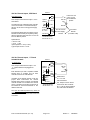
Mounting Overview
PCC III is designed for flush mounting in an enclosure in a NEMA 13 (IP65) indoor environment. Continuous
operation is guaranteed over the 32-125 F (0-52 C) ambient temperature range without derating. The controller
should not be subjected to excessive vibration. The PCC-III is UL508 recognized for NEMA 1 dry indoor
applications. The NEMA 13 rating is based on Preferred Instruments testing and is not third party UL508
recognized.
NEMA 13 / IP65 Environment
A NEMA 13 environment is generally defined as: Intended for indoor use primarily to provide a degree of
protection against dust, and splashed or sprayed water, oil, or non-corrosive coolant. NEMA 13 is generally
equivalent to the European IEC standard IP65.
The PCC III front panel and case gasketing will provide NEMA 13 protection if the enclosure to which the PCC III
is mounted itself is designed for NEMA 13 (minimum) protection.
PCC III can be installed in more severe environments if the user provides additional protection that is consistent
with and/or required for the area’s rating.
Ambient Temperature
PCC III is rated for continuous operation over the 32-125 F (0-52 C) ambient temperature range without derating.
A typical PCC III installation (in a control cabinet mounted next to an industrial packaged boiler) would not require
cabinet cooling. However, each installation should be evaluated individually to determine if the PCC III ambient
temperature (ie, the control cabinet internal temperature) will exceed 125 F.
The control cabinet internal temperature is a function of the outside air temperature, the surface area of the
control cabinet, and the amount of heat released by other components inside the cabinet. A PCC III consumes
22 VA worst case, therefore, it releases a maximum of 75 Btu/hr. The major control cabinet manufacturers
(Hoffman, Hammond, …) include information in their catalogs to help calculate cabinet internal temperature rise
(with and without various cooling methods).
Rear Access
The PCC III case is 7 ¾ “ deep behind the mounting flange; therefore, PCC III can be mounted in 8” or deeper
control cabinets. All field wiring connections are located behind a cover plate in the rear of the controller. Rear
access is required for installation, calibration, and trouble shooting. Routine operation and control strategy
Blockware downloading is accomplished from the front of the controller.
Mounting
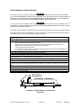
Refer to the PCC III Mounting and Panel Cutout Dimension drawings that follow. Cut the hole in the enclosure.
Remove any burrs and loose metal chips. Remove the Panel Mounting Brackets from the PCC III case. Slide the
PCC III into the hole. From the rear of the PCC III, slide the Mounting Brackets tabs into the slots in the PCC III
case. Using a 1/8” Allen wrench, tighten each mounting bracket screw against the enclosure.
Additional Mounting Brackets can be ordered as part number 190347, if the mounting brackets supplied with the
PCC III are lost or damaged.
PCC III Instruction Manual (rev. 2.3)
Page 2-2
Section 2 - Installation
Flange
Gasket
3/4" conduit K.O.
1/8" hex socket
Gasket
.5
.75
.88
.5 max
8
7.38
Removable
Rear Cover
3/4" Conduit K.O.
1/2" Conduit K.O.
3.75
1.13
Field Wiring
Terminal
Blocks
Located
1.13
7.75
3
PCC III Dimensions
(inches)
1.75"
.63 min
7.50
min
3.13
Panel Cutout Dimensions
and Minimum Spacings (inches)
PCC III Instruction Manual (rev. 2.3)
Page 2-3
Section 2 - Installation
Wiring Overview
WARNING
The PCC-III is commonly used to control potentially dangerous Combustion and Chemical Processes. VERIFY
THAT THE PROCESS BEING CONTROLLED HAS BEEN SAFELY SECURED, ISOLATED, OR BYPASSED (AS
REQUIRED BY THE SITE CONDITIONS) BEFORE REMOVING POWER FROM THE PCC-III CONTROLLER.
FAILURE TO DO SO CAN RESULT IN EQUIPMENT DAMAGE, INJURY, OR DEATH.
WARNING
It is very common to have multiple sources of power among the wires connected to a PCC-III. VERIFY THAT ALL
SOURCES OF POWER HAVE BEEN DISCONNECTED BEFORE WORKING ON WIRING. FAILURE TO DO SO
CAN RESULT IN INJURY OR DEATH.
All Panel and Field wiring should conform to National and Local Electrical Codes. Typically, NEC (National Electric
Code) applies to field wiring; while NFPA 79 and UL508 applies to Industrial Control Panel wiring.
120 Vac Ground
Connect the incoming AC Power Ground (ie “Green Wire” Ground) to the screw and lug marked “GROUND”
inside the rear of the case near the bottom of the terminal strips. AC Ground is not connected to DC Common.
See “DC Commons and AC Neutrals” on page 2-18.
Terminal Blocks
!
(See Field Wiring Label on pg. 2-10)
All Field Wiring terminals are separable, and plug-in to the PC board. This allows rapid board level replacement
without disconnecting individual field wires. Verify that Terminals are inserted properly before applying power.
The AC terminals on the CPU board are numbered 1L to 8L and 1U to 8U. The terminals are arranged in two rows
of eight. “L” refers to the Lower row, while “U” refers to the Upper row.
Terminals 1L to 8L, 1U to 8U, and 29 to 33 accept 24 – 12 ga. wire and should be tightened to 4.5 in-lb.
Terminals 1 to 28, and 40 to 51 accept 22 – 14 ga. wire and should be tightened to 2.2 in-lb.
Wire Type
All wiring (AC, DC, and shielded cable) should be copper, stranded, 150 V min., and 60° C minimum.
Shielded Cable
All 4-20 mA / 0-5 Vdc Input and Output wiring should be 22 gauge minimum, 85% shield (min.), and have twisted
pairs (Belden 8737 or equal). 100% foil shielding is preferable if available.
The shields of all 4-20 mA / 0-5 Vdc cables should be connected at one end only, as shown on the drawings that
follow. Generally, the shield is connected to the DC common of the Power Supply that is powering the signal. All
shield foils, and shield wires should be insulated (taped or heat shrink) to prevent accidental connection to earth or
power ground. Shields connected at both ends, or unintentional second grounds can actually add extra noise to a
signal instead of reducing noise. To prevent noise pick-up, shielded cables should never be run in conduits or
trays with AC wiring (any voltage). Ignition transformer and variable frequency drive AC wiring is particularly noisy
and should be kept separated from all DC signal wiring.
PCC III Instruction Manual (rev. 2.3)
Page 2-4
Section 2 - Installation
24 Vdc & 5 Vdc Power Supply Load Calculations
The PCC III CPU board has a built-in 24 Vdc power supply that is rated for 215 mA continuous output at 138 Vac
and 125 F. The 215 mA current limit is based on the sum of all 24 Vdc loads; CPU board, Option boards, and field
(terminals 10, 16, 27, 28). Below is a worksheet to calculate total 24 Vdc current load.
Item
mA
Qty.
Total
each
2 wire 4-20 mA xmtrs
20
that are powered by PCC III
4-20 mA Outputs
20
(CPU + “F” board(s) )
Relays
25
(CPU + “J” board(s) )
“B” Isolated Input board(s)
55
“G” Triac Board, 24V powers +5Vdc
50 max
Field wiring load dependent
Total mA Load:
Notes:
1) Only count 4-20 mA Outputs and Relays that are actually being used.
2) Each “B” board draws 55 mA regardless of how many Input channels are being used.
3) Example: a PCC-III-BF00 that is configured to use three 4-20 mA Outputs and
1 Relay Output draws 155 mA internally. Therefore, 60 mA is available for field loads (typically
transmitters).
4) A direct short across the 24 Vdc will blow the PCC III 120 Vac power fuse. An external 300 mA fast-acting
fuse for field +24 Vdc loads is recommended.
5) The CPU has a 5 Vdc / 50 mA power supply for field devives (feedback pots, etc.). Each “G” option board also
has a separate 5 Vdc / 50 mA power supply. Note the “G” board 5Vdc current usage subtracts from the
available 24 Vdc current.
Fuses
Every PC board in the PCC III that uses a fuse is shipped with one spare fuse attached to the PC board
(see drawings on pages 2-7 thru 2-9 for fuse locations). Fuses used in the PCC III include:
Board
Service
Amps
Type
Preferred
Littlefuse
Part Number Part Number
CPU
120 Vac power to
0.3 A
Slo-Blo
92227
239.300
+5 and +24 Vdc supplies
250 V, 5x20 mm
“G” and “S” Triac 24-120 Vac power to Triacs
3.0 A
Normal Blow
92247
235.003
option boards
250 V, 5x20 mm
250 ohm Resistors for 4-20 mA Inputs
Except for the “G” Option Board, every PCC III Analog Input channel has an internal 250.0 ohm precision resistor
that the user can connect to the Input. If connected, the 250 ohm resistor converts a 4-20 mA signal into a 1-5
Vdc signal.
The CPU Board utilizes jumpers that slide onto header pins to connect the 250 ohm resistors to the Inputs. The
“A”, “B”, and “F” Option Boards have DIP switches. See the drawings on pages 2-6 through 2-9 for the locations of
the 250 ohm resistor switches and jumpers.
The “G” Option Board is used primarily to drive electric actuators with position feedback potentiometers. The “G”
Option Board does not have internal 250 ohm resistors for the two Analog input channels on this board. Externally
mounted 250 ohm resistors are required if these Analog Inputs are connected to 4-20 mA signals. Precision
250.0 ohm resistors are available separately as part number 25250-0B25-3/4.
PCC III Instruction Manual (rev. 2.3)
Page 2-5
Section 2 - Installation
AIN ch. 5
AIN ch. 1
To Connect 250 ohm Resistor:
Turn Switch ON
“A” Option Board 250 ohm Switches
4-20 mA / 0-5Vdc Analog Inputs, 5 Channels
AIN ch. 1
AIN ch. 3
To Connect 250 ohm Resistor:
Turn Switch ON
Rev. 0: “B” Option Board, 250 ohm Switches
4-20 mA / 0-5Vdc Isolated Analog Inputs, 3 Channels
(Isolated Ch. to Ch. and from CPU Signal Common)
AIN ch.3
AIN ch.1
To Connect 250 ohm Resistor:
Turn Switch ON
Rev. A: “B” Option Board, 250 ohm Switches
4-20 mA / 0-5Vdc Isolated Analog Inputs, 3 Channels
(Isolated Ch. to Ch. and from CPU Signal Common)
PCC III Instruction Manual (rev. 2.3)
Page 2-6
Section 2 - Installation
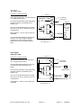
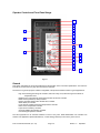
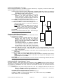
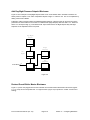
CPU Board Layout
Shown with 3 Option Boards Installed
CPU Board
120 Vac Fuse
Option Board 3
Terminals
CPU Board
Terminals 1U – 8U
CPU Board
Terminals 1L – 8L
RS232 Blockware
Download Port
Option Board 1
Terminals
Backup Memory Write
Protect Jumper
CPU Board
Terminals 1 - 28
Front Panel Cable
Connector
Option Board 2
Terminals
Backup Memory
Socket
CPU Board 250 ohm
jumpers, AI1-AI5
CPU Board-to-Case
Retainer Screw
Option Board 250
ohm Switches
PCC III Instruction Manual (rev. 2.3)
Page 2-7
Section 2 - Installation
AIN ch. 1
AIN ch. 3
To Connect 250 ohm Resistor:
Turn Switch ON
“F” Option Board 250 ohm Switches
Combination: 4-20 mA / 0-5Vdc Analog Inputs, 3 Channels
4-20 mA Analog Outputs, 2 Channels
Fuse for Pair 1 (Term. 42 & 43)
Fuse for Pair 2 (Term. 45 & 46)
AIN ch. 2
AIN ch. 1
330k Pull-Up Resistor:
Remove if External Pull-Down Resistor
or External 250 ohm Resistor is in use.
“G” Option Board Fuses and Pull-ups
Combination: 0-5Vdc Analog Input, 2 Channels
Triac Output (AC Solid State Switch), 2 Pairs (4 Triacs)
PCC III Instruction Manual (rev. 2.3)
Page 2-8
Section 2 - Installation
DIN ch. 4 Neutral
DIN ch. 1 Neutral
Neutrals are Isolated ch. to ch.,
Neutrals of Selected Channels can be
Connected by Installing Jumpers.
“J” Option Board Isolated Neutral Jumpers
Combination: 120 Vac Isolated Discrete Inputs, 4 Channels
Relay Outputs, 8A, ½ HP, 2 Channels
Fuse for Pair 1 (Term. 30 & 31)
“S” Option Board 120 Vac Fuse
Triac Output (AC Solid State Switch), 1 Pairs (2 Triacs)
PCC III Instruction Manual (rev. 2.3)
Page 2-9
Section 2 - Installation
CPU Board Field Wiring Terminals
Preferred Instruments, Danbury CT
PCC III Field Wiring
120
Vac
tie
points
N 1L
L 2L
L 3L
DIN 1 4L
DIN 2 5L
120
Vac
DIN 3 6L
DIN 4 7L
label 90133
Option Boards not shown for clarity
DIN 5 8L
PCC III Instruction Manual (rev. 2.3)
1
2
3
4
5
6
7
8
9
10
11
12
13
14
15
16
17
18
19
20
21
22
23
24
25
26
27
28
1
JP2
5
1U N
2U L
120 Vac
22 VA
50/60 Hz
3U NC
4U C
5U NO
6U NC
7U C
ROUT 1
120 Vac
8A max
!
ROUT 2
8U NO
+
COM
DOUT +
DOUT 1
DOUT 2
DOUT 3
DOUT 4
DOUT + 24 V
AOUT 1 +
AOUT 1 AOUT 2 +
AOUT 2 +5V
+ 24 V
AIN 1 +
AIN 2 +
AIN 3 +
AIN 4 +
AIN 5 +
+ 24 V
+ 24 V
ISOLATED
RS 485
24 Vdc
200 mA
SINKING
4-20 mA
800 ohms
50 mA max
0-5 Vdc
or
4-20 mA
JP2 jumpers
connect
250 ohm
resistors
180 mA max
AIN 250 ohm
resistor jumpers
Page 2-10
Section 2 - Installation
Option Board Field Wiring Terminals
PCC III Option Board
Field Wiring Terminal Numbers
(for Option Board Slots 1 or 2)
Model:
40
A
Analog Input
+
B
Isolated Analog Input
40
+
AI x-1
41
-
42
+
-
44
+
41
-
42
+
-
46
+
+
43
-
44
+
41
-
42
+
-
J
Discrete Input 120 Vac
Relay Output
40 HT
TRIAC HOT
40 R1
41 NT
NEUTRAL
41 R1
42 I1
42 R2
43 D1
INC 1
TO x-1 (pair 1)
DEC 1.
43 R2
44 NT
NEUTRAL
44 H1
45 I2
45 N1
RO x-1
AI x-2
43
-
44
+
IAI x-3
45
G
Analog Input
Triac Output
AI x-1
IAI x-2
AI x-3
45
40
IAI x-1
AI x-2
43
F
Analog Input
Analog Output
RO x-2
AI x-3
DI x-1
45
-
46
-
SC
46 D2
INC 2
TO x-2 (pair 2)
DEC 2.
47
-
SC
47 NT
NEUTRAL
47 N2
48
+
46 H2
AI x-4
47
-
48
+
DI x-2
49
-
50
-
SC
51
-
SC
48
+
+ 5 Vdc
48 H3
49
+
AI x-1
49 N3
50
+
AI x-2
50 H4
51
-
SC
51 N4
AO x-1
AI x-5
49
-
50
+
51
-
DI x-3
AO x-1
Notes:
DI x-4
PCC III "S" Option Board
Field Wiring Terminal Numbers
(Option Board Slot 3 Only)
Any Combination of the above Option Cards can be used in
Slots 1 or 2
"x" indicates the PC Board Number in the above channel descriptors
0 = CPU board, 1 = Option Slot 1, 2 = Option Slot 2
29 HT
TRIAC HOT
30 I1
INC 1
TO x-1 (pair 1)
31 D1
DEC 1.
All of the above Option Cards use the same Terminal Numbers
When wiring schematics are created, label Terminals as "x - term. no."
"x" is the option card slot number. Examples:
1-46 means Option Card 1, terminal number 46
2-46 means Option Card 2, terminal number 46
PCC III Instruction Manual (rev. 2.3)
Page 2-11
32 NT
NEUTRAL
(Tie Point)
33 NT
NEUTRAL
Section 2 - Installation
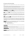
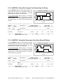
Wiring Examples
Two Wire 4-20 mA Input,
Internal 24 Vdc
Typical for: CPU, “A”, and “F” boards.
This example shows Analog Input 1 on the
CPU Board. Install JP 2-1 to connect the
internal 250.0 ohm resistor.
The shield connects to the PCC-III Signal
Common “-“.
PCC III
+ 24 Vdc 16
1-5 Vdc
to A/D
+
+ 17
JP2-1
Jumper
250.0
ohms
-
4-20 mA Two
Wire Xmtr
Insulate Shield
18
SC
(Signal Common)
Terminals shown
are for: AI ch. 0-1
Two Wire 4-20 mA Input,
External 24 Vdc
Typical for: CPU, “A”, and “F” boards.
This example shows Analog Input 2 on the
CPU Board. Install JP 2-2 to connect the
internal 250.0 ohm resistor.
The External Power Supply “-“ and the PCC III
Signal Common “-“ must be connected.
The shield connects to the External Power
Supply “-“.
PCC III
+ 24 Vdc 16
1-5 Vdc
to A/D
Insulate Shield
+ 19
-
JP2-2
Jumper
+
250.0
ohms
4-20 mA Two
Wire Xmtr
20
+
SC
(Signal Common)
-
24 Vdc
Power
Supply
Terminals shown
are for: AI ch. 0-2
Four Wire 4-20 mA Input
Typical for: CPU, “A”, and “F” boards.
This example shows Analog Input 3 on the
CPU Board. Install JP 2-3 to connect the
internal 250.0 ohm resistor.
PCC III
+ 24 Vdc 16
1-5 Vdc
to A/D
The Transmitter “-“ and the PCC III Signal
Common “-“ must be connected.
The shield connects to the Transmitter “-“.
+
JP2-3
Jumper
-
250.0
ohms
PS
-
Terminals shown
are for: AI ch. 0-3
Page 2-12
4-20 mA
Four Wire
Xmtr
22
SC
(Signal Common)
PCC III Instruction Manual (rev. 2.3)
Insulate Shield
+ 21
PS
120 Vac or 24 Vdc
Xmtr Power Input
Section 2 - Installation
Isolated 4-20 mA Input
PCC III
“B” Option Board Only.
The External Power Supply “-“ and the “B
Board “-“ for this channel must be connected.
The shield connects to the External Power
Supply “-“.
4-20 mA
Indicator
+
Isolator
This example shows Analog Input 2 on a “B”
Option Board that is plugged into Slot 2. Turn
ON switch 1-2 to connect the internal 250.0
ohm resistor.
The “-“ of each channel is isolated from all
other channels and from the CPU Signal
Common “-“.
-
+
2-42
+
SW1-2
250.0
-
-
2-43
to A/D
+
4-20 mA Two
Wire Xmtr
Isolated ch. to ch.
and from SC
+
Terminals shown
are for: AI ch. 2-2
Insulate
Shield
-
24 Vdc
Power
Supply
1-5 Vdc Input
Typical for: CPU, “A”, and “F” boards.
This example shows Analog Input 4 on the
CPU Board. Remove JP 2-4 to disconnect the
internal 250.0 ohm resistor.
The 5 Mohms input impedance of each
channel allows over 15 PCC-IIIs to be
connected to the same 1-5 V signal.
See “Pull-Up/Down Resistors” in this Section
The External Power Supply “-“ and the PCC III
Signal Common “-“ must be connected.
The shield connects to the External Power
Supply “-“.
PCC III
Insulate Shield
+ 24 Vdc 28
1-5 Vdc
to A/D
250.0 ohm
+ 23
+
JP2-4
Jumper
-
250.0
ohms
4-20 mA
Four Wire
Xmtr
or PCC III
24
SC
(Signal Common)
Terminals shown
are for: AI ch. 0-4
0-10 Vdc Input
Typical for: CPU, “A”, and “F” boards.
PCC III
This example shows Analog Input 5 on the
CPU Board. Remove JP 2-5 to disconnect the
internal 250.0 ohm resistor.
The two external precision resistors reduce the
signal by exactly 50%. Set the AIN Block for a
0-5V range, instead of the default 1-5V range.
The External Power Supply “-“ and the PCC III
Signal Common “-“ must be connected.
The shield connects to the External Power
Supply “-“.
+ 24 Vdc 27
0-5 Vdc
to A/D
+ 25
JP2-5
Jumper
250.0
ohms
Voltage Divider.
Two 10k, 0.1% resistors,
P/N 25100-2B50-1/4F
(Not Included)
Insulate Shield
+
26
-
0-10 Vdc
Four Wire
Xmtr
SC
(Signal Common)
Terminals shown
are for: AI ch. 0-5
PCC III Instruction Manual (rev. 2.3)
Page 2-13
Section 2 - Installation
Potentiometer Input
PCC III
Typical for: CPU, “A”, and “F” boards.
+ 5 Vdc
This example shows Analog Input 1 on the
CPU Board. Remove JP 2-4 to disconnect
the internal 250.0 ohm resistor.
The +5 Vdc power supply (term. 15) is rated
at 50 mA.
The shield connects to the Signal
Common “-“.
Note: For Actuator Feedback Pots
See “Pull-Up/Down Resistors” in Section 2,
and F83 TOUT in Section 6 for Fault Mode
wiring considerations
0-5 Vdc
to A/D
15
+
17
R1
JP2-1
Jumper
250.0
ohms
R2
18
SC
(Signal Common)
Terminals shown
are for: AI ch. 0-1
Potentiometer Input,
“G” Board
“G” Option Board Only.
1-48
+ 5 Vdc
The +5 Vdc power supply (term. 1-48) is
rated at 50 mA, total. If two pots are
connected to the +5 Vdc, then the smallest
value is 200 ohms (each).
The “G” board has a built-in pull-up resistor.
It must be removed if an external 250.0 ohm
resistor is required.
Note: R1, R2 are optional external
resistors. See "Pull-Up/Down
Resistors" in this section for details.
Note: Internal Pull-Up only
included on "G" Option Board.
PCC III
This example shows Analog Input 1 on a “G”
Option Board that is plugged into Slot 1.
There are no 250.0 ohm resistors on the “G”
board.
Potentiometer
100 ohms min.
10k ohms max.
Wiper
330 k
+
1-49
0-5 Vdc
to A/D
Potentiometer
100 ohms min.
10k ohms max.
Wiper
1-51
SC
(Signal Common)
Terminals shown
are for: AI ch. 1-1
The shield connects to the Signal
Common “-“.
4-20 mA Output
Typical for: CPU, and “F” boards.
Insulate Shields
PCC III
+24 V
+
This example shows Analog Output 1 on the
CPU Board.
-
The maximum 4-20 mA total loop resistance
external to the PCC III is 800 ohms.
+
11
12
The shield connects to the Signal
Common “-“.
SC
(Signal Common)
Terminals shown
are for: AO ch. 0-1
PCC III Instruction Manual (rev. 2.3)
Page 2-14
+
-
4-20 mA
I/P
4-20 mA
I/P
Total Loop:
800 ohms max.
Section 2 - Installation
120 Vac Discrete Inputs, CPU Board
PCC III
CPU Board Only.
This example shows Discrete Input 1 on the
CPU Board.
Field "Hot" and
PCC III "Hot"
can be different
120 Vac
phases.
Hot
4L
Optical
Isolator
.33 uF
AC
The Neutral for the 5 Discrete Input channels
on the CPU board is connected internally to
the PCC III 120 Vac incoming power supply
Neutral.
Provided that all Discrete Input power source
Neutrals are Grounded (as required by NEC),
then the Discrete Inputs and PCC III “Hot” can
be from different phases.
120
Neutrals
from DI ch.
0-2 -> 0-5
Neutral
1L
1U
to PS xfmr
PCC III 120 Vac
Power Supply
Neutral
Grounded
Neutral
(Per NEC Code)
Terminals shown
are for: DI ch. 0-1
Specifications:
> 90 Vac = ON
< 3 mA = OFF
Input Impedance = 8 k (+/- 20%)
Typical Input Current = 15 mA
120 Vac Discrete Inputs, “J” Board
Isolated Neutrals
PCC III
“J” Board Only.
This example shows Discrete Input 1 on a
“J” Option Board that is plugged into
Slot 1.
1-44
Optical
Isolator
.33 uF
120 Vac
Hot
120
Neutral
AC
Each Discrete Input has a separate isolated
Neutral which is isolated from all other
channels and from the CPU Neutral.
If Isolation is not desired, jumpers on the JP1
jumper block interconnect the channel
Neutrals. Each jumper connects an individual
channel Neutral to an isolated inter-channel
tie bus. Therefore two jumpers would have to
be installed to connect the Neutrals of two
different channels.
H1
1-45
ch. 2
ch. 3
ch. 4
Terminals shown
are for: DI ch. 1-1
N1
Isolated from
ch.<->ch. and
CPU AC Neutral
JP1 Jumpers can be used to
interconnect "Nx" Terminals.
N1 <-> N4 are always isolated
from CPU board AC Neutral.
The CPU AC Neutral (terminal 1U) does not
connect to the “J” board. An external wire must
be run if the these isolated Neutrals need to be
connected.
PCC III Instruction Manual (rev. 2.3)
Page 2-15
Section 2 - Installation
PCC III
Relay Output
NO
Typical for: CPU, and “J” boards.
8U
This example shows Relay Output 1 on the
CPU Board.
The Relay contacts are protected from
damage due to inductive loads by a capacitor
and a 150 V Varistor. To prevent damaging
the Varistor, do not apply voltages greater
than 145 Vac across the Relay contacts.
When the Relay Contacts are Open, less
than 1.8 mA of leakage current is applied to
the load through the snubber cap and
Varistor.
6U
Terminals shown are
for: ROUT ch. 0-2
Discrete Output, Sinking,
Internal 24 Vdc
Note:
"J" Option Boards
do not have NC
Terminals
Relay Coil
+24 V
This example shows Discrete Output 1 on
the CPU Board.
Coil loads (relays, solenoids, …) require
an additional field mounted clamp diode
on the actual coil to prevent noise
induction in adjacent field wiring.
NOTE: Incorrect clamp diode Polarity
causes a direct short.
NC
PCC III
CPU Board Only.
DOUT channels are Open Collector
Transistors (ie “Sinking”) with internal
clamping diodes. When active, the DOUT
conducts DC current to Power Common.
120 Vac max.
8A Inductive
1/2 HP, 120 Vac
C
7U
Surge
Clamp
Diodes
to
DOUT
ch. 2-4
10
4
+
5
Insulate
Shield
9
PC
(Power Common)
Terminals shown are
for: DOUT ch. 0-1
Mount Clamp Diode on Coil
to Prevent Electrical Noise
NOTE POLARITY!!
Each DOUT channel is rated 200 mA max.
load. See “24 Vdc Power Supply” on page 2-5
to calculate the mA current available from the
24 Vdc Power Supply.
The shield connects to the Power
Common “-“.
PCC III
Discrete Output, Sinking,
External 24 Vdc
The same comments noted above apply.
This example shows an External Power
supply being used to power the load.
The shield connects to the External
Power Supply “-“.
10
Clamp Diodes
4
ch. 0-2
ch. 0-3
ch. 0-4
5
+
CPU Board Only.
+24 V
+
-
PC
(Power Common)
Page 2-16
Relay
Coil
9
Terminals shown are
for: DOUT ch. 0-1
PCC III Instruction Manual (rev. 2.3)
0-36 Vdc
Power
Supply
Insulate
Shield
-
Mount Clamp Diode on Coil
to Prevent Electrical Noise
NOTE POLARITY!!
Section 2 - Installation
Triac Output,
Reversible Actuator
Typical for: “G” and “S” boards.
This example shows Pair 1 of a Triac Output on
a “G” Option Board in Slot 2.
PCC III
3A Fuses F1
to second
F2
pair
The Triacs are protected by surge suppressing
capacitors, inductors, and varistors (6 mA
leakage, typ).
2-40
H 24-120 Vac
Power Input
N
Actuator
2-41
2-42
Increase
The Triac Hot and Neutral supply are isolated
from the PCC III 120 Vac. Each Triac pair has
a separate fuse.
Max. Load
2 Amps
(FLA)
Motors rated 24 – 120 Vac, and 0-2 Amps are
acceptable.
2-43
The “G” Board also includes two Analog Input
channels. If a Position Feedback signal is
required by the control strategy, See the
potentiometer and 4-20 mA input examples
above.
2-44
Decrease
Neutral
Terminals shown are
for: TOUT ch. 2-1
Triac Output,
Other AC Loads
PCC III
Typical for: “G” and “S” boards.
3A Fuse
F1
This example shows Pair 1 of a Triac Output
on a “S” Option Board in Slot 3.
The TOUT Blockware allows each Triac to be
controlled as a separate Solid State AC
Switch.
29
H
33
N
30
24-120 Vac
Power Input
T1 (Increase)
Solenoid Valve
The Triacs are protected by surge suppressing
capacitors, inductors, and varistors (6 mA
leakage, typ).
31
The Triac Hot and Neutral supply are isolated
from the PCC III 120 Vac. Each Triac pair has
a separate fuse.
Loads rated 24 – 120 Vac, and 0-2 Amps are
acceptable.
PCC III Instruction Manual (rev. 2.3)
T2 (Decrease)
Horn
32
Neutral
Terminals shown are
for: TOUT ch. 3-1
Page 2-17
Section 2 - Installation
DC Commons and AC Neutrals Isolation
The drawing on page 2-19 shows the relationships between the various “Grounds” and “Commons” within the
PCC III.
A thorough understanding of these relationships will prevent unintended “Ground Loops” in the DC and AC field
wiring. “Ground Loops” is a general term to describe unintended current flows via AC Ground or DC Common
circuits, which generally are NOT drawn on a schematic as a distinct field wiring connection.
DC Ground Loops can cause lower than expected 4-20 mA values due to a portion of the current bypassing the
intended circuit path and traveling through some unintended parallel path. AC “Ground Loops” can cause Ground
Fault Interrupter Circuit Breakers to trip if current returns via a “Neutral” that is not protected by the GFCI breaker.
Green Wire Ground: The incoming AC power Ground (the “Green” wire) is only connected to Case Ground (ie, the
metal enclosure). Case Ground is isolated from all Neutrals and all DC Commons. Case Ground should always be
connected to the appropriate power supply Ground, per NEC.
Line: The CPU AC Power “Line” Input (Terminal 2U) is internally connected to CPU terminals 2L and 3L. CPU
Terminal 2U is NOT internally connected to any of the option boards. If a connection is desired, external wiring is
required.
Hot: The “Hot” Power Inputs to the “G” and “S” Triac Output Option Boards are isolated from the CPU “Line” Input.
Each Option Board “Hot” is Isolated from the “Hot” of the other Option Boards. If a connection is desired, external
wiring is required. The “Hot” Input for a particular Triac Option Board is a common input that feeds all Triacs on
that board.
Neutral: The CPU AC Power “Neutral” Input (Terminal 1U) is internally connected to CPU terminal 1L. CPU
Terminal 1U is NOT internally connected to any of the option boards. If a connection is desired, run a field wire
from the CPU board to the Option Board.
CPU Terminal 1U is the return path (or Neutral) for all current that enters any of the CPU 120 Vac Discrete Input
channels (Terminals 4L – 8L). The “Hots” and “Neutral’” of all “J” Option Board 120 Vac Discrete Input channels
are isolated from the CPU Board “Line” and “Neutral”. Each “J” Board Input channel is isolated from each other
“J” board channel. The “J” Board is provided with jumpers to allow connecting the Neutrals of the channels
together if desired.
DC Common: The DC commons ( “-“) are isolated from case ground. All Signal Commons on the CPU board are
interconnected, and are also connected to the Signal Commons on the “A”, “F”, and “G” Option Boards.
Specifically, the following terminals are all internally connected to each other:
CPU:
9, 12, 14, 18, 20, 22, 24, 26
“A”:
x-41, x-43, x-45, x-47, x-49, x-51
“F”:
x-41, x-43, x-45, x-46, x-47, x-49, x-51
“G”:
x-51
Power Common (PC): Terminal 9 on the CPU Board is reserved for “noisy” electrical loads such as external relay
coils, and solenoids.
Signal Common (SC): Except for Terminal 9 (Power Common), all other DC Commons are referred to as Signal
Common, and should be connected to low noise 0-5 Vdc and 4-20 mA circuits.
Isolated Signal Commons: The “-“ terminal of each channel of a “B” Option Board is isolated from all other
channels on that Option Board and from the CPU Board. The “+” terminals are also isolated channel to channel
and from the CPU.
Isolated RS485: Terminal 3 (“COM”) is the isolated DC Common of the isolated power supply that powers the field
wiring portion of the Isolated RS485 Communications Link. The RS485 Data “+” and “-“ (terminals 1 & 2) are also
isolated from the CPU Board.
PCC III Instruction Manual (rev. 2.3)
Page 2-18
Section 2 - Installation
CPU Board AC to DC, and DC to DC Isolation
To DIN
ch 1-3
Isolated
120 Vac
Discrete
Inputs
Optical
Isolators
to/from
Serial Port
7L
D+
RS485
Xmtr
Rcvr
+
1
D2
3
DC-DC
Isolator
8L
15
1U, 1L
DC Power
Supplies
Fuse
10, 16, 27, 28
2U, 2L, 3L
Ground
Case Ground
12, 14, 18, 20
22, 24, 26
No
Connection
9
RS485
Isolated Common
+ 5 Vdc, 50 mA
+ 24 Vdc, 215 mA
- Signal Common for:
AIN ch. 0-1 -> 0-5
AOUT ch 0-1 & 0-2
- Power Common
for DOUT ch 1->4
to Option Cards 1 & 2
Terminal Numbers
Grounds, Neutrals, and DC Commons Schematic
Pull-Up/Down Resistor for Voltage Inputs
This Sub-Section does NOT apply to 4-20 mA Inputs; that is, Inputs with the 250 ohm Resistor connected.
The 250 ohm resistor is never connected for: 1-5 V, 0-5 V, 0-10 V, and Potentiometer Inputs.
Typical Internal Circuitry for Analog Inputs
+
15
+ 5 Vdc
R1
+ xx
Field
Terminals
150k 150k
JP2-x
Jumper
R2
-
250.0
0-5 Vdc
to A/D
.68 uF
typ. 2
xx
SC
(Signal Common)
0.6 Hz Filter
(-63 db @ 60 Hz)
Each Analog Input has a low pass noise filter with high quality, low leakage capacitors for 60 Hz noise rejection.
If the field wiring breaks, a pot wiper gets dirty, or is otherwise disconnected, the A/D Input Voltage will remain at
the last value for several hours due to the capacitors in the filter.
In many applications it is desirable for the Input to fail to either 0V or 5V after the Input becomes disconnected.
PCC III Instruction Manual (rev. 2.3)
Page 2-19
Section 2 - Installation
A Pull-Up Resistor (R1) will force the Input to 5V after a wire break.
A Pull-Down Resistor (R2) will force the Input to 0V after a wire break.
If Required, install only one (1) Resistor, either R1 or R2. Do NOT install BOTH resistors.
The value of R1 or R2 depends on the impedance of the field device, the desired response time, and the
acceptable level of error introduced by the resistor. Each application should be analyzed separately.
Example: An Input for a 1k Position Feedback Pot on an electric actuator with an “R1” Pull-Up Resistor equal to
330k. This combination adds less than 0.05% error, and has a 3 sec. response time. If the pot is wired such that
approx. +5 V is 100% Open, then TOUT will drive the actuator fully closed if the feedback pot wiper circuit
becomes disconnected. If the desired effect is to make the actuator fail open, then reverse the +5 and Common
wires to the pot, and re-calibrate TOUT.
The CPU, “A”, “B”, and “F” boards do not include pull-up or pull-down resistors. If desired, the user must mount
them externally.
The “G” option board includes an integral 330k Pull-Up Resistor on each Input channel.
RS485 Communications Wiring
RS-485 communications wiring (terminals 1-3) is optically isolated and is not electrically connected to any other
circuits within the PCC III. This means that an accidental short to the RS485 cable will not affect the operation of
the other controllers (up to 31 units) connected to the cable.
RS-485 cabling may be up to 4000 feet in length. Longer distances can be accommodated by using RS-485
repeaters. RS-485 Network cabling should always be arranged in a “bus”. Do not wire cabling in a “star” or with
“stub” connections. See Drawings below for examples of “bus” and “stub” wiring layouts.
Belden P/N 3106A (Preferred part number 16284) is the recommended shielded cable for all PCC III RS-485
communications data highways. Belden 3106A is specifically designed for RS485 applications, and is 3 wire
shielded cable arranged as: 1 twisted pair with a foil shield, plus a separate single insulated conductor that is not
twisted into the main pair. The 3 wires are surrounded by a second braided shield and an overall PVC insulation.
Belden 3106A has a characteristic impedance of 120 ohms, has 22 Ga. conductors, and is rated 300V @ 60C.
Shielding and RS-485 Commons: The shield should be connected to the RS-485 common terminal at the master
station. At each PCC, PLC, RS-485/232 converter and any other devices on the network, the shields should NOT
be connected to each controller’s RS-485 common. The shields of the network cables should be wired together so
as to continue the shield to the next controller. The single wire (ie, not part of the twisted pair) in the cable should
be connected to all the Communications DC Commons on the RS-485 network. Cut off the foil and braided
shields, insulate the bare shield wire and any exposed shield and connect as shown below.
RS232/RS485 Converters: Typical DCS and SCADA workstations have RS232 communications ports, and
require an external RS232/RS485 converter. RS232/RS485 converters are available from: Telebyte Technology
(516-423-3232) Model 8324. The RS485 Cable must have exactly one set of Pull-Up/Pull-Down resistors installed
to insure that the cable is biased to greater than 0.2 Vdc differential in the “Idle” state (ie, no nodes are
transmitting). The Model 8324 has internal Pull-Up/Pull-Down resistors that are activated by setting DIP switches.
PCC III Instruction Manual (rev. 2.3)
Page 2-20
Section 2 - Installation
ORG
WHT
1
2
3
ORG
1
2
3
BLU
PCC III
WHT
BLU
Belden 3106A
no substitutes
PCC III
ORG
1
2
3
D+
D-
WHT
BLU
COM
PCC III
4000 ft. cable length max.
(Use Repeaters if greater than 4000 ft)
Daisy Chained Bus Layout: OK
PCC III
PCC III PCC III
PCC III
PCC III PCC III
PCC III
ScadaFlex
Workstation
PCC III PCC III
PCC III
ScadaFlex
Workstation
Daisy Chained Bus Layout: OK
PCC III
PCC III PCC III
PCC III
Daisy Chained Bus Layout: OK
PCC III PCC III PCC III
ScadaFlex
Workstation
PCC III PCC III
PCC III
Bus with Stubs Layout: Not Acceptable
PCC III
PCC III PCC III
PCC III
PCC III PCC III
PCC III
ScadaFlex
Workstation
PCC III
PCC III PCC III
PCC III
ScadaFlex
Workstation
Star Layout: Not Acceptable
PCC III
PCC III PCC III
PCC III Instruction Manual (rev. 2.3)
Page 2-21
Section 2 - Installation
RS232 Blockware Download Cable
The PCC-III is capable of uploading and downloading Blockware Configurations and other diagnostic information
via the RS-232 port on the CPU board. The signals are standard RS232 levels and can be directly connected to a
standard Personal Computer Serial Port. The RS232 Port DC Common pin is connected to the PCC III Power
and Signal Commons.
The connector on the CPU board is a standard 4 pin telephone handset modular jack. The wiring to connect a
PCC III to a Personal Computer is shown below.
A pre-fabricated Download Cable with 4 pin modular to 9 pin DB-9 RS232 connector adapter is available as
Preferred part number 190355. Assembly 190355 is also included with each PC3_Edit and PC3_Draw software
package.
+5
Download
sense bit
Tx
Rx
1
1
2
2
3
3
3
2
4
4
5
PCC III
RS232
Download
Connector
Standard Telephone Handset
coiled cord with modular
connectors
PCC III
Download
Adapter
(p/n 190355)
Tx
Rx
Personal
Computer
9 pin male
serial port
connector
1 4
Front View
Download Connector
Pin-out
PCC III Instruction Manual (rev. 2.3)
Page 2-22
Section 2 - Installation
Field Installation of Option Boards
WARNING
The PCC-III is commonly used to control potentially dangerous Combustion and Chemical Processes. VERIFY
THAT THE PROCESS BEING CONTROLLED HAS BEEN SAFELY SECURED, ISOLATED, OR BYPASSED (AS
REQUIRED BY THE SITE CONDITIONS) BEFORE REMOVING POWER FROM THE PCC-III CONTROLLER.
FAILURE TO DO SO CAN RESULT IN EQUIPMENT DAMAGE, INJURY, OR DEATH.
WARNING
It is very common to have multiple sources of power among the wires connected to a PCC-III. VERIFY THAT ALL
SOURCES OF POWER HAVE BEEN DISCONNECTED BEFORE WORKING ON WIRING. FAILURE TO DO SO
CAN RESULT IN INJURY OR DEATH.
The quantity of PCC III Input and Output channels can be expanded by adding up to three plug-in Option Boards.
These Option Boards can be field installed by competent Instrument Technicians. Refer to the procedure below,
the Drawing below, and the CPU Board Layout drawing on page 2-7.
If the PCC-III is controlling a process, it must be safely taken out of the control loop before attempting to
install any option cards.
Remove all power to the instrument. Multiple Power Sources may be present.
Remove the Front Panel From the PCC III:
Remove the screw on the top of the Front Panel.
Grasp the top corners of the Front Panel and move it forward, away from the case, about ½”.
Move the Front Panel Upwards and away from the case about ½”.
The Front Panel should now be free.
Depress the two retainer clips on each side of the ribbon cable connector on the CPU Board, and
remove the Ribbon Cable Connector.
Remove the rear cover from the PCC III.
Note where each field wiring Terminal Strip Connector is plugged-in.
Unplug the field wiring Terminal Strip Connectors at the rear of the circuit boards.
Unscrew the “Board-to-Case” Retainer Screw (see CPU Layout, pg. 2-7). It is located in the lower rear area
of the CPU Board, next to the JP2 250 ohm jumper header .
Prepare a static free work area and protect all circuit boards from a static discharge.
Slide the main PCB out of the PCC III and place on a static protected mat.
Install the option cards as shown below. Note that the Connector for Option Slot 2 will have pins that
purposely do not plug into the Option Board, plug-in as shown. Option Slots 1 and 3 do not have any “extra”
pins.
Reassemble the instrument in reverse order.
Calibration may be required, see Section 4, “CALIBRATE Menu”.
Wire the new Option Board(s).
Re-assemble in the reverse order.
Plug-in Field
Wiring
Option Board
CPU Board
Installation of Option Boards onto CPU Board
(Side View)
PCC III Instruction Manual (rev. 2.3)
Page 2-23
Section 2 - Installation
Installing Front Panel Legends
Power –down the PCC-III Controller.
WARNING: un-plugging or plugging in the front panel ribbon cable with power on can damage the
controller or cause it to re-boot and possibly upset the controller process in a Dangerous manner.
Remove the front door of the PCC-II, and un-plug the ribbon cable from the door to the CPU.
Lay the door face down on a table to view the back of the front door.
Un-plug the clear plastic ribbon cable from the keypad to the display board.
Remove the three screws that secure the display board, and remove the display board.
The Legend insert slides into the keyboard pocket that is located just to the left of the short red bargraph window.
Re-assemble the Front door, and plug-in all cables.
Apply Power to the PCC-III.
Note: Legends are typically made by creating a MS Word or MS Excel document, and then printing the legend on
an 8 ½ x 11 piece clear plastic. The legend is then cut down to the 2.1” H x 1.75” W pocket size. Contact
Preferred Instruments Service department for a free MS Excel file that is a pre-formatted template for PCC-III
Legend Inserts.
PCC III Instruction Manual (rev. 2.3)
Page 2-24
Section 2 - Installation
Section 3
Operation
Table of Contents
Operator Controls and Front Panel Usage ...............2
General ....................................................................2
Front Panel Displays and Pushbuttons.....................3
RUN Light .............................................................3
SP Bargraph .........................................................3
OUT Bargraph ......................................................4
Numeric Display....................................................4
Message Display ..................................................4
DIS Pushbutton.....................................................4
⇑ and ⇓ Pushbuttons ............................................5
PCC III Instruction Manual (rev. 2.3)
⇑ and ⇓ Rate of Change ...................................... 5
AUTO / MAN Pushbutton and Light...................... 5
Auto/Manual Example .......................................... 5
ALARM Light ........................................................ 6
ACK Pushbutton and the Alarm Annunciator........ 6
User Defined Pushbuttons.................................... 7
User Defined Lights .............................................. 7
Multiple Loops ...................................................... 8
Page 3-1
Section 3 - Operation
Operator Controls and Front Panel Usage
22
4
23
5
1
6
7
2
8
10
11
9
12
14
3
13
20
19
15
21
18
16
17
22
Figure 1
General
This section will explain the Front Panel displays and the operation of the Front Panel pushbuttons. This section is
intended as an aid to the every day user of the PCC III controller.
The PCC III is a general purpose, software configurable, microprocessor based controller. Typical applications:
High school heating plant firing rate controller, with time of day clock, start time logic and outside air
temperature reset
Multiple burner, high pressure steam boiler fuel flow and air flow controller
Boiler furnace pressure (ie draft) controller
Electric generator steam turbine throttle valve controller
Waste water pH controller
Pump and Fan variable speed drive flow/pressure controller
Batch reactor temperature controller
Paper stock consistency controller
Chemical additive ratio blending controller
Heat treating temperature controller
The same physical PCC III controller hardware is used in every case. What differentiates one controller from
another is the application-specific Blockware (ie, control strategy software) in the memory of the PCC III.
PCC III Instruction Manual (rev. 2.3)
Page 3-2
Section 3 - Operation
By design the PCC III is exceedingly flexible, and very adaptable. For convenience, this section will use specific
examples to explain how to operate the PCC III. However, the reader should remember that each PCC III will be
programmed differently to suit the needs of a particular application. For this reason, one must consult the
documentation for the Blockware loaded in the memory of your specific PCC, and become familiar with
your particular installation before attempting to operate the PCC III controller.
In particular, the operation of the 4 pushbuttons and 6 lights (items 12 – 21) shown in Figure 1 changes depending
on the Blockware (ie, Control Logic) that has been loaded into the memory of the PCC III. Throughout this
Section, the words: “Typically”, “Optionally”, “Configurable”, and “User defined” will be used to indicate that the
operation of a pushbutton or display may in fact vary from that described in the examples given in this section.
Front Panel Displays and Pushbuttons
RUN Light
Item 9 in fig.1: The green RUN light indicates the health of the hardware, and indicates if the Blockware is being
over-ridden (ie, FORCED or S/M), or has errors (S/M).
The RUN light should be ON continuously.
If the RUN light is Blinking or it is OFF, the PCC III Blockware is not operating properly. A Technician
should be called immediately to determine the cause of the problem. It is normal for a Technician to
purposely put the PCC III into either S/M or FORCE mode during various maintenance procedures. However, the
PCC III should not be in S/M or FORCE mode during normal operation. See Section 4 for details on S/M and
FORCE modes.
The RUN light indicates Normal, Forced, or S/M Mode
Green RUN Light ON / OFF Cycle
Operating Mode
ON
OFF
ON
OFF
Continuous
Normal
95%
Blinks OFF once every second
Forced Block(s)
(see Section 4)
ON
Blinks ON twice every second
OFF
85%
Service Manual
ON
OFF
Continuous
Not Operating
Note: S/M Mode RUN light indication takes priority over FORCED Mode
indication when both S/M and FORCED Modes are active.
PV Bargraph
Item 1 in fig.1: Typically, bargraph provides a graphical display of the Process Variable (PV) over a range of from
0-100%. “Process Variable” is control system slang for: “that specific system condition that the PCC III is trying to
control”.
Put another way, if the PCC III is modulating a steam valve in order to control the burner fuel oil temperature, then
the oil temperature is the PV (that is, Process Variable). If the PCC III is a boiler feedwater controller, the boiler
drum water level is the PV.
However, the Blockware Designer is free to use this bargraph to display any other variable. The bargraph has 50
segments (individual lights), plus one “zero” light; therefore, each segment represents 2% of the range of the
signal being displayed.
SP Bargraph
Item 2 in fig.1: Typically, this bargraph provides a graphical display of the Setpoint (SP) over a range of from 0100%. “Setpoint” is control system slang for: “that specific value at which the PCC III should maintain the Process
Variable”.
PCC III Instruction Manual (rev. 2.3)
Page 3-3
Section 3 - Operation
Put another way, if the PCC III is modulating a steam valve in order to control the burner fuel oil temperature, then
as noted above the oil temperature is the PV (that is, Process Variable). If you want to keep the oil temperature at
a constant 220 deg F, then the Setpoint would be 220 deg F.
Typically, when the two bargraphs are setup to display PV and SP simultaneously, both bargraphs will be at the
same height when the PCC III is in AUTO and the controller is maintaining the desired Setpoint.
However, the Blockware Designer is free to use this bargraph to display any other variable. The bargraph has 50
segments (individual lights), plus one “zero” light; therefore, each segment represents 2% of the range of the
signal being displayed.
OUT Bargraph
Item 3 in fig.1: Typically, this bargraph provides a graphical display of the OUTput of the PCC III over a range of
from 0-100%. “Output” is control system slang for: “whatever the PCC III is changing in an effort to maintain the
process at the desired setpoint”.
Put another way, if the PCC III is modulating a steam valve in order to control the burner fuel oil temperature, then
the 4-20 mA signal being sent to the steam valve positioner is the Output. In this case the OUT bargraph would
indicate 0-100% of the steam control valve’s opening demand signal.
However, the Blockware Designer is free to use this bargraph to display any other variable. The bargraph has 20
segments (individual lights), plus one “zero” light; therefore, each segment represents 5% of the range of the
signal being displayed.
Numeric Display
Item 4 in fig.1: This display is used to show numbers. Typically the values shown are shown in the correct
engineering units. That is, the numbers are usually not in units of from 0-100%. See ACK and DIS for more
details.
Message Display
Item 5 in fig.1: This display is used to show messages that can be displayed using the characters A-Z, 0-9, and
most of the recognized symbols (+, -, <, /, %, ….). The message display can show up to 8 fixed characters at a
time or longer messages which simply scroll across the display. See ACK and DIS for more details.
All of the Process Display channel messages, and all of the Alarm Annunciator messages can be modified by the
user in the field without any special programming hardware (see section 4).
DIS Pushbutton
Item 7 in fig.1: The PCC-III is capable of displaying up to 10 channels of Process Control information. Pressing
the DIS pushbutton causes the next display channel to appear on the Message and Numeric displays. The display
channel sequence repeats after the last channel is displayed. Repeatedly pressing the DIS pushbutton in order to
cycle through the display channels is called “scrolling” through the display channels.
Each display “channel” consists of a Numeric display and a Message display working as a matched pair to display
one “variable”. Pressing DIS to scroll through the display channels causes both the Numeric and Message
displays to change to the next display channel at the same time.
A typical display “channel” example would be boiler drum steam pressure (the “variable”). After scrolling to this
display channel with the DIS pushbutton, the Numeric display (item 4) might show “+ 149” (for 149 psig) while the
Message display (item 5) simultaneously showed “DRUM PSI”.
If the displays are currently showing an Alarm Annunciator message, press DIS to return to the display of the
Process Control display channels.
The operation of the DIS pushbutton can not be changed by the Blockware designer. In normal operation, the DIS
pushbutton can always be used to scroll through the display channels.
There are only three reasons why depressing the DIS pushbutton would not cause a change in the display
channel:
If the EDIT light (item 22) is ON. See Section 4 for instructions on how to exit the EDIT mode.
The Blockware loaded in the PCC III memory does not have any display channels.
PCC III Instruction Manual (rev. 2.3)
Page 3-4
Section 3 - Operation
If the green RUN light is OFF or blinking indicating that the controller may need to be serviced.
⇑ and ⇓ Pushbuttons
Item 10 and 11 in fig.1: These pushbuttons are used to increase or decrease the value that is currently being
displayed on the Numeric display. These pushbuttons can only be used to change values that the Blockware
Designer has configured to be modifiable from the Front Panel.
Typically the Setpoint, the Controller Output (when in Manual), Ratio, Bias, and other values can be changed with
these pushbuttons.
The Blockware Designer can also limit the amount of adjustment that is possible. For example, if The Setpoint is
normally 150 psig, the Blockware designer can internally limit the range of adjustment to 125 – 175 psig.
⇑ and ⇓ Rate of Change
When the Operator presses and holds down either the ⇑ or ⇓ pushbutton, the displayed value will initially ramp
slowly. However, after every 10 counts the display ramp speed increases by a factor of ten. Therefore, the longer
the ⇑ or ⇓ pushbutton is pressed, the faster the displayed value will change.
Example:
Assume the Numeric display initially shows 0.00
The Operator presses and continuously holds down the ⇑ pushbutton.
The Numeric display would change as follows:
0.00, 0.01, 0.02, 0.03, 0.04, 0.05, 0.06, 0.07, 0.08, 0.09,
0.10, 0.20, 0.30, 0.40, 0.50, 0.60, 0.70, 0.80, 0.90,
1.00, 2.00, 3.00, 4.00, 5.00, 6.00, 7.00, 8.00, 9.00
…
Note: the ramping sequence does not have to start with the right hand digit equaling “0” as shown in the above
example. If the initial display value had been 0.03, the ramp rate would change after 0.13, 1.03, 10.03, 100.03, …,
that is after every 10 display value changes.
Whenever the ⇑ or ⇓ pushbutton is released, the ramping rate is reset to the slowest rate. Therefore, if you
don’t want the displayed value to change rapidly, release the ⇑ or ⇓ pushbutton after the displayed value
has changed by 8 or 9 counts.
AUTO / MAN Pushbutton and Light
Items 14 and 15 in fig.1: This pushbutton and light are both User defined.
However, it would be very unusual for a Blockware designer to use this pushbutton / light pair for
anything besides selecting the Automatic or Manual mode for the controller’s Output.
Typically, when the light is ON, the controller is in Manual (MAN). When the light is OFF, the controller is in
Automatic (AUTO). The pushbutton is typically configured as a toggle type. That is, every time the pushbutton is
pressed, the status toggles to the opposite status: MAN to AUTO, AUTO to MAN, MAN to AUTO, ….
Auto-DIS (Automatic Display Channel Selection): Auto-DIS is an optional feature that most Blockware designers
utilize. Auto-DIS connects the AUTO/MAN pushbutton to the display channel selection logic as follows:
When AUTO / MAN changes from MANual to AUTO, display ch. 2 (typically the PV) is automatically selected.
When AUTO / MAN changes from AUTO to MANual, display ch. 1 (typically the OUT) is automatically selected.
However, after Auto-DIS has changed the display channel, the Operator can still use DIS to select a different
display channel.
Without Auto-DIS, the Operator would have to first change the AUTO / MAN pushbutton and then manually
change the display channel with the DIS pushbutton.
Auto/Manual Example
This example would cover a typical Blockware control logic case. However, your Blockware may be different.
Review the documentation provided with the Blockware for your specific controller to determine the purpose of
each pushbutton.
PCC III Instruction Manual (rev. 2.3)
Page 3-5
Section 3 - Operation
Assume that the controller has the AUTO/MAN pushbutton configured to allow selection of either the automatic or
manual mode … Auto-DIS is in use … there is NO Blockware that overrides MAN mode … the Output is currently
in AUTO … and the Output is initially set to 4%.
To put the controller Output into Manual and then set the Output (ie, the valve, or damper, or …) to 20 % open:
Press the AUTO / MAN pushbutton.
The AUTO / MAN light will come ON, indicating that the Output is in Manual mode.
The Display channel will automatically change to the Output channel (VALVE, or DAMPER, or a similar
message will be displayed on the Message display).
Press and hold the ⇑ pushbutton.
The Numeric display will start ramping up from 4%.
Momentarily release, and then press and hold the ⇑ pushbutton when the Numeric display shows
12 or 13.
This resets the ramp rate change logic, and keeps the ramp rate at the slowest ramp rate.
When the Numeric display shows 20, release the ⇑ pushbutton.
If desired, you can now press the DIS pushbutton to scroll through (ie, change) the display channels.
As long as the AUTO / MAN pushbutton remains in Manual (the light will be ON), the Output will remain
at 20%, even though a different display channel may be displayed.
If an alarm occurs, you can press the ACK button to view the alarm message, and to silence the alarm
horn (if supplied). The Output will remain at 20%. Press DIS to return to the display channels.
No matter which display channel is currently being displayed, when the AUTO / MAN button is pressed
again, the Output will return to that corresponding with the Automatic control mode.
ALARM Light
Item 8 in fig.1: The Alarm Light operates as follows:
Alarm
Light
Blinking
ON
OFF
Status
One or more alarm messages have NOT been displayed.
Press ACK to display the next alarm message.
All alarm messages have been displayed.
1 or more alarm inputs are still in the alarm condition.
All alarm messages have been displayed.
No alarm inputs are in the alarm condition.
The operation of the ALARM light can not be changed by the Blockware designer. However, alarm(s) can be
disabled by Blockware. Typically, this is done to prevent nuisance alarms when a process is shutdown.
ACK Pushbutton and the Alarm Annunciator
Item 6 in fig.1: The PCC-III can monitor up to 10 different alarm conditions. This pushbutton is used to
ACKnowledge new alarms, and typically to silence an optional panel-mounted or remote alarm horn or bell.
When a new alarm condition occurs, the ALARM light (item 8) will start blinking. Optionally, the Blockware
designer can cause the PV and SP bargraphs to blink, and if supplied, activate a panel-mounted or remote alarm
horn, bell, and/or light.
Pressing ACK will cause the Message display to show the first of up to 10 alarm messages, and it will silence any
optional alarm horns or bells. If the ALARM light continues to blink, then there are additional alarm messages that
have not been displayed. Press ACK again to allow the next alarm message to appear on the Message display.
The Annunciator records and plays back alarm messages in the same sequence as the alarms actually occurred.
The Numeric display is used to indicate the sequence number of the alarm message currently being displayed,
and the total quantity of alarm messages in the alarm memory. The Numeric display shows two numbers
separated by a blank space. The left digit is the sequence number (1 is the first to occur) and the right digit is the
total quantity of alarm messages in memory. Alarms that are no longer in the alarm state are deleted from the list
after all message have been displayed at least once.
Example:
A feedwater controller monitors and has alarm channels for: Low Feedwater Supply Pressure, High Drum Level,
Low Drum Level, and Low-Low Drum Level. Assume that a boiler modulates up to maximum rate, but the
PCC III Instruction Manual (rev. 2.3)
Page 3-6
Section 3 - Operation
feedwater pump capacity is inadequate, the feedwater pressure drops, the drum level drops and the boiler
eventually trips due to low-low water level. After the boiler trips the feedwater pressure returns to normal pressure.
The displays would respond as follows:
Condition
Low feedwater
supply pressure
Low Drum Level
Low Low Drum
Level trip
Feedwater Supply
Pressure returns to
normal
ALARM
light
Blink
Blink
Blink
Blink
Blink
Blink
Blink
Low Low Level trip
returns to normal
ON
ON
Low Level returns
to normal
OFF
OFF
OFF
Message
Numeric
ACK
pushbutton
Process Control
Display
Process Control
Display
Process Control
Display
Process Control
Display
Process Control
Display
Process Control
Display
Process Control
Display
Process Control
Display
LOW WATER PSI
LOW DRUM
LEVEL
LO-LO DRUM
LEVEL
LOW DRUM
LEVEL
LO-LO DRUM
LEVEL
LO-LO DRUM
LEVEL
NO MORE
ALARMS
Process Control
Display
1
2
3
3
Press
Press
3
3
Press
1
2
Press
2
2
Press
2
2
Comment
Operator not present
Operator returns
Press
Process Control
Display
Press DIS
pushbutton
When one wishes the displays to stop showing Alarm Annunciator messages, and return to showing normal
Process Control display channels, press DIS (Item 7).
The operation of the ACK pushbutton can not be changed by the Blockware designer. However, alarm(s) can be
disabled by Blockware. Typically, this is done to prevent nuisance alarms when a process is shutdown.
User Defined Pushbuttons
Items 12, 14, 16, and 18 in fig.1: These four pushbuttons are configured by the Blockware designer. The Purpose
and Operation of each of these pushbuttons is determined by the Blockware designer. Review the documentation
provided with the Blockware for your specific controller to determine the purpose of each pushbutton.
Items 12 and 16 can be labeled by the user to indicate the purpose of each pushbutton. Items 14 and 18 are
permanently labeled.
User Defined Lights
Items 13, 15, 17, 19, 20 and 21 in fig.1: These six lights are configured by the Blockware designer. The Purpose
and Operation of each of these lights is determined by the Blockware designer. Review the documentation
provided with your specific controller’s Blockware to determine the purpose of each light.
Items 13, 17, 20, and 21 can be labeled by the user to indicate the purpose of each light. Items 15 and 19 are
permanently labeled.
The four lights that are located within the outline of a pushbutton are all actually controlled by Blockware that is
independent of the operation of the pushbutton itself. While it is very common for these four lights to be used to
indicate when the pushbutton is ON, it is not unusual for some of these lights to be used as simple indicators that
are not affected by the operation of the mating pushbutton.
PCC III Instruction Manual (rev. 2.3)
Page 3-7
Section 3 - Operation
Multiple Loops
PCC III can control more than one “loop” at the same time. The method used to accomplish this is selected by the
Blockware Designer. Review the documentation provided with your specific controller’s Blockware to determine
the requirements specific to your application. Two different loop select methods are described below. Only one of
the two methods will be used.
LOOP Pushbutton Loop Select Method: As shown in figure 1, one PCC III can simultaneously control Boiler Firing
rate based on Drum pressure (the first “loop”) and the Feedwater Control Valve based on Drum Level and Steam
Flow (the second “loop”). However, the Front Panel displays will display only one of the two loops at a time. The
Operator will Select which loop is to be displayed by pressing the LOOP pushbutton.
In this example, the PSI and LEVEL lights indicate which loop (LEVEL or PSI) is currently being displayed on the
bargraphs, and which loop Auto-DIS is using to select a display channel (see pg. 3-5 for Auto-DIS). Pressing the
LOOP pushbutton causes the selected loop to toggle back and forth: LEVEL to PSI, PSI to LEVEL, LEVEL to
PSI,…
Once a loop is selected, Auto-DIS works as described above for the currently selected loop. If PSI is the selected
loop: Auto-DIS would display PSI when the PSI AUTO/MAN button is put into AUTO, and FIRING RATE when put
into MAN. If LEVEL was the currently selected loop, Auto-DIS displays DRUM LEVEL in AUTO and
FEEDWATER VALVE in MAN.
AUTO/MAN Pushbuttons Loop Select Method: An Alternative method for selecting the currently displayed loop is
to use one of the two AUTO/MAN pushbuttons for each loop as the as the loop select Pushbutton. This method is
used when there is no Loop pushbutton.
If the LEVEL loop is currently being displayed, pressing the PSI AUTO/MAN pushbutton would change the
displays from the LEVEL loop to the PSI loop, but the PSI AUTO/MAN status would not change. After the PSI loop
has been selected for display, pressing the PSI loop AUTO/MAN pushbutton would toggle the Auto-Manual status
as expected.
One of the two lights, PSI or LEVEL (items 20 and 21) would be ON to indicate which loop is being displayed.
When the PSI loop is currently being displayed, pressing the LEVEL AUTO/MAN pushbutton would change the
displays from the PSI loop to the LEVEL loop, but the LEVEL AUTO/MAN status would not change. After the
LEVEL loop has been selected for display, pressing the LEVEL loop AUTO/MAN pushbutton would toggle the
Auto-Manual status as expected.
PCC III Instruction Manual (rev. 2.3)
Page 3-8
Section 3 - Operation
Section 4:
EDIT Menu Operations
Table of Contents
Introduction ............................................................... 2
EDIT Keys ................................................................. 3
EDIT Light.............................................................. 3
(ESC) / EDIT key ................................................ 3
Edit Value and Scroll Menu Lights ......................... 3
EDIT ▲ and EDIT ▼ keys .................................... 4
EDIT ▲ and EDIT ▼ Rate of Change................... 4
ENTER key............................................................ 4
EDIT Menu Scrolling Example: .............................. 5
EDIT Menus Diagram................................................ 6
MAIN Menu ............................................................... 7
QUICK Menu............................................................. 7
LAST PARAMETER .............................................. 7
SERVICE MANUAL Menu......................................... 7
What is "Service Manual" (S/M) Mode?................. 7
RUN light indicates Normal, Forced, or S/M Mode 8
ENTER S/M (in MAIN Menu) ................................ 8
ALL S/M................................................................. 9
EXIT S/M (in MAIN Menu) .................................... 9
Changing an Output Value in S/M Mode ............... 9
PASSWORD Menu ..................................................10
Password Levels...................................................10
Enabling the Password System ............................10
ENTER PASSWORD............................................11
SECURE CONTROLLER .....................................11
TIMEOUT .............................................................11
CHANGE OPERATOR PASSWORD ...................11
CHANGE TECHNICIAN PASSWORD..................11
Disabling the Password System ...........................11
EDIT A BLOCK Menu...............................................12
General.................................................................12
How to use EDIT A BLOCK, an Example .............13
Softwire the HIALM Block “PV” Input ....................14
Change the HIALM Setpoint Parameter ...............14
Softwire the PANEL “Alarm Channel 1” Input .......14
Entering a “Message” Parameter in PANEL .........15
MEMORY Menu .......................................................15
AutoLoad ..............................................................15
Backup Memory Write Protect Jumper .................15
Backup Memory Socket........................................16
PCC III Instruction Manual (rev. 2.3)
COPY PRIMARY TO BACKUP ............................16
COPY BACKUP TO PRIMARY ............................16
ERASE PRIMARY................................................17
COMPARE MEMORIES.......................................17
REMAINING MEMORY REPORT ........................17
CONFIG. NAME ...................................................17
EPROM VER........................................................17
UTILITIES SUB-MENU ............................................18
EXAMINE .............................................................18
EXAMINE Block Outputs ......................................18
EXAMINE the Input Signals of a Block .................18
FIND FUNCTION .................................................18
FIND USAGE .......................................................19
Forcing Block Outputs ..........................................19
RUN light indicates Normal, Forced, or S/M Mode
.............................................................................19
FORCE BLOCK....................................................19
UN-FORCE A BLOCK ..........................................20
UN-FORCE ALL BLOCKS....................................20
DISPLAY SCAN TIME..........................................20
EDIT QUICK MENU .............................................20
Entering a Message .............................................20
Entering the Block Number...................................20
Entering the Parameter Number...........................21
BLOCK TIMING....................................................21
CALIBRATE Menu ...................................................21
When is Calibration Required?.............................21
Analog Inputs Calibration Status Display .............22
Analog Input Calibration Procedure......................22
Analog Output Calibration Procedure...................23
COM PORT Menu....................................................24
COM PORT ..........................................................24
ADDRESS ............................................................24
BAUD ...................................................................24
PARITY ................................................................24
RTU/ASCII............................................................25
+/- DATA ..............................................................25
TIME OUT ............................................................25
TEST CABLE .......................................................25
SUPPORTED MODBUS FUNCTIONS.................26
Page 4-1
Section 4 - EDIT Menus
Introduction
+19999
The PCC III Blockware (ie the control strategy) is software
based, and is totally field configurable. The PCC III Blockware,
on-line diagnostics, and other controller configuration data can
be viewed or modified using any one of the three methods that
follow:
Front Panel EDIT Menus: Using the EDIT keys (see figure) and
the Front Panel displays; any and all possible configurations
can be accomplished without the use of a Personal Computer.
Some examples of what can be accomplished from the EDIT
keys:
Assigning Function Types to Blocks
Softwiring from Block to Block
Blockware data entry
PID tuning
Alarm setpoint adjustment
Enter/Edit Alarm messages
Blockware debugging
Copy Primary Memory to Backup and vice versa
Service Manual Mode Control
On-line diagnostics
Passwords
Miscellaneous Setup
MESSAGE
ACK
“Edit
Value”
light
“Scroll
Menu”
light
DIS
⇑
⇓
Moves
Message
Cursor
AUTO
MAN
REM
LOC
PV
t
EDIT
SP
OUT
u
EDIT
(ESC)
ENTER
EDIT
EDIT
Keys
This Section will describe the purpose and operation of
every EDIT menu item and every EDIT key.
Hinged
Cover
PC3-Edit Personal Computer based software: The PCC III
Blockware can be designed and entered using the PC3_Edit software on a Personal Computer and then
downloaded into the PCC III via the RS232 Download Port (behind the Front Panel).
PC3_Edit is a Windows 95/98 based “point and click” style program that is arranged in a spreadsheet format with
a convenient fill-in-the-blanks approach. Each Block has an unlimited length "Comments" field for documentation,
and the Blockware data and comments can be printed to any Windows compatible printer. PC3_Edit can also
upload Blockware from a PCC III into PC3_Edit. PC3_Edit can be used to do on-line troubleshooting because it
displays the real-time outputs of every Block in the PCC III.
This manual does not cover the operation and use of PC3_Edit.
PC3-Draw Personal Computer based software: PC3_Draw includes all of the features of PC3_Edit; however, the
approach is CAD based, rather than spreadsheet based. PC3_Draw includes a menu with a pre-drawn figure for
each PCC III Blockware Function Type. The user simply drags the desired Functions onto the Drawing Page, and
then uses Smart “Connector” lines to interconnect the Blocks. Double Clicking on any block allows the user to edit
data within the Block. The resulting drawing can be printed on a plotter, and the Blockware data can also be
printed in the PC3_Edit tabular format .
This manual does not cover the operation and use of PC3_Draw.
PCC III Instruction Manual (rev. 2.3)
Page 4-2
Section 4 - EDIT Menus
EDIT Keys
All data entry, editing, and diagnostics are accomplished with the four EDIT keys behind the hinged cover (see pg
4-2) in conjunction with the numeric and alphanumeric digital displays. The EDIT menus may be entered at any
time, and the PCC III Blockware will continue to execute normally. However, since the displays are showing EDIT
Data; none of the Front Panel Process Mode display channels can be displayed or modified (i.e. Setpoint,
Controller Manual Output, etc.).
The EDIT menus can always be used to display any and all data in the PCC III memory, regardless of the
password or S/M status. However, data can only be changed if the password and/or S/M mode restrictions are
satisfied, see Sections 4 and 6.
The majority of the Blockware Parameters (tuning, alarm setpoints, time delays, characterizer breakpoints, …)
can be changed on-line with the Blockware continuing to execute. However, changing the Function Type of a
Block, changing Softwiring, and changing Input/Ouput channel assignments can have a drastic affect on the
controller Ouputs; therefore, PCC III must be in Service Manual Mode in order to make these changes (pg 4-8).
EDIT Light
When the EDIT light is OFF: The EDIT Menus, and the ENTER, EDIT ▲ , and EDIT keys are disabled. A Process
mode display channel, or an Alarm Annunciator Message, and the DIS, ⇑, ⇓, and ACK keys will all be enabled.
Press the EDIT key to turn ON the EDIT light, and to activate the EDIT menus.
When the EDIT light is ON: The EDIT Menus, and the ENTER, EDIT ▲ , and EDIT ▼ keys are all enabled. The
Process mode display channels, Alarm Annunciator Messages, and the DIS, ⇑, ⇓, and ACK keys will all be
disabled. However, the Blockware, the bargraphs, the other 4 pushbuttons (AUTO/MAN, REM/LOC, and two
more User defined keys), and the 6 User defined Lights will all continue to operate normally. See ESC below for
details on how to turn OFF the EDIT light, and exit the EDIT menus.
(ESC) / EDIT key
When the EDIT light is OFF: Pressing (ESC) / EDIT turns ON the EDIT light and activates the EDIT menus.
When the EDIT light is ON: The EDIT menus are active, and the (ESC) / EDIT key is only used as an ESC
(Escape) key. Therefore, throughout the remainder of this Section this key will simply be called the ESC key.
Pressing ESC when a menu item is displayed, will cause the display to jump back to the previous menu. If any
MAIN menu line item is being displayed, pressing ESC will exit the EDIT menus and activate the Process mode
display channels.
If the ESC key is pressed while a Numeric value is being changed, the new value will not be saved, and the
origianl value will continue to be used by the Blockware.
Edit Value and Scroll Menu Lights
Generally the EDIT ▲ and EDIT ▼ keys are used to scroll through menus on the Message display; however,
when editing a numerical value, the EDIT ▲ and EDIT ▼ keys change the value shown on the Numeric display.
When BOTH the Message and Numeric displays are showing data, ONE of the two lights ( Edit Value or Scroll
Menu) will blink to indicate which display the EDIT ▲ and EDIT ▼ keys are going to change.
PCC III Instruction Manual (rev. 2.3)
Page 4-3
Section 4 - EDIT Menus
EDIT ▲ and EDIT ▼ keys
The EDIT ▲ and EDIT ▼ keys are used to “scroll” up or down through the line items of any of the EDIT menus
(see next page). The menu line item scrolling does not “wrap-around”. That is, if the MAIN menu is active and
PASSWORD MENU is displayed, pressing EDIT ▲ moves up one line to ENTER S/M, pressing EDIT s again
displays QUICK MENU, pressing EDIT ▲ again will not change the display because QUICK MENU is the “top” of
the menu.
The EDIT ▲ and EDIT ▼ keys are also used to change the value of the number shown on the Numeric display
(Edit Value light must be blinking). These keys can also be edit messages in the PANEL Block, see pg 4-15. any
EDIT men and to increase the value of displayed parameters. When used in conjunction with the various Menus
and Sub-Menus, depressing EDIT ▲ will move up the page to the previous line in the menu. When used to
change parameter values during configuration (numeric display flashing), depressing EDIT ▲ will increase the
value, or in the case of message generation (alphanumeric display character flashing), EDIT ▲ will scroll forward
through the alpha, numeric and symbol strings.
EDIT ▲ and EDIT ▼ Rate of Change
When the User presses and holds down either the EDIT ▲ or EDIT ▼ key, the displayed value will initially ramp
slowly. However, after every 10 counts the display ramp speed increases by a factor of ten. Therefore, the longer
the EDIT ▲ or EDIT ▼ key is pressed, the faster the displayed value will change.
Example:
Assume the Numeric display initially shows 0.00
The User presses and continuously holds down the EDIT ▲ key.
The Numeric display would change as follows:
0.00, 0.01, 0.02, 0.03, 0.04, 0.05, 0.06, 0.07, 0.08, 0.09,
0.10, 0.20, 0.30, 0.40, 0.50, 0.60, 0.70, 0.80, 0.90,
1.00, 2.00, 3.00, 4.00, 5.00, 6.00, 7.00, 8.00, 9.00
…
Note: the ramping sequence does not have to start with the right hand digit equaling “0” as shown in the above
example. If the initial display value had been 0.03, the ramp rate would change after 0.13, 1.03, 10.03, 100.03, …,
that is after every 10 display value changes.
Whenever the EDIT ▲ or EDIT ▼ key is released, the ramping rate is reset to the slowest rate. Therefore, if you
don’t want the displayed value to change rapidly, release the EDIT ▲ or EDIT ▼ key after the displayed
value has changed by 8 or 9 counts.
ENTER key
When the Scroll Menu light is Blinking, or when both display lights are OFF: The ENTER key activates the
displayed EDIT Menu line item.
When the Edit Value light is blinking: The ENTER key stores the displayed number in the RAM and in the
Primary Blockware EEPROM memories.
PCC III Instruction Manual (rev. 2.3)
Page 4-4
Section 4 - EDIT Menus
EDIT Menu Scrolling Example:
Starting from Process display mode, activate the EDIT menus, and change the AIN digital filter in Block 12,
ENTER the value, and then exit the EDIT menus to re-activate the Process display channels. Asume Passwords
are disabled.
Key
Press
EDIT
EDIT ▼
EDIT ▼
EDIT ▼
ENTER
EDIT ▲
ENTER
Message Display
(after pressing key)
DRUM PSI
QUICK MENU
EXIT S/M
PASSWORD
EDIT A BLOCK
ENTER THE
BLOCK NUMBER
ENTER THE
BLOCK NUMBER …
B12 AIN
Scroll
Menu
Light
Numeric
Display
EDIT light turns ON
4
Blink
12
Blink
Blink
2
B12 P01 OPTION
BOARD ….
Blink
0
EDIT ▼
B12 P02 INPUT
CHANNEL ….
Blink
2
Blink
Blink
1.0
ENTER
EDIT ▼
EDIT ▼
ENTER
ESC
ESC
ESC
B12 P06 FILTER
SECONDS
B12 P06 FILTER
SECONDS
B12 P06 FILTER
SECONDS
B12 P06 FILTER
SECONDS
B12 P06 FILTER
SECONDS
ENTER THE
BLOCK NUMBER …
EDIT A BLOCK
DRUM PSI
PCC III Instruction Manual (rev. 2.3)
Comment
149
EDIT ▼
EDIT ▼
EDIT ▼
Edit
Value
Light
Blink
Leave MAIN menu
Enter EDIT A BLOCK menu
Press and hold, release when
display shows “12”
“2” means Function Code Number 2, which
is an AIN Function
“B12 P01 …” means Block number 12,
Parameter number 01, followed by a
description
Scroll down through Parameters 03 thru 05
1.0
Blink
ENTER activates Edit Value
0.9
Blink
Change Value
0.8
Blink
0.8
12
Blink
149
Save new value in RAM and Primary
EEPROM
you could scroll to a different Block number
at this point
EDIT light turns OFF, Process mode
displays re-activate
After tuning is complete, COPY PRIMARY
TO BACKUP
Page 4-5
Section 4 - EDIT Menus
EDIT Menus Diagram
QUICK Menu:
(LAST PARAMETER)
QUICK 1
QUICK 2
:
QUICK 8
SERVICE MANUAL Menu:
ALL S/M
AO b0c1 (AUTO) or (S/M)
AO b0c2 (AUTO) or (S/M)
AO b1c1 (AUTO) or (S/M)
:
TO b1c1 (AUTO) or (S/M)
TO b2c1 (AUTO) or (S/M)
:
MAIN Menu:
QUICK MENU
(ENTER S/M) or (EXIT S/M)
PASSWORD MENU
EDIT A BLOCK
MEMORY MENU
UTILITIES MENU
CALIBRATE I/O
COM MENU
CALIBRATE Menu:
BOARD 0 INPUTS
(BOARD 1 INPUTS)
(BOARD 2 INPUTS)
BOARD 0 OUTPUT 1
BOARD 0 OUTPUT 2
(BOARD 1 OUTPUT 1)
.
COM PORT Menu:
COM PORT
ADDRESS
BAUD
PARITY
RTU/ASCII
+/- DATA
TIME OUT
TEST CABLE
PCC III Instruction Manual (rev. 2.3)
Page 4-6
PASSWORD Menu:
ENTER PASSWORD
SECURE CONTROLLER
TIMEOUT
CHANGE OPERATOR PASSWORD
CHANGE TECHNICIAN PASSWORD
EDIT A BLOCK Menu:
ENTER THE BLOCK NUMBER ….
Bxx FUNCTION TYPE
Bxx I01 description
Bxx I02 description
:
Bxx P01 description
Bxx P02 description
:
MEMORY Menu:
COPY PRIMARY TO BACKUP
COPY BACKUP TO PRIMARY
ERASE PRIMARY
COMPARE MEMORIES
REMAINING MEMORY REPORT
CONFIG. NAME
EPROM VER.
UTILITIES Menu:
EXAMINE BLOCK
FIND FUNCTION
FIND USAGE
FORCE BLOCK
UN-FORCE A BLOCK
UN-FORCE ALL BLOCKS
DISPLAY SCAN TIME
EDIT QUICK MENU
BLOCK TIMING
PCC III
EDIT Menus
Section 4 - EDIT Menus
MAIN Menu
The Main Menu simply displays the names of all the other Menus contained in
PCC III EDIT. The Main Menu provides the means to access the other Menus.
As described above, the EDIT▲and EDIT▼ keys scroll the message display up
and down within this Menu. The ENTER key activates the Menu that is currently
being displayed on the message display. The ESC key terminates the EDIT
Menus and returns the Front Panel displays to the Process Mode.
QUICK MENU
(ENTER S/M) or (EXIT S/M)
PASSWORD MENU
EDIT A BLOCK
MEMORY MENU
UTILITIES MENU
CALIBRATE I/O
COM MENU
See the SERVICE MANUAL menu (pg. 4-7) for details on (ENTER S/M) or (EXIT S/M).
QUICK Menu
(LAST PARAMETER)
QUICK 1
QUICK 2
:
QUICK 8
The purpose of QUICK menu is to provide the user with rapid access to
frequently used Blockware Parameters. Examples: PID Gain, High and Low
alarm setpoints, equipment startup delay time, and warm-up ramp rate of
change. The Quick Menu can have up to 9 lines: LAST PARAMETER and up to
8 QUICK selection line items. The QUICK menu line item descriptions, Block Numbers, and Parameter numbers
are field configurable via: UTILITIES MENU \ EDIT QUICK MENU (see pg. 4-20)
Use the EDIT ▲ or EDIT ▼ keys to scroll to the desired QUICK menu line, then press ENTER. EDIT will jump
into the EDIT A BLOCK menu, and attempt to display and edit the Parameter that was linked to the selected
QUICK menu line item. If the Password level is correct, the Parameter value will be displayed, the Edit Value LED
will be ON, and the EDIT ▲ or EDIT ▼ key can be used to change the value. Press ENTER or ESC. EDIT is
now in the EDIT A BLOCK menu.
If the current Password is not at the correct level, or if S/M mode is required, then the Parameter cannot be
edited, and an error message will be displayed. Press ESC to clear the error message, the Parameter value will
then be displayed with the Edit Value LED turned OFF. EDIT is now in the EDIT A BLOCK menu.
LAST PARAMETER
This selection causes EDIT to jump to the last Parameter that was previously displayed. EDIT saves the LAST
PARAMETER linkage automatically and retains the link even after leaving the EDIT mode.
Example: if you are tuning a PID Block and use the EDIT A BLOCK menu to change the PID Gain value, ESCape
out of the EDIT display mode into the Process display mode, observe the process response, and then re-activate
EDIT. QUICK MENU will be the first MAIN menu line displayed, press ENTER. QUICK MENU \ LAST
PARAMETER will be displayed, press ENTER. EDIT will then jump back to EDIT A BLOCK with the PID Gain
displayed.
The LAST PARAMETER link is lost, and will not be displayed in the QUICK menu, after the PCC III powers down
or re-boots. The LAST PARAMETER link is automatically re-established and will again be in the QUICK menu
after a Parameter is displayed via either EDIT A BLOCK or another QUICK menu line item.
SERVICE MANUAL Menu
What is "Service Manual" (S/M) Mode?
Normal Operation: During Normal Operation, an AOUT (or TOUT) Block
converts a Blockware 0-100% Input signal into a proportional 4-20 mA (or Triac)
hardware output every scan (1/10 second). Normal Operation continues
uninterrupted, regardless of the Front Panel Display mode: Process mode,
Annunciator mode, or EDIT mode.
ALL S/M
AO b0c1 (AUTO) or (S/M)
AO b0c2 (AUTO) or (S/M)
AO b1c1 (AUTO) or (S/M)
:
TO b1c1 (AUTO) or (S/M)
TO b2c1 (AUTO) or (S/M)
:
Most PCC III controller Blockware control strategies have an "Auto / Manual" station on the Front Panel. During
Normal Operation, BOTH "Auto" AND "Manual" modes rely on the field-configurable Blockware to regulate the
PCC III Instruction Manual (rev. 2.3)
Page 4-7
Section 4 - EDIT Menus
4-20 mA or Triac Output channels. "Manual" mode does NOT bypass the Output Channel Blockware (ie, AOUT or
TOUT) and does NOT directly regulate the Output hardware.
Service Manual (S/M): During S/M mode a 4-20 mA (or Triac) Output channel is directly controlled using the
permanently programmed firmware ROM, instead of the field-configurable Blockware logic. In fact, both the
Primary and Backup Blockware memories can be erased or corrupted, and the Operator will still be able to
manually regulate the PCC III 4-20 mA and Triac Outputs. The firmware ROM is factory programmed, and cannot
be erased or corrupted by the user.
Relay Outputs and Sinking Discrete Outputs are always controlled by the Blockware. S/M mode has no effect on
these.
When an Output channel enters S/M mode, the Output remains at the last value, unless the Operator uses the
special S/M Front Panel display channels to change the Output.
The primary reason for using the Service Manual mode is to prevent the 4-20 mA and/or Triac Outputs from
changing when the user is modifying the Blockware.
S/M mode can be activated from the SERVICE MANUAL menu on an individual, Output channel by Output
channel basis. The Output channels can all be in Normal Operation mode, all in S/M mode, or in any combination
of modes. However, PCC III will automatically put ALL Output channels into the S/M mode if any of the self
diagnostic tests detect a problem.
PCC III will not de-activate S/M mode automatically. The user must manually de-activate S/M mode from the
SERVICE MANUAL menu or from PC3_Edit.
RUN light indicates Normal, Forced, or S/M Mode
Green RUN Light ON / OFF Cycle
Operating Mode
ON
Continuous
Normal
OFF
ON
95%
Forced Block(s) (pg. 4-19)
OFF
Blinks OFF once every second
ON
Blinks ON twice every second
OFF
85%
Service Manual
ON
OFF
Continuous
Not Operating
Note: S/M Mode RUN light indication takes priority over FORCED Mode
indication when both S/M and FORCED Modes are active.
WARNING
The PCC-III is commonly used to control potentially dangerous Combustion and Chemical
Processes. VERIFY THAT THE PROCESS BEING CONTROLLED HAS BEEN SAFELY
SECURED, ISOLATED, OR BYPASSED (AS REQUIRED BY THE SITE CONDITIONS)
BEFORE PUTTING THE PCC-III CONTROLLER INTO SERVICE MANUAL MODE. FAILURE
TO DO SO CAN RESULT IN EQUIPMENT DAMAGE, INJURY, OR DEATH.
WHEN A PCC-III OUTPUT IS IN THE SERVICE MANUAL MODE, ALL BLOCKWARE
IMPLEMENTED SAFETY LOGIC IS BYPASSED. THE OPERATOR HAS TOTAL
RESPONSIBILITY TO INSURE THAT ALL EQUIPMENT IS OPERATED SAFELY.
ENTER S/M (in MAIN Menu)
The MAIN menu will display ENTER S/M if none of the Output channels are in S/M mode. Press ENTER if you
want to put some or all of the Output channels into S/M mode.
PCC III Instruction Manual (rev. 2.3)
Page 4-8
Section 4 - EDIT Menus
ALL S/M
Pressing ENTER puts all of the 4-20 mA and Triac Output channels into S/M mode, and then automatically
returns to the MAIN menu. The MAIN menu display will automatically change to EXIT S/M. The RUN light will
start blinking.
AO b_c_ (AUTO) or (S/M)
TO b_c_ (AUTO) or (S/M)
AUTO
means this channel is currently in Normal Operation mode
S/M
means this channel is currently in S/M mode
c1, c2
Channel number, or Triac “Pair” number
b0, b1, b2 Board number: b0=CPU, b1=Option Slot 1, b2=Option Slot 2
AO
means this is an Analog Output (4-20 mA)
TO
means this is a Triac Output
Scroll to the desired channel of the desired Board, then Press ENTER to toggle between AUTO or S/M. At powerup, this menu is automatically re-configured to show only the Output types, channels, and boards that are actually
installed. Press ESC to return to the MAIN menu. The MAIN menu display will automatically change to EXIT S/M.
The RUN light will start blinking.
EXIT S/M (in MAIN Menu)
Pressing ENTER starts the Blockware error check routine. If no errors are detected, all of the 4-20 mA and Triac
Output channels are put into Normal Operation mode. The MAIN menu display will automatically change to
ENTER S/M. The RUN light will stop blinking.
If the Blockware error check detects an error, the message display will indicate the nature of the error and the
Block that is causing the error. Press EDIT ▼ to see if there are any additional errors. Press ESC when review of
the error list is complete in order to return to the MAIN menu. The RUN light will continue to blink.
Changing an Output Value in S/M Mode
When an Output channel enters S/M mode, the Output is held at the last value. The Output will remain at the last
value until the Operator changes the Output from the Front Panel.
Use ESC to exit the EDIT menus (EDIT light is OFF). Use the DIS key to scroll through the display channels until
the desired S/M Output channel is displayed. S/M Output channel messages have the following format:
AO b_c_
TO b_c_
c1, c2
b0, b1, b2
AO
TO
Channel number, or Triac “Pair” number
Board number: b0=CPU, b1=Option Slot 1, b2=Option Slot 2
means this is an Analog Output (4-20 mA)
means this is a Triac Output
Use the ⇑, ⇓ keys to change the displayed S/M Output as follows:
AO (ie 4-20 mA) channels: The numeric display is 0-100% of 4-20 mA. 0% = 4 mA, 100% = 20 mA. The
4-20 vs. 20-4 Parameter in the AOUT Block does NOT change this scaling, 0% is always 4 mA.
TO (ie Triac) channels: The ⇑ key turns ON the T1 (i.e. “Increase”) Triac of the selected pair. The ⇓ key
turns ON the T2 (i.e. “Decrease”) Triac of the selected pair.
If the Triacs are driving an actuator, do not depend on the S/M logic to indicate the actuator’s position on
the Numeric display. The Operator must independently observe the actuator’s position and respond
accordingly.
The S/M logic will attempt to find a TOUT Block that is assigned to the Triac channel being displayed,
and display that assigned TOUT Block Output on the Numeric display. However, the displayed position
is Blockware based, not S/M firmware based, therefore it can display an incorrect position if there are
Blockware errors.
PCC III Instruction Manual (rev. 2.3)
Page 4-9
Section 4 - EDIT Menus
PASSWORD Menu
The EDIT A BLOCK menu will display any and all data, regardless of
the Password system status. However, if the Password system is
enabled, the EDIT A BLOCK menu will not allow the user to modify
Blockware data unless the active Password Level is acceptable.
ENTER PASSWORD
SECURE CONTROLLER
TIMEOUT
CHANGE OPERATOR PASSWORD
CHANGE TECHNICIAN PASSWORD
As shipped from the factory, the PCC III Password system is disabled; therefore, the user can modify any data
item in the PCC III.
Once a Password Level is activated, it will automatically deactivate after a Timeout period (30 minutes by default,
240 minutes max., see TIMEOUT menu item)
Password Levels
Level
4
3
2
1
Active Password
Factory
Technician
Technician
Operator
Service Manual (S/M) Mode
required
required
not required
not required
Section 6, “Blockware Functions - Technical Reference”, specifies the minimum password level required to
modify each individual Parameter of each Function Block available in the PCC III.
If Passwords are enabled, there are two generic EDIT A BLOCK editing tasks that require Password Level 3 or 4:
Modifying the Function Type of any Block.
Modifying an Input Block Number (ie, the Softwiring) within any Block.
Note: The above tasks still require S/M mode when Passwords are disabled.
Enabling the Password System
A Password is any number (except 0) between –19999 and +19999. To enable the Password system, a
Technician Password must be configured; however, the Operator Password is optional. The Technician and
Operator Passwords may be the same number.
To enable the Password system for the first time: First change the Technicians Password. Scroll to CHANGE
TECHNICIAN PASSWORD, press ENTER. Use EDIT ▲ or EDIT ▼ to change the Numeric display to the
desired Password. Write down the number that is being displayed, then press ENTER, “Password Changed” will
be displayed. Press ESC to clear the message and return to the PASSWORD menu. EDIT is now Secured (that
is, there is no active Password).
Enter the Technician Password: Scroll up to ENTER PASSWORD, press ENTER. Use EDIT ▲ or EDIT ▼ to
change the Numeric display to the Technician Password that was entered in the previous step, then press
ENTER. “Password Enabled” will be displayed, press ESC to clear the message and return to the PASSWORD
menu. The Technician Password Level is now active.
Change the Operator Password: Scroll to CHANGE OPERATOR PASSWORD, press ENTER. Use EDIT ▲ or
EDIT ▼ to change the Numeric display to the desired Password. Write down the number that is being displayed,
then press ENTER. “Password Changed” will be displayed, press ESC to clear the message and return to the
PASSWORD menu. EDIT is now Secured (that is, there is no active Password).
CAUTION
It is very important to write down the Technician and Operator Password numbers and keep
this record in a convenient location. DO NOT LOSE THE PASSWORDS. If the passwords
are lost or forgotten, you will not be able to modify any of the Blockware data. The
Factory Password can be used to enter new passwords; however, this may require a billable
service call to your site.
PCC III Instruction Manual (rev. 2.3)
Page 4-10
Section 4 - EDIT Menus
ENTER PASSWORD
This menu item is used to activate a Password Level.
Scroll to ENTER PASSWORD, press ENTER. Use EDIT ▲ or EDIT ▼ to change the Numeric display to the
Password Number for the Level that you wish to activate, then press ENTER. “Password Enabled” will be
displayed, press ESC to clear the message and return to the PASSWORD menu.
If an incorrect password is entered, “ERROR – INVALID PASSWORD” WILL BE DISPLAYED. Press ESC to clear
the message and return to the PASSWORD menu.
SECURE CONTROLLER
Once a Password Level is activated, it will automatically deactivate after a Timeout period. However, the current
Password Level can be de-activated before the Timeout by scrolling to SECURE CONTROLLER, and pressing
ENTER. “Controller Secured” will be displayed, press ESC to return to the menu.
TIMEOUT
Once a Password Level is activated, it will automatically deactivate after a Timeout period. The default Timeout is
30 minutes. The Timeout can be changed to any value between 1 and 240 minutes. The Timeout is reset to 30
minutes every time the Password Level is deactivated (i.e. “Secured”).
To change the Timeout: Scroll to TIMEOUT, press ENTER. Use EDIT ▲ or EDIT ▼ to change the Numeric
display to the desired number of minutes, then press ENTER. Press ESC to return to the PASSWORD menu.
CHANGE OPERATOR PASSWORD
The Operator Password number can only be changed if the Password System is disabled, or if the active
Password Level is at “Operator” or higher.
Scroll to CHANGE OPERATOR PASSWORD, press ENTER. Use EDIT ▲ or EDIT ▼ to change the Numeric
display to the new Operator Password Number. Write down the number that is being displayed, then press
ENTER. “Password Changed” will be displayed, press ESC to clear the message and return to the PASSWORD
menu.
CHANGE TECHNICIAN PASSWORD
The Technician Password number can only be changed if the Password System is disabled, or if the active
Password Level is at “Technician” or higher.
Scroll to CHANGE TECHNICIAN PASSWORD, press ENTER. Use EDIT ▲ or EDIT ▼ to change the Numeric
display to the new Operator Password Number. Write down the number that is being displayed, then press
ENTER. “Password Changed” will be displayed, press ESC to clear the message and return to the PASSWORD
menu.
Disabling the Password System
Activate the Technician Password (follow the ENTER PASSWORD procedure above). Change the Technician
Password to the number 0 (follow the CHANGE TECHNICIAN PASSWORD procedure above). Change the
Operator Password to the number 0 (follow the CHANGE OPERATOR PASSWORD procedure above).
PCC III Instruction Manual (rev. 2.3)
Page 4-11
Section 4 - EDIT Menus
EDIT A BLOCK Menu
This menu allows the user to display or modify all of the Blockware data in
all 160 Blocks of the PCC III memory. This menu is used to:
Change the Function Type of a Block (PID, AOUT, …)
Connect Block Inputs to Block Outputs (ie, Softwiring)
Modify Parameters (ie, PID Gain, Alarm Setpoint, ..)
General
ENTER THE BLOCK NUMBER …
Bxx FUNCTION TYPE
Bxx I01 description
Bxx I02 description
:
Bxx P01 description
Bxx P02 description
:
Do not attempt to use the EDIT A BLOCK menu until after you have read the complete Instruction Manual. The
concepts in the following Sections are particularly important, and should be fully understood before modifying the
Blockware:
Section 4
Section 4
Section 4
Section 5
Section 6
SERVICE MANUAL Menu
PASSWORD Menu
MEMORY Menu
Configuring Blockware Control Strategies (the entire Section)
Blockware Functions – Technical Reference (the entire Section)
WARNING
The PCC-III is commonly used to control potentially dangerous Combustion and Chemical
Processes. VERIFY THAT THE PROCESS BEING CONTROLLED HAS BEEN SAFELY
SECURED, ISOLATED, OR BYPASSED (AS REQUIRED BY THE SITE CONDITIONS)
BEFORE MODIFYING ANY OF THE BLOCKWARE DATA IN ANY BLOCK IN THE PCC-III
MEMORY. FAILURE TO DO SO CAN RESULT IN EQUIPMENT DAMAGE, INJURY, OR
DEATH.
WARNING
Data changes that are made during the use of the EDIT A BLOCK, CALIBRATE, and COM
PORT menu items are saved in the Primary memory; however, these changes are NOT saved
in the Backup memory. To insure that a future AutoLoad (ie, copy Backup into Primary) loads
these changes, the user must copy the Primary memory into the Backup memory using the
MEMORY \ COPY PRIMARY TO BACKUP menu item (pg 4-16). FAILURE TO DO SO CAN
RESULT IN EQUIPMENT DAMAGE, INJURY, OR DEATH.
The user should always refer to a Blockware schematic drawing when attempting to modify any aspect of the
Blockware.
The PCC III Blockware executes continuously, including when the EDIT A BLOCK menu is being used. Any
changes that are made will affect the Blockware as soon as the ENTER key is pressed.
The Function Type of any Block, the Input Softwiring of any Block, and the parameters in any Block can be
displayed at any time. However, if the Password system is enabled (see pg 4-10), values can only be changed if
the correct security password has been entered. Section 6, Blockware Functions – Technical Reference, for the
password level required to change each Parameter.
The Function Type of a Block and the Input Softwiring of a Block can NOT be modified unless the PCC III is in
Service Manual mode (see pg 4-8).
The number of items (ie, lines) in the EDIT A BLOCK menu depends on the Function Type in the Block that is
being displayed. This menu has up to three groups of line items: Function Name, one line for each Input, and one
line for each Parameter. However, some Functions ( AIN, DIN, CON, …) have no softwired Inputs, so the Input
line items would not exist. Other Functions don't have any Parameters (HSEL, LSEL, AB/C, …), so the
Parameter line items would not exist. Section 6, Blockware Functions – Technical Reference, provides a detailed
description of each Function Type.
PCC III Instruction Manual (rev. 2.3)
Page 4-12
Section 4 - EDIT Menus
Three sample EDIT A BLOCK menus are shown below. At left is the menu for an AIN Function in Block 4, in the
center is the menu for an AB/C Function in Block 5, and at right is the menu for an ASW Function in Block 6.
B04 AIN
B04 P01 OPTION BOARD …
B04 P02 INPUT CHANNEL …
B04 P03 VOLTS INPUT FOR 0%
B05 AB/C
B05 I01 A INPUT
B05 I02 B INPUT
B05 I03 C INPUT
B04 P04 VOLTS INPUT FOR 100
B04 P05 SQ ROOT? 0=NO …
:
:
B06 ASW
B06 I01 A INPUT
B06 I02 B INPUT
B06 I03 SELECT INPUT
B06 P01 XFER RATE LIMIT…
B06 P02 A TO B %/SEC …
B06 P03 B TO A %/SEC …
How to use EDIT A BLOCK, an Example
Assume that the Blockware shown at right already exists in memory. The
designer wants to add a HIALM Function with a Setpoint of 75% in Block 22.
Block 22 is currently a NOP Function, whick means this Block is not being used.
The designer wants the message ”HI PSI” to appear on the Annunciator when a
high alarm is acknowledged. The Ouput of Block 22 (HIALM) will be Softwired
to Input 20 (Alarm Channel 1) of the PANEL Function in Block 158, and the “HI
PSI” message will be entered into PANEL Parameter 42 (Alarm Channel 1
Message).
AIN
20
NOT
NOP
Change Block 22 from a NOP to a HIALM Function
22
PV
ENTER S/M mode (see pg 4-8)
ENTER PASSWORD, Technician Level, if enabled (see pg 4-11)
Scroll to EDIT A BLOCK in the MAIN menu, press ENTER
PANEL
“ENTER THE BLOCK NUMBER TO BE EDITIED” will be displayed
Use EDIT ▲ or EDIT ▼ to set the Numeric display to 22 (ie, Block
number 22), press ENTER
PID
“B22 NOP” and “127” will be displayed. “B22” means “Block 22”,
“NOP” is the Function Name currently in this Block, “127” is the
Function Code Number for a “NOP” Function. The Scroll Menu
light will blink (see pg 4-1).
Press ENTER to change from Scroll Menu to Edit Value mode. Scroll
Menu light turns off, Edit Value light will blink.
25
NOTE: If ENTER is accidently pressed a second time,
“REPLACE f127 WITH f127 ENTER=YES” will be
displayed. Press ESC, then press ENTER.
Use EDIT t to scroll down through the available Function Code
158
Numbers until “B22 HIALM” and “101” are displayed.
NOTE: While the scrolling is changing the Function Code
Number on the Numeric display, it is simultaneously changing the Function Name on the
Message display. In fact, the Function Number can almost be ignored, and the Function
Name display can be used as the primary indicator.
NOTE: At this point, pressing ESC would return the display to “B22 NOP”, and Block 22 would
remain as it was before any changes were attempted. For this example, do not press ESC .
When “B22 HIALM” and “101” are displayed, press ENTER.
Block 22 is now a HIALM Function. Scroll Menu light will blink, Edit Value light turns off.
NOTE: When EDIT A BLOCK changes the Function Type of a Block, it automatically does the
following:
Softwires Block 0 (Function A0, the 0% constant) to all Analog Inputs.
Softwires Block 2 (Function D0, the Discrete “0” constant) to all Discrete Inputs.
Sets each Parameter to it’s “Default” value as defined in Section 6.
PCC III Instruction Manual (rev. 2.3)
Page 4-13
Section 4 - EDIT Menus
Softwire the HIALM Block “PV” Input
PV
A1
The “PV” Input (Input channel 1, see Section 6) will be “Softwired” (ie, configured) to monitor the Block Ouput
signal of the AIN Function in Block 20 in this example.
Continuing from the previous example, “B22 HIALM” is displayed, S/M mode is active, and Technician
Password Level is active. Scroll Menu light should be blinking. If Edit Value light is blinking,
Press ESC, Scroll Menu light will then blink.
Press EDIT ▼ to scroll to “B22 I01 PV INPUT”. “B22” means
“Block 22”, “I01” means “Input Channel 1”, and “PV
AIN
INPUT” describes the purpose of this Input Channel.
The Numeric display will indicate the Block number that
is currently Softwired to this Input Channel.
Press ENTER to change from Scroll Menu to Edit Value mode.
20
Scroll Menu light turns off, Edit Value light will blink.
HIALM
Use EDIT ▲ or EDIT ▼ to set the Numeric display to 20. “20”
means that Input Channel 1 is going to be Softwired to
the Output of Block 20.
PV
NOTE: At this point, pressing ESC would return EDIT A
BLOCK to Scroll Menu mode and the Softwiring
22
would remain as it was before any changes were
attempted. For this example, do not press ESC .
Press ENTER
PANEL
Block 20 is now Softwired to Block 22, Input 1. Scroll Menu light
will blink, Edit Value light turns off.
PID
Change the HIALM Setpoint Parameter
Change Parameter 3, the Internal Setpoint, from the default value of 50%
to the desired 75% as follows:
Continuing from the previous example, “B22 I01 PV INPUT” is
displayed, S/M mode is active, and Technician
Password Level is active. Scroll Menu light should be
25
blinking. If Edit Value light is blinking, Press ESC, Scroll
Menu light will then blink.
This particular Parameter can modified at Password
Level 1 (Operator Level without S/M mode), however, it
158
is good practice to stay in S/M mode, and the higher
Technician Level can be used for the lower Operator Level.
Scroll down to “B22 P03 % INT SP”. “B22” means “Block 22”, “P03” means “Parameter 3”, and “% INT
SP” describes the purpose of this Parameter. The Numeric display will indicate the current
value of this Parameter.
Press ENTER to change from Scroll Menu to Edit Value mode. Scroll Menu light turns off, Edit Value
light will blink.
Use EDIT ▲ or EDIT ▼ to set the Numeric display to 75.00 (75.00%).
NOTE: At this point, pressing ESC would return EDIT A BLOCK to Scroll Menu mode and the
Parameter value would remain as it was before any changes were attempted. For this
example, do not press ESC .
Press ENTER
Block 2, Parameter 3 (the Internal Setpoint) is now set to 75.00%. Scroll Menu light will blink, Edit Value
light turns off.
Softwire the PANEL “Alarm Channel 1” Input
The “Alarm Channel 1” Input (Input channel 20, see Section 6) of the PANEL Function in Block 158 will be
“Softwired” (ie, configured) to monitor the Block Ouput signal of the HIALM Function in Block 22 in this example.
See “Softwire the HIALM Block “PV” Input” above for more detailed comments, the instructions below are
shortened fro brevity.
Continuing from the previous example, “B22 P03 % INT SP” is displayed, S/M mode is active, and
Technician Password Level is active. Scroll Menu light should be blinking. If Edit Value light is
blinking, Press ESC, Scroll Menu light will then blink.
Press ESC to exit the EDIT A BLOCK menu for Block 22.
“ENTER THE BLOCK NUMBER TO BE EDITIED” will be displayed
Use EDIT ▲ or EDIT ▼ to set the Numeric display to 158 (ie, Block number 158), press ENTER
“B158 PANEL” and “96” will be displayed.
PCC III Instruction Manual (rev. 2.3)
Page 4-14
Section 4 - EDIT Menus
Scroll down to “B158 I20 ALM CH 1”
Press ENTER to change from Scroll Menu to Edit Value mode. Scroll Menu light turns off, Edit Value
light will blink.
Use EDIT ▲ or EDIT ▼ to set the Numeric display to 22 (ie, block 22, HIALM)
Press ENTER
Block 22 is now Softwired to Block 158, Input 20. Scroll Menu light will blink, Edit Value light turns off.
Entering a “Message” Parameter in PANEL
All of the Softwiring and Parameter editing involved changing Numeric values. The PANEL Function has
Parameters that are (up to) 16 character alphanumeric messages. The Numeric display can not display “A-Z”, so
a different editing technique is required to enter or modify a message Parameter. Proceed as follows:
Continuing from the previous example, “B158 I20 ALM CH 1” is displayed, S/M mode is active, and
Technician Password Level is active. Scroll Menu light should be blinking. If Edit Value light is
blinking, Press ESC, Scroll Menu light will then blink.
Scroll down to“B158 P42 ALM CH 1 MESSAGE”
Press ENTER
The Message display will change from “B158 P42 ALM CH 1 MESSAGE” to the existing message
The “cursor” position is indicated by alternating between the existing character and an underline.
Use EDIT ▲ or EDIT ▼ to scroll through the available characters (A-Z, 0-9, %, *, /, ….)
When the desired character is displayed DO NOT PRESS ENTER,
Press the DIS key to move the “cursor” one position to the right
Repeat this process until up to 16 characters have been selected
Press ENTER after the entire message has been composed
The Message display returns to the menu (ie, “B158 P42 ALM CH 1 MESSAGE”).
MEMORY Menu
The CPU board has two separate non-volatile EEPROM memories we refer
to as “Primary” and “Backup”. Each memory contains Blockware data,
Calibration data, and Communications setup data. Normally, the Primary
and Backup memories contain duplicate copies of this data.
AutoLoad
COPY PRIMARY TO BACKUP
COPY BACKUP TO PRIMARY
ERASE PRIMARY
COMPARE MEMORIES
REMAINING MEMORY REPORT
CONFIG. NAME
EPROM VER.
During normal operation, the CPU uses the Primary memory. In the unlikely event that a large electrical surge
corrupts the Primary memory, the CPU will automatically re-boot and attempt to “AutoLoad” the entire contents of
the Backup memory into the Primary memory. If the Backup memory is OK, the controller will automatically
resume operation. “AutoLoad” copies all Blockware, Calibration, COM PORT, and Retentive Memory data from
the Backup into the Primary memory.
WARNING
Data changes that are made during the use of the EDIT A BLOCK, CALIBRATE, and COM
PORT menus are saved in the Primary memory. However, these changes are NOT saved in
the Backup memory. To insure that a future AutoLoad (ie, copy Backup into Primary) loads
these changes, the user must copy the Primary memory into the Backup memory using the
MEMORY \ COPY PRIMARY TO BACKUP menu item (pg. 4-16). FAILURE TO DO SO CAN
RESULT IN EQUIPMENT DAMAGE, INJURY, OR DEATH.
When changes are being made to existing, operational Blockware logic, the changes should be completely
debugged, and tested before they are copied to the Backup memory. If the changes do not work as desired, the
COPY BACKUP TO PRIMARY menu item can be used to load the original logic back into the Primary memory.
Backup Memory Write Protect Jumper
In order to prevent corruption of the Backup memory, the Backup has a “Write Protect” jumper on the CPU board
(see pg. 2-7). The Write Protect jumper should be in the “WP” (ie Write Protect) position at all times during normal
operation. However, the Write Protect Jumper must be moved to the “R/W” (ie, Read / Write) position before
using the COPY PRIMARY TO BACKUP menu item. The jumper must then be moved back to the “WP” position
after completing the Copy process.
PCC III Instruction Manual (rev. 2.3)
Page 4-15
Section 4 - EDIT Menus
Backup Memory Socket
Both the Primary and Backup memories are non-volatile EEPROM memory chips that will retain their contents for
over 20 years without power and they do not rely on batteries. The Backup memory is plugged into a lever
operated Zero Insertion Force (ZIF) socket.
The Backup memory chip can be easily removed from the PCC III, and it will retain it’s contents. DO NOT
REMOVE OR INSTALL THE BACKUP MEMORY CHIP WHEN POWER IS APPLIED TO THE PCC III.
These features can be used in several ways:
Copy Blockware from one PCC III into a second PCC III: If you have two boilers or process units that are
identical, after the start-up of the first unit is completed, COPY PRIMARY TO BACKUP, power down, remove the
Backup memory chip and install it in the second unit (with power OFF). COPY BACKUP TO PRIMARY, and then
start debugging and testing the second unit. This saves time and can be accomplished without any special
equipment.
COPY PRIMARY TO BACKUP
This menu item copies the entire contents of the Primary memory into the Backup Memory. This includes all
Blockware, Calibration, COM PORT, and Retentive Memory data.
Remove the Front Panel and move the Backup Memory Write Protect Jumper to the “R/W” position (see pg. 2-7).
Scroll to COPY PRIMARY TO BACKUP, Press ENTER. “Press ENTER to save primary” is displayed. Press
ENTER to proceed (or ESC to return to the menu). If ENTER was pressed, “busy” will be displayed for several
seconds, followed by “backup complete”. Press ESC to return to the menu and move the Backup Memory Write
Protect Jumper to the “WP” position. Re-install the Front Panel.
The error message “ERROR – UNABLE TO UPDATE BACKUP” will be displayed if the Write Protect Jumper is in
the wrong position, or the Backup memory is not properly inserted into the socket
COPY BACKUP TO PRIMARY
This menu item copies the Blockware, and COM PORT data from the Backup into the Primary memory.
Calibration, Retentive, and Password data is NOT copied into the Primary, because it is hardware specific and the
Backup chip could contain Calibration data from a different set of hardware.
The PCC III will not COPY BACKUP TO PRIMARY unless ALL of the 4-20 mA and Triac Output channels are in
Service Manual mode (see pg. 4-9).
WARNING
The PCC-III is commonly used to control potentially dangerous Combustion and Chemical
Processes. VERIFY THAT THE PROCESS BEING CONTROLLED HAS BEEN SAFELY
SECURED, ISOLATED, OR BYPASSED (AS REQUIRED BY THE SITE CONDITIONS)
BEFORE PUTTING THE PCC-III CONTROLLER INTO SERVICE MANUAL MODE.
FAILURE TO DO SO CAN RESULT IN EQUIPMENT DAMAGE, INJURY, OR DEATH.
WHEN A PCC-III OUTPUT IS IN THE SERVICE MANUAL MODE, ALL BLOCKWARE
IMPLEMENTED SAFETY LOGIC IS BYPASSED. THE OPERATOR HAS TOTAL
RESPONSIBILITY TO INSURE THAT ALL EQUIPMENT IS OPERATED SAFELY.
THIS OPERATION COMPLETELY OVERWRITES THE EXISTING BLOCKWARE LOGIC IN
LESS THAN 1/10 SECOND AND WILL CAUSE RELAY AND SINKING DISCRETE
OUTPUTS TO CHANGE STATE UNPREDICTABLY.
Scroll to COPY BACKUP TO PRIMARY, Press ENTER. “Press ENTER to restore primary” is displayed, Press
ENTER to proceed (or ESC to return to the menu). If ENTER was pressed “busy” will be displayed for several
seconds, followed by “primary restored”. Press ESC to return to the menu.
The error message “ERROR ALL OUTPUTS MUST BE IN S/M” will be displayed if this menu item is selected
before putting all Outputs into S/M mode. Press ESC to return to the menu.
PCC III Instruction Manual (rev. 2.3)
Page 4-16
Section 4 - EDIT Menus
The error message “ERROR BAD BACKUP CHECKSUM” will be displayed if the Backup Memory is bad. The
Backup data will not be copied into the Primary memory. Press ESC to return to the menu.
After completing the COPY BACKUP TO PRIMARY operation, it is necessary to use the COPY PRIMARY TO
BACKUP menu item to insure that the Backup Memory contains the Calibration data that is specific to this
particular set of hardware.
After the new Blockware has been debugged and tested, EXIT S/M.
ERASE PRIMARY
This menu item erases all of the Blockware. It does this by setting every Block to a NOP Function.
The PCC III will not ERASE PRIMARY unless ALL of the 4-20 mA and Triac Output channels are in Service
Manual mode (see pg. 4-9).
WARNING
The PCC-III is commonly used to control potentially dangerous Combustion and Chemical
Processes. VERIFY THAT THE PROCESS BEING CONTROLLED HAS BEEN SAFELY
SECURED, ISOLATED, OR BYPASSED (AS REQUIRED BY THE SITE CONDITIONS)
BEFORE ERASING THE PRIMARY MEMORY. FAILURE TO DO SO CAN RESULT IN
EQUIPMENT DAMAGE, INJURY, OR DEATH.
Scroll to ERASE PRIMARY, Press ENTER. “Press ENTER to erase primary” is displayed. Press ENTER to
proceed (or ESC to return to the menu). If ENTER was pressed “busy” will be displayed for several seconds,
followed by “primary erased”. Press ESC to return to the menu.
The error message “ERROR ALL OUTPUTS MUST BE IN S/M” will be displayed if this menu item is selected
before putting all Outputs into S/M mode. Press ESC to return to the menu.
COMPARE MEMORIES
This menu item compares the Blockware, Calibration, and COM PORT data in the Primary and Backup memories
and indicates if the two memories “match” (i.e., are the same) or are “mismatched” (i.e., are different).
Scroll to COMPARE MEMORIES, Press ENTER. Either “memories match” or “memories mismatch” will be
displayed. Press ESC to return to the menu.
REMAINING MEMORY REPORT
This menu item displays the amounts of “FREE” (ie unused) Blockware memory in three categories: DATA,
TEMP, and RETENTIVE. Section 6 details the quantity of each type of memory that each Blockware Function
requires.
Press EDIT ▼ succesively to display the current values for each of the following catagories:
Message:
REMAINING RETENTIVE WRITES x1000
FREE DATA BYTES
FREE TEMP BYTES
FREE RETENTIVE BYTES
Maximum Available:
570,000 (displayed as 0-570)
5120
1280
58
Press ESC to return to the MEMORY menu.
CONFIG. NAME
This menu feature has not been activated at this time.
EPROM VER.
This menu item displays the software version of the ROM firmware, the date that the version was released, and
an EEPROM memory map structure code.
Scroll to EPROM VER., Press ENTER. The Version information will be displayed. Press ESC to return to the
menu.
PCC III Instruction Manual (rev. 2.3)
Page 4-17
Section 4 - EDIT Menus
UTILITIES SUB-MENU
This menu provides a variety of tools for trouble-shooting, information display,
and QUICK menu setup.
EXAMINE
The concept of Blockware and Softwiring the Output of one Block to the Input of
a second Block is the direct software equivalent of physically hardwiring from
one electronic signal processing module to another. Trouble-shooting a
hardwired system is done with a Voltage / Current multi-meter. The EXAMINE
menu item is the software equivalent of the physical multi-meter.
EXAMINE BLOCK
FIND FUNCTION
FIND USAGE
FORCE BLOCK
UN-FORCE A BLOCK
UN-FORCE ALL BLOCKS
DISPLAY SCAN TIME
EDIT QUICK MENU
BLOCK TIMING
The EXAMINE menu item allows you to select any Block, and to display the real time Output of that Block. In
addition, EXAMINE can display the real time value of each Input signal for that Block.
Analog signals from –199.99% to +199.99% can be displayed; however, Blockware is normally designed to use a
0-100.00% range. Block Outputs are percentages. The Block output values are not scaled in engineering units
rather it is the PANEL Block that performs the engineering units scaling for the Front Panel displays.
Discrete signals are displayed as “1” or “0”.
A signal can easily be traced from the initial AIN Block, to the next Block, to the next, and finally to the AOUT
Block. When an improper signal is found, the preceding Blocks are then checked for incorrect Parameter values,
or incorrect Softwiring (e.g., the Input should come from Block 17, but was accidentally entered as Block 18).
Referring to a Blockware drawing that shows all of the Block Softwiring (ie, interconnections) for the controller is
strongly recommended.
EXAMINE Block Outputs
Scroll to the EXAMINE menu item, press ENTER. Scanning up from Block number 4, EXAMINE will display the
Output of the first Block that is not a NOP. Use the EDIT ▲ or EDIT ▼ keys to scroll to the Output of any other
Block.
EXAMINE will skip over any Blocks that contain a NOP. The Numeric display will show the current Output Value.
The Message display will show the Block number as “Bxxx”, and will show the Name of the Function contained in
that Block.
EXAMINE the Input Signals of a Block
First display the Block Output of the desired Block as described above in “EXAMINING Block Outputs”. Press
ENTER to display the current value of the first Input. The Numeric display will show the Input value. The Message
display will show “Bxxx Iyy”, followed by the Input Name. “xxx” will be the Block Number, “yy” will be the Input
Number.
Use EDIT ▼ to scroll down to display any other Input channels that might be present. Press ESC to return to the
Block Output display mode (“Bxxx Function Name” is displayed, instead of “Bxxx Iyy Input Name”). Use EDIT ▲ to
scroll up through the available Input channels. Scrolling up past the first Input channel will return EXAMINE to the
Output display mode.
FIND FUNCTION
The Blockware designer has the freedom to put any Function Type into any Block number. If the Blockware
Schematic drawing or the Blockware tabular data print-out is not available, it can be time consuming to EXAMINE
every Block to locate a Function Type.
Using FIND FUNCTION, any particular Function Type can be rapidly located.
Scroll to FIND FUNCTION, press ENTER. “127” and “ENTER FUNCTION NUMBER” will be displayed. Use EDIT
▼ to scroll down to the Function Number / Function Name that you want to locate, press ENTER.
FIND FUNCTION starts searching at Block 4, and scans up to Block 159. If the Function is found in a Block,
“Bxxx” followed by the Function Name will be shown on the Message display. The Numeric display is not
meaningful and should be ignored.
PCC III Instruction Manual (rev. 2.3)
Page 4-18
Section 4 - EDIT Menus
FIND USAGE
Softwiring is accomplished by scrolling to the Input channel of a Block (ie, the signal “Destination”), and entering
the Block number of the signal “Source”. Said in another way, Softwiring is accomplished by scrolling to the
Destination and selecting a Source for the Input.
FIND USAGE will locate every Destination (ie Block Input) that is using a particular Source Block’s Output.
Scroll to FIND USAGE, press ENTER. “ENTER BLOCK NUMBER” will be displayed. Use EDIT ▲ or EDIT ▼ to
display the desired Source Block Number, press ENTER. Searching begins at Block 4, and scans up, “Bxxx Iyy”
followed by the Input Name will be displayed. To continue searching the remainder of the Blocks, press EDIT s.
Press EDIT ▲ or EDIT ▼ to re-display the Block Inputs that were found. Press ESC to return to the MAIN menu.
If no Block Inputs were found, “NOT USED” will be displayed. Press ESC to return to the MAIN menu.
Forcing Block Outputs
As an aid to trouble-shooting and field wiring check-out, PCC III Block Outputs can be temporarily “FORCED” to
remain at a user selected, fixed value. When AOUT, TOUT, DOUT, or ROUT Block Outputs are FORCED, the
hardware Outputs will be set to the equivalent value (see also “Forcing TOUT in Dual Triacs Mode”).
WARNING
The PCC-III is commonly used to control potentially dangerous Combustion and Chemical
Processes. Block Outputs should only be FORCED on a short term, temporary basis
under the direct, continuous supervision of a qualified technician who is familiar with
the operation of the entire control system. FAILURE TO DO SO CAN RESULT IN
EQUIPMENT DAMAGE, INJURY, OR DEATH.
The FORCE data …ie, FORCED Block number(s) and the Output value(s)… is stored in RAM, it is NOT stored in
the Blockware EEPROM memories. Therefore, after every power interruption, or any other PCC III CPU restart, all FORCED blocks will revert to UN-FORCED.
RUN light indicates Normal, Forced, or S/M Mode
Green RUN Light ON / OFF Cycle
Operating Mode
ON
Continuous
Normal
OFF
ON
95%
Forced Block(s) (pg. 4-19)
OFF
Blinks OFF once every second
ON
Blinks ON twice every second
OFF
85%
Service Manual
ON
OFF
Continuous
Not Operating
Note: S/M Mode RUN light indication takes priority over FORCED Mode
indication when both S/M and FORCED Modes are active.
FORCE BLOCK
Scroll to FORCE BLOCK, press ENTER. “ENTER BLOCK NUMBER” will be displayed. Use EDIT ▲ or EDIT ▼
to display the desired Block Number, press ENTER. “Bxx” followed by the Function Name will be displayed and
the “Edit Value” light will be blinking. Use EDIT ▲ or EDIT ▼ to set the desired Block Output Value, press
ENTER. The display returns to the menu.
The RUN light will start blinking as noted above, unless S/M mode is active.
Repeat the above for each Block to be FORCED. Multiple Block Outputs can be simultaneously FORCED.
PCC III Instruction Manual (rev. 2.3)
Page 4-19
Section 4 - EDIT Menus
UN-FORCE A BLOCK
This menu item returns a single Block to Normal Operation (ie, UN-FORCED).
Scroll to UN-FORCE A BLOCK, press ENTER. “ENTER BLOCK NUMBER” will be displayed. Use EDIT ▲ or
EDIT ▼ to display the desired Block Number, press ENTER. “Block Released” will be displayed and the Block
will be UN-FORCED. Press ESC to return to the menu.
UN-FORCE ALL BLOCKS
This menu item returns ALL Blocks to Normal Operation (ie, UN-FORCED).
Scroll to UN-FORCE ALL BLOCKS, press ENTER. “PRESS ENTER TO RELEASE OUTPUTS” will be displayed,
press ENTER to continue. The display returns to the UN-FORCE ALL BLOCKS menu item.
DISPLAY SCAN TIME
This menu item displays the number of milliseconds required to execute the Blocks. The PCC III executes all of
the Blocks in no less/more than 10 times per second (100 ms). The Block SCAN TIME is typically 10-50 ms, and
the PCC III “fills” the remaining time with a delay loop.
In the unlikely event that the SCAN TIME is greater than 100 ms, the PCC III will always complete the execution
of all blocks.
Scroll to DISPLAY SCAN TIME, press ENTER. The milliseconds will be displayed. Press ESC to return to the
menu.
EDIT QUICK MENU
This menu item provides the means to enter and edit the QUICK menu
messages, Block number pointers, and Parameter number pointers. See
page 4-7 for an explanation of how to use the QUICK menu.
Scroll to EDIT QUICK MENU, press ENTER. The sub-menu shown at the
right is activated. This menu has 24 line items: “Qx MSG”, “Qx BLK”, and
“Qx PARAM” for each of the eight QUICK menu items.
Q1 MSG
Q1 BLK
Q1 PARAM
Q2 MSG
Q2 BLK
:
.
EDIT QUICK MENU Line Items
“Qx MSG” is the 1-16 character message that will be displayed when the
user scrolls to line “x” of the QUICK menu. If the user presses ENTER (in
the QUICK menu), the QUICK menu display will change to the EDIT A BLOCK menu and will be pre-positioned at
the Block number specified by “Qx BLK”, at the Parameter number specified by “Qx PARAM”.
Refer to Section 6, “Blockware Functions – Technical Reference”, to find the Parameter numbers for each
Function.
Example: The Blockware designer wants QUICK Menu line 2 to display “PID Repeats/Min”, and line 2 to “Point” to
the PID Function in Block 32. “Repeats/Min” is Parameter number 2 of the PID function. Use EDIT QUICK MENU
to enter the following data:
Q2 MSG
“PID REPEATS/MIN”
Q2 BLK
32
Q2 PARAM
2
Entering a Message
Scroll to Qx MSG, Press ENTER, The Message display will change from “Qx MSG” to the existing message. The
“cursor” position is indicated by alternating between the existing character and the underlined character. Use
EDIT ▲ or EDIT ▼ to scroll through the available characters (A-Z, 0-9, %, *, /, ….). When the desired character
is displayed DO NOT PRESS ENTER, press the DIS key to move the “cursor” one position to the right. Repeat
this process until up to 16 characters have been selected. Press ENTER after the entire message has been
composed. The display will return to the menu.
Entering the Block Number
Scroll to Qx BLK, Press ENTER. “Qx Byyy” followed by the Function Name will be displayed along with “yyy” on
the Numeric display. The Edit Value light will be blinking. Use EDIT ▲ or EDIT ▼ to display the desired Block
PCC III Instruction Manual (rev. 2.3)
Page 4-20
Section 4 - EDIT Menus
Number, press ENTER. The display returns to the menu with “Qx BLK” displayed along with the Block Number
shown on the Numeric display.
Entering the Parameter Number
Scroll to Qx PARAM, Press ENTER. “Qx Byyy Pzz” followed by the Parameter Name will be displayed along with
“zz” on the Numeric display. The Edit Value light will be blinking. Use EDIT ▲ or EDIT ▼ to display the desired
Block Number, press ENTER. The display returns to the menu with “Qx PARAM” displayed along with the
Parameter Number shown on the Numeric display.
NOTE: “zz” is the Parameter number, it is not the value stored in this Parameter location. For example
“Repeats/MIN” is PID Parameter number 2, while the value stored might be 3.50.
BLOCK TIMING
This menu item displays the number of microseconds required to execute a particular Block.
Scroll to BLOCK TIMING, press ENTER. “ENTER BLOCK NUMBER” will be displayed. Use EDIT ▲ or EDIT ▼
to display the desired Block Number, press ENTER. “Bxx” followed by the Function Name will be displayed and
the Numeric display will show the execution time in microseconds. Press ESC to return to the menu.
CALIBRATE Menu
This menu item allows the user to calibrate the Analog Inputs (0-5 Vdc) and the
Analog Ouputs (4-20 mA). All PCC III controller Analog Inputs and Analog
Ouputs are factory calibrated per the chart below.
Board Type:
All
All
Input or Output
Input
Output
Factory Calibration Tolerence
+/-0.0005 V
or 0.013% of 4 V
+/-0.003 mA
or 0.019% of 16 mA
BOARD 0 INPUTS
(BOARD 1 INPUTS)
(BOARD 2 INPUTS)
BOARD 0 OUTPUT 1
BOARD 0 OUTPUT 2
(BOARD 1 OUTPUT 1)
.
When is Calibration Required?
Typically, a PCC III will not require field calibration for the life of the controller.
There are two reasons to field calibrate all or part of the PCC III: An Option Board is installed in the field, or the
factory calibration data is corrupted.
Option Board installed in the field: Because factory calibration data is not in the CPU Board EEPROM memory,
the PCC III uses default calibration data to allow operating the new option board without factory calibration data.
The default data reduces the gauranteed accuracy as shown below. If this accuracy is acceptable, the new Option
Board does not have to be calibrated.
Worst Case Accuracy when using
Default Calibration Data
CPU, A, F, or G
Input
+/-10 mV
or 0.25% of 4 V
B
Input
+/-50 mV
or 1.25% of 4 V
CPU or F
Output
+/-0.05 mA or 0.3% of 16 mA
NOTE: This chart only applies to field installed Option Boards that
have NOT been calibrated. Factory installed Option Boards are
calibrated as noted above.
Board Type:
Input or Output
The above chart reflects thoretical, worst case accuracy data. Typically, the default data provides much higher
accuracy than the chart shows. Input voltage accuracy can be checked by measuring the input voltage,
converting it to a percentage (based on AIN Block scaling), and comparing the result to the AIN Block Output
value as shown by the EXAMINE menu item (see pg 4-18). Output accuracy can be checked by putting the
Output into S/M mode (see pg 4-9) and comparing the measured mA output to the percentage displayed by the
EXAMINE menu item.
Factory calibration data is corrupted: While unlikely, it is possible for an electrical surge to corrupt the Blockware
or Calibration data. If the Primary memory was copied to backup, then the calibration data would AutoLoad from
PCC III Instruction Manual (rev. 2.3)
Page 4-21
Section 4 - EDIT Menus
the Backup memory (see pg 4-15). However, if the Backup memory was not a duplicate of the Primary, then the
calibration data may not pass the validation tests preformed at start-up.
If neither the Priamary nor the Backup contains valid calibration data, then the PCC III will use default calibration
data and continue operating with the reduced accuracy as described above.
Analog Inputs Calibration Status Display
The Analog to Digital (A/D) converter calibration status of each Board is displayed during the Power Up Self Test
messages as "A/D x yy". "x" indicates the Board number (CPU displays as a blank, "1"= Option Board 1, "2" =
Option Board 2). "yy" will be either "OK" or "SC", "SC" stands for Self Calibration (ie, defaut calibration data).
WARNING
The PCC-III is commonly used to control potentially dangerous Combustion and Chemical
Processes. VERIFY THAT THE PROCESS BEING CONTROLLED HAS BEEN SAFELY
SECURED, ISOLATED, OR BYPASSED (AS REQUIRED BY THE SITE CONDITIONS)
BEFORE CALIBRATING THE PCC III. FAILURE TO DO SO CAN RESULT IN EQUIPMENT
DAMAGE, INJURY, OR DEATH.
WARNING
Data changes that are made during the use of the EDIT A BLOCK, CALIBRATE, and COM
PORT menu items are saved in the Primary memory; however, these changes are NOT
saved in the Backup memory. To insure that a future AutoLoad (ie, copy Backup into Primary)
loads these changes, the user must copy the Primary memory into the Backup memory using
the MEMORY \ COPY PRIMARY TO BACKUP menu item (pg 4-16). FAILURE TO DO SO
CAN RESULT IN EQUIPMENT DAMAGE, INJURY, OR DEATH.
Analog Input Calibration Procedure
This procedure requires a low noise voltage source that can produce 2.500 Vdc and 5.000 Vdc, and a DC
Voltmeter to measure the calibration voltages to within +/- 0.4 mV. This means that the DC Voltmeter must display
at least “5 ½ digits” (ie, 19.9999). However, not all 5 ½ digit Voltmeters have +/- 0.4 mV accuracy, depending on
the accuracy specification of the meter, a 6 ½ digit meter may be required.
Most portable test meters and voltage calibrators have 4 ½ digits or less of display resolution. “Calibrating” the
PCC III with a less than 5 ½ digit DC Voltmeter will result in lower PCC III accuracy.
This procedure applies to the CPU Board (Board 0), Option Board 1, and Option Board 2. Using the CPU Board
will be used as an example, the procedure is as follows:
ENTER S/M for ALL Outputs (see pg 4-9).
Remove all field wiring from all of the Analog Input channels on the Board to be calibrated. Alternatively,
un-plug the field wiring connector, and plug-in a spare field wiring connector.
Wire all of the “+” terminals of all of the channels together, to the Voltage Source, and to the Voltmeter
(see Section 2 for terminal numbers).
Wire all of the “-” terminals of all of the channels together, to the Voltage Source, and to the Voltmeter.
Disconnect (ie, switch OFF or remove the jumper) all 250 ohm resistors.
Scroll to BOARD 0 INPUTS
Press ENTER, “APPLY 2.500 VOLTS SIGNAL TO CHANNELS 1 – x, THEN PRESS ENTER” will be
displayed.
The error message "MUST BE IN S/M TO CALIBRATE" will be displayed if ALL of the Outputs are
NOT in S/M mode (see pg 4-9)
Set the Voltage Source to 2.5000 Vdc, +/-0.0005 Vdc.
Press ENTER
"filter settling" will be displayed for 10 sec to allow the hardware low pass filter capacitors to charge up.
"busy" will then be displayed for 15 sec while the 2.5 V calibration is attempted.
The error message "CALIBRATION ABORTED, CHANNEL x OUT OF RANGE +/- yyyyyy" will be
displayed if: the Voltage Source is not at the correct voltage, a 250 ohm resistor is
connected to the input, the Voltage Source is noisy, or the A/D has out of tolerance parts.
"yyyy" indicates the magnitude of the error, and is used by factory technicians for
PCC III Instruction Manual (rev. 2.3)
Page 4-22
Section 4 - EDIT Menus
diagnostics, values can be 6000 and higher. Press ESC to return to the menu, the original
calibration will still be in effect.
"APPLY 5.000 VOLT SIGNAL TO CHANNELS 1 – x, THEN PRESS ENTER" will be displayed if the
2.5 V calibration was successful.
Set the Voltage Source to 5.0000 Vdc, +/-0.0005 Vdc.
Press ENTER
"filter settling" will be displayed for 10 sec to allow the hardware low pass filter capacitors to charge up.
"busy" will then be displayed for 15 sec while the 5.0 V calibration is attempted.
The error message "CALIBRATION ABORTED, CHANNEL x OUT OF RANGE +/- yyyyyy" will be
displayed for one of the same reasons describd above. Press ESC to return to the menu,
the original calibration will still be in effect.
"input calibration is complete" will be displayed if the 5.0 V calibration was successful. Press ESC to
return to the menu, the new calibration will be in effect.
Repeat the above procedure for any other Boards that are going to be calibrated. Then COPY PRIMARY TO
BACKUP (see pg 4-16), and then EXIT S/M (see pg 4-9).
Analog Output Calibration Procedure
This procedure requires a DC milliamp meter to measure the 4-20 mA output signal to within +/-0.002 mA. This
means that the DC milliamp meter must display at least “5 ½ digits” (ie, 20.001). However, not all 5 ½ digit
Voltmeters have +/-0.002 mA accuracy, depending on the accuracy specification of the meter, a 6 ½ digit meter
may be required.
Most portable test meters and voltage calibrators have 4 ½ digits or less of display resolution. “Calibrating” the
PCC III with a less than 5 ½ digit DC milliamp meter will result in lower PCC III accuracy.
This procedure applies to the CPU Board (Board 0), Option Board 1, and Option Board 2. While a group of
Analog Inputs are calibrated all at the same time, each 4-20 mA Ouput must be calibrated individually. Using the
CPU Board will be used as an example, the procedure is as follows:
ENTER S/M for ALL Outputs (see pg 4-9).
Remove all field wiring from the Analog Output channel to be calibrated. Alternatively, un-plug the field
wiring connector, and plug-in a spare field wiring connector.
Wire the “+” terminal to the milliamp meter (see Section 2 for terminal numbers).
Wire the “-” terminal to the milliamp meter.
Scroll to BOARD x OUTPUT y , ("x" is the Board number, CPU=0; "y" is the channel on that board)
Press ENTER, "SET OUTPUT TO 4.00 MILLIAMPS, THEN PRESS ENTER" will be displayed.
The error message "MUST BE IN S/M TO CALIBRATE" will be displayed if ALL of the Outputs are
NOT in S/M mode (see pg 4-9).
The error message "CALIBRATION ABORTED, DEVICE OUT OF COMPLIANCE" will be
displayed if the actual current output is not aprroximately 4 mA. This can be caused by:
milliamp loop is open circuit, the test meter is set to Volts instead of Amps, there is too
much resistance in the loop, or an external voltage or current source is connected to the
field wiring. Press ESC to return to the menu, the original calibration will still be in effect.
Using the EDIT ▲ or EDIT ▼ keys, and observing the milliamp meter, set the 4-20 mA Output to 4.000
mAdc,
+/-0.003. The number shown on the Numeric display is used by factory technicians for
diagnostics.
Press ENTER, "SET OUTPUT TO 20.00 MILLIAMPS, THEN PRESS ENTER" will be displayed.
The error message "CALIBRATION ABORTED, …" can be displayed for the same reasons
described above. Press ESC to return to the menu, the original calibration will still be in
effect.
Using the EDIT ▲ or EDIT ▼ keys, and observing the milliamp meter, set the 4-20 mA Output to 20.000
mAdc,
+/-0.003.
Press ENTER
"output calibration complete" will be displayed if the calibration was successful. Press ESC to return to
the menu, the new calibration will be in effect.
Repeat the above procedure for any other Ouput channels that are going to be calibrated. Then COPY PRIMARY
TO BACKUP (see pg 4-16), and then EXIT S/M (see pg 4-9).
PCC III Instruction Manual (rev. 2.3)
Page 4-23
Section 4 - EDIT Menus
COM PORT Menu
This menu is used to setup the communications parameters port, select the
communications mode, and to test the RS485 cabling system. All
Communications setup data is stored in the non-volatile EEPROM Blockware
memory.
COM PORT
ADDRESS
BAUD
PARITY
RTU/ASCII
+/- DATA
TIME OUT
TEST CABLE
WARNING
Data changes that are made during the use of the EDIT A BLOCK, CALIBRATE, and COM
PORT menu items are saved in the Primary memory; however, these changes are NOT
saved in the Backup memory. To insure that a future “AutoLoad” (ie, copy Backup into
Primary) loads these changes, the user must copy the Primary memory into the Backup
memory using the MEMORY \ COPY PRIMARY TO BACKUP menu item (pg. 4-16).
FAILURE TO DO SO CAN RESULT IN EQUIPMENT DAMAGE, INJURY, OR DEATH.
COM PORT
The PCC III CPU board has two communications modes and connections:
RS485 at the rear terminal strip for Modbus Protocol Process Control Communications.
RS232 jack behind the Front Panel for Blockware Downloads, Uploads, and Diagnostics.
Modbus is an ANSI standard communications protocol that is used extensively for DCS, SCADA, and RTU
applications. See Section 2 for wiring, Section 6 for PLINK Blockware interface, and “Modbus Functions” below
for the supported Modbus functions.
The Download connection is designed specifically for use with either PC3_Edit or PC3_Draw Personal Computer
based software. This software can be used for Blockware design, documentation, and diagnostics.
The CPU has one communications port (Com Port). The CPU Com Port can only be routed to one of the two
connections at a time: Modbus (RS485), or Download (RS232).
Scroll to COM PORT, Press ENTER. “0=DOWNLOAD 1=MODBUS” will be displayed. Use the EDIT ▲ or EDIT
▼ key to choose either 0 or 1 on the Numeric display, Press ENTER. The display returns to the COM PORT
menu.
ADDRESS
This item is ignored when COM PORT is set to DOWNLOAD.
This menu item determines the Modbus node address for this controller. The address can be any value from 1 to
32. The user must insure that each PCC III, or other Modbus devices on the same cable, have their own unique
Address.
Scroll to ADDRESS, Press ENTER. Use the EDIT ▲ or EDIT ▼ key to set the Address on the Numeric display,
Press ENTER. The display returns to the COM PORT menu.
BAUD
This menu item determines the Baud rate for both Modbus and Download modes. Available Baud rates are:
1.2k (i.e. 1200), 2.4k, 4.8k, 9.6k, 19.2 k, and 38.4k.
Scroll to BAUD, Press ENTER. Use the EDIT ▲ or EDIT ▼ key to set the Baud Rate on the Numeric display,
Press ENTER. The display returns to the COM PORT menu.
PARITY
This menu item determines the parity for both Modbus and Download modes. ODD or EVEN Parity is available.
PCC III does not support “No Parity”.
Scroll to PARITY, Press ENTER. “PARITY ODD=1 EVEN=2” will be displayed. Use the EDIT ▲ or EDIT ▼ key
to choose either 1 or 2 on the Numeric display, Press ENTER. The display returns to the COM PORT menu.
PCC III Instruction Manual (rev. 2.3)
Page 4-24
Section 4 - EDIT Menus
RTU/ASCII
This item is ignored when COM PORT is set to DOWNLOAD.
This menu item selects either Modbus RTU protocol, or Modbus ASCII protocol.
Scroll to RTU/ASCII, Press ENTER. “RTU=0 ASCII=1” will be displayed. Use the EDIT ▲ or EDIT ▼ key to
choose either 0 or 1 on the Numeric display, Press ENTER. The display returns to the COM PORT menu.
+/- DATA
This item is ignored when COM PORT is set to DOWNLOAD.
This menu item directs the PCC III Modbus software to reply with either positive integers only, or signed integers
(positive and negative). Some SCADA and DCS I/O driver software do not support signed integers. PCC III Block
Outputs can range from –32700 to +32700. Set this parameter to UNSIGNED unless the SCADA or DCS system
specifically supports signed integers.
Scroll to +/- DATA, Press ENTER. “SIGNED=0 UNSIGNED=1” will be displayed. Use the EDIT ▲ or EDIT ▼ key
to choose either 0 or 1 on the Numeric display, Press ENTER. The display returns to the COM PORT menu.
TIME OUT
This item is ignored when COM PORT is set to DOWNLOAD.
When a valid Modbus message that is addressed to this node Address is received, the Communications status is
set to Normal, and the Time Out timer is started. The Time Out timer is reset and restarted every time a new valid
Modbus message is received. If PCC III stops receiving Modbus messages, the Time Out timer will expire, and
the communications status will change to Failed. The Time Out can be from 1 to 120 seconds
Scroll to +/- TIME OUT, Press ENTER. Use the EDIT ▲ or EDIT ▼ key to set the desired seconds on the
Numeric display, Press ENTER. The display returns to the COM PORT menu.
TEST CABLE
This item is ignored when COM PORT is set to DOWNLOAD.
This item tests the RS485 Modbus communications network. The PCC III sends an individual Loopback Test
message to each of the 32 possible node addresses, and displays the node address of each device that sends
back a normal reply. This test will verify the proper operation of the cabling system and the proper operation of
each Modbus node.
Before starting the Cable Test:
Turn off any software drivers that continuously poll the cable, such as SCADA or DCS workstations.
Make sure that all nodes are set to the same Baud, Parity, and RTU/ASCII mode.
Make sure that each device is set to a unique Address.
Make sure that the COM PORT is set to MODBUS.
Scroll to TEST CABLE, Press ENTER, the Numeric display will start counting down from 5 to 1, and “testing” will
be displayed. If no other nodes are polling the cable, the display changes to “scanning”, and the Numeric display
shows the address currently being tested.
If the addressed node does not reply, the address increments and the next node is tested.
If a node replies properly, the display changes to “found”. The address of the node will be on the Numeric display,
and the address scanning sequence stops. Press ENTER to resume the scanning for the remainder of the nodes.
Press ESC during the scanning to end the test, or Press ESC after that scan sequence has completed to return to
the menu.
If a node fails to communicate, check all of the requirements in “Before starting the Cable Test” above, and then
check the wiring for reversed polarity.
PCC III Instruction Manual (rev. 2.3)
Page 4-25
Section 4 - EDIT Menus
SUPPORTED MODBUS FUNCTIONS
The PCC-III includes both Modbus ASCII and RTU protocols, and supports the following Modbus Functions:
Function
Modbus Description
PCC-III Description
Notes
01
Read Coil Status
Read Discrete Block Output
03
Read Holding Registers
Read Analog Block Output
05
Force Single Coil
Write Single Discrete Block Output
1
06
Preset Single Register
Write Single Analog Block Output
2
08-00
Loopback Diagnostic
3
15
Force Multiple Coils
Write Multiple Discrete Block Output
1
16
Preset Multiple Registers
Write Multiple Analog Block Output
2
Notes:
1. Only RDIN and PB Blocks may be written to.
2. Only RAIN, FPT/H, FPCON Blocks and PLINK mapped Parameters may be written to.
3. Only the Loopback diagnostic subfunction (Code 00) is supported.
Addressing:
Each PCC-III is field configurable, therefore, the User must have the PCC-III Blockware Documentation or
Drawing for the particular Controller that is going to be queried in order to know which Function Types are in
which Blocks, and to know the significance of each signal.
The Controller Station Address is within the range 1-32 as described above.
Coil (ie, Discrete Block) addresses are simply the PCC-III Block Number. Example: Block 27 is a PB Block, Use
coil address 00027 to read or write to the PB Block.
Holding Register (ie, Analog Block) addresses: 40xxx for Analog Block Outputs, and 41xxx for PLINK Parameters
(See F124 in Section 6). For Analog Block Outputs, Use:(40000 + the PCC-III Block Number). Example: Block 6
is an AIN Block, Use address 40006 to read the AIN Block Output data. For PLINK Parameters, Use 4100141030.
Note that some Modbus I/O driver software uses the 4000 series addresses when emulating smaller Modbus
PLC’s, and 400000 when emulating larger Modbus PLC’s. Consult your I/O driver documentation to determine if
4000, 40000, or 400000 series addresses should be used.
A Poll group can be set up to query multiple coils or registers for a range of addresses that includes a mixture of
Analog and Discrete Blocks. The only condition is that the first address of the Group must be the correct Analog
or Discrete data type. The User should simply ignore the data from the addresses for invalid data types.
Example: The User wants to use one Modbus Multiple Register Read instead of several Modbus Single Register
Read’s to minimize Modbus Communication traffic. If B4 is AIN, B5 is DIN, B6 is AIN, B7 is DIN, ... If the User
wants to read the first two analog points, then read addresses 40004-40006, but ignore the data returned for
40005. If the User wants to read the first two discrete points, then read addresses 40005-40007, but ignore the
data returned for 40006.
Data Formats:
Coils (ie, Discrete Output Blocks): 0 = 0, 1 = 1.
40xxx Registers (ie, Analog Output Blocks): PCC-III 100.00% = Modbus 10000, PCC-III 0.00% = Modbus 0 in a
16 bit signed integer format. Most PCC-III Block Outputs are NOT limited to the 0.00% – 100.00% range and can
use all or part of the full PCC-III +/- 327.00% range. Since the scaling of each signal is Blockware dependent, the
User must consult the PCC-III Blockware to determine the engineering units.
41xxx Registers (ie, PLINK mapped Block Parameters): See F124 in Section 6 for Data Format Information.
Modbus Write Enable, Local/Remote Mode:
Modbus Writes are only enabled for PCC-III functions FPCON, FPT/H, and PB when the PCC-III is in Remote
Mode. However, Modbus may write data to PCC-III functions RAIN and RDIN at any time.
The Remote/Local Mode input of either F123 COMM or F124 PLINK determines the PCC-III Remote/Local
Status. Typically this input is linked to a PCC-III Front Panel Pushbutton labeled Remote/Local, or to an external
physical switch. Consult the PCC-III Blockware for each controller to determine how the Remote/Local Status is
controlled.
PCC III Instruction Manual (rev. 2.3)
Page 4-26
Section 4 - EDIT Menus
Section 5 – CONFIGURING BLOCKWARE
Table of Contents
Blockware Basics ............................................................1
Blocks .........................................................................1
Library of Functions.................................................1
Any-Function-Any-Block.......................................2
Reusable Functions..................................................2
Softwiring...................................................................2
Configuring Blockware Control Logic.......................... 7
Modifying a “Boiler Master” Blockware Configuration9
Define the requirements...........................................9
Check the I/O count..................................................9
Break the configuration down into manageable
sections ......................................................................9
Sketch each section................................................10
Change the Function Type of a Block.................11
“Softwire” the Block Inputs ..................................11
Configure the front panel displays and alarms ...13
Test the configuration............................................14
Place the controller into operation .......................14
PCC-III Terminology / Glossary.....................................5
Block...........................................................................5
Blockware Configuration.........................................5
Function Type Or Function Code Number...........5
Input ...........................................................................5
Parameter....................................................................6
Analog........................................................................6
Discrete ......................................................................6
ROM ...........................................................................6
RAM...........................................................................6
EEPROM ....................................................................6
Retentive Memory ....................................................6
Add Pressure Compensated Steam Flow Blockware
..........................................................................................14
Add Purge and Light-off Positioning Blockware......16
Add Day/Night Pressure Setpoint Blockware...........17
Revised Overall Boiler Master Blockware.................17
Blockware Basics
PCC-III uses “Blockware” to implement the control strategies that are contained in the memory of the PCC III.
The word “Blockware” is derived from the words Block diagram and software. The use of “Blockware” results in
a clearly documented, easy to understand, and easy to configure a system. The basic elements of “Blockware”
are as follows:
Blocks
The PCC III memory has 160 Blocks. Each Block is a container that a Blockware Function is put into. Think of a
Block as a “cell” in an Excel or Lotus 1-2-3 spreadsheet, you put a formula or a function into a cell, and the
formula uses the values from other cells as “Inputs” for the formulas. Another analogy would be physical relay
sockets that have signal processing modules plugged into each socket (ie, Block). The controller includes
sufficient memory to handle 160 Blocks (See figure 5.1).
Library of Functions
The PCC-III has an extensive library of Functions to handle any type of control task. These Functions are
identified and described in detail in Section 6 of this manual. The library includes Functions for the conversion
of Inputs to engineering values, mathematical operations, logical operations, timing operations, the traditional
PID algorithm as well as other types of special PID Functions. Additional special Functions such as “Learn”,
“Boiler Efficiency”, etc. are also included and are described in depth in Section 6.
PCC III Instruction Manual (rev. 2.3)
Page 5-1
Section 5 - Configuring Blockware
Any-Function-Any-Block
Each Block is assigned a “Function type” during configuration. Any “Function type” can be used in any Block
number. The “Block number” only determines the order in which the Blocks are calculated. In the example below
at left, Block number 22 is not being used, so it has the default NOP, or “No OPeration” Function in it. At Right ,
Block 22 was changed from a NOP to a HIALM (high alarm) Function type.
Reusable Functions
Almost all PCC III “Function types” can be used as many times as required, within the 160 Block limit. There
are some Functions that are directly linked to the hardware that can only be used as many times as there is
mating hardware. For example, only one PANEL Function (Front Panel Display Interface) can be used because
there is only one Front Panel. While those related to PID Functions, curve fitting Functions, etc. can be used as
many times as is deemed necessary for the application.
Softwiring
Most Function Types, like HIALM, need information from other sources (ie, Blocks) in order to calculate a result.
Softwiring is the term used to describe how the Blocks are interconnected within the software. Softwiring allows
the Input of a Block to monitor the Output of any other Block. At right below, the PV (Process Variable) Input of
Block 22 (HIALM) is monitoring the Output of Block 20 ( AIN), via a Softwiring connection.
AIN
AIN
NOT
HIALM
20
20
NOP
PV
P
P
V
22
V
22
PID
PID
25
25
PCC III Instruction Manual (rev. 2.3)
Page 5-2
Section 5 - Configuring Blockware
PCC-III Blocks
A0
A1
D0
D1
0%
100%
0
1
NOP
NOP
NOP
NOP
NOP
NOP
0
1
2
3
4
5
6
7
8
9
NOP
NOP
NOP
NOP
NOP
NOP
NOP
NOP
NOP
NOP
10
11
12
13
14
15
16
17
18
19
NOP
NOP
NOP
NOP
NOP
NOP
NOP
NOP
NOP
NOP
20
21
22
23
24
25
26
27
28
29
NOP
NOP
NOP
NOP
NOP
NOP
NOP
NOP
NOP
NOP
30
31
32
33
34
35
36
37
38
39
NOP
NOP
NOP
NOP
NOP
NOP
NOP
NOP
NOP
NOP
40
41
42
43
44
45
46
47
48
49
NOP
NOP
NOP
NOP
NOP
NOP
NOP
NOP
NOP
NOP
50
51
52
53
54
55
56
57
58
59
NOP
NOP
NOP
NOP
NOP
NOP
NOP
NOP
NOP
NOP
60
61
62
63
64
65
66
67
68
69
NOP
NOP
NOP
NOP
NOP
NOP
NOP
NOP
NOP
NOP
70
71
72
73
74
75
76
77
78
79
Figure 5.1
Note: Blocks 0 through 3 are automatically configured by the firmware as Functions AO, A100, D0, and D1, as
shown above. These four Blocks can not be changed to a different Function.
Block 0 (A0) is automatically Softwired to whenever the Function Type of a Block is changed. Block 2 ( D0) is
likewise Softwired to all Block Inputs that require an discrete value.
PCC III Instruction Manual (rev. 2.3)
Page 5-3
Section 5 - Configuring Blockware
PCC-III Blocks (continued)
NOP
NOP
NOP
NOP
NOP
NOP
NOP
NOP
NOP
NOP
80
81
82
83
84
85
86
87
88
89
NOP
NOP
NOP
NOP
NOP
NOP
NOP
NOP
NOP
NOP
90
91
92
93
94
95
96
97
98
99
NOP
NOP
NOP
NOP
NOP
NOP
NOP
NOP
NOP
NOP
100
101
102
103
104
105
106
107
108
109
NOP
NOP
NOP
NOP
NOP
NOP
NOP
NOP
NOP
NOP
110
111
112
113
114
115
116
117
118
119
NOP
NOP
NOP
NOP
NOP
NOP
NOP
NOP
NOP
NOP
120
121
122
123
124
125
126
127
128
129
NOP
NOP
NOP
NOP
NOP
NOP
NOP
NOP
NOP
NOP
130
131
132
133
134
135
136
137
138
139
NOP
NOP
NOP
NOP
NOP
NOP
NOP
NOP
NOP
NOP
140
141
142
143
144
145
146
147
148
149
NOP
NOP
NOP
NOP
NOP
NOP
NOP
NOP
NOP
NOP
150
151
152
153
154
155
156
157
158
159
Figure 5.1 (continued)
PCC III Instruction Manual (rev. 2.3)
Page 5-4
Section 5 - Configuring Blockware
PCC-III Terminology / Glossary
Block
The memory of the PCC-III is divided into 160 groups. Each group or “Block” can be set-up by the user to
perform a specific task, such as: (A*B), (A+B), square root, PID control, etc. The task that a Block performs is
determined by the “Function type” that we assign to the Block. “Function type” is explained below. NOTE:
Blocks are often referred to as “B1”, “BLK 1”, or simply by the Block’s number.
All Blocks are identified by a number (0 thru 159). This number determines the sequence in which the Block
tasks are carried out. PCC-III computes each Block in sequence from 0 thru 159, and computes all 160 Blocks
10 times per second. All 160 Blocks are always present; those Blocks which are not in use are simply assigned
a “No Operation” ( NOP) Function type.
Blockware Configuration
This refers to the process of entering information into the Blocks; such as: the “Function type” (ie, the task that
each Block will perform), the specification of which of the 4 field Inputs a particular Block will use, the gain of a
specific PID control Function, etc. A controller’s configuration, as a whole, determines how the overall controller
will function. Multiple PCC-IIIs can be equipped with identical hardware (circuit boards, etc.), but each can be
configured to Function completely differently.
Function Type Or Function Code Number
The Function Code Number is a number that identifies the type of computation or the type of action that a Block
will perform. Examples are:
2
51
71
118
get an analog Input from the field terminal strip
calculate (A*B) / C
calculate a PID controller Output
x seconds after Input turns on, turn on Output
Numbers are hard to remember, so normally we refer to each of the Functions by using an abbreviation (or
Function Name), such as:
2
51
71
118
AIN
AB/C
PID
DAETDR
Analog INput
(A*B) / C
PID controller
Delay After Energize Time Delay Relay
When setting up a PCC-III you must enter the “Function Code Number”. All of the Functions available in the
PCC-III are listed in numerical order in Section 6 (Blockware Technical Reference) of the instruction manual,
and the task that each type performs is described in detail as well. Section 6 provides two Table of Contents: the
first is in Function Code Number order, the second is in Function Name order.
Input
There are two types of inputs: electrical signals that are physically wired to the rear terminal strip of the
controller, and imaginary connections inside the PCC-III that “Softwire” a signal from the Output of one Block to
the Input of another Block. Normally, when we talk about “Inputs” we will be talking about the “Softwire”
connections internal to the PCC-III.
Every Block produces a single Output. The Function type determines the Output value. Some Functions do not
require any Input from any other Blocks… for example: the AIN Block receives it’s 0-5 Vdc input from the PCCIII’s field terminal strip… while other Functions require multiple Inputs… for example: the AB/C Block requires
that three values be inputted (A, B, & C).
Inputs can be referred to by a meaningful abbreviation such as “A”, or “PV” ( Process Variable), or by an Input
number (I1, I2, etc.). Section 6 describes the purpose of each Input for each Function type. Note: The Input
value for one Block is always the Output value of some other Block.
PCC III Instruction Manual (rev. 2.3)
Page 5-5
Section 5 - Configuring Blockware
Parameter
Many Functions require setup information to work properly. We call these values parameters. A parameter can
be used to make a selection such as: do you want to take the square root of this field? 1 = yes, 0 = no. The
reset rate of a PID Function would be considered a parameter. The setpoint of a high alarm would be a
parameter.
Basically any value that needs to be established when the controller is first configured or those values that the
user will change rarely are considered to be parameters. Later in this section the purpose of each Function’s
parameter will be identified in detail. Parameters are referred to by their name or by “P1”, “P2”, etc.
Analog
Block Outputs within the PCC-III that can be varied continuously and in small increments are called “analog”
values. A 4-20 ma or 3-15 psi field signal are examples of external analog signals.
Analog values inside the PCC-III are normally considered to be 0.00%-100.00% values. However, Block
Outputs can actually range from –327.67% to + 327.67%, and all computations are carried out to 0.001%
internal resolution.
Discrete
Block Outputs within the PCC-III that can only have values of 0 or 1 (i.e. ON/ OFF, HI / LOW) are called
“discrete” values. Discrete and analog values cannot be intermixed. That is, if a particular Function type calls
for one of it’s Inputs to be an analog value, then the user cannot assign a Block with a discrete Output to this
Input.
ROM
ROM stands for Read Only Memory. ROM memory is the non-volatile, permanent memory that stores all the
firmware (ie, non changeable software) that makes the PCC-III work. This memory is not lost when the power is
turned off. The user can not modify the ROM firmware. The PCC-III Function types, menu editor, Modbus
protocol, front panel, version number, etc. are stored in ROM.
RAM
RAM stands for Random Access Memory. RAM can be read from and written to. RAM is volatile, temporary,
memory that is erased every time power is lost. RAM is where the configuration Blockware is processed.
EEPROM
EEPROM stands for Electrically Erasable Programmable Read Only Memory. The PCC-III has one Primary and
one backup EEPROM chip. The Primary EEPROM is soldered to the board. The backup EEPROM is in a
removable socket.
Upon power-up the PCC-III copies the contents of the Primary EEPROM to RAM. The controller then operates
from this RAM. When the user makes a configuration change, he/she is writing to RAM. The PCC-III
automatically copies RAM to the Primary EEPROM after leaving EDIT mode if any changes are made to RAM.
Thus, any change the user makes to the program is saved in the non-volatile Primary EEPROM.
Using the MEMORY menu in EDIT, the user may copy Primary EEPROM into the backup EEPROM. All
Microprocessors are susceptible to severe electrical noise. Though the PCC-III is well protected, it is possible
for the contents of memory to be lost or scrambled. If this happens, the PCC-III will Autoload the contents of
the backup EEPROM to the Primary EEPROM and RAM and the system will continue to operate, see Section 4.
Retentive Memory
Retentive memory is a special area of the EEPROM used to automatically save and restore specific Block
Output values at power-down and power-up. Typically, Setpoints, Ratios, flow totals, and pushbutton status’s
are saved and restored to/from Retentive Memory. Retentive Memory allows a controller to resume controlling
in the same state following power up as it was prior to shutdown.
The Block Output values of the following Function Types are saved to and restored from Retentive Memory:
FPT/H (Front Panel Track and Hold), F(T) (Function of Time ramp generator), FPCON (Front Panel Constant),
COUNT (Pulse Counter), RDIN (Remote Discrete Input), PB (Pushbutton), and F/F (Flip/Flop). All other
Function Type Outputs are re-calculated every scan based on the current Inputs, and are not restored at power
up.
PCC III Instruction Manual (rev. 2.3)
Page 5-6
Section 5 - Configuring Blockware
Note: All Block Parameters and Input Softwiring data of all Function Types are always saved in EEPROM.
As extra insurance, The PCC-III also automatically updates Retentive memory whenever any Retentive Block
Output value changes during normal operation (not to exceed once every 10 minutes).
Each PCC-III provides 56 bytes of Retentive memory, which is sufficient most complex control strategies.
Section 6 details how many bytes each Retentive Function utilizes. EDIT will not allow you to use more memory
than is available, and will display an error message.
EEPROM memory is conservatively limited to 95,000 individual byte updates before potentially losing data.
EEPROM’s will retain data for approximately 100 years when powered down. PCC-III provides 6 Retentive
memory areas with auto-selection based on usage. Therefore, PCC-III Retentive memory is limited to 570,000
updates. If updated continuously at once per 10 minutes, the Primary EEPROM will have to be replaced after
10.8 years. If Retentive Memory is only saving infrequently updated Blockware, the Retentive memory will
probably never have to be replaced.
The EDIT / MEMORY / REMAINING MEMORY REPORT menu (ROM 2.23 or 3.01 or higher) can be used to
view the REMAINING MEMORY WRITES. At power-up, PCC-III will not leave Service Manual mode if the
REMAINING MEMORY WRITES equals zero, and an error message will be displayed.
Configuring Blockware Control Logic
In many applications the PCC-III Blockware is pre-configured at the factory. In some cases, it is desirable to
modify that configuration in the field. In other cases the customer may want to add features due to process
changes. Yet in other cases, the customer may have a preference for configuring their own system.
The PCC-III allows for easy modification or complete development of a configuration in the field. The PCC-III
can be completely configured using the front panel EDIT keys along with the digital and alphanumeric displays.
The configuration is handled via easy to follow menus that are controlled by four keys on the flip-down door on
front panel. A Password system can be enabled to prevent unauthorized use. The configuration keys allow
modification of All PCC III data in the field without the use of any other devices such as special hand-held
configurators or laptop computers.
Note: The CPU board includes an RS232 port to allow a Personal Computer (ie, PC) to be used as a
configuration tool. The PC also allows the downloading and retrieval of stored configurations along with the
ability to fully document the configuration. Preferred Instruments PC3_Edit or PC3_Draw software is required to
upload or download Blockware data via the RS232 port.
Development of good control strategy starts with a well conceived game plan. These few steps will help the user
to configure the PCC-III in a timely manner:
•
•
•
•
•
•
•
•
•
•
Define the user’s requirements
Check the system Input/Output (I/O) count
Break the configuration down into manageable sections
Sketch each section
Assign (ie, change) the Function Types in each Block
“Softwire” the Block Inputs
Modify Parameters as required
Configure the front panel displays and alarms
Test the configuration
Place controller into operation
The remainder of this Section will be a detailed example of how to enhance a simple Boiler Master Blockware
Control Strategy by adding features in small manageable sections.
PCC III Instruction Manual (rev. 2.3)
Page 5-7
Section 5 - Configuring Blockware
Modifying a “Boiler Master” Blockware Configuration
Let’s suppose a customer has developed a simple “Boiler Master” configuration as shown in Figure 5.2. The
configuration consists of a steam drum pressure transmitter Input, drum pressure setpoint, a PID control loop, a
4-20 ma “firing rate demand” Output wired to a control actuator or valve, logic to send the Output to “low fire”
(via a discrete Input from the Flame Safeguard System (FSG) and Auto/Manual control logic. The customer has
decided to add an Input from a Plant Master controller and add high and low boiler drum pressure alarms.
Drum PSI
Transmitter
AIN
Ch. 1
1-5v
4
PV
TS
PID
SP
Drum PSI
Setpoint
FPCON
T1
120
B150
DIN
Ch. 1
Invert
40
FSG
Modulate
20
B40
Alarm
Silence
DIN
Ch. 2
A
ASW
S
B
B0
126
41
S
FPT/H
T1
H
143
On=Manual
LED
2
Auto/Man
PB
2
Panel
86
56
159
AOUT
B120
4-20
150
Burner
Firing
Rate
Common
Alarm
DOUT
Ch. 1
95
Figure 5.2
Following the recommended approach:
Define the requirements.
We will need to add an input for the Plant Master Demand, a Submaster bias station (to load balance the
boilers), a pushbutton to switch between Plant Master or Local PID control, an LED to show the user
which of these modes the controller is in, and high and low pressure alarms. The front panel display
must also be modified.
Check the I/O count
The controller has four extra inputs available. If the user wants the Plant Master input to be electrically
“isolated”, an option card will be required. Isolating the Plant Master is not required, but it is a more
robust system design that prevents a single wiring problem from affecting multiple boilers.
Break the configuration down into manageable sections
This is a relatively small change. We will add an alarm section, a Submaster bias section and a control
mode section.
PCC III Instruction Manual (rev. 2.3)
Page 5-8
Section 5 - Configuring Blockware
Sketch each section
Figure 5.3 (below) highlights each section that is to be added to the original configuration. The Plant Master section will require an input Block (AIN), a
Front Panel Constant Block (FPCON) for the Submaster bias, and a weighted sum Block (WSUM) to calculate the bias. The Plant Master / Local PID
selector requires a pushbutton Block (PB), an indicator Block (LED) and a switching Block (ASW). The alarm section requires a high alarm Block
(HIALM) and a low alarm Block (LOALM).
Drum PSI
Transmitter
AIN
Ch. 1
1-5v
4
PV
LOALM
PV
HIALM
Plant
Master
AIN
Ch. 2
1-5v
5
PV
TS
PID
SP
T2
60
Low Alarm
59
Hi Alarm
PB
1
LED
1
Invert
85
On=Local
55
PM
Local PID
DIN
Ch. 1
Invert
40
FSG
Modulate
Drum PSI
Setpoint
FPCON
A
WSUM
A+B
Submaster
Bias
FPCON
B
T1
120
20
B150
26
25
B40
B
ASW
S
A
125
Alarm
Silence
DIN
Ch. 2
A
ASW
S
B
B0
126
41
S
FPT/H
T1
H
143
On=Manual
LED
2
Auto/Man
PB
2
Panel
86
56
159
AOUT
B120
Figure 5.3
PCC III Instruction Manual (rev. 2.3)
Page 5-9
4-20
150
Burner
Firing
Rate
Section 5 - Configuring Blockware
Common
Alarm
DOUT
Ch. 1
95
Please read Section 4, which explains how to use the PCC-III EDIT menus. You must know how to
modify a Block as well as how to copy the Primary Blockware memory to the Backup memory before
proceeding.
Change the Function Type of a Block
Change Block 5 from a NOP to an AIN Function Type
- Put the PCC-III in the EDIT mode.
EDIT t until you see “ENTER S/M” in the bottom (alpha-numeric) display, then press ENTER two
(2) times. This puts all the Outputs into the “Service Manual” mode.
Note: the PCC-III requires that the controller be in “Service Manual” for some calibration and
configuration tasks. When configuring on-line while in “Service Manual”, you do not have to worry
about the process jumping up or down during configuration. However, the process may need to be
adjusted while in this manual condition.
- EDIT t to “EDIT A BLOCK”. Press ENTER. The previous Block edited is displayed in the top (numeric)
display.
- EDIT s or t until (Block) “5” appears on the numeric display. Press ENTER. The Alphanumeric LED
should be flashing and the display will read “B05 NOP”. The numeric display should read (Function)
“127”.
- Press ENTER to access the numeric display (top LED will flash). EDIT t until you reach Function 2.
Lower display will read “B05 AIN”. Press ENTER. Refer to Section 6 and look at Function 2 (AIN).
“Softwire” the Block Inputs
This particular Function type, AIN, does not have any Blockware Inputs; therefore, no Softwiring is
required. See “Block 26” below for the first example of Softwiring an Input.
Modify Parameters as required
There are seven parameters that can be configured. In many cases the default value that was loaded by
EDIT will be used. However, some parameters need to be modified to suit the needs of the desired
Control Strategy.
- EDIT t to Parameter 1 (P01). This tells the PCC-III what board the Input resides on. We are using AIN
ch. 2 on the CPU board. Thus, P01 should be left as “0”.
- EDIT t to P02. The Plant Master input will be directed toAIN ch. 2. Press ENTER to access the
numeric display. EDIT up until “2” is displayed. Press ENTER again.
- EDIT t to P03. The numeric display should read “1.000”… when the input from the Plant Master is 0%,
there will be a 4 ma signal dropped across a 250-ohm resistor, creating a 1.000 volt drop across the
input.
- EDIT t to P04. The top display should read “5.000”… when the input from the Plant Master is 100%,
there will be a 20 ma signal dropped across a 250 ohm resistor, creating a 5.000 volt drop across the
input.
- EDIT t to P05. The top display should read “0”. We will not need to square root this input.
- EDIT t to P06. The top display should read “1.0”. This represents a 1 second filter for the input which
should help to eliminate noise or sharp spikes.
- EDIT t to P07. The top display should read “0.00”. This corresponds to a “low flow cut-off” limit which
is not required for this application.
- Press EDIT (ESC). (Block) “5” should reappear on the numeric display.
Block 25, FPCON
W e need a Front Panel Constant to adjust/display our Submaster Bias. We will setup a +/- 50% bias
adjustment range.
- EDIT s to Block 25. Press ENTER.
- Using the skills you developed above in Block 5, make Block 25 a FPCON Block (Function 55). Refer to
Section 6 for details on the purpose of each Input and Parameter. There are two parameters to setup.
- Configure P01 as -50.00 (min output)
- Configure P02 as 50.00 (max output)
PCC III Instruction Manual (rev. 2.3)
Page 5-10
Section 5 - Configuring Blockware
Block 26, WSUM
W e want to apply the positive or negative Submaster Bias to the Plant Master signal. We will setup the
WSUM (Function 52) as “A + B” with Input A as the Plant Master signal and Input B as the +/- Bias
signal.
- EDIT s to Block 26. Press ENTER.
- Make Block 26 a WSUM Function (Function 52). There are three Inputs and 4 parameters to setup.
- Configure I01 (A) to be from B5.
- Configure I02 (B) to be from B25.
- Configure I03 (C) to be from B0 (no Input).
- Configure P01,2 & 3 as 1.00
- Configure P04 as 0.00.
Block 55, PB
W e need to add a pushbutton to select Local PID or Plant Master control.
- EDIT s to Block 55. Press ENTER.
- Make Block 55 a PB Function (Function 98). There are three parameters to setup.
- Configure P01 as 1. This is the top left pushbutton.
- Configure P02 as 3. This is a toggle button.
- Configure P03 as 3. We want the button to power up in its last mode of operation.
Block 59, HIALM
W e will assume the Plant Master has a high and low header pressure alarm. We want high and low drum
pressure alarms only when in Local PID mode.
- EDIT s to Block 59. Press ENTER.
- Make Block 59 a HIALM Function (Function 101). There are three Inputs and five parameters to setup.
- Configure I01 (PV) to be from B4.
- Configure I02 (External SP) to be from B0. We will use an internal setpoint.
- Configure I03 (Disable Input) to be from B55. We want no alarm if in the Plant Master mode.
- Configure P01 as 2. We want internal Setpoint mode.
- Configure P02 as 1.00. 1% of the Drum Pressure transmitter’s full scale range gives us a deadband of
2 psig.
- Configure P03 as 70.00. 70% of the Drum Pressure transmitter’s full scale range gives us a high alarm
setpoint of 140 psig.
- Configure P04 as 1. Alarm is disabled when PB1 is high.
- Configure P05 as 60. We want a 60 second delay before the alarm sounds to prevent nuisance
alarming.
Block 60, LOALM
- EDIT s to Block 60. Press ENTER.
- Make Block 60 a LOALM Function (Function 102). There are three Inputs and five parameters to setup.
- Configure I01 (PV) to be from B4.
- Configure I02 (External SP) to be from B0. We will use an internal setpoint.
- Configure I03 (Disable Input) to be from B55. We want no alarm if in the Plant Master mode.
- Configure P01 as 2. We want internal Setpoint mode.
- Configure P02 as 1.00. This gives us a deadband of 2 psig.
- Configure P03 as 40.00. This gives us a low alarm setpoint of 80 psig.
- Configure P04 as 1. Alarm is disabled when PB1 is high.
- Configure P05 as 60. Sixty second delay before the alarm sounds.
Block 85, LED
W e need a light to tell us whether we have selected Local PID or Plant Master control. The pushbutton
legend will be setup as “PM/Local PID”. Thus, when the LED is on we are in Local PID control mode.
- EDIT s to Block 85. Press ENTER.
- Make Block 85 an LED Function (Function 99). There is one Input and two parameters to setup
- Configure I01 from B55.
- Configure P01 as 1. This is the top left LED.
- Configure P02 as 1. We need to invert the Input. When PB1 is low (0) the LED is “on” (Local PID).
PCC III Instruction Manual (rev. 2.3)
Page 5-11
Section 5 - Configuring Blockware
Block 125, ASW
- EDIT s to Block 125. Press ENTER.
- Make Block 125 an ASW Function(Function 34). There are three Inputs and three parameters to setup.
- Configure I01 (A) to be from B26.
- Configure I02 (B) to be from B120.
- Configure I03 (Select) to be from B85. High (Local mode) selects Input B.
- Configure P01 as 1. We want transfer rate limiting to avoid any ‘bumps’ when switching modes.
- Configure P02 as 1.00. This gives us a 1% per second transfer rate going from Plant Master to Local
PID mode.
- Configure P03 as 1.00. This gives us a 1% per second transfer rate going from Local PID to Plant
Master mode.
Modify Block 120, PID
W hen adding or deleting Blocks, we must remember to review all of the existing Blocks to see if any their
Inputs are affected.
- EDIT t to Block 120.
- Configure I07 (Track mode 2) to be from B55. This forces the PID Block Output to track the Firing Rate
when in the Plant Master mode.
Modify Block 126, ASW
- EDIT s to Block 126.
- Configure I01 (A) to be from B125.
Configure the front panel displays and alarms
Modify Block 159, PANEL
This is the PANEL Block (Function 96). We must add display channels for the Plant Master Demand and
Submaster Bias. We must also put the high and low drum pressure alarms in the annunciator. We will
also change the bargraphs to display Plant Master Demand and Firing Rate demand when in the Plant
Master mode.
- Configure I04 (Display Channel 4) to be from B5.
- Configure I05 (Display Channel 5) to be from B25.
- Configure I15 (PV Bargraph 2) to be from B5. Displays Plant Master Demand.
- Configure I16 (SP Bargraph 2) to be from B26. Displays Firing Rate demand. User can visually
compare to Plant Demand bargraph and detect if there is any bias.
- Configure I17 (Output Bargraph 2) to be from B150. Displays Firing Rate.
- Configure I20 (Alarm Channel 1) to be from B59.
- Configure I21 (Alarm Channel 2) to be from B60.
- Check that I30 (Alarm Silence) is set to B41.
- Check that I31 (Annunciator Enable) is set to B3. This is always active.
- Configure P14 (Channel 4 decimal) to 0 (no decimal).
- Configure P15 (Channel 4 zero) to 0.
- Configure P16 (Channel 4 span) to 100. Plant Demand spans from 0-100%.
- Configure P17 (Channel 4 message) to read ”Plant Demand”. When you enter this parameter the first
digit will flash. Use the EDIT s or EDIT t arrows until the proper letter/number/character is
displayed. Press DIS button to advance to the next digit. Press ENTER when finished.
- Configure P18 (Channel 5 decimal) to 0.
- Configure P19 (Channel 5 zero) to 0. The Bias can go to –50%. This parameter must be set to what the
value would be when B25 is at 0%. The PCC-III will plot a straight line passing through the zero and
span settings.
- Configure P20 (Channel 5 span) to 100. The Bias can go to +50%. This parameter must be set to what
the value would be when B25 is at 100% (even if it can never get there).
- Configure P21 (Channel 5 message) to read ”BSM BIAS”.
- Configure P42 (Channel 1 alarm message) to read ”HIGH PSI”.
- Configure P43 (Channel 2 alarm message) to read ”LOW PSI”.
PCC III Instruction Manual (rev. 2.3)
Page 5-12
Section 5 - Configuring Blockware
Test the configuration
Read Section 4 before testing. This section explains how to use the “Force” and “Examine” features of
the PCC-III’s Utility Menu. The PCC-III should not be performing any control Function while being
tested. Each Block that was added or was modified should be thoroughly checked prior to
returning the PCC-III to process control.
To test the configuration:
- Exit Service Manual (S/M). The PCC-III will perform several types of error checks. The controller will
display any errors. The RUN light will become solid when all Outputs are out of S/M.
- Display “Plant Demand”. Compare the numeric display to that of the Plant Master Output. If they do not
match, check engineering units in B159 (PANEL) and check parameters of B5 (AIN).
- Display “BSM BIAS”. Using the UP and DOWN arrows run the Bias all the way up and all the way down
to verify the display ranges from -50% to +50%. Set the Bias to -10%. Using the PCC-III’s Utility
Menu, force the Plant Master Input (B5) to 50% or, if possible, base load the Plant Master at 50%.
Examine B26. It should read 40%. If not, check the Inputs and parameters of Blocks 5, 25, and 26.
- Press the PM/LOCAL PID pushbutton on and off. The LED, PV and SP bargraphs should toggle
accordingly. If not, check the Inputs and/or parameters of Blocks 55 (PB) & 85(LED). Place in Local
PID mode.
- Place the controller in the Local PID mode. Force the Drum Pressure Input (B4) to 0%. Exit the
EDIT
mode. A “LOW ALARM” should annunciate. Acknowledge the alarm (press “ACK”) and check the
verbiage on the display. Correct if necessary. Note: A 4-20 ma simulator can be used as the Input in
lieu of forcing the Block.
- Go back into theEDIT mode and force B4 to 100%. Exit theEDIT mode. A “HIGH ALARM” should
annunciate. Acknowledge the alarm and check the verbiage on the display. Correct if necessary.
- Using the Utility Menu unforce all Blocks.
- Force the Output of B40 (DIN) to zero. This will allow you to adjust be analog Output. A ‘1’ entered here
would force the Output to 0%.
- Place the controller in Auto (Auto/Man light off). Select the Plant Master mode (PM/Local PID light off).
Set the Bias to zero. Adjust the Plant Demand Input (B5) by using the Plant Master, a 4-20 ma
simulator, or forcing the Block to a value. The Output of the controller (B150) should follow the Plant
Master demand Input. The PV and SP bargraphs should be equal and should also follow the Plant
Master demand. Add or subtract from the Plant Master demand by using the Bias. The Output should
follow accordingly. The SP bargraph should be offset by the Bias value.
- Select the Local PID mode (PM/Local PID light on). Adjust the Drum Pressure Setpoint to a desired
value. The SP Bargraph should follow accordingly (0-100% bargraph represents 0-200 psig). Using a
4-20 ma simulator (you may also force the Block to a value) adjust the Drum PSI Input (B4) above
and below setpoint. The Output should react inversely. That is, as you go above setpoint, the Output
will decrease and as you go below setpoint, the Output will increase. The PV bargraph should follow
the Drum Pressure Input accordingly.
Place the controller into operation
If all the above tests were successful you are ready for operation. You should backup the configuration
before doing so (See Section 4). Once in operation you should check the tuning (Gain, Integral, etc.) of
the Drum Pressure PID control loop and adjust if necessary.
Note: it is good practice to place the
controller and therefore the process in Manual before switching control modes .
Add Pressure Compensated Steam Flow Blockware
Any type of control strategy can be configured in the PCC-III. Figure 5.4 is an example of a logic for pressure
compensation of steam flow with subsequent totalization of that flow. Steam flow (and other compressible
fluids) transmitters are subject to inaccuracies unless the inlet pressure is maintained constant. If the pressure
fluctuates up or down, the indicated steam flow will be higher or lower due to changes in the steam’s density. A
steam density compensation strategy based on changes in steam pressure is depicted in Figure 5.4.
Block 37 compares the actual steam density (B36) to the design steam density (B35). Blocks 35 and 36 are
Steam Density vs. Saturation Pressure curves. Inputs to B35 and B36 must be in a percentage of 1000 psig.
Thus, if the orifice plate was designed for 100,000 lbs./hr at 100 psig, a value of 10% is entered into B34. Also,
PCC III Instruction Manual (rev. 2.3)
Page 5-13
Section 5 - Configuring Blockware
if the drum pressure transmitter has a 0-200 psig span, a value of 20% is entered into B31. Block 32 converts
the drum pressure transmitter (B4) to a value corresponding to “% of 1000 psig”.
Steam flow is proportional to a constant times the square root of the delta-P (differential pressure) across the
flow measuring element. Block 39 evaluates the square root of the steam density calculation. The Output of
B39 is the compensated (corrected) steam flow. The corrected flow is sent to analog Output Block 151 (perhaps
to a recorder) and to a totalizer (B42). If a value of 1000 cph (counts/hr) is entered into B42, each discrete
Output (B96) pulse represents 100 lbs. of steam flow.
Orifice Plate
Design PSI
CON
10%
(100 psi)
34
Steam Flow
Transmitter
AIN
Ch. 3
1-5v
6
Transmitter
Full Scale
CON
20%
(200 psi)
31
Drum PSI
Transmitter
AIN
Ch. 1
1-5v
4
B
AB
C
A
32
C
B1
A
A
F(x)
C
AB
C
35
Design
37
B
F(x)
36
Actual
Blocks 35 & 36 are
Steam Density vs.
Saturation Pressure
Curves
SQRT
39
TOT
1000 CPH
PV
42
1 count =
100 lbs
DOUT
CH. 2
96
Compensated
Steam Flow
Pulsed Output
AOUT
Ch.2
4-20
151
Compensated
Steam Flow
Analog Output
Figure 5.4
PCC III Instruction Manual (rev. 2.3)
Page 5-14
Section 5 - Configuring Blockware
Add Purge and Light-off Positioning Blockware
Figure 5.5 is an example of the required Flame Safeguard System (FSG) interfaces for Boiler/Burner “Purge”
and “Low-fire light-off” positions . Note: there are cases when the “Low-fire light-off” firing rate is higher
than the Burner’s lowest attainable or minimum firing rate in operation
. The logic we will develop will
assure that there is sufficient fuel for Main Fuel Ignition while assuring that the full turndown capabilities of the
burner are realized. This same logic is also applied to combustion air flow and draft control.
When the FSG is “off” (or the “Release to Modulate” Input B40 is not energized), the selected Input to B144 is
high (1) which results in selection of the ‘B’ Input. When the FSG “Purge” contact (B42) is open, the firing rate
Output is at the position determined by B30 (“Light-off” position constant). When the FSG calls for “Purge” (B42
closes), the firing rate demand is directed to 100% ( “B” Input of B130), or that rate which meets the “Number of
Air Changes” requirement recommended by NFPA. When the FSG establishes that the “Purge” period is
complete, the firing rate is returned to the “Low-fire light-off” position (B42 opens). After Main Flame Ignition, the
FSG will allow the control system to “Release to Modulate” (via closure of B40).
Process
Signal
Closed
= Auto
Light-off
Position
CON
__%
30
A
S
FPT/H
T1
H
143
On=Manual
LED
2
Auto/Man
PB
2
86
56
A
ASW
ASW
S
B
B
130
B1(100%)
FSG
Purge
FSG
Modulate
DIN
Ch. 1
Invert
40
144
S
DIN
Ch. 3
42
Closed
= Purge
AOUT
Firing
Rate
4-20
150
Figure 5.5
PCC III Instruction Manual (rev. 2.3)
Page 5-15
Section 5 - Configuring Blockware
Add Day/Night Pressure Setpoint Blockware
Figure 5.6 is an example of a Day/Night Setpoint select circuit. Some facilities find it desirable to setback the
steam pressure setpoint or hot water temperature setpoint at night to conserve fuel. This is accomplished by
adding a few Function Blocks.
Pushbutton 3 (B57) and LED 3 (B87) are labeled Day/Night Setpoint. A discrete Input can be used in lieu of the
pushbutton for remote setback. The control is in setback mode (Night Setpoint) when the LED is “on”. When the
LED is “on” its Output is high (1). This selects the ‘B’ Input of B22 which is the Night Setpoint. Day and Night
Setpoints can be adjusted from the front panel.
Day/Night
Select
PB
3
57
On =
Night
Night
Setpoint
FPCON
LED
3
87
21
ASW
Day
Setpoint
FPCON
S
To PID Block
SP
B
A
22
20
Figure 5.6
Revised Overall Boiler Master Blockware
Figure 5.7 (on the next page) shows how the individual control enhancements discussed in this section (figures
5.4, 5.5 & 5.6) can be incorporated into our original scheme (Figure 5.3) to produce a revised overall control
strategy.
PCC III Instruction Manual (rev. 2.3)
Page 5-16
Section 5 - Configuring Blockware
Drum PSI
Day/Night
Plant
Orifice Plate
Steam Flow
Drum Xmtr
Transmitter
Select
Master
Design PSI
Transmitter
Full Scale
AIN
PB
AIN
CON
AIN
CON
Ch. 1
3
Ch. 2
10%
Ch. 3
20%
1-5v
(100 psi)
1-5v
(200 psi)
Drum PSI
5
34
6
31
B4
1-5v
4
57
Night
PV
Setpoint
PV
LOALM
HIALM
B32
On =
LED
Night
3
FPCON
Submaster
Bias
A
WSUM
A+B
B
FPCON
AB/C
25
32
A
B
C
B1
87
60
59
Low Alarm
Hi Alarm
21
26
Day
PV
Setpoint
S
PID
T2
SP
ASW
A
FPCON
A
F(x)
C
AB/C
B
F(x)
B
T1
TS
120
A
22
20
35
37
Design
PM
B150
Local PID
36
Blocks 35 & 36
are Steam
Density vs.
Saturation
Pressure Curves
Actual
B40
B
PB
LED
1
1
ASW
S
SQRT
A
Invert
55
85
125
39
On=Local
Alarm
S
FSG
DIN
Modulate
Ch. 1
FPT/H
H
On=Manual
Auto/Man
Silence
LED
PB
TOT
2
2
1000 CPH
86
56
42
DIN
Ch. 2
PV
Invert
40
143
41
Light-off
Position
CON
__%
A
A
S
ASW
B
30
144
S
DIN
AOUT
Ch. 3
AOUT
Ch.2
Firing
Panel
4-20
96
151
Corrected
Corrected
Steam Flow
Steam Flow
Pulsed Output
Analog Output
Rate
B120
42
DOUT
1 count = CH. 2
100 lbs
B
130
B1(100%)
ASW
159
DOUT
Ch. 1
4-20
150
95
FSG
Common
Purge
Alarm
Figure 5.7
PCC III Instruction Manual (rev. 2.3)
Page 5-17
Section 5 - Configuring Blockware
Section 6: Blockware Functions – Technical Reference
Table of Contents
Code Description
Page
Table of Contents, Listed in Function Name Order 2
F0
[A0] Analog Constant, 0.00%
4
F1
[A100] Analog Constant, 100.00%
4
F2
[AIN] Analog Input
4
F5
[RAIN] (RS485) Remote Analog Input
5
F11
[DUAL] Dual Range Flow Transmitter
Selector-Scaler
6
F20
[OPLR] Optical Path Length Ratio
Correlation for Opacity Monitors
7
F22
[BEFF] Boiler Efficiency
7
F31
[HSEL] High Select
9
F32
[LSEL] Low Select
9
F33
[MSEL] Median Selector
9
F34
[ASW] Analog Switch
9
F35
[H/LLIM] High / Low Signal Limiter
10
F36
[RLIM] Rate Limiter
10
F38
[FPT/H] Front Panel Adjustable Track / Hold
11
F41
[F(T)] Function of Time Generator
13
F42
[F(X)] Function of X Generator with Learn
Mode
15
F43
[L/L] Lead – Lag with Gain ( Dynamic
Compensation )
18
F45
[SCALE] Signal Scaling
19
F51
[AB/C] ( A*B ) / C Multiply - Divide
20
F52
[WSUM] Weighted Sum
21
F53
[INV] Invert
21
F54
[CON] Analog Constant
22
F55
[FPCON] Front Panel Adjustable Constant
22
F56
[DEV] Deviation Calculation (for Bargraph
Displays)
22
F58
[COUNT] Pulse Counter
23
F59
[SQRT] Square Root
24
F60
[ABS] Absolute Value
24
F71
[PID] PID Control ( with GAP and
ADAPTIVE gain)
24
F81
[AOUT] Analog (4-20 mA) Output
28
F83
[TOUT] Triac Output
28
F84
[TCODE] TOUT Fault Code
34
Code Description
F90
F91
F92
F93
F95
F96
F97
F98
F99
F100
F101
F102
F103
F104
F107
F110
F111
F112
F116
F117
F118
F119
F120
F121
F122
F123
F124
F125
F126
F127
Page
[D0] Discrete 0 Constant
34
[D1] Discrete 1 Constant
34
[DIN] Discrete Input
35
[DCON] Discrete Constant
35
[S/M] Service Manual Status
35
[PANEL] Front Panel Display
35
[RDIN] (RS485) Remote Discrete Input 41
[PB] Pushbutton
42
[LED] LED
43
[TTRIP] TOUT Fault Status
43
[HIALM] High Alarm
44
[LOALM] Low Alarm
45
[DEVALM] Deviation Alarm
46
[RATE] Rate of Change Alarm
47
[LOGIC] User Defined Logic
48
[XOR] Exclusive OR Logic
49
[NOT] NOT Logic
49
[F/F] Flip Flop Logic
50
[TOT] Totalizer (Integrator with Pulse
Output)
50
[DSW] Discrete Switch
51
[DAETDR] Delay After Energize Time Delay
Relay (On Delay)
52
[DADTDR] Delay After De-energize Time
Delay Relay (Off Delay)
52
[INTTDR] Interval Time Delay Relay (NonRetriggerable One Shot)
53
[DAE/DAD] Delay After Energize / Delay
After De-energize Timer
53
[REPTDR] Repeat Time Delay Relay
54
[COMM] RS485 Communications Link
Control
55
[PLINK] Block Parameter Links for
Communications
55
[ROUT] Relay Output
57
[DOUT] Discrete Output (Open Collector Sinking )
58
[NOP] No Operation Dummy Function 58
Note: See the ZP Oxygen Analyzer Instruction Manual for Functions:
Functions ZAIN, AABO, and DABO are only included in ROM version 3.0 or higher.
F4 [AABO]
F6 [ZAIN]
F94 [DABO]
Analog Auxiliary Block Output
ZP Oxygen Analyzer Analog Inputs
Discrete Auxiliary Block Output
Functions TTRIP and TCODE are only included in ROM version 3.04 or higher.
PCC III Instruction Manual (ver. 2.3)
Page 6-1
Section 6 Blockware Functions – Technical Reference
Table of Contents, Listed in Function Name Order
Name
Description
Page
[A0] Analog Constant, 0.00%
[A100] Analog Constant, 100.00%
[AB/C] ( A*B ) / C Multiply - Divide
[ABS] Absolute Value
[AIN] Analog Input
[AOUT] Analog (4-20 mA) Output
[ASW] Analog Switch
[BEFF] Boiler Efficiency
[COMM] RS485 Communications Link
Control
[CON] Analog Constant
[COUNT] Pulse Counter
[D0] Discrete 0 Constant
[D1] Discrete 1 Constant
[DADTDR] Delay After De-energize Time
Delay Relay (Off Delay)
[DAE/DAD] Delay After Energize / Delay
After De-energize Timer
[DAETDR] Delay After Energize Time Delay
Relay (On Delay)
[DCON] Discrete Constant
[DEV] Deviation Calculation (for Bargraph
Displays)
[DEVALM] Deviation Alarm
[DIN] Discrete Input
[DOUT] Discrete Output (Open Collector Sinking )
[DSW] Discrete Switch
[DUAL] Dual Range Flow Transmitter
Selector-Scaler
[F(T)] Function of Time Generator
[F(X)] Function of X Generator with Learn
Mode
[F/F] Flip Flop Logic
[FPCON] Front Panel Adjustable Constant
[FPT/H] Front Panel Adjustable Track / Hold
[H/LLIM] High / Low Signal Limiter
PCC III Instruction Manual (ver. 2.3)
4
4
20
24
4
28
10
7
55
22
23
34
34
52
53
52
35
22
46
35
58
51
6
13
15
50
22
11
10
Page 6-2
Name Description
Page
[HIALM] High Alarm
[HSEL] High Select
[INTTDR] Interval Time Delay Relay (NonRetriggerable One Shot)
[INV] Invert
[L/L] Lead – Lag with Gain
[LED] LED 43
[LOALM] Low Alarm
[LOGIC] User Defined Logic
[LSEL] Low Select
[MSEL] Median Selector
[NOP] No Operation Dummy Function
[NOT] NOT Logic
[OPLR] Optical Path Length Ratio Correlation
for Opacity Monitors
[PANEL] Front Panel Display
[PB] Pushbutton
[PID] PID Control ( with GAP and
ADAPTIVE gain)
[PLINK] Block Parameter Links for
Communications
[RAIN] (RS485) Remote Analog Input
[RATE] Rate of Change Alarm
[RDIN] (RS485) Remote Discrete Input
[REPTDR] Repeat Time Delay Relay
[RLIM] Rate Limiter
[ROUT] Relay Output
[S/M] Service Manual Status
[SCALE] Signal Scaling
[SQRT] Square Root
[TCODE] TOUT Fault Code
[TOT] Totalizer (Integrator with Pulse Output)
[TOUT] Triac Output
[TTRIP] TOUT Fault Status
[WSUM] Weighted Sum
[XOR] Exclusive OR Logic
Section 6 Blockware Functions – Technical Reference
44
9
53
21
18
45
48
9
9
58
49
7
36
42
24
55
5
47
41
54
11
57
35
19
24
34
50
28
43
21
49
Introduction
Section 6 provides detailed information on each of the Blockware Functions included in the PCC III firmware.
See Section 5 for details on designing and configuring Blockware control strategies.
Each Function has a Name and a Function Code Number, which are interchangable. The Function Name is a
mnemonic, or abbreviation of the Function's description (Function Name "AIN" = Analog Input). The Function
Code is the number that the PCC III internal firmware uses to reference a Function
(Function Code "F2" = AIN). Typically, users refer to Functions by Function Name, not Function Code.
Functions are arranged in Function Code order in this Section.
Each Function has a verbal description, technical data (Header, Inputs, and Parameters), and when appropriate
an application example. A glossary of the terminology used in the Technical Data area of each Function follows:
The Function Code Number
The Function Name (ie mnemonic or abbreviation)
Bytes of "Temporary" RAM used per Block (1280 Bytes total are available)
Bytes of "Retentive Memory" EEPROM used per Block (58 Bytes total are available)
Bytes of "Data" EEPROM used per Block (5120 Bytes total are available)
"N" = Function can be used in multiple Blocks
"Y" = Function can only be used in one Block.
OUTPUT TYPE:
"A" = The Block Output is Analog: a –327.00 to + 327.00 % value.
"D" = The Block Output is Discrete: a Logical "0" or Logical "1" value.
Input – Type:
"A" = The Block Output is Analog: a –327.00 to + 327.00 % value.
"D" = The Block Output is Discrete: a Logical "0" or Logical "1" value.T
Parameter – Default: The value assigned to this Parameter when a Function is initially assigned to a Block
Parameter – Max:
The maximum value that the Parameter can be changed to.
Parameter – Min:
The minimum value that the Parameter can be changed to.
Parameter – Code:
The minimum password level required to change a Parameter (if Passwords are
enabled)
FUNCTION:
NAME:
TEMP BYTES:
RETENTIVE BYTES:
DATA BYTES:
SINGLE USE FUNCTION:
Default Block Inputs:
There are 160 "Blocks" in the PCC III (numbered 0 to 159). Think of a Block as a receptacle, or socket into which
the user inserts a PCC III Blockware "Function". Any PCC III BlockWare "Function" can be inserted into any
available Block.
Blocks 0 thru 3 are not avalibale to the user, and are permanently assigned the following Functions:
Block
0
1
2
3
Function
A0 (Analog 0%)
A100 (Analog 0%)
D0 (Discrete "0")
D1 (Discrete "1")
Comment
Default Analog Input
Default Discrete Input
When a Function is initially assigned to a Block, the Block Inputs are automatically connected to the Default
Blocks as follows:
Block 0 (A0, or 0%) is connected to all of the Analog Inputs in the Block (if any).
Block 2 (D0, or Logic "0") is connected to all of the Discrete Inputs in the Block (if any).
PCC III Instruction Manual (ver. 2.3)
Page 6-3
Section 6 Blockware Functions – Technical Reference
F0
[A0] Analog Constant, 0.00%
Function A0 provides a constant Output of 0.00%.
PCC III automatically configures Block 0 to be function A0. Block 0 (analog 0.00%) is the default Input for all
analog Inputs for all functions. Block 0 cannot be changed to any other function. However, other Blocks may be
configured as A0. No Inputs or parameters are required for A0.
--------------------------------------------------------------------------------------------FUNCTION: 0
TEMP BYTES:
0
RETENTIVE BYTES:
0
DATA BYTES:
0
NAME:
A0
SINGLE USE FUNCTION:
N
OUTPUT TYPE:
A
--------------------------------------------------------------------------------------------No Inputs and No Parameters
F1
[A100] Analog Constant, 100.00%
Function A100 provides a constant Output of 100.00%.
PCC III automatically configures Block 1 to be function A100. Block 1 (analog 100.00%) is useful as a dummy
Input to many other functions: ASW, AB/C, … . Block 1 cannot be changed to any other function. However, other
Blocks may be configured as A100. No Inputs or parameters are required for A100.
--------------------------------------------------------------------------------------------FUNCTION: 1
TEMP BYTES:
0
RETENTIVE BYTES:
0
DATA BYTES:
0
NAME:
A100
SINGLE USE FUNCTION:
N
OUTPUT TYPE:
A
--------------------------------------------------------------------------------------------No Inputs and No Parameters
F2
[AIN] Analog Input
Function AIN is the Blockware interface to the PCC III Analog Inputs A/D converter hardware. AIN retrieves the
0.000 - 5.100 Vdc signal from the selected field terminals, applies a digital low pass filter, scales the voltage to a
0-100.00% Block Output, and optionally takes the square root. A jumper selectable 250 ohm, 0.1% resistor on the
circuit board is used to convert a 4-20 mA Input to 1-5 Vdc Input. A hardware based low pass filter (-3db @ 0.6
Hz, -63 db @ 60 Hz) is included for each analog Input for noise reduction, and high frequency aliasing prevention.
The AIN function interfaces to Analog Inputs on the CPU board, and on option boards. Parameter 1 specifies the
board location, the CPU board = board 0. Parameter 2 selects a particular Input on the specified board.
Any portion of the 0 - 5.100 Vdc Input range (0.5 Vdc min. span) may be selected and scaled to the 0-100.00%
Block Output using parameters 3 & 4 . Voltages outside the configured 0-100.00% range produce proportional
Block Outputs, within the limitations of 0-5.100 Vdc measurement range, and +/- 327% Block Output range.
Parameters 3 & 4 may be configured for reverse Inputs (0% = 5 Vdc, 100% = 1 Vdc for 20-4 mA transmitters).
Scaling Example: Parameter 3 (0%) = 1.000 Vdc, Parameter 4 (100%) = 5.000 Vdc. Outputs for other voltages:
0.000 Vdc = -25%, 1.000 Vdc (or 4 mA) = 0 %, 4.000 Vdc (or 20 mA) = 75.00%, 5.100 Vdc in = 102.50%
The square root option is scaled for 0-100% Input = 0-100% Output, that is:
Block Output = 10 * [sq. root (Input).]
Square Root Example:
100% Input = 100% Output, 49% Input = 70% Output, 4% Input = 20% Output. Negative Inputs yield a 0%
Output.
The Low Flow Cutoff parameter forces the Block Output to 0.00% if the Block Output would be less than
(Parameter 7). This feature is bypassed if the Cutout is 0.0%.
PCC III Instruction Manual (ver. 2.3)
Page 6-4
Section 6 Blockware Functions – Technical Reference
--------------------------------------------------------------------------------------------FUNCTION: 2
TEMP BYTES:
0
RETENTIVE BYTES:
0
DATA BYTES: 40
NAME:
AIN
SINGLE USE FUNCTION:
N
OUTPUT TYPE:
A
--------------------------------------------------------------------------------------------No Inputs
Parameter
Description
Default
Max
Min
Code
Notes
_____________________________________________________________________________________________
1
OPTION BOARD (0=CPU BOARD)
0
2
0
3
2
INPUT CHANNEL
1
5
1
3
1
3
VOLTS INPUT FOR 0% OUTPUT
1.000
5.100
0.000
2
2,3
4
VOLTS INPUT FOR 100% OUTPUT
5.000
5.100
0.000
2
2,3
5
SQ ROOT? 0=NO 1=YES
0
1
0
2
4
6
FILTER SECONDS
1.0
300.0
0.0
1
7
LOW FLOW CUTOFF (0=OFF)
0.00
30.00
0.00
2
Notes:
1. The quantity of Inputs available is dependent on the type of option board installed. An
error message is displayed during EXIT S/M if sufficient Inputs are not available.
2. The difference between Parameters 3 & 4 must be greater or equal to 0.500 Volts.
3. Reverse Input scaling is valid, i.e. 0% Output = 5.000 Volts, 100% Output = 0.000 Volts.
4. Negative Inputs (after 0% and 100% scaling) yield a 0% Output if Square Root mode is
selected
F5
[RAIN] (RS485) Remote Analog Input
When the PCC III RS485 communications link (Comm Link) is in "Local Mode", the Comm Link can read all Block
Outputs; however, the Comm Link is prevented from writing data to (ie changing) all Block Outputs, with the
exception of the RAIN and RDIN Blocks. The Comm Link is permitted to write data to RAIN and RDIN Block
Outputs at all times.
Signal Conditioning: The value written by the Comm Link first passes through a min/max limiter, followed by a
%/sec rate limiter, and then a first order low pass digital smoothing filter. The result of the digital filter becomes the
RAIN Block Output. By setting parameters 1-4, any or all of these signal conditioners can be turned off.
The Comm Link scaling is: (Block Output*100). That is, when Comm Link writes 5047, PCC III interprets the value
as 50.47%. A RAIN Block Output of 17.01% is reported to the Comm Link as 1701. The limiting and filtering
discussed above can cause the value written by Comm Link to be different from the RAIN Block Output that is
read by Comm Link. RAIN will not indicate an error to the Comm Link if Comm Link writes a value outside of the
min/max limits.
Timeout: The value written by Comm Link remains in effect until a new value is written, or until a Comm Link timeout. Upon Comm Link time-out (ie no new message received within x sec., parameter 5), RAIN can either remain
at the last value or switch to the default value (parameters 6 and 7). If RAIN switches to the default, the signal
conditioning is applied to smooth the transition.
At power down, the Block Output is saved in the Retentive Memory area of the EEPROM. During the first scan
after CPU start-up, the RAIN Block Output is set to the value stored in the Retentive Memory. If Retentive Memory
is invalid, the Block Output initializes to the Default Output value upon CPU start-up.
PCC III Instruction Manual (ver. 2.3)
Page 6-5
Section 6 Blockware Functions – Technical Reference
--------------------------------------------------------------------------------------------FUNCTION: 5
TEMP BYTES:
8
RETENTIVE BYTES:
0
DATA BYTES: 36
NAME:
RAIN
SINGLE USE FUNCTION:
N
OUTPUT TYPE:
A
--------------------------------------------------------------------------------------------No Inputs
Parameter
Description
Default
Max
Min
Code
Notes
_____________________________________________________________________________________________
1
MIN OUTPUT
0.00
199.99
-199.99
2
1
2
MAX OUTPUT
100.00
199.99
-199.99
2
1
3
%/SEC RATE LIMITER (100=OFF)
100.00
100.00
0.10
2
2
4
FILTER SECONDS
0.00
3.00
0.00
2
x
5
COMM FAIL DELAY SEC.
5
3600
1
2
x
6
FAIL ACTION, 0=LAST, 1=DEFAULT
0
1
0
2
x
7
FAIL DEFAULT
0.00
199.99
-199.99
2
x
Notes:
1. MIN must be less than MAX.
2. 100.00%/sec rate limit turns off Rate Limiting
F11
[DUAL] Dual Range Flow Transmitter Selector-Scaler
Function DUAL is used to automatically select and scale one of two flow transmitters in a dual range
arrangement. This allows greater measurement accuracy over a wider flow range.
Example: An orifice plate with two differential pressure transmitters piped in parallel. The High range transmitter is
calibrated 0-100” WC, the Low range transmitter is calibrated 0-9” WC. The DUAL Block should be set to a 9%
switch point, with the square root option selected (the transmitters should NOT have internal square root
selected).
From 100” – 9” WC, the High range Input would be selected, square rooted, and sent to the DUAL Block Output
as a 100-30% signal. Below 9” WC, the Low range would be selected, the transmitter signal would be scaled,
square rooted, and sent to the DUAL Block Output as a 30-0% signal.
Formula (shown with optional square root being taken):
If
High Range Input greater than Switch Point:
Output = 10 * square root[ High Range Input]
Else
Output = 10 * square root[ (Low Range Input * Switch Point) / 100 ]
--------------------------------------------------------------------------------------------FUNCTION: 11
TEMP BYTES:
0
RETENTIVE BYTES:
0
DATA BYTES: 16
NAME:
DUAL
SINGLE USE FUNCTION:
N
OUTPUT TYPE:
A
--------------------------------------------------------------------------------------------Input
Type
Description
Notes
_____________________________________________________________________________________________
1
A
HI RANGE INPUT
2
A
LOW RANGE INPUT
1
Parameter
Description
Default
Max
Min
Code
Notes
_____________________________________________________________________________________________
1
SWITCHING POINT (% OF HIGH
RANGE
10.00
50.00
1.00
2
2
2
SQUARE ROOT? 0=NO 1=YES
1
1
0
2
Notes:
1. Low Range Input MUST
Example: High Range
If the Switch point
0-100%.
2. Percent of High Range
be scaled to match the Switch Point and the High Range transmitter.
transmitter is 0-120” WC for 4-20 mA, or 0-100% inside the PCC III,
is 10%, the Low range transmitter MUST be calibrated 0–12.0” wc for
Input.
PCC III Instruction Manual (ver. 2.3)
Page 6-6
Section 6 Blockware Functions – Technical Reference
F20
[OPLR] Optical Path Length Ratio Correlation for Opacity Monitors
with Opacity Output / Optical Density Output Mode Selection
(ROM 2.23 and 3.01 and higher)
Function OPLR is a special purpose function that is used to convert a double pass opacity monitor’s T2
2)
(Transmittance signal to a stack exit diameter corrected Opacity signal. The Block Input signal must be 0-100%
2
Transmittance . The 0-100% Block Output can represent either OPLR corrected 0-100% Opacity, or OPLR
corrected 0.000 – 1.000 Optical Density.
If the duct inside diameter at the Opacity monitor location is the same as the stack exit inside diameter, set
OPLR=0.500. If the monitor and stack exit diameters are different, use the following formulas to find OPLR
corrected Opacity:
Lm = The inside diameter (or width) of the flue at the Opacity Monitor location (in inches)
Lx = The inside diameter (or width) of the stack at the outlet (in inches)
OPLR = [ 0.5 * ( Lx / Lm ) ]
Ox = Opacity at the stack exit = 1 – ( T2 )OPLR
T2 and Ox are expressed as decimal percentages (i.e., 0.92 instead of 92%) in the above equations.
In Opacity Output Mode (Parameter 1 = 1), the Block Output is scaled 0-100% for Ox = 0.00 – 1.00. Opacity can
not be less than 0% or greater than 100%. However, values greater than 100%, and less than 0% are calculated
to allow system trouble shooting.
Pursuant to Federal EPA regulations, the OPLR constant can not be altered in the field. The OPLR constant can
only be adjusted by the transmissometer manufacturer, and is protected by a level 4 Factory password.
Optical Density (Od) is calculated based on OPLR corrected Opacity ( Ox ):
Od = - log( 1 – Ox )
In Optical Density Output Mode (Parameter 1 = 0), the Block Output is scaled 0-100% for Ox = 0.00 – 1.00.
Optical Density Block Output values greater than 100% are calculated to allow system trouble shooting.
Optical Density is proportional to particulate emissions (gr/ft3 or mg/mm3 ). Using EPA certified methods, measure
particulate emissions, and note the Optical Density during the measurement. Then use a SCALE Block to convert
Optical Density to Particulates (X1 = Y1 = 0.0, X2 = Ox * 100, Y2 = measured Particualtes in %).
--------------------------------------------------------------------------------------------FUNCTION: 20
TEMP BYTES:
0
RETENTIVE BYTES:
0
DATA BYTES: 12
NAME:
OPLR
SINGLE USE FUNCTION:
N
OUTPUT TYPE:
A
--------------------------------------------------------------------------------------------Input
Type
Description
Notes
_____________________________________________________________________________________________
1
A
T^2 INPUT
Parameter
Description
Default
Max
Min
Code
Notes
_____________________________________________________________________________________________
1
MODE: 1=OPACITY,0=OPTICAL DENSITY
1
1
0
3
2
OPLR
0.500
3.000
0.200
4
F22
[BEFF] Boiler Efficiency
Function BEFF calculates Boiler or Process Heater Efficiency based upon the ASME Efficiency Test using the
Losses Method. For fuels with a known chemical composition (Natural Gas, Oils, …), this method is a more
reliable means of calculating efficiency than Input-Output based calculations. This method also applies to solid
fuels (wood, coal, …), however, more frequent fuel analysis and resultant parameter corrections are required to
account for moisture and chemical changes.
BEFF (and ASME) takes into account boiler casing radiation losses and miscellaneous fixed percentage losses
(blowdown, unburned fuel, …). Most portable combustion analyzers do not account for these losses and will
typically indicate combustion efficiency, not boiler efficiency. Therefore most portable combustion analyzers will
indicate a higher efficiency than the BEFF (and ASME) method.
PCC III Instruction Manual (ver. 2.3)
Page 6-7
Section 6 Blockware Functions – Technical Reference
Default Fuels: The "Fuel A" default Parameters below are for #6 fuel oil, "Fuel B" defaults are for Natural Gas.
Contact Preferred Instruments for Parameter values for other fuels.
--------------------------------------------------------------------------------------------FUNCTION: 22
TEMP BYTES:
0
RETENTIVE BYTES:
0
DATA BYTES: 128
NAME:
BEFF
SINGLE USE FUNCTION:
N
OUTPUT TYPE:
A
--------------------------------------------------------------------------------------------Input
Type
Description
Notes
_____________________________________________________________________________________________
1
A
EXIT TEMPERATURE INPUT
1
2
A
AMBIENT TEMP INPUT
1,2
3
A
% OXYGEN INPUT
1
4
A
PPM CO INPUT
1,3
5
A
% FIRING RATE INPUT
1
6
D
FUEL SELECT INPUT (0 = FUEL A, 1 = FUEL B)
4
Parameter
Description
Default
Max
Min
Code
Notes
_____________________________________________________________________________________________
1
% O2 FULL SCALE
10.00
25.00
10.00
2
2
PPM CO FULL SCALE
1000
5000
1000
2
3
EXIT TEMPERATURE FULL SCALE
1000
2000
300
2
4
AMBIENT TEMPERATURE FULL SCALE
100
1000
100
2
5
% LOSS DUE TO RADIATION AT
100% FIRING RATE
0.75
5.00
0.00
2
5
6
% LOSS DUE TO MISC FIXED
LOSSES
1.00
5.00
0.00
1
7
8
9
10
11
12
13
14
15
16
17
18
19
20
Fuel A Components: Moles/Unit of Fuel Burned
(Default = #6 Oil)
FUEL A MOLES OF C
7.377
12.000
0.000
FUEL A MOLES OF H2
3.175
6.000
0.000
FUEL A MOLES OF S
0.027
6.000
0.000
FUEL A MOLES OF N2
0.011
2.000
0.000
FUEL A MOLES OF O2
0.022
2.000
0.000
FUEL A MOLES OF H2O
0.011
5.000
0.000
FUEL A HEATING VALUE
MILLIONS OF BTUS/UNIT OF FUEL
1.812
2.500
0.100
Fuel B Components: Moles/Unit of Fuel Burned
(Default = Nat.
FUEL B MOLES OF C
1.050
12.000
FUEL B MOLES OF H2
2.000
6.000
FUEL B MOLES OF S
0.000
6.000
FUEL B MOLES OF N2
0.050
2.000
FUEL B MOLES OF O2
0.000
2.000
FUEL B MOLES OF H2O
0.000
5.000
FUEL B HEATING VALUE
MILLIONS OF BTUS/UNIT OF FUEL
0.409
2.500
6
2
2
2
2
2
1
2
Gas)
0.000
0.000
0.000
0.000
0.000
0.000
2
2
2
2
2
1
6
0.100
2
Notes:
1. All analog input signals must be "zero" based. O% Input = 0 deg. F, 0% Oxygen, 0 ppm CO, 0%
Btu Input. Non-zero based signals can be converted with a SCALE (F45) Block.
2. If the CO signal is not available, connect Block 0 (A0%) to this Input.
3. This Input is 0-100% Fuel Btu Input, NOT 0-100% of operating range. If a burner has an 8:1
turndown, this Input should be 12.5% at low fire. A SCALE (F45) Block can be used to
convert a 0-100% operating range to Fuel Input %. This Input only affects the Radiation
(ie boiler sheathing) losses.
4. 0 = Fuel A = (#2 Oil by default), 1 = Fuel B = (Natural Gas by default)
5. Radiation (boiler sheathing) heat loss is a nearly constant Btu/hr rate (ie, a fixed
quantity, but not a fixed percentage of Btu Input)). Enter as a Percentage of maximum
firing rate Btu Input. Radiation Loss = [ ( Parm 5 * 100) / Input 5 ]
6. Typical "Units of Fuel" are:
Liquid and Solid Fuels:
Moles/100 lbs. Fuel burned
Million Btu/100 lbs Fuel burned
Gaseous Fuels:
Moles/Mole of Fuel burned
Million Btu/Mole of Fuel burned
7. Contact Preferred Instruments for Parameter values for other fuels. Constants for any fuel
can be calculated if the chemical analysis of the fuel is known.
PCC III Instruction Manual (ver. 2.3)
Page 6-8
Section 6 Blockware Functions – Technical Reference
F31
[HSEL] High Select
Function HSEL selects the greater of the three Inputs and copies that value to it’s Block Output. If there are only
two Inputs, connect either one of the two active Input Block numbers to the third Input.
--------------------------------------------------------------------------------------------FUNCTION: 31
TEMP BYTES:
0
RETENTIVE BYTES:
0
DATA BYTES: 12
NAME:
HSEL
SINGLE USE FUNCTION:
N
OUTPUT TYPE:
A
--------------------------------------------------------------------------------------------Input
Type
Description
Notes
_____________________________________________________________________________________________
1
A
A INPUT
2
A
B INPUT
3
A
C INPUT
No Parameters
F32
[LSEL] Low Select
Function LSEL selects the lowest (i.e. smaller) of the three Inputs and copies that value to it’s Block Output. If
there are the only two Inputs, connect either one of the two active Input Block numbers to the third Input.
--------------------------------------------------------------------------------------------FUNCTION: 32
TEMP BYTES:
0
RETENTIVE BYTES:
0
DATA BYTES: 12
NAME:
LSEL
SINGLE USE FUNCTION:
N
OUTPUT TYPE:
A
--------------------------------------------------------------------------------------------Input
Type
Description
Notes
_____________________________________________________________________________________________
1
A
A INPUT
2
A
B INPUT
3
A
C INPUT
No Parameters
F33
[MSEL] Median Selector
Function MSEL selects the median (ie, middle) of the three Inputs and copies that value to it’s Block Output.
Examples:
A Input
10 %
5%
77 %
B Input
15%
- 10%
78 %
C Input
14%
12 %
78 %
Block Output
14%
5%
78 %
If this function is configured with only two active Inputs, the third Input will be the default Block 0 [A0%]. In this
case, the Median selection would compare the two active Inputs to 0%.
FUNCTION: 33
TEMP BYTES:
0
RETENTIVE BYTES:
0
DATA BYTES: 12
NAME:
MSEL
SINGLE USE FUNCTION:
N
OUTPUT TYPE:
A
--------------------------------------------------------------------------------------------Input
Type
Description
Notes
_____________________________________________________________________________________________
1
A
A INPUT
2
A
B INPUT
3
A
C INPUT
No Parameters
F34
[ASW] Analog Switch
A
Function ASW is used to switch the Block Output between one
of two analog Input signals under control of a discrete (on/off)
Select signal. The concept is very similar to a SPDT relay or 3
PCC III Instruction Manual (ver. 2.3)
Page 6-9
A
Output
B
B
Select
0=A, 1=B
Output
1
Section 6 Blockware
Functions – Technical Reference
Select
0
1
0
Xfer Limiting
Time
port solenoid valve. When the Select signal is 0 (low) the “A” analog Input is selected and passed to the ASW
Block Output. When Select = 1 (high), the “B” signal is passed to the Output.
Transfer Rate Limiting: When Parameter 1 = 0 (Transfer Rate Limiting is OFF), the Block Output changes
instantaneously when the Select Input changes.
When Parameter 1 = 1 (Transfer Rate Limiting is ON), the rate of change of the Block Output signal is limited for
the duration of the transfer. After the Block Output becomes equal to the selected Input, the rate limiting is
disabled and the Output will track the selected Input with no rate of change limiting. Independent rate of change
limits are provided for A to B, and B to A transfers.
The Transfer Rate of Change feature can be used to provide bumpless transfer, and for ramp generators.
--------------------------------------------------------------------------------------------FUNCTION: 34
TEMP BYTES:
0
RETENTIVE BYTES:
0
DATA BYTES: 32
NAME:
ASW
SINGLE USE FUNCTION:
N
OUTPUT TYPE:
A
--------------------------------------------------------------------------------------------Input
Type
Description
Notes
_____________________________________________________________________________________________
1
A
A INPUT
2
A
B INPUT
3
D
SELECT INPUT (0 = A Input, 1 = B Input)
1
Parameter
Description
Default
Max
Min
Code
Notes
_____________________________________________________________________________________________
1
XFER RATE LIMITING 0=OFF 1=ON
0
1
0
2
2
2
A TO B %/SEC RATE LIMIT
1.00
100.00
0.10
2
3
B TO A %/SEC RATE LIMIT
1.00
100.00
0.10
2
Notes:
1.
Output = “A” Input when “Select” = 0, Output = “B” Input when “Select” = 1
2.
When “Xfer Rate Limiting” = 0, the Output changes instantaneously when “Select” changes.
F35
[H/LLIM] High / Low Signal Limiter
Function H/LLIM passes the Input to the Block Output if the value is less than Parameter 1 (Hi Limit), and greater
than Parameter 2 (Low Limit). If the Input is outside of these limits, the Block Output is held at the appropriate limit
value. The limits can be positive/positive, positive/negative, or negative/negative; however, the Hi Limit must be
greater than the Low Limit.
--------------------------------------------------------------------------------------------FUNCTION: 35
TEMP BYTES:
0
RETENTIVE BYTES:
0
DATA BYTES: 12
NAME:
H/LLIM
SINGLE USE FUNCTION:
N
OUTPUT TYPE:
A
--------------------------------------------------------------------------------------------Input
Type
Description
Notes
_____________________________________________________________________________________________
1
A
INPUT
Parameter
Description
Default
Max
Min
Code
Notes
_____________________________________________________________________________________________
1
HI LIMIT
100.00
199.99
-199.98
2
1
2
LOW LIMIT
0.00
199.98
-199.99
2
1
Notes:
1. The Hi Limit MUST be greater than the Low Limit.
F36
[RLIM] Rate Limiter
RLIM, Limits: +2%/sec, -5%/sec
Function RLIM compares the %/sec rate of change of the
Input analog signal to Parameter 1 (increasing) & 2
(decreasing) rate of change limits. Whenever the Input rate
of change is between the two limits, the Input is passed to
the Block Output. If the Input rate of change exceeds either
limit, the Output will ramp at the appropriate rate limit until
the Output becomes equal to the Input.
The Input rate of change is ignored during the output rate
limiting mode. Therefore, if the Input rate of change briefly
exceeds one of the limits, and then returns to a moderate
PCC III Instruction Manual (ver. 2.3)
Page 6-10
%/sec, % Input &Output
30
25
20
15
10
5
0
-5
-10
0
5
10
15
20
Seconds
Section 6 Blockware
– TechnicalOutput
Reference
Input Functions
%/Sec
rate, the Block Output will lag behind the Input until the Output becomes equal to the Input again.
--------------------------------------------------------------------------------------------FUNCTION: 36
TEMP BYTES:
0
RETENTIVE BYTES:
0
DATA BYTES: 20
NAME:
RLIM
SINGLE USE FUNCTION:
N
OUTPUT TYPE:
A
--------------------------------------------------------------------------------------------Input
Type
Description
Notes
_____________________________________________________________________________________________
1
A
INPUT
Parameter
Description
Default
Max
Min
Code
Notes
_____________________________________________________________________________________________
1
+ %/SEC LIMIT
10.00
100.00
0.10
2
2
- %/SEC LIMIT
-10.00
-0.10
-100.00
2
F38
[FPT/H] Front Panel Adjustable Track / Hold
Function FPT/H is a Track/Hold that allows the Operator to adjust
the Block Output from the Front Panel display when the Block is in
Hold mode. It’s function is equivalent to an Auto/Manual, or
Remote/Local station.
Track Mode: When the Block is in Track mode (similar to Auto or
Remote), the Block Output is set equal to the “Signal” Input. That is,
the Block Output “tracks” the Block Input.
PV
1
0
1
0
Output
Hold
Hold Mode: When the Block is in Hold mode (similar to Manual or
Xfer Limiting
Local), the Block Output remains at the last value unless changed
by the Operator or the RS485 communications link. In Hold mode, if
the Operator selects a FPT/H Block for display on the front panel,
Time
the Block Output can be changed with the front panel UP-DOWN
arrows. After the Operator completes the change, the Block Output will remain at the last value until the next
Operator change or until the Block goes into Track mode. The FPT/H Block must be configured as an Input to the
PANEL Block in order to allow changes from the front panel. In Hold mode, the RS485 communications link can
change the Block output by writing a new value to the Block Output (see Section 7).
PCC III Instruction Manual (ver. 2.3)
Page 6-11
Section 6 Blockware Functions – Technical Reference
Mode Selection: The Track/Hold mode is normally determined by the “Hold Select” Input ( 0 = Track mode, 1 =
Hold mode). However, the optional Track Override Inputs can override the “Hold Select” Input. If either “Track
Override” Input is set to a discrete “1”, the “Hold Select” Input is ignored and the Block is forced into the Track
mode (see below). If no Blocks are connected to these Inputs, the default Block 2 (Discrete 0) Inputs disable the
override feature.
TRACK
OVERRIDE 1
0
0
0
1
1
TRACK
OVERRIDE 2
0
0
1
0
1
HOLD
Track/Hold
Mode
Track
Hold
Track
Track
Track
0
1
not used
not used
not used
Transfer Rate Limiting is OFF when Parameter 3 (Transfer Rate Limit) equals 100%/sec, and the transfer from
Hold mode to Track Mode is instantaneous. That is, the Block Output is set equal to the Signal Input during the
first scan of the mode change.
Remote
Temperature
Setpoint
Hot Water
Supply
Temperature
AIN
AIN
CH 0-1
CH 0-1
30
1-5 Vdc
4
1-5 Vdc
5
LED
FPT/H
Transfer Rate Limiting is ON when the Transfer Rate Limit
is less than 100%/sec. The rate of change of the Block
Output signal is limited to (Parameter 3) %/sec for the
duration of the transfer from the last Hold mode Block
Output to the current Signal Input. When the Block Output
becomes equal to the Signal Input, the rate limiting is
disabled and the Output will track the Signal Input with no
rate of change limiting. The Transfer Rate of Change
feature is used primarily to provide bumpless transfer.
Remote/Local
Setpoint Select
In ALL cases, the Block Output is limited to the Min and
Max Output values set in Parameters 1 & 2.
PB
PB 4
PV
Toggle
LED 4
The Blockware Example shows typical applications of the
FPT/H function. Block 14 is the FPT/H Manual/Auto
station for the control loop. Before the burner releases to
modulation, the FPT/H "TO" Input and the PID "TM" Input
force both Blocks to Track the Firing Rate Output (Block
20). This insures a bumpless, balanceless transfer from
light-off to modulate.
The second FPT/H, Block 10, is used to implement a
remote setpoint with local manual override strategy. In
Remote mode the PID setpoint will be the Remote
setpoint. When the Operator presses the pushbutton to
put the controller in Local setpoint mode, the setpoint will
initially be held at the most recent remote setpoint, and the
Operator can then adjust it to any desired value. The
Transfer Rate Limiting would be used to prevent a rapid
setpoint change when transferring from Local Setpoint
mode back to Remote Setpoint mode.
Page 6-12
SP
TM
31
10
TS
TM
ON = Local
12
Auto/Man
ON = Manual
PB
LED
PB 2
LED 2
Toggle
32
33
DIN
Ch 0-1
Release
to
Modulate
21
H
TO
FPT/H
Firing
Rate
Auto/Man
Station
14
ASW
0%
ASW
S
A
B
100%
Purge
vs
Low Fire
15
A
Auto
vs
Start-up
16
DIN
Ch 0-2
AOUT
4-20 mA
Firing
Rate
20
Purge
22
-------------------------------------------------------------------------------------------FUNCTION: 38
TEMP BYTES:
0
RETENTIVE BYTES:
PCC III Instruction Manual (ver. 2.3)
Setpoint
Signal
B
At power down, the Block Output is saved in the Retentive
Memory area of the EEPROM. During the first scan after
CPU start-up, the FPT/H Block Output is set to the value
stored in the Retentive Memory.
H
S
For applications that only require a simple Track/Hold
function without any Operator adjustment capability,
simply use FPT/H without connecting FPT/H to a front
panel display channel.
PID
4
DATA BYTES:
32
Section 6 Blockware Functions – Technical Reference
NAME:
FPT/H
SINGLE USE FUNCTION:
N
OUTPUT TYPE:
A
--------------------------------------------------------------------------------------------Input
Type
Description
Notes
_____________________________________________________________________________________________
1
A
SIGNAL INPUT
2
D
HOLD SELECT INPUT
(1 = HOLD)
1
3
D
TRACK OVERRIDE INPUT (1 = TRACK)
1
4
D
TRACK OVERRIDE INPUT (1 = TRACK)
1
Parameter
Description
Default
Max
Min
Code
Notes
_____________________________________________________________________________________________
1
MIN OUTPUT
0.00
199.99
-199.99
2
2
2
MAX OUTPUT
100.00
199.99
-199.99
2
2
3
%/SEC TRANSFER LIMIT
(100%=OFF)
100.00
100.00
0.10
2
Notes:
1. See Track / Hold truth table above.
2. Max Output MUST be larger than Min Output limit.
F41
[F(T)] Function of Time Generator
Function F(T) generates a Block Output based on a user generated output vs time profile. The parameters provide
an initial (y0) Block Output value (at time = 0.0 min), plus 10 additional (y,t) breakpoint pairs. Between each
breakpoint pair, the function ramps in a straight line fashion from breakpoint to breakpoint (see the figure below).
Individual segment slopes from 600%/min to 0.01%/min can be generated.
A typical application is temperature setpoint generation for Heating or Cooling Ramp/Soak cycles.
F(t)
Output (Y) Percent
100
80
T1, Y1
T2, Y2
60
40
20
T9, Y9
T0
0
0
2
4
6
8
10
Minutes
12
14
16
18
20
Less than 10 Breakpoints: All ten breakpoints do not have to be used, the F(T) function ignores all breakpoints
after the first Ti= 0.0 is encountered. Breakpoints 4 through 10 (inclusive) would be ignored in this example:
Y0=10%; (Y1=20%,T1=10.0); (Y2=20%,T2=20.0); (Y3=30%,T3=30.0); (Y4=0%,T4=0.0).
PCC III Instruction Manual (ver. 2.3)
Page 6-13
Section 6 Blockware Functions – Technical Reference
Reset and Hold Inputs: The Reset Input sets and holds the clock at 0.0 minutes whenever the Reset Input is "1". If
the Hold Input is "0", the clock will start to run when the Reset Input is "0". Setting the Hold Input to "1" stops the
clock, and the time will remain at that value until the Hold Input returns to "0", at that point the clock resumes
running from the held value onward (see chart).
Reset Input
1
0
0
Hold Input
not used
0
1
Clock
0.0 min
Run / Resume
Stop and Hold
Auto-Recycle: If Parameter 1 (Auto Recycle) = 0, the Block Output will remain at Yi, when the clock reaches the
last valid Ti. If Parameter 1 (Auto Recycle) = 1, when the clock reaches the last valid TI, the clock resets to 0.0
min and repeats the ramp sequence.
At power down, the clock run time is saved in the Retentive Memory area of the EEPROM. During the first scan
after CPU start-up, the clock run time is set to the value stored in Retentive Memory. This feature can be
bypassed by forcing the Block logic to set the Reset Input = 1 at power-up.
--------------------------------------------------------------------------------------------FUNCTION: 41
TEMP BYTES: 16
RETENTIVE BYTES:
3
DATA BYTES: 96
NAME:
F(T)
SINGLE USE FUNCTION:
N
OUTPUT TYPE:
A
--------------------------------------------------------------------------------------------Input
Type
Description
Notes
_____________________________________________________________________________________________
1
D
HOLD INPUT
(1=HOLD)
1
2
D
RESET INPUT (1=RESET)
1
Parameter
Description
Default
Max
Min
Code
Notes
_____________________________________________________________________________________________
1
AUTO RECYCLE 0=NO 1=YES
0
1
0
2
2
Y0 %
0.00
150.00
-150.00
2
3
T1 MINUTES
0.0
1999.9
0.0
2
2
4
Y1 %
0.00
150.00
-150.00
2
5
T2 MINUTES
0.0
1999.9
0.0
2
2
6
Y2 %
0.00
150.00
-150.00
2
7
T3 MINUTES
0.0
1999.9
0.0
2
2
8
Y3 %
0.00
150.00
-150.00
2
9
T4 MINUTES
0.0
1999.9
0.0
2
2
10
Y4 %
0.00
150.00
-150.00
2
11
T5 MINUTES
0.0
1999.9
0.0
2
2
12
Y5 %
0.00
150.00
-150.00
2
13
T6 MINUTES
0.0
1999.9
0.0
2
2
14
Y6 %
0.00
150.00
-150.00
2
15
T7 MINUTES
0.0
1999.9
0.0
2
2
16
Y7 %
0.00
150.00
-150.00
2
17
T8 MINUTES
0.0
1999.9
0.0
2
2
18
Y8 %
0.00
150.00
-150.00
2
19
T9 MINUTES
0.0
1999.9
0.0
2
2
20
Y9 %
0.00
150.00
-150.00
2
21
T10 MINUTES
0.0
1999.9
0.0
2
2
22
Y10 %
0.00
150.00
-150.00
2
Notes:
1.
See chart above for REST and HOLD Input operation.
2.
Times must be entered in ascending order. Starting from T0 and scanning toward T10, all
breakpoints after the first Ti = 0.0 will be ignored.
PCC III Instruction Manual (ver. 2.3)
Page 6-14
Section 6 Blockware Functions – Technical Reference
F42
[F(X)] Function of X Generator with Learn Mode
Function F(X) generates a Block Output based on a user generated Output vs Input profile (ie, y=f(x)). The
parameters provide 11 (X,Y) breakpoint pairs. Between adjacent breakpoints, F(X) “draws” a straight line from
breakpoint to breakpoint (see the figure below).
F(x): 10 Breakpoints Entered, First/Last=Linear
120
X10,Y10
100
Output (Y)
80
60
X2,Y2
40
X1,Y1
20
0
-20
-20
0
20
40
Input (X)
60
80
100
120
Less than 11 breakpoints: All eleven breakpoints do not have to be used. Starting from X1, F(X) ignores all
breakpoints after the first Xi= -150.00 is encountered. Example: Y1=10%, X1=0.00%; Y2=22%, X2=20.00%;
Y3=29%, X3=30.0; Y4=0%, X4=-150.00. Breakpoints 4 through 11 (inclusive) would be ignored in this example.
The X coordinates can be any value; however, the X values must be entered in ascending order (ie X1 < X2 < X3
< X4 … ).
First/Last Segments: For X Inputs below the first or above the last defined breakpoints, the Block Output can be
held at the last valid Y value (Hold mode), or the Block Output can vary according to the last valid line segment
equation (Linear mode). Parameter 1 (First/last Segment) = 0 holds the Output, Parameter 1 = 1 varies the Output
linearly. The figure above illustrates Linear mode. At least two points must be entered to activate Linear Mode.
Learn Mode
X and Y coordinates may be entered or modified at any time from the PCC III front panel editor, the RS232 port,
or the RS485 communications port (via PLINK). F(X) also has a Learn mode for automated entry and editing of
characterizing curves. Learn mode is particularly useful for setting up the various curves associated with
combustion applications: fuel/air ratio, oxygen setpoint, flue gas recirculation curves, furnace draft feedforward,
and feedwater valve characterizer curves.
When Input 2 (Learn Enable) = 1 the Learn mode is activated and Inputs 3, 4, and 5 determine how Learn mode
operates. Inputs 3-5 are ignored when Input 2 (Learn Enable) = 0. The Block Output continues to be calculated
based on the X input and the current parameters throughout Learn mode. See the truth table below:
Learn Enable
Input
0
1
1
1
Learn Input
Clear Input
not used
0
1
^1
not used
not used
not used
0
Action
Learn mode is disabled
No (X,Y) data is stored in the parameters
No (X,Y) data is stored in the parameters
The current X and Y Input values are stored in a pair of
parameters (see below)
1
^1
1
All X and Y parameters are reset to the default values
NOTE: ^1 means: on the rising edge ( i.e., only once during the scan that the Input changes from 0 to 1)
PCC III Instruction Manual (ver. 2.3)
Page 6-15
Section 6 Blockware Functions – Technical Reference
Automated Storing of (X,Y) Data in Learn Mode:
If the Learn Enable Input = 1, and Clear Input = 0, Then: During the first scan that the Learn Input changes from 0
to 1; the current X and Y Inputs are stored in a (Xi ,Yi) parameter pair. The rules for selecting the (Xi ,Yi)
parameter pair are as follows:
If less than 11 “active X” Parameters exist (ie, Xi > –150.00%):
Is the current “X” Input within +/- 2.00% of an existing “X” Parameter?
Yes: Replace the existing (X,Y) parameter values with the “X” and “Y” Inputs.
This allows you to “Edit” an existing “Y” value using Learn Mode.
No: Store the current “X” and “Y” Inputs in a new (Xi ,Yi) parameter pair
such that the “X” values remain in ascending order (ie X1 < X2 < X3 <
X4 … ). F(X) automatically moves all (X,Y) parameter pairs above Xi up
one position.
If 11 active “X” Parameters exist:
Replace the existing breakpoint (X,Y) parameter pair that is closest to the
current “X” value with the current “X” and “Y” Inputs.
The above process only occurs during the first scan that the Learn Input changes from 0
to 1. If Learn = 1 for more than one scan, the subsequent scans do not “Learn” any
additional values.
"Clearing" (X,Y) Data
If the Learn Enable Input = 1, and Clear Input = 1, Then: During the first scan that the Learn Input changes from 0
to 1; all eleven “Y” parameters are set equal to Parameter 24, the “Y VALUES AFTER CLEAR” parameter. All
eleven “X” Parameters are set equal to -150.00% (ie, inactive). This allows the Block Output to be set to a defined
value until a new curve is entered.
Blockware Example: The Blockware on the next page shows a simplified parallel positioning combustion control
application that uses two F(x) Blocks. The F(x) in Block 55 holds the fuel-to-air characterizing curves for one fuel.
The F(x) in Block 62 holds the Oxygen Setpoint versus Load (Ie Firing Rate) characterizing curves for one fuel. A
second or third fuel could be accomodated by adding additional F(x) Blocks and ASW Blocks to select the
correct F(x) Block based on the fuel currently being fired.
WARNING: This simplified example does not show all of the required safety features that
would be included in a real combustion control strategy. Do not use the Blockware
example shown for an actual application.
The Blockware is configured to use Learn Mode for simultaneous entry of the fuel/air and Oxygen Setpoint/Load
F(x) curves. The gerneral procedure a Burner Technician would follow is:
1.) Enable Learn Mode
2.) Put BOTH the Fuel and Air Acutaors in Manual
Manually position the Fual and Air at Minimum Firing Rate for best combustion
Allow the Oxygen Analyzer signal to stabilize
Press the front panel pushbutton that is configured as the "STORE" button.
Block 55 will add an (X,Y) breakpoint for the current fuel (X) and air (Y) positions.
Block 62 will add an (X,Y) breakpoint for the current fuel (X) and Oxygen (Y) Levels.
3.) Repeat the above 4 steps at 10 additional firing rates (less if applicable). Make sure
that the Maximum firing rate is "Stored".
4.) Disable Learn Mode
PCC III Instruction Manual (ver. 2.3)
Page 6-16
Section 6 Blockware Functions – Technical Reference
WARNING: In a combustion application, it is not safe to leave the Learn Mode enabled
during normal operation. An accidental "Store" operation would instantly change the
fuel/air ratio. The Blockware should include sufficient logic and interlocks to prevent unsafe
conditions.
The example below requires an external "Learn Enable" input to be a “1” (DIN Block 25), and both the fuel and air
must be in Manual before “Learn Mode” is enabled. A DCON could also be used as a permissive, DCON requires
a "Technician" level password to enable changing it's Parameter.
PB
PB 2
DIN
Ch. 0-5
Learn
Enable
Input
25
Auto/Man
AIN
Ch. 0-2
F(x)
STORE
31
Oxygen
Analyzer
5
A
LOGIC
DCON
F(x) Clear
1=Clear
Learn
Enable
A*B
34
F(X)
Firing
Rate
Fuel-Air
Ratio
Curve
X
C
C
Y
X
F(X)
Oxygen
Setpoint
vs Load
Curve
Y
62
SP
H
H
55
L
L
LE
35
LE
B
30
PB
PB 3
FPT/H
FPT/H
Fuel
Auto/Man
Station
50
Air
Auto/Man
Station
57
PID
PV
Oxygen
Trim
64
AOUT
AOUT
Fuel Valve
Actuator
Air
Damper
Actuator
60
52
Oxygen
Trim
WARNING: This simplified example does not show all of the required safety features that
would be included in a real combustion control strategy. Do not use the Blockware
example shown for an actual application.
PCC III Instruction Manual (ver. 2.3)
Page 6-17
Section 6 Blockware Functions – Technical Reference
--------------------------------------------------------------------------------------------FUNCTION: 42
TEMP BYTES:
4
RETENTIVE BYTES:
0
DATA BYTES: 116
NAME:
F(X)
SINGLE USE FUNCTION:
N
OUTPUT TYPE:
A
--------------------------------------------------------------------------------------------Input
Type
Description
Notes
_____________________________________________________________________________________________
1
A
X INPUT
2
D
LEARN ENABLE INPUT (1=ENABLE)
1
3
D
LEARN INPUT
(^1=LEARN)
2,3
4
D
CLEAR INPUT
(^1=CLEAR)
2,4
5
A
Y INPUT
5
Parameter
Description
Default
Max
Min
Code
Notes
_____________________________________________________________________________________________
1
FIRST/LAST SEGMENT 0=HOLD
1=LINEAR
0
1
0
2
2
X1
0.00
150.00
-150.00
2
6
3
Y1
0.00
150.00
-150.00
2
4
X2
100.00
150.00
-150.00
2
6
5
Y2
100.00
150.00
-150.00
2
6
X3
-150.00
150.00
-150.00
2
6
7
Y3
50.00
150.00
-150.00
2
8
X4
-150.00
150.00
-150.00
2
6
9
Y4
50.00
150.00
-150.00
2
10
X5
-150.00
150.00
-150.00
2
6
11
Y5
50.00
150.00
-150.00
2
12
X6
-150.00
150.00
-150.00
2
6
13
Y6
50.00
150.00
-150.00
2
14
X7
-150.00
150.00
-150.00
2
6
15
Y7
50.00
150.00
-150.00
2
16
X8
-150.00
150.00
-150.00
2
6
17
Y8
50.00
150.00
-150.00
2
18
X9
-150.00
150.00
-150.00
2
6
19
Y9
50.00
150.00
-150.00
2
20
X10
-150.00
150.00
-150.00
2
6
21
Y10
50.00
150.00
-150.00
2
22
X11
-150.00
150.00
-150.00
2
6
23
Y11
50.00
150.00
-150.00
2
24
Y VALUE AFTER CLEAR
100.00
150.00
-150.00
2
Notes:
1.
1 = Learn Mode enabled, 0 = disabled.
2.
This Input is ignored if LEARN ENABLE Input = 0.
3.
The Learn Event is active during the single scan when the LEARN Input changes from 0 to
1, AND ( LEARN ENABLE Input equals 1 and CLEAR Input equals 0).
4.
The Clear Event is active during the single scan when the LEARN Input changes from 0 to
1, AND ( LEARN ENABLE Input equals 1 and CLEAR Input equals 1).
5.
The Y Input value is only used during the single scan of a Learn Event. The Input is
limited to +/- 150.00%.
6.
The X coordinates MUST be in ascending order, that is: X1 < X2 < X3 < X4 … < X11 .
7.
Xi = -150.00 indicates that the (X,Y) pair is inactive (ie, not being used). All inactive
(X,Y) pairs must be the “upper” X’s (i.e. X11, X10, X9, … ). F(x) determines how many of
the eleven (X,Y) breakpoints to use by starting at X1, and scanning up looking for the
first Xi = -150.00. That pair and all pairs above it are ignored.
F43
[L/L] Lead – Lag with Gain ( Dynamic Compensation )
Function L/L provides Lag, Lead, and Gain compensation in a single Block. Lag is a digital filter operation and is
the first operation performed on the Input. Lead is a Derivative (or Rate) operation, and is performed on the result
of the Lag filter. Gain is a simple multiplier that acts on the result of the Lead operation.
Lag and Gain operations can be used alone or in combination with any other operation. Lead requires Lag to be
non-zero, and the ratio: (Lead seconds / Lag seconds) must be less than 15.
PCC III Instruction Manual (ver. 2.3)
Page 6-18
Section 6 Blockware Functions – Technical Reference
The Lag seconds is the time it takes for a step Input to drive the Output to 63% of the Input change. A larger value
provides more damping.
The Lead Seconds is the derivative gain; that is: { Rate (%/Sec) * Lead (Sec) = % } . A larger value provides a
larger response to a signal change.
--------------------------------------------------------------------------------------------FUNCTION: 43
TEMP BYTES: 20
RETENTIVE BYTES:
0
DATA BYTES: 24
NAME:
L/L
SINGLE USE FUNCTION:
N
OUTPUT TYPE:
A
--------------------------------------------------------------------------------------------Input
Type
Description
Notes
_____________________________________________________________________________________________
1
A
PV INPUT
Parameter
Description
Default
Max
Min
Code
Notes
_____________________________________________________________________________________________
1
LAG SECONDS
0
1800
0
2
1,2,3
2
LEAD SECONDS
0
1800
0
2
1,2,3
3
GAIN
1.00
20.00
0.01
2
Notes:
1.
0 = Off
2.
Lag seconds must be greater than 0, if Lead is greater than 0
3.
The ratio: (Lead Seconds / Lag Seconds) must be less than 15
[SCALE] Signal Scaling
150
Function SCALE generates a Block Output based on two
(X,Y) scaling points. X is the Block Input, and Y is the Block
Output. The straight line defined by scaling points (X1,Y1)
and (X2,Y2) continues beyond the two defined points and
generates a Block Output within the +/- 327% limitations of
the Input and Output. See examples below:
100
Output(Y)
F45
50
0
-50
-50
Example 1
Example 2
Graph of Example 3
0
50
Input (X)
100
Example 3
Input (X):
X1= 0
X2= 100
X1= 0
X2= 50
X1=
0
X2= 100
Output (Y):
Y1= 50
Y2=
Y1= 0
Y2= 100
Y1= 90
Y2= 110
0
150
--------------------------------------------------------------------------------------------FUNCTION: 45
TEMP BYTES:
0
RETENTIVE BYTES:
0
DATA BYTES: 20
NAME:
SCALE
SINGLE USE FUNCTION:
N
OUTPUT TYPE:
A
--------------------------------------------------------------------------------------------Input
Type
Description
Notes
_____________________________________________________________________________________________
1
A
SIGNAL INPUT
Parameter
Description
Default
Max
Min
Code
Notes
_____________________________________________________________________________________________
1
X1
0.00
150.00
-150.00
2
2
Y1
0.00
150.00
-150.00
2
3
X2
100.00
150.00
-150.00
2
4
Y2
100.00
150.00
-150.00
2
PCC III Instruction Manual (ver. 2.3)
Page 6-19
Section 6 Blockware Functions – Technical Reference
F51
[AB/C] ( A*B ) / C
Multiply - Divide
Function AB/C multiplies Input A by Input B, and then divides by Input C. AB/C then updates the Block Output
with the result. Inputs within +/- 327% are acceptable, the Block Output is limited to +/- 327%.
Divide by Zero: If the C Input equals 0.00%, the Output will be set to 327.00% with the sign determined by the
result A times B. For Example:
A
100
50
100
75
-10
10
-1
B
100
100
100
51
20
1
0
C
100
100
50
50
20
0
0
Output
100
50
200
76.50
-10
+327
-327
AB/C can be used for A*B multiplication (without dividing) by connecting Input C to dummy Block 1 (A100
function, or 100%).
AB/C can be used for A/C division (without multiplying) by connecting Input B to dummy Block 1 (A100 function,
or 100%).
--------------------------------------------------------------------------------------------FUNCTION: 51
TEMP BYTES:
0
RETENTIVE BYTES:
0
DATA BYTES: 12
NAME:
AB/C
SINGLE USE FUNCTION:
N
OUTPUT TYPE:
A
--------------------------------------------------------------------------------------------Input
Type
Description
Notes
_____________________________________________________________________________________________
1
A
A INPUT
2
A
B INPUT
3
A
C INPUT
No Parameters
PCC III Instruction Manual (ver. 2.3)
Page 6-20
Section 6 Blockware Functions – Technical Reference
F52
[WSUM]
Weighted Sum
Function WSUM computes the following "Weighted Sum" equation:
Output = ((Input A) * K1) + ((Input B) * K2) + ((Input C) * K3) + K4
Configured with three Inputs and using the default parameters, WSUM adds the three Inputs. WSUM does not
require three active Inputs, connect un-used Inputs to dummy Block 0 (A0 function, or 0%). Constants K1 through
K4 allow WSUM to be used for addition, subtraction, averaging, and scaling.
WSUM Examples:
Application
Desired
equation
A+B
A+B+C
A-B
(A + B) / 2
(A+B+C) / 3
0.25A + 50
Actual equation
Addition
(A*1.000)+(B*1.000)+((0%)*1.000)+0.00
Addition
(A*1.000)+(B*1.000)+(C*1.000)+0.00
Subtraction
(A*1.000)+(B*-1.00)+((0%)*1.000)+0.00
Averaging
(A*0.500)+(B*0.500)+((0%)*1.000)+0.00
Averaging
(A*0.333)+(B*0.333)+(C*0.333)+0.00
Scaling:
(A*0.25)+(B*1.00)+((0%)*1.00)+50.00
0-100% xmtr Input is
equivalent to 50-75%
setpoint
Addition with Scaling
0.125A +
(A*0.125)+(B*0.375)+(C*0.500)+0.00
(Weighted Sum)
0.375B +
A: 0-100% = 0-50 gpm
0.500C
B: 0-100% = 0-150 gpm
C: 0-100% = 0-200 gpm
Output: 0-100% = 0-400
gpm
Inputs within +/- 327% are acceptable, and the Block Output is limited to +/- 327%.
K1
K2
K3
K4
1.000 1.000
1.000 1.000
1.000 -1.000
0.500 0.500
0.333 0.333
0.250
n/a
n/a
1.000
n/a
n/a
0.333
n/a
0.00
0.00
0.00
0.00
0.00
50.00
0.125
0.500
0.00
0.375
--------------------------------------------------------------------------------------------FUNCTION: 52
TEMP BYTES:
0
RETENTIVE BYTES:
0
DATA BYTES: 28
NAME:
WSUM
SINGLE USE FUNCTION:
N
OUTPUT TYPE:
A
--------------------------------------------------------------------------------------------Input
Type
Description
Notes
_____________________________________________________________________________________________
1
A
A INPUT
2
A
B INPUT
3
A
C INPUT
Parameter
Description
Default
Max
Min
Code
Notes
_____________________________________________________________________________________________
1
K1
1.000
10.000
-10.000
2
2
K2
1.000
10.000
-10.000
2
3
K3
1.000
10.000
-10.000
2
4
K4
0.00
199.99
-199.99
2
F53
[INV] Invert
Function INV negates its analog Input; that is: Output = Input * -1
For example: a +21% Input is converted to a –21% Output.
--------------------------------------------------------------------------------------------FUNCTION: 53
TEMP BYTES:
0
RETENTIVE BYTES:
0
DATA BYTES:
4
NAME:
INV
SINGLE USE FUNCTION:
N
OUTPUT TYPE:
A
--------------------------------------------------------------------------------------------Input
Type
Description
Notes
_____________________________________________________________________________________________
1
A
INPUT
No Parameters
PCC III Instruction Manual (ver. 2.3)
Page 6-21
Section 6 Blockware Functions – Technical Reference
F54
[CON] Analog Constant
Function CON Outputs a user defined analog constant. This value can be changed via: the PCC III Editor menus
(under password protection), via RS232 Blockware download, or via the RS485 communications link ( using
PLINK F124 ). This value cannot be changed from the PCC III front panel Operator displays during normal
operation.
--------------------------------------------------------------------------------------------FUNCTION: 54
TEMP BYTES:
0
RETENTIVE BYTES:
0
DATA BYTES:
4
NAME:
CON
SINGLE USE FUNCTION:
N
OUTPUT TYPE:
A
--------------------------------------------------------------------------------------------No Inputs
Parameter
Description
Default
Max
Min
Code
Notes
_____________________________________________________________________________________________
1
ANALOG CONSTANT VALUE
0.00
199.99
-199.99
2
F55
[FPCON] Front Panel Adjustable Constant
Function FPCON outputs a user defined analog constant. This value can be changed via: the PCC III front panel
Operator displays during normal operation, or via the RS485 communications link. This value can not be changed
from the PCC III Editor menus, nor via the RS232 Blockware download. This function is used for Operator
adjustable setpoints, ratios, channel selections, etc. …
A FPCON Block must be one of the 10 display channel Inputs to the PANEL (F96) Block in order to allow the
Operator to be able to change the value from the front panel Operator displays. The MIN and MAX parameters
limit the range of adjustment that can be made.
At power down, the Block Output is saved in the Retentive Memory area of the EEPROM. During the first scan
after CPU start-up, the FPCON Block Output is set to the value stored in the Retentive Memory.
--------------------------------------------------------------------------------------------FUNCTION: 55
TEMP BYTES:
0
RETENTIVE BYTES:
4
DATA BYTES:
8
NAME:
FPCON
SINGLE USE FUNCTION:
N
OUTPUT TYPE:
A
--------------------------------------------------------------------------------------------No Inputs
Parameter
Description
Default
Max
Min
Code
Notes
_____________________________________________________________________________________________
1
MIN OUTPUT
0.00
199.99
-199.99
2
2
MAX OUTPUT
100.00
199.99
-199.99
2
F56
[DEV] Deviation Calculation (for Bargraph Displays)
Function DEV subtracts the two Inputs … Process Variable (PV) and Setpoint (SP) …, multiplies the difference by
a gain, and then adds a 50% bias to the result. When used as a PANEL Input to control one of the front panel
Bargraphs, the bargraph will be at 50% when the two signals are equal, will be > 50% when PV > SP, and will be
< 50% when PV < SP.
Parameter 1 is the "Proportional Band", that is the % deviation required to drive the Output from 50% to 100%.
The DEV formula is:
Block Output = ( ( PV – SP ) * ( 50 / Parameter 1) ) + 50%
PCC III Instruction Manual (ver. 2.3)
Page 6-22
Section 6 Blockware Functions – Technical Reference
DEV Examples:
PV
52
50
48
73
SP
50
50
50
70
Parm. 1
2.00
2.00
2.00
5.00
Output
100.00
50.00
0.00
80.00
--------------------------------------------------------------------------------------------FUNCTION: 56
TEMP BYTES:
0
RETENTIVE BYTES:
0
DATA BYTES: 12
NAME:
DEV
SINGLE USE FUNCTION:
N
OUTPUT TYPE:
A
--------------------------------------------------------------------------------------------Input
Type
Description
Notes
_____________________________________________________________________________________________
1
A
PV INPUT
2
A
SP INPUT
Parameter
Description
Default
Max
Min
Code
Notes
_____________________________________________________________________________________________
1
% OF PV=MAX DEVIATION
2.00
50.00
0.20
2
1
Notes:
1. PV-SP error is limited to +/- 300% internally.
F58
[COUNT] Pulse Counter
Function COUNT adds 0.01% to the Block Output during the first scan that the Pulse Input changes from a 0 to a
1 (ie on the rising edge), assuming (Parameter 1) the Pulse Divisor = 1. If the Pulse Divisor = 5, then 5 pulse
rising edges will have to be received before the Output is incremented by 0.01.
The Block Output rolls over from 99.99% to 0.00% after 10,000 pulses. The Block output is forced to 0.00% when
the Reset Input equals 1.
A typical application would be to count flow totalizer pulses, and then connect the COUNT Block Output to a
PANEL Front Panel Display channel. See TOT on pg 6-50.
At power down, the Block Output is saved in the Retentive Memory area of the EEPROM. During the first scan
after CPU start-up, the COUNT Block Output is set to the value stored in the Retentive Memory.
--------------------------------------------------------------------------------------------FUNCTION: 58
TEMP BYTES:
8
RETENTIVE BYTES:
4
DATA BYTES: 12
NAME:
COUNT
SINGLE USE FUNCTION:
N
OUTPUT TYPE:
A
--------------------------------------------------------------------------------------------Input
Type
Description
Notes
_____________________________________________________________________________________________
1
D
PULSE INPUT
(^1=COUNT)
1
2
D
RESET INPUT
(1=RESET)
Parameter
Description
Default
Max
Min
Code
Notes
_____________________________________________________________________________________________
1
PULSE DIVISOR
1
19999
1
2
Notes:
1. Increments Output on the rising edge of the Input
(ie, the first scan when Input becomes a 1)
PCC III Instruction Manual (ver. 2.3)
Page 6-23
Section 6 Blockware Functions – Technical Reference
F59
[SQRT] Square Root
Function SQRT provides a 0-100% scaled square root of a 0-100% Input signal. Negative Inputs result in a 0.00%
Block Output. Inputs up to +327% are acceptable. For positive Inputs the scaling formula is:
Output = 10 * ( square root (Input) )
Examples:
256% in = 160% out, 49% in = 70% out, 16% in = 40% out, 4% in = 20% out, 0% in = 0% out, -1% in = 0% out
--------------------------------------------------------------------------------------------FUNCTION: 59
TEMP BYTES:
0
RETENTIVE BYTES:
0
DATA BYTES:
4
NAME:
SQRT
SINGLE USE FUNCTION:
N
OUTPUT TYPE:
A
--------------------------------------------------------------------------------------------Input
Type
Description
Notes
_____________________________________________________________________________________________
1
A
INPUT BLOCK
No Parameters
F60
[ABS] Absolute Value
Function ABS outputs the absolute value of the Input. That is: for Input > 0, the Output = Input; for Input < 0, the
Output = Input * -1.
--------------------------------------------------------------------------------------------FUNCTION: 60
TEMP BYTES:
0
RETENTIVE BYTES:
0
DATA BYTES:
4
NAME:
ABS
SINGLE USE FUNCTION:
N
OUTPUT TYPE:
A
--------------------------------------------------------------------------------------------Input
Type
Description
Notes
_____________________________________________________________________________________________
1
A
INPUT
No Parameters
F71
[PID] PID Control ( with GAP and ADAPTIVE gain)
Function PID is a Proportional, Integral, Derivative control algorithm. The PID equation used is called the “Parallel”
form by the ISA (Instrument Society of America); others have used the terms “Non-Interactive”, or “Ideal” form.
See figure below for PID logic schematic, see Appendix *** for PID tuning suggestions.
The Proportional constant is expressed as Gain, as opposed to “Proportional Band”. To convert Proportional Band
(ie “PB”) into Gain: Gain = (100 / PB) , or 5% PB is equal to a Gain of 20.00. A numerically larger Gain results in
a larger PID output change for the same Process Variable (PV) versus Setpoint (SP) difference.
The Integral constant is expressed as “Repeats per Minute”. A numerically larger Repeats/min results in a greater
PID output % per minute ramp change for the same Process Variable (PV) versus Setpoint (SP) difference.
The Derivative constant is expressed as “Rate Minutes”. A numerically larger Rate Minutes results in a greater
PID output step change for the same Process Variable (PV) versus Setpoint (SP) percent per minute rate of
change. The Derivative Input is low pass filtered at 1/10 of Rate Minutes to limit the Derivative Kick magnitude.
The optional Setpoint Filter (Parameter 4) can be used to reduce system upsets due to inadvertent rapid Setpoint
changes by the Operator (see note 6).
PCC III Instruction Manual (ver. 2.3)
Page 6-24
Section 6 Blockware Functions – Technical Reference
FF
Limit to: Out_Min < FF < Out_Max
* -1
D
FF=(FF-Out_Min)
"D"
P. 7
PV
P. 8
P. 3
G*Kd *(dX/dt)
PV
P. 12
Output Bias
R
"P"
SP-PV
SP
FILTER
E
"E"
P. 4
PV-SP
P. 1
E *G
G
∑
P. 9
Limit
G < 100
TM
TM or OM Mode
I = TSIG – (P+D+FF)
TSIG
Ki=0
P. 2
Ki * ∑ P dt
TM or OM "I"
AG
PID
Gap Gain f(x) Curve GPID
APID
Limit: AG > 0
G=[(G*AG)/100]
Out_Mid
Anti-Reset
Windup Logic
I = TSIG
TM1
TM2
TM3
OM
OR
OR
OM
Internal Schematic of PID (F71) Function Block
PCC III Instruction Manual - Section 6
Page 6-25
Limit:
Out_Min < Out < Out_Max
P. 6
"I"
G=G
∑
Blockware Functions – Technical Reference
P. 5
Ouput
A Feedforward Input is provided that is summed with the P+I+D values prior to the Output Min/Max limiting logic.
This prevents Integral term Reset-Windup when feedforward control strategies are used.
For control logic that does not use Integral action, an Output Bias (Parameter 12) is provided to allow changing
the PID Output mid-point (ie the Output when PV=SP), see notes 8 and 9.
Track Mode: Multiple Track Mode Inputs are provided to allow Blockware based bumpless transfer during: Manual
to Auto, and Process Startup to Auto mode changes (see note 4). Track Mode causes the PID Output to be equal
to the Track Signal Input by forcing the "I" (Integral) term of P + I + D. See FPT/H (F38) for a bumpless transfer
Bockware example.
Non-linear systems such as pH, and furnace draft can be
controlled more effectively by using the Gap PID or
Adaptive gain PID modes (Parameter 9). Gap PID
provides a simple dual gain strategy (ie, lower gain near
setpoint, higher gain farther away from setpoint). Adaptive
gain PID allows the gain to be changed continuously as a
function of a secondary variable using an F(x) Block (see
notes 3 and 12).
"P" term of PID, or (E*G
An Override Mode Input is provided to allow automatic Blockware based bumpless transfer in "Constraint" based
control strategies (see note 5). Override Mode forces the
"I" term to be equal to the Track Signal Input. Override
GAP PID, GAP=2%, Gap Gain=.33, Gain=3
Mode will not be enabled unless Repeats/min is greater
10
than 0. An example of a Constraint based control logic is:
8
One of several boilers on a header is burning a process
6
off-gas …modulate the burner’s firing rate based on Plant
Master firing rate, unless the off-gas supply pressure
4
drops, then reduce firing rate to maintain a minimum off2
gas supply pressure.
0
-2
-4
-6
-8
-10
-5 -4
-3 -2 -1 0 1 2
% Error (SP-PV)
3
4
5
--------------------------------------------------------------------------------------------FUNCTION: 71
TEMP BYTES: 44
RETENTIVE BYTES:
0
DATA BYTES: 108
NAME:
PID
SINGLE USE FUNCTION:
N
OUTPUT TYPE:
A
--------------------------------------------------------------------------------------------Input
Type
Description
Notes
_____________________________________________________________________________________________
1
A
PV INPUT
2
A
SP INPUT
3
A
TRACK SIGNAL INPUT
1
4
A
FEED FORWARD INPUT
2
5
A
ADAPTIVE GAIN INPUT
3
6
D
TRACK MODE 1 INPUT (1=TRACK)
4
7
D
TRACK MODE 2 INPUT (1=TRACK)
4
8
D
TRACK MODE 3 INPUT (1=TRACK)
4
9
D
OVERRIDE MODE INPUT (1=OVERRIDE)
4
Parameter
Description
Default
Max
Min
Code
Notes
_____________________________________________________________________________________________
1
GAIN
10.00
100.00
0.10
2
2
INTEGRAL, REPEATS/MIN O=OFF
1.00
60.00
0.00
2
8
3
DERIVATIVE, MINUTES 0=OFF
0.00
30.00
0.00
2
4
SETPOINT FILTER 0=OFF,
1.00=MAX
0.00
1.00
0.00
2
6
5
MAX OUTPUT %
100.00
150.00
0.00
2
7,8
6
MIN OUTPUT %
0.00
50.00
-50.00
2
7,8
7
CONTROL ACTION 0=REV 1=DIR
0
1
0
3
10
8
DERIVATIVE ACTION 0=PV 1=ERROR
0
1
0
3
11
9
PID TYPE 1=PID,2=GPID,3=APID
1
3
1
3
3,12
10
GAP BAND (+/-% OF PV)
0.25
50.00
0.05
2
12
11
GAP GAIN MULTIPLIER
0.00
1.00
0.00
2
12
12
OUTPUT BIAS
0.00
100.00
-100.00
2
8,9
PCC III Instruction Manual - Section 6
Page 6-26
Blockware Functions – Technical Reference
NOTES:
1. The Track Input signal is used during Track or Override modes to force the value of the PID Integral term.
This Input is used to provide bumpless transfer. See above for details.
2. The Feed Forward Input is added to the result of the PID calculation before the Output Min/Max limiting
logic. This prevents Integral Term Reset Windup.
3. The Adaptive gain Input is ignored for PID types 1 and 2 (see Parameter 10). Negative Input values are set
equal to 0.00%, Inputs greater than +327.00% are set equal to +327.00% . The PID Gain (Parameter 1) is
multiplied by the Adaptive Gain Input divided by 100.00%.
Example: Gain = 15.0, and the Adaptive Gain Input = 25.00%, the effective PID gain would be 3.75.
4. The three Track Mode Inputs are logically OR’d together. If any one of the three Inputs equals “1”, AND
Repeats/Min > 0, Then: the Block Output is forced to equal the Track Signal Input. This is accomplished by
forcing the PID Integral term to counteract the Proportional, Derivative, and Feed Forward terms. If all
three Track Mode Inputs equal “0”, the normal PID calculation determines the Output.
5. When the Override Input = “1”, AND the PID is NOT in Track Mode, AND Repeats/Min > 0, the PID
Integral term is set equal to the Track Signal Input. This feature is used to provide bumpless transfer when
Override (i.e. Constraint) control strategies are utilized. See Example in the Configuration section. Track
mode has priority over Override mode.
6. The Setpoint Filter is used to prevent abrupt PID Output changes due to setpoint changes. When the filter =
1.000, the filter time constant (in seconds) is: ( 60 / (Integral Repeats/Min) ), Parameter 2 determines the
Repeats/Min. The filtering effect is proportionately less as the Setpoint Filter parameter is reduced.
Example: Setpoint Filter = 0.90, Repeats/Min = 0.75; therefore the filter time constant is 72 seconds.
Note: If Parameter 2 = 0.01 repeats/min, and setpoint filter = 1.00, the filter time constant is 6000 seconds!
Note: When Parameter 2 = 0.00 (i.e. Reset turned OFF), the filter time constant is 60 seconds when the
setpoint filter = 1.00. Setpoint filter values less than 1.00 reduce the time constant proportionately.
The Setpoint filter must be turned OFF for full metering combustion fuel and airflow PID loops, and for
cascade control inner loops (i.e. three-element feedwater flow loop).
7. The Maximum Output limit must be greater than the Minimum Output limit (Parameters 5 and 6).
8. For P or PD modes (ie Repeats/min=0.0, I term is Off), the PID Output equals the mid-point of the
Maximum and Minimum Output Parameters when PV=SP. For Example: the mid-point is 50% for 0-100%
Output range, 100% for 50-150%, 75% for 50-100%, … Neither Track Mode nor Override Mode will
activate if Repeats/Min = 0.0.
9. In applications when Repeats/min=0.0 (ie I term is Off), it is not always desirable for the PID Output to be
at the midpoint when PV=SP (see note 8). Examples: some batch processing, level control, and pressure
relief valves. Output Bias adds/subtracts to/from the standard PID midpoint Output, but the Output is still
limited by the Min/Max Output Parameters. If Output Bias is non-zero when Repeats/min > 0, serious
system oscillations can occur due to Reset Windup.
10. Reverse action means that the PID Output decreases when the process variable Input increases above
setpoint. Direct action causes the Output to increase when the process variable increases above setpoint.
11. “Derivative Action = PV” (Parameter 10 = 0) avoids abrupt PID Output changes due to setpoint changes,
since the derivative only responds to changes of the PV Input. “Derivative Action = Error” (Parameter 10 =
1) is generally only used in the inner loop of cascaded PID loops.
12. Gap PID provides an error zone on either side of the setpoint with reduced (or zero) gain. This feature is
useful with noisy signals such as boiler furnace pressure, and with non-linear processes such as pH control
loops. Gap Band (Parameter 11) determines setpoint deviation band within which the reduced gain is
applied. The Gap Gain Multiplier (Parameter 12) numerically multiplies the normal PID Gain (Parameter 1)
within the Gap Band. Gap Gain can be set equal to 0. Outside the Gap band the normal PID Gain remains
the same, but the error is automatically biased down for a smooth transition (see figure above). Gap
Parameters 11 and 12 are ignored for PID types 1 and 3 (see Parameter 9).
PCC III Instruction Manual (ver. 2.3)
Page 6-27
Section 6 Blockware Functions – Technical Reference
F81
[AOUT] Analog (4-20 mA) Output
Function AOUT is the Blockware interface to the PCC III 4-20 mA output hardware. AOUT converts a 0-100%
Input into either a 4-20 mA output (0% = 4 mA), or a 20-4 mA output (0% = 20 mA). The AOUT milliamp output is
proportional over the entire -25% to 125% Input range (ie 0-24 mA), and the D/A converter has 16 bit resolution
(ie 0.0004 mA).
The AOUT Block Output is equal to the AOUT Block Input, unless the Block Output is "Forced" or under "Service
Manual" (S/M) control (see Section 4).
When Forced, the AOUT Block Output is equal to the percentage that the user entered when the Block was
forced. The 4-20 mA output is based on the Force Value and the “Reverse Output” parameter. Example: AOUT is
forced to 25%, and “Reversed Output” is set to “0” or 4-20 mA; then the actual mA output would be 8 mA. If
“Reversed Output” is set to “1” or 20-4 mA; then the actual mA output would be 16 mA when forced to 25%.
During Service Manual (S/M) mode, the Block Input is ignored, and the user sets the hardware mA output directly
from the Front Panel (see Section 4). During S/M, the AOUT Block output will be the percentage that is equivalent
to the mA output. If “Reverse Output” is “1”, the percentage will be scaled accordingly. Example: S/M set output to
8 mA, and “Reverse Output” is “0” (4-20); then Block Ouput will be 25%. If “Reverse Output” was “1” (20-4); then
the Block Ouput would be 75%
The AOUT function interfaces to Analog Outputs on the CPU board, and on option boards. Parameter 1 specifies
the board location, the CPU board = Board 0. Parameter 2 selects a particular Analog Output on the specified
board.
--------------------------------------------------------------------------------------------FUNCTION: 81
TEMP BYTES:
0
RETENTIVE BYTES:
0
DATA BYTES: 16
NAME:
AOUT
SINGLE USE FUNCTION:
N
OUTPUT TYPE:
A
--------------------------------------------------------------------------------------------Input
Type
Description
Notes
_____________________________________________________________________________________________
1
A
INPUT BLOCK
Parameter
Description
Default
Max
Min
Code
Notes
_____________________________________________________________________________________________
1
OPTION BOARD (0=CPU BOARD)
0
2
0
3
1
2
SELECT CH 1 OR CH 2
1
2
1
3
1
3
REVERSE OUTPUT? 0=4-20 1=20-4
0
1
0
3
Notes:
1. The quantity of Outputs available is dependent on the type of option board installed. An
error message is displayed during EXIT S/M if sufficient Outputs are not available.
F83
[TOUT] Triac Output
(NOTE: This description is for ROM ver 3.04 or higher, See previous Manuals for earlier ROM versions)
Function TOUT is the Blockware interface to the PCC III Triac output option board hardware. Triacs are solid state
switches for use with 24-120 Vac, 0-2 Amp inductive loads. TOUT can be used in one of two modes: Positioner
mode, OR Dual Triacs mode (see Parameter 3).
Dual Triacs Mode allows direct Blockware control of each of the individual Triacs. Triac 1 is turned on when Triac
1 Input equals 1, Triac 2 is turned on when Triac 2 Input equals 1. In Dual Triacs Mode, the Setpoint Input is
ignored. The Block Output is equal to the Scaled Position as described below in Positioner mode.
Positioner Mode is used to position a reversible electric actuator that is equipped with a position feedback signal
(potentiometer, 0-5 Vdc, or 4-20 mA). TOUT compares the Setpoint Input to the Scaled Position, if the difference
is outside of the Deadband (Parmameter. 7), one of the two Triac outputs is turned ON to drive the actuator
toward the Setpoint position. When the actuator position is within the range of: (Setpoint +/- Deadband), both
Triacs are turned OFF. In Positioner Mode, the Triac 1 and Triac 2 Inputs are ignored. The Block Output of TOUT
is the 0-100% Scaled Position of the actuator. See the diagram below for a typical Positioner Mode application.
PCC III Instruction Manual (ver. 2.3)
Page 6-28
Section 6 Blockware Functions – Technical Reference
DESIRED
POSITION (0-100%)
SCALED ACTUAL
POSITION (0-100%)
TTRIP
0 = NORMAL
1 = FAULT
50
TCODE
SP
FAULT
CODE
AIN FILTER
MUST BE
0.0 SEC
+5
1-48
+
1-49
AIN
ch. 1-1
Z 0.000
S 5.000
TOUT
UNSCALED
POSITION
PSH
1-40
PSN
1-41
1-51
POS.
ch. 1-1
FB
21
151
inc
1-42
dec
1-43
N
1-44
SCALED
POSITION
0
1
2
3
4
51
S/M
NONE
POS > +105%
POS < - 5%
NOT MOVING
SLOW MOVING
0 = NORMAL
1 = S/M MODE
77
PCC-III BLOCKWARE
HOT
NEUTRAL
DEC
POSITION
FEEDBACK
POT
N
MOTOR
DEC
INC
INC
REVERSIBLE ELECTRIC ACTUATOR
+ 5.0 Vdc
(+/- 0.1 V)
A
330k
PULL-UP
in "G"
BOARD
"+" AIN
SIGNAL
+5
100% (AIN)
107% (TOUT)
94% 100%
B
"+"
25%
0%
0% (AIN)
-7% (TOUT)
"-" (SIGNAL
COMMON)
C
0%
(TOUT)
A
330k
PULL-UP
in "G"
BOARD
75% 100%
B
FEEDBACK
POT
PCC-III-Gxx0
SCALED
(TOUT)
100% 150%
BIAS RESISTORS.
APPROX. 7% OF FEEDBACK
POT OHMS ("A" to "B").
(METAL FILM OR WIREWOUND)
UNSCALED (AIN)
FEEDBACK
POT
SCALED
PCC-III-Gxx0
UNSCALED (AIN)
TYPICAL F83 (TOUT) 'POSITIONER' MODE APPLICATION
-50%
TYPICAL FEEDBACK POT WITH PARTIAL STROKE SETUP.
"G" BOARD INTERNAL "PULL-UP" RESISTOR USED.
"-"
6%
0%
C
FEEDBACK POT WITH FULL STROKE SETUP.
EXTERNAL "BIAS" RESISTORS FOR FAULT DETECTION.
FEEDBACK POT FAULT DETECTION WITH "PULL-UP" AND "BIAS" RESISTORS
PCC III Instruction Manual (ver. 2.3)
Page 6-29
Section 6 Blockware Functions – Technical Reference
Scaled Position (Positioner Mode): The actuator position feedback signal must be connected to a PCC-III Analog
Input channel (typically on a "G" Option Board). The AIN Block for this channel is then connected to the TOUT
Block Feedback Input. For Potentiometer position feedback signals, the AIN Block scaling Parameter values
should be 0V = 0 % and 5V=100%. The AIN FILTER SECONDS (Parameter 6) MUST be set to 0.0 seconds,
larger values will cause the actuator to hunt or oscillate.
TOUT Parm. 4 & 5 are used to convert the unscaled AIN Feedback Input to a 0-100% TOUT Scaled Position.
Example: AIN = 25% at minimum position, AIN = 75% at maximum position. Set Parameter 4 (0% feedback) =
25%, and Parameter 5 (100% feedback) = 75%. When: Feedback Input = 25%, TOUT Block Output = 0%;
Feedback = 35%, TOUT = 20%; Feedback = 45%, TOUT = 40%; … Feedback = 75%, TOUT = 100%.
For '"fail open" applications P4 (Parameter 4) can be greater than P5, that is: P4 (0% feedback) = 75%, and
P5 (100% feedback) = 25%.
Use S/M for Initial Actuator Setup (Positioner Mode): After the actuator electrical installation is completed, put the
PCC-III into S/M mode (Service Manual, see Section 4), and exit the EDIT display mode. Then press DIS
repeatedly until "TO bxcy" (Triac Output, Board x, Channel y) is displayed for the desired Triac Output channel.
Press the front panel ⇑ key to open/increase the actuator, then press and hold the front panel ⇓ key to
close/decrease the actuator.
Calibrating the Scaled Position (Positioner Mode): Read "Scaled Position", "Initial Actuator Setup", and "Are Bias
Resistors Required" sections of TOUT before Calibrating. Consult the Blockware to determine the Block Number
of the TOUT function that drives the actuator being calibrated. Use S/M mode to move the actuator during this
procedure (see 'Actuator Setup' above). The Scaled Position must be calibrated whenever the actuator is initially
installed, changed-out, re-stroked, or if the feedback pot is changed.
Using the "TO bxcy" S/M mode front panel display, press and hold the front panel ⇓ key until the actuator is fully
closed (0% position). Use the Utilities / Examine menu (see Section 4) to display the unscaled FEEDBACK INPUT
(I02) value of this TOUT Block. Enter this value into Parameter 4 (Feedback % at 0% Position).
Using the "TO bxcy" S/M mode front panel display, press and hold the front panel ⇑ key until the actuator is fully
open (100% position). Use the Utilities / Examine menu (see Section 4) to display the un-scaled FEEDBACK
INPUT (I02) value of this TOUT Block. Enter this value into Parameter 5 (Feedback % at 100% Position).
Deadband %, Parameter 7 (Positioner mode): This value must be adjusted individually for each actuator to
minimize hunting (due to the connected load and the effectiveness of the actuator's brake). Use either "Force"
mode (see Section 4) or the Blockware's "Manual" mode (if provided) to vary the actuator's position in 5-10%
steps (do not use S/M mode). Then observe the actuator response. If the actuator hunts, increase the Deadband.
If the actuator doesn't hunt, decrease the deadband in increments until it does hunt after a move, and then
increase the deadband until the actuator doesn't hunt.
Stroke Time, Parameter 6 (Positioner mode): TOUT uses Parameter 6 in an anticipator calculation to minimize
actuator undershoot and overshoot during each move. This parameter should be set to the approximate time (in
seconds) that it takes to move the actuator from 0% to 100% (Scaled Position). Typically, 85% of the actuator
nameplate stroke time is used. Values above 100% of the actual stroke time can cause overshooting and
subsequent hunting. Values below 45% of the actual stroke time can cause false TTRIP Block trips due to "Slow
Moving".
After the Deadband has been adjusted, if the actuator continues to overshoot or undershoots excessively, adjust
the Stroke Time can help to reduce this. If the actuator undershoots, increase Stroke Time; if the actuator
overshoots, decrease the Stroke Time.
PCC III Instruction Manual (ver. 2.3)
Page 6-30
Section 6 Blockware Functions – Technical Reference
Actuator Fault Detection (Positioner Mode): Some Hazardous applications monitor the actuators for "faults" in
order to cause an alarm or safety shutdown. An example is parallel positioning of separate fuel and air actuators
for burner fuel-air ratio control. TOUT provides internal fault monitoring logic that is made available to other Blocks
via the F100 TTRIP and F84 TCODE auxiliary Output Blocks.
This logic is designed for actuators with position feedback potentiometers (pots) that are wired directly to a PCC-III
analog input. This logic is NOT designed to work with 4-20 mA or other types of position feedback signals. This
logic is designed to detect an open circuit in any of the Pot field wires or the Pot element, stalled or burned out
motors that are not moving, and overloaded motors that are moving very slowly.
WARNING
The TOUT Fault Detection logic may require external Pull-up and Bias resistors for proper
operation. Failure to provide these parts, and to test the installed system can result in
EQUIPMENT DAMAGE, INJURY, OR DEATH.
The Fault Detection logic in TOUT is NOT sufficient for ALL applications. Each application
must be individually assessed and the control logic and external safety shutdown systems
must be individually designed for the application. Many applications require additional
independent monitoring (for example: a Low Oxygen burner trip).
Typical actuator faults include: blown actuator power fuses, open field wiring, burned out motor windings, dirty
feedback pots that cause the wiper to go open circuit, and worn feedback pot resistance elements that break and
go open circuit.
The internal TOUT Fault Detection logic monitors the actuator. A Fault is indicated by a TTRIP Block (0=Normal,
1=Fault), and the type of Fault is indicated by a TCODE 0-4% analog Block output as shown below. The Inputs of
the TTRIP and TCODE Blocks must be 'wired' to the TOUT Block Output (see figure above).
Conditions that cause TTRIP to change to a "1" (Fault), and the resulting TCODE Output:
Potential Reason with
Potential Reason with
TCODE
Condition:
"Fail Closed Wiring"
"Fail Open Wiring"
(+5 V wired to Pot Increase)
(+5 V wired to Pot Decrease)
0 % PCC-III Reset or Power-up.
No Code in Memory.
1 % Scaled Position
Pot wiper wiring is "open circuit".
Pot "+5V" wiring is "open circuit".
greater than 105%
Pot "-" wiring is "open circuit".
Pot element is "open circuit".
for more than P9 seconds
Pot element is "open circuit".
2 % Scaled Position
Pot "+5V" wiring is "open circuit".
Pot wiper wiring is "open circuit".
less than -5%
Pot element is "open circuit".
Pot "-" wiring is "open circuit".
for more than P9 seconds
Pot element is "open circuit".
3 % Actuator stopped moving
Stalled, torque overload, jammed.
Same as "Fail Closed"
for more than P9 seconds (Note Blown fuse.
1).
Any motor wire "open circuit".
Motor winding burned out.
Motor limit switch opened within
5-95% Scaled Position (Note 1).
Check Scaled Positon calibration.
4 % Actuator moving Slower than
Binding linkage, damper, or valve.
Same as "Fail Closed"
40% speed for more than P9
Low AC line voltage.
seconds (Note 1)
Stroke Time (P6) set too low.
Note 1: TTRIP will NOT "Fault" due to "Actuator Stopped" or "Actuator Slow" if any of the following are true:
The TOUT channel is in S/M mode.
Scaled Position is less than -5% or greater than 105%.
The Decrease Triac is ON, and the Scaled Position is less than 5%
The Increase Triac is ON, and the Scaled Position is greater than 95%
(The last two prevent nuisance 'Faults' due to inaccurate travel limit switch operation)
PCC III Instruction Manual (ver. 2.3)
Page 6-31
Section 6 Blockware Functions – Technical Reference
All actuators that use Fault Detection require a "pull-up" resistor (330k or less) that is connected from the
Feedback Pot wiper to +5V, and it should be located inside the PCC-III controller. Review "Pull-Up/Down Resistor
for Voltage Inputs" in Section 2. If the pot wiper circuit field wiring goes open circuit, or if the wiper loses contact
with the pot element due to wear or dirt, the PCC-III analog input will ramp to +5V within 3 seconds or less. The
PCC-III "G" option board includes an internal 330k pull-up resistor for each analog input. The CPU, "A", "B", and
"F" board analog inputs do NOT have internal pull-up resistors, and require external resistors.
Are Bias Resistors Required for Positioner mode Fault Detection?: If 0V and +5V position feedback pot voltages
correspond to a Scaled Position outside the -5% to +105% range, Bias resistors are NOT required. If 0V and +5V
correspond to a Scaled Position inside the -5% to +105% range, Bias resistors ARE required. Preferred
Instruments model DM-1E-P1 actuators (90 deg stroke) do NOT require Bias resistors, Preferred model R-AL
actuators DO require 75 ohm Bias resistors.
The best way to determine if Bias resistors are required with other actuators is to install the actuator, stroke it,
Calibrate the Scaled Position (see above), and then test the actuator for proper Fault Detection (see below for
procedure). When in doubt, install Bias Resistors (if Fault Detection is required)..
See the schematic above for Bias resistor wiring. Use metal film or wirewound Bias Resistors (for low temperature
drift), carbon composition or carbon film resistors should be not be used if the ambient temperature changes
substantially. The Bias resistance should be approximately 7% (or more) of the feedback pot element's actual
resistance (some pots have a +/- 20% tolerance).
Fail Mode: STOP, INC, DEC, DISABLE (Parameter 8): If the Scaled Position is outside the -5% to +105% range
for more than P9 seconds, TOUT activates the triacs according to the mode selected by P8:
P8
0
1
2
3
Fail Mode
STOP
INC
DEC
DISABLE
Triac Response
Both triacs are turned OFF.
INCREASE triac is turned ON, DECREASE triac is turned OFF
DECREASE triac is turned ON, INCREASE triac is turned OFF
The Fault is ignored. The triacs respond to the normal TOUT PV and SP logic
During the P9 time delay, the triacs respond to the normal TOUT PV and SP logic. Wire the Feedback Pot
as indicated below to achieve the desired response during the P9 time delay:
Desired Response: Connect Pot "Increase" end to:
Connect Pot "Decrease" end to:
Fail Close
+5 V
"-" (Signal Common)
Fail Open
"-" (Signal Common)
+5 V
PCC-III-Gxx0
+5V
FEEDBACK
POT
INCREASE
A
PCC-III-Gxx0
FEEDBACK
POT
INCREASE
A
"-"
PULL-UP
RESISTOR
WIPER
AIN
SIGNAL
WIPER
AIN
SIGNAL
B
B
PULL-UP
RESISTOR
"-"
C
DECREASE
'Fail Closed' Pull-up Wiring.
If Wiper Opens:
AIN = +5V (> 100%), Decrease Triac turns ON
+5V
C
DECREASE
'Fail Open' Pull-up Wiring.
If Wiper Opens:
AIN = +5V (< 0%), Increase Triac turns ON
"PULL-UP" WIRING FOR "FAIL-CLOSED" AND "FAIL-OPEN" SYSTEMS
PCC III Instruction Manual (ver. 2.3)
Page 6-32
Section 6 Blockware Functions – Technical Reference
Test Feedback Pot Fault Detection: Install the actuator, stroke it, Calibrate the Scaled Position (see above), and
then test the Feedback Pot Fault Detection. The block outputs of TOUT, TTRIP, and TCODE must be monitored
during the test. Frequently these are Front Panel Display channels; if not, consult the Blockware drawing to find
the block numbers and use the Utilities / Examine menu (see Section 4) to display the values.
Disconnect one feedback pot wire at a time, leaving the other two wires connected. Verify the following:
Open
TOUT
TCODE
TOUT
TCODE
Pot Wire
for
for
for
for
"Fail Closed Wiring" "Fail Closed Wiring"
"Fail Open Wiring"
"Fail Open Wiring"
(+5 V = Increase)
(+5 V = Increase)
(+5 V = Decrease)
(+5 V = Decrease)
Increase
less than -5%
2.00 %
less than -5%
2.00 %
Wiper
greater than +105%
1.00 %
less than -5%
2.00 %
Decrease
greater than +105%
1.00 %
greater than +105%
1.00 %
"Forcing" TOUT Blocks (see Section 4):
Positioner mode: The "Forced" Block Output becomes the Setpoint, and the Setpoint Input signal is ignored. That
is, when Forced, triacs activate based on the Scaled Feedback as compared to the Forced Block Output. TOUT
uses the normal Positioner logic when "Forced", and therefore requires the Position Feedback Input to be active
and Scaling Parameters 4 & 5 to be setup for proper operation.
Dual Triacs mode: +199.99% activates Triac 1, -199.99% activates Triac 2.
S/M Mode, Dual Triacs mode (See Section 4): Using the "TO bxcy" S/M mode front panel display, pressing the ⇑
key will activate Triac 1 (Increase) for as long as the ⇑ key is depressed. The ⇓ key similarly activates Triac 2
(Decrease).
--------------------------------------------------------------------------------------------FUNCTION: 83
TEMP BYTES:
0
RETENTIVE BYTES:
0
DATA BYTES: 52
NAME:
TOUT
SINGLE USE FUNCTION:
N
OUTPUT TYPE:
A
--------------------------------------------------------------------------------------------Input
Type
Description
Notes
_____________________________________________________________________________________________
1
A
SETPOINT INPUT
1,8
2
A
FEEDBACK INPUT
3
D
TRIAC 1 INPUT (INCREASE)
2
4
D
TRIAC 2 INPUT (DECREASE)
2
Parameter
Description
Default
Max
Min
Code
Notes
_____________________________________________________________________________________________
1
OPTION BOARD (1-3)
3
3
1
3
7
2
TRIAC PAIR
1
2
1
3
3,7
3
MODE 0=POSITIONER 1=DUAL
TRIACS
0
1
0
3
4
FEEDBACK % AT 0% POSITION
0.0
150.0
-50.0
3
4,5
5
FEEDBACK % AT 100% POSITION
100.0
250.0
-50.0
3
4,5
6
STROKE TIME (SEC)
15.0
300.0
4.0
3
6
7
DEADBAND %
0.7
15.0
0.1
3
8
FAIL MODE: 0=STOP 1=INC
3
3
0
3
2=DEC 3=DISABLE
9
FAIL TRIP DELAY
3.0
90.0
2.0
3
Notes:
1. Ignored in Dual Triac mode.
2. Ignored in Positioner mode.
3. The “G” option board has two pairs of Triacs.
4. The difference between Parameters 4 & 5 must be greater or equal to 10%.
5. Reverse Input scaling is valid, i.e. 0% POSITION = 100% Feedback, 100% POSITION = 0%
Feedback.
6. Stroke time is from 0% to 100% POSITION (ie Scaled Feedback, NOT 0-100% Feedback Input).
7. The quantity of Outputs available is dependent on the type of option board installed. An
error message is displayed during EXIT S/M if sufficient Outputs are not available.
8. Internally limited to 0-100% range.
PCC III Instruction Manual (ver. 2.3)
Page 6-33
Section 6 Blockware Functions – Technical Reference
F84
[TCODE] TOUT Fault Code
Function TCODE indicates the Fault code of a particular TOUT Block. The TCODE Block Output = 0%, 1%, 2%,
3% or 4%. See F83 TOUT for details on the Fault Detection logic and descriptions of the Codes in the TOUT
block that drives the TCODE Block output. The analog Input to the TCODE Block is a dummy Input that is used to
indicate which TOUT Output Block is to be monitored.
TCODE outputs the last Fault Code that occurred and the Code will not change until a different Fault occurs. The
Code resets to 0% when PCC-III powers-down.
--------------------------------------------------------------------------------------------FUNCTION: 84
TEMP BYTES:
0
RETENTIVE BYTES:
0
DATA BYTES:
4
NAME:
TCODE
SINGLE USE FUNCTION:
N
OUTPUT TYPE:
A
--------------------------------------------------------------------------------------------Input
Type
Description
Notes
_____________________________________________________________________________________________
1
A
TOUT BLOCK TO BE MONITORED
1
No Parameters
Notes:
1. The BLOCK TO BE MONITORED must be a TOUT Block.
F90
[D0] Discrete 0 Constant
Function D0 provides a constant Output of a discrete 0 (ie logic “Low”).
PCC III automatically configures Block 2 to be function D0 . Block 2 (discrete 0) is the default Input for all discrete
Inputs for all functions. Block 2 cannot be changed to any other function. However, other Blocks may be
configured as D0 . No Inputs or parameters are required for D0 .
--------------------------------------------------------------------------------------------FUNCTION: 90
TEMP BYTES:
0
RETENTIVE BYTES:
0
DATA BYTES:
0
NAME:
D0
SINGLE USE FUNCTION:
N
OUTPUT TYPE:
D
--------------------------------------------------------------------------------------------No Inputs and No Parameters
F91
[D1] Discrete 1 Constant
Function D1 provides a constant Output of a discrete 1 (ie logic “High”).
PCC III automatically configures Block 3 to be function D1 . Block 3 (discrete 1) is useful as a dummy Input to
many other functions: PANEL, LOGIC, … . Block 3 can not be changed to any other function. However, other
Blocks may be configured as D1 . No Inputs or parameters are required for D1 .
--------------------------------------------------------------------------------------------FUNCTION: 91
TEMP BYTES:
0
RETENTIVE BYTES:
0
DATA BYTES:
0
NAME:
D1
SINGLE USE FUNCTION:
N
OUTPUT TYPE:
D
--------------------------------------------------------------------------------------------No Inputs and No Parameters
PCC III Instruction Manual (ver. 2.3)
Page 6-34
Section 6 Blockware Functions – Technical Reference
F92
[DIN] Discrete Input
Function DIN is the Blockware interface to the PCC III 120 Vac optically isolated Discrete Inputs hardware. The
DIN function interfaces to Discrete Inputs on the CPU board, and on option boards. Parameter 1 specifies the
board location, the CPU board = board 0. Parameter 2 selects a particular Discrete Input on the specified board.
When 120 Vac is applied to the selected Input, the Block Output equals discrete "1". Optionally, Parameter 3
(Invert Output) can be used to invert the Output (ie, 120 Vac Input equals discrete "0" Output)
--------------------------------------------------------------------------------------------FUNCTION: 92
TEMP BYTES:
0
RETENTIVE BYTES:
0
DATA BYTES: 12
NAME:
DIN
SINGLE USE FUNCTION:
N
OUTPUT TYPE:
D
--------------------------------------------------------------------------------------------No Inputs
Parameter
Description
Default
Max
Min
Code
Notes
_____________________________________________________________________________________________
1
OPTION BOARD (0=CPU BOARD)
0
2
0
3
2
INPUT CHANNEL
1
5
1
3
1
3
INVERT OUTPUT? 0=NO 1=YES
0
1
0
2
Notes:
1. Maximum quantity depends on type of option board that is currently installed
F93
[DCON] Discrete Constant
Function CON outputs a user defined discrete constant. This value can be changed via: the PCC III Editor menus
(under password protection), via RS232 Blockware download, or via the RS485 communications link (using
PLINK F124). This value cannot be changed from the PCC III front panel Operator displays during normal
operation.
--------------------------------------------------------------------------------------------FUNCTION: 93
TEMP BYTES:
0
RETENTIVE BYTES:
0
DATA BYTES:
4
NAME:
DCON
SINGLE USE FUNCTION:
N
OUTPUT TYPE:
D
--------------------------------------------------------------------------------------------Input
Type
Description
Notes
_____________________________________________________________________________________________
NONE
Parameter
Description
Default
Max
Min
Code
Notes
_____________________________________________________________________________________________
1
DISCRETE CONSTANT VALUE
0
1
0
2
F95
[S/M] Service Manual Status
Function S/M indicates the current Service Manual (S/M) status of a particular AOUT or TOUT Block. The S/M
Block Output = 1 if the monitored AOUT or TOUT Block is in S/M mode. The analog Input to the S/M Block is a
dummy Input that is used to indicate which AOUT or TOUT Output Block is to be monitored.
This Block is primarily used to activate FPT/H and PID Track Mode when a loop is in S/M mode. This can provide
bumpless transfer when exiting S/M mode.
--------------------------------------------------------------------------------------------FUNCTION: 95
TEMP BYTES:
0
RETENTIVE BYTES:
0
DATA BYTES:
4
NAME:
S/M
SINGLE USE FUNCTION:
N
OUTPUT TYPE:
D
--------------------------------------------------------------------------------------------Input
Type
Description
Notes
_____________________________________________________________________________________________
1
A
BLOCK TO BE MONITORED
1
No Parameters
Notes:
1. The BLOCK TO BE MONITORED must be an AOUT or TOUT Block.
F96
[PANEL] Front Panel Display
PCC III Instruction Manual (ver. 2.3)
Page 6-35
Section 6 Blockware Functions – Technical Reference
Function PANEL is the Operator's interface to the PCC III Blockware logic. The Blockware designer uses PANEL
to determine the Blockware variables that the Operator can view, the variables the Operator can modify, and the
alarms to be annunciated. The PANEL Block Output is controlled by the "Annunciator Logic" (see below). "[x]"
refers to the items called out on the front panel drawing.
PANEL controls the front panel Bargraphs [9] [10] [11], the 4 ½ digit Numeric display [1], the 8 character
alphanumeric Message display [2], the Alarm LED [5], and PANEL's "Alarm Horn" Block Output. PANEL responds
to the front panel pushbuttons ACK [3] (ACKnowledge), DIS [4] (DISplay channel select), ⇑, ⇓ [6], and optionally,
the AUTO/MAN key(s) [7]. PANEL can be configured for one loop or multiple loops. See Section 3 for details on
how to operate the front panel display control pushbuttons, and for further details on the annunciator.
The front panel Numeric and Message displays have three operating modes: Edit, Process, and Annunciator.
Edit mode
Edit mode has priority over Process and Annunciator modes, and overrides the PANEL's control of the Numeric
and Message displays. Edit mode is active when the "ESC/EDIT" LED [8] (behind the lower front door) is ON (see
Section 4, Edit Menus). To exit Edit mode, and return to Process mode, press the ESC/EDIT key [8] several times
until the "ESC/EDIT" LED [8] turns OFF.
Process mode
Process mode allows the Operator to view any of the 10 configured display channels. Each channel has an Input
(Inputs 1-10) to determine the Block Output that drives the display channel. Each channel also has 4 Parameters
(Parameters 2-41) for formatting the displayed value: Fixed Decimal Point Location, Zero (0%) Input Display
Scaling, Span (100%) Input Display Scaling, and a Channel Descriptor Message (16 characters max., A-Z, 0-9,
and symbols). See "Display Channel Scaling Examples" below. Messages can be entered or edited from the Edit
Menus, or via RS232 download.
PANEL also allows the Operator to modify FPCON (F55) and FPT/H (F38) Block Outputs using the front panel ⇑,
and ⇓ keys [6]. Typically, this is used for Operator adjustment of: Setpoints, Ratios, Valve and Damper positions,
and other values. PANEL bi-directionally translates between the displayed scaled value and the FPCON or FPT/H
Block's % Output based on the scaling Parameters of the channel. PANEL limits the Operator's adjustment range
to the scaled range determined by the MIN and MAX % Output Parameters in each FPCON and FPT/H Block.
PANEL will not allow Operator adjustment of a FPT/H Block unless it is in Hold mode (See F38 FPT/H).
The scaled Numeric value and the Channel Descriptor Message are always displayed as a matched pair.
Pressing the DIS key [4] selects the next display channel. DIS wraps around to the first channel after the last
active channel is displayed.
Optionally, a more powerful, Operator-friendly, automatic display channel selector system (Auto DIS) is available.
Auto DIS can automatically display the Process Variable when the Operator puts the loop in Auto, and the
Valve/Damper when the Loop is put into Manual. Auto DIS can also coordinate the displays of a dual loop
controller. However, the DIS key [4] can still be used to manually select a display channel when Auto DIS is
utilized. See "Automatic Display Channel Selection" below for details.
Annunciator mode
Annunciator mode allows the Operator to view up to 10 user defined alarm messages (16 characters max., each)
stored in a sequential, first-out memory stack. Alarms are saved in the order that the alarms occurred, and are
displayed oldest alarm first, most recent alarm last. Press the ACK [3] key to activate Annunciator mode and view
the first alarm message. Once activated press ACK [3] repeatedly to view additional alarm messages. Press DIS
[4] to leave Annunciator mode and return to Process mode.
The Message display shows the alarm message as entered in Parameters 42-51. The Numeric display shows the
sequential position of the alarm. Example: " 1 3", means "first of three" alarms stored in the stack (ie the
oldest). See "Annunciator Logic" below for further details.
PCC III Instruction Manual (ver. 2.3)
Page 6-36
Section 6 Blockware Functions – Technical Reference
1
+19999
MESSAGE
2
3
4
ACK
DIS
5
ALARM
RUN
9
⇑
⇓
10
11
6
7
AUTO
MAN
REM
LOC
PV
SP
OUT
8
t
PI
EDIT
PREFERRED INSTRUMENTS
u
EDITPCC - III
(ESC)
EDIT
ENTE
PCC III Instruction Manual (ver. 2.3)
Page 6-37
Section 6 Blockware Functions – Technical Reference
Bargraph Control: All three bargraphs … PV [9] or left, SP [10] or middle, and OUT [11] or right … turn ON one
LED when it's Input is 0%, turn ON all LED's when it's Input is 100%, and a proportional quantity between 0 and
100%. A SCALE or DEV Block can be used to convert non 0-100% Block Outputs to 0-100% bargraph Inputs.
Inputs 11-13 control the bargraphs when Input 19 (Loop 2) = "0"; and Inputs 15-17 control the bargraphs when
Input 19 (Loop 2) = "1".
Display Channel Scaling Examples:
Block
Calibration
Output %
0-100 %
0-100 %
100-0%
0-100%
80-120%
0-100%
0-100%
0-200 psig
0-200 psig
0-30 " level
-15" to +15" level
.80 to 1.20 ratio
800-1200 psig
0-70 klb/hr
Desired
Display
Format
0-200
0.0-200.0
0.0-30.0
-15.0 - +15.0
0.80 to 1.20
800-1200
0.00-70.00
DEC
PT.
0
1
1
1
2
0
2
ZERO
(Display for
Input = 0%)
0
0.0
30.0
-15.0
0.00
800
0.00
SPAN
(Display for
Input = 100%)
200
200.0
0.0
15.0
1.00
1200
70.00
Automatic Display Channel Selection (Auto DIS): If Inputs 14 (A/M PB 1), and 19 (Loop 2 Sel.) are left at the
default of Block 2 (D0), then the DIS key [4] is the only method to change the selected display channel. If Inputs 16, 14, 18, and 19 are configured as shown, the display will jump to the Process Variable when entering AUTO,
and will jump to the Controller Output (ie Valve/Damper FPT/H) when entering Manual. If dual Loops are
configured, the display jumps to the selected Loop when the Loop2 Input changes.
The descriptions of Inputs 1-6, "OUT 1, PV 1, …" are provided to assist in configuring PANEL for Auto DIS.
However, any variable can be assigned to any display channel.
Recommended PANEL Inputs configuration for:
Single Loop "Auto DIS" display control:
AUTO/MAN 1
CHANNEL
(0=AUTO,
DISPLAYED
1=MAN)
(and Input
Input 14
Number)
^MAN
1 (OUT 1)
^AUTO
2 (PV 1)
NOTES: Input 19 = Block 2 (D0), ie Loop2=0.
^MAN means: on the rising edge of MAN
( i.e., only once during the scan that the Input changes to MAN)
Dual Loop "Auto DIS" display control:
LOOP 2 SELECT
AUTO/MAN 1
AUTO/MAN 2
CHANNEL
(0=Loop1,
(0=AUTO,
(0=AUTO,
DISPLAYED
1=Loop2)
1=MAN)
1=MAN)
(and Input
Input 19
Input 14
Input 18
Number)
LOOP 1
^MAN
X
1 (OUT 1)
LOOP 1
^AUTO
X
2 (PV 1)
LOOP 2
X
^MAN
4 (OUT 2)
LOOP 2
X
^AUTO
5 (PV 2)
^LOOP 1
MAN
X
1 (OUT 1)
^LOOP 1
AUTO
X
2 (PV 1)
^LOOP 2
X
MAN
4 (OUT 2)
^LOOP 2
X
AUTO
5 (PV 2)
NOTES: ^MAN means: on the rising edge of MAN
( i.e., only once during the scan that the Input changes to MAN)
X means: This Input is ignored.
Typical PANEL Input Descriptions:
OUT x:
The FPT/H Block that drives the controller AOUT or TOUT Output
PCC III Instruction Manual (ver. 2.3)
Page 6-38
Section 6 Blockware Functions – Technical Reference
PV x:
SP x:
AUTO/MAN x:
LOOP2:
The AIN or other Math Block being used as the Process Variable for this Loop
The FPCON, or FPT/H Block that generates the Loop Setpoint (PID loops only)
The PB Block that the Operator uses to select the Auto / Manual mode
The PB, DIN, or other Block that the Operator uses to Select which Loop to view.
Annunciator Logic: Inputs 20-29 determine which Blocks will be annunciated. The first scan that an alarm Input
changes from a "0" to a "1" (ie, on the rising edge), the matching alarm channel message is stored at the end of
the sequential memory stack. If an alarm clears and re-alarms before the alarm message is viewed (ie
acknowledged), PANEL will NOT put a second copy of the same message on the stack.
When Input 31 (Annunciator Enable) equals "1", the annunciator functions normally. When the Annunciator
Enable Input equal "0" (the default Input), no new alarms are stored in the stack. However, all existing alarms on
the stack remain until cleared and acknowledged. Annunciator Enable can be used to prevent nuisance alarms
during process startup or shutdown.
When a new alarm occurs, the PANEL Block Output changes to a "1", The ALARM LED [5] starts flashing, and
optionally (see Parameter 1) the bargraphs start flashing. Typically, the PANEL Block Output is connected to a
ROUT, DOUT, or TOUT Block, and then physically wired to an external audible alarm. To silence an alarm, Press
ACK, or change Input 30 (Remote Alarm Silence) from a "0" to a "1" to change PANEL's Block Output back to "0",
and to stop the optional bargraph flashing. See Section 3 for further details.
Note: If there are multiple PCC III's, all of the configured alarm horn outputs can be wired in parallel to a single
audible alarm. A single external Alarm Silence pushbutton can then be wired in parallel to a DIN on each PCC III.
--------------------------------------------------------------------------------------------FUNCTION: 96
TEMP BYTES:
0
RETENTIVE BYTES:
0
DATA BYTES: 328
NAME:
PANEL
SINGLE USE FUNCTION:
Y
OUTPUT TYPE:
D
--------------------------------------------------------------------------------------------Input
Type
Description
Notes
_____________________________________________________________________________________________
1
A
DIS CH 1 <OUT 1>
4
2
A
DIS CH 2 <PV 1>
4
3
A
DIS CH 3 <SP 1>
4
4
A
DIS CH 4 <OUT 2>
4
5
A
DIS CH 5 <PV 2>
4
6
A
DIS CH 6 <SP 2>
4
7
A
DIS CH 7
8
A
DIS CH 8
9
A
DIS CH 9
10
A
DIS CH 10
11
A
PV BARGRAPH 1
2
12
A
SP BARGRAPH 1
2
13
A
OUT BARGRAPH 1
2
14
D
AUTO/MAN PB 1 (OPTIONAL, 0=AUTO, 1=MAN)
4
15
A
PV BARGRAPH 2
2
16
A
SP BARGRAPH 2
2
17
A
OUT BARGRAPH 2
2
18
D
AUTO/MAN PB 2 (OPTIONAL, 0=AUTO, 1=MAN)
4
19
D
LOOP 2 SELECT (OPTIONAL, 0=LOOP 1, 1=LOOP 2)
4
20
D
ALM CH 1
1
21
D
ALM CH 2
1
22
D
ALM CH 3
1
23
D
ALM CH 4
1
24
D
ALM CH 5
1
25
D
ALM CH 6
1
26
D
ALM CH 7
1
27
D
ALM CH 8
1
28
D
ALM CH 9
1
29
D
ALM CH 10
1
30
D
RMT ALM SILENCE BLOCK
1
31
D
ANNUCIATOR ENABLE BLOCK
1
PCC III Instruction Manual (ver. 2.3)
Page 6-39
Section 6 Blockware Functions – Technical Reference
Parameter
Description
Default
Max
Min
Code
Notes
_____________________________________________________________________________________________
1
BARGRAPH FLASH 0=NO 1=YES
1
1
0
2
1
2
CH 1 DEC PT
0
4
0
2
3
3
CH 1 ZERO
0
19999
-19999
2
3
4
CH 1 SPAN
100
19999
-19999
2
3
5
CH 1 MESSAGE
CH 1
2
5
6
CH 2 DEC PT
0
4
0
2
3
7
CH 2 ZERO
0
19999
-19999
2
3
8
CH 2 SPAN
100
19999
-19999
2
3
9
CH 2 MESSAGE
CH 2
2
5
10
CH 3 DEC PT
0
4
0
2
3
11
CH 3 ZERO
0
19999
-19999
2
3
12
CH 3 SPAN
100
19999
-19999
2
3
13
CH 3 MESSAGE
CH 3
2
5
14
CH 4 DEC PT
0
4
0
2
3
15
CH 4 ZERO
0
19999
-19999
2
3
16
CH 4 SPAN
100
19999
-19999
2
3
17
CH 4 MESSAGE
CH 4
2
5
18
CH 5 DEC PT
0
4
0
2
3
19
CH 5 ZERO
0
19999
-19999
2
3
20
CH 5 SPAN
100
19999
-19999
2
3
21
CH 5 MESSAGE
CH 5
2
5
22
CH 6 DEC PT
0
4
0
2
3
23
CH 6 ZERO
0
19999
-19999
2
3
24
CH 6 SPAN
100
19999
-19999
2
3
25
CH 6 MESSAGE
CH 6
2
5
26
CH 7 DEC PT
0
4
0
2
3
27
CH 7 ZERO
0
19999
-19999
2
3
28
CH 7 SPAN
100
19999
-19999
2
3
29
CH 7 MESSAGE
CH 7
2
5
30
CH 8 DEC PT
0
4
0
2
3
31
CH 8 ZERO
0
19999
-19999
2
3
32
CH 8 SPAN
100
19999
-19999
2
3
33
CH 8 MESSAGE
CH 8
2
5
34
CH 9 DEC PT
0
4
0
2
3
35
CH 9 ZERO
0
19999
-19999
2
3
36
CH 9 SPAN
100
19999
-19999
2
3
37
CH 9 MESSAGE
CH 9
2
5
38
CH 10 DEC PT
0
4
0
2
3
39
CH 10 ZERO
0
19999
-19999
2
3
40
CH 10 SPAN
100
19999
-19999
2
3
41
CH 10 MESSAGE
CH 10
2
5
42
ALM CH 1 MESSAGE
ALM 1
2
5
43
ALM CH 2 MESSAGE
ALM 2
2
5
44
ALM CH 3 MESSAGE
ALM 3
2
5
45
ALM CH 4 MESSAGE
ALM 4
2
5
46
ALM CH 5 MESSAGE
ALM 5
2
5
47
ALM CH 6 MESSAGE
ALM 6
2
5
48
ALM CH 7 MESSAGE
ALM 7
2
5
49
ALM CH 8 MESSAGE
ALM 8
2
5
50
ALM CH 9 MESSAGE
ALM 9
2
5
51
ALM CH 10 MESSAGE
ALM 10
2
5
Notes:
1.
See "Annunciator Mode" and "Annunciator Logic" above.
2.
See "Bargraph Control" above.
3.
See "Display Scaling Examples" above.
4.
See "Automatic Display Channel Selection" above.
5.
See Section 4. When modifying from Edit Menus: DIS moves cursor right; EDIT5& EDIT6
change the character at the blinking cursor.
PCC III Instruction Manual (ver. 2.3)
Page 6-40
Section 6 Blockware Functions – Technical Reference
F97
[RDIN] (RS485) Remote Discrete Input
When the PCC III RS485 communications link (Comm Link) is in "Local Mode", the Comm Link can read all Block
Outputs; however, the Comm Link is prevented from writing data to (ie changing) all Block Outputs, with the
exception of the RAIN and RDIN Blocks. The Comm Link is permitted to write data to RAIN and RDIN Block
Outputs at all times.
Pulse Mode = Off (ie Parameter 1 = 3600 sec): The value
written by Comm Link remains in effect until a new value is
written by Comm Link, or until a Comm Link time-out. Upon
Comm Link time-out (ie no new Comm Link writes within
(Parameter 2) seconds), the Comm Link value can either remain
at the last value received or switch to the default value (see
parameters 3 & 4).
Pulse Mode = On (ie Parameter 1 < 3600 sec): The RDIN Block
Output becomes a re-triggerable one-shot pulse, with
(Parameter 1) seconds minimum duration. If Parameter 1 = 0
seconds, RDIN creates a one scan long pulse. Pulse mode is
useful as a Comm Link Watchdog timer, or for logic that requires
momentary pulses.
3.5
3
2.5
2
1.5
1
0.5
0
-0.5
0
5
10
15
20
Seconds
Comlink Writes
RDIN Output
25
A Comm Link write of "0" followed by a Comm Link write of "1" is the "trigger" to change the RDIN Output to a "1"
and start the Pulse timer. If no additional Comm Link triggers occur, the RDIN Output changes to a "0" after the
Pulse timer expires. If another Comm Link trigger occurs when RDIN's Output = "1", the timer restarts. If no further
Comm Link writes occur, or if Comm Link continuously writes either a "1" or a "0", the Pulse timer will expire, and
the RDIN output changes back to a "0". See Pulse Mode timing diagram below:
Power Down: The Block Output is saved in the Retentive Memory area of the EEPROM.
CPU start-up: If Pulse Mode=Off: The Block Output and the Comm Link value are set to the value in Retentive
Memory during the first scan. If Retentive Memory is invalid, the Block Output initializes to the Default Output
upon CPU start-up. If Pulse Mode=On: The Block output is set to "0", and Comm Link must write a "0", followed
by a "1" to change the RDIN Output to a "1".
--------------------------------------------------------------------------------------------FUNCTION: 97
TEMP BYTES:
4
RETENTIVE BYTES:
1
DATA BYTES: 16
NAME:
RDIN
SINGLE USE FUNCTION:
N
OUTPUT TYPE:
D
--------------------------------------------------------------------------------------------No Inputs
Parameter
Description
Default
Max
Min
Code
Notes
_____________________________________________________________________________________________
1
PULSE SECONDS
(3600=CONTINUOUS)
3600
3600
0
2
1
2
COMM FAIL DELAY SEC.
5
3600
1
2
x
3
FAIL ACTION 0=LAST, 1=DEFAULT
0
1
0
2
x
4
FAIL DEFAULT
0
1
0
2
x
Notes:
1. If Pulse Seconds less than 3600, Fail delay must be greater than Pulse seconds.
PCC III Instruction Manual (ver. 2.3)
Page 6-41
Section 6 Blockware Functions – Technical Reference
F98
[PB] Pushbutton
Function PB is the Blockware interface to the 4 user configurable
pushbuttons on the front panel. Each pushbutton has an LED
indicator that is controlled separately by an LED (F99) Block.
Parameter 1 selects the pushbutton (see adjacent figure for
locations).
The AUTO/MAN, and REM/LOC pushbuttons are permanently
labeled. Pushbuttons 1 and 3 can be labeled by the user by sliding a
clear plastic legend in behind the keyboard (see Section 8 for details).
Legends can be made by with a word processor, clear plastic
overhead transparency material, and a laser printer.
Parameter 2 specifies how the PB Block Output responds when the
Operator presses a pushbutton. “MOM HI” (Momentary High) means
the Output = “1” for as long as the button is depressed, and returns to
a “0” when released. “MOM LO” (Momentary Low) is the opposite of
MOM HI (not pressed = “1”, depressed = “0”). “TOGGLE” means that
the Output changes to the opposite of the previous Block Output
during the first scan of every new button press.
⇓
1
AUTO
MAN
2
5
6
3
REM
LOC
4
At power down, the PB Block Output is saved in the Retentive Memory area of the EEPROM. During the first scan
after CPU start-up, the PB Block Output is set according to Parameter 3. “LAST” means: use the value saved in
Retentive Memory.
--------------------------------------------------------------------------------------------FUNCTION: 98
TEMP BYTES:
0
RETENTIVE BYTES:
1
DATA BYTES: 12
NAME:
PB
SINGLE USE FUNCTION:
N
OUTPUT TYPE:
D
--------------------------------------------------------------------------------------------Input
Type
Description
Notes
_____________________________________________________________________________________________
NONE
Parameter
Description
Default
Max
Min
Code
Notes
_____________________________________________________________________________________________
1
SELECT 1=TOP 2=A/M 3=BOT 4=R/L
1
4
1
3
1
2
TYPE 1=MOM HI 2=MOM LO
3=TOGGLE
3
3
1
2
1
3
POWER UP 1=HI 2=LO 3=LAST
3
3
1
2
1
Notes:
1. See the description above.
PCC III Instruction Manual (ver. 2.3)
Page 6-42
Section 6 Blockware Functions – Technical Reference
F99
[LED] LED
Function LED is the Blockware interface to the 6 user configurable LED indicators on the front panel. The LED’s
located on the pushbuttons are controlled separately by function LED. Function PB does not control these LED’s
directly. However; in many applications, a PB Block Output is used as the Input to the mating LED Block.
Parameter 1 selects the LED to be used … see the figure in PB (F98) for locations. By default, the LED is On
when the Input = “1”, and the LED Block Output = the Block Input. Parameter 2 allows the LED and LED Block
Outputs to be inverted.
--------------------------------------------------------------------------------------------FUNCTION: 99
TEMP BYTES:
0
RETENTIVE BYTES:
0
DATA BYTES: 12
NAME:
LED
SINGLE USE FUNCTION:
N
OUTPUT TYPE:
D
--------------------------------------------------------------------------------------------Input
Type
Description
Notes
_____________________________________________________________________________________________
1
D
INPUT BLOCK
1
Parameter
Description
Default
Max
Min
Code
Notes
_____________________________________________________________________________________________
1
SELECT (1 THRU 6)
1
6
1
2
2
2
INVERT INPUT? 0=NO 1=YES
0
1
0
2
1
Notes:
1.
If Parm. 2 (INVERT INPUT) = 0: When Input = 1, LED is On, Output = 1
If Parm. 2 (INVERT INPUT) = 1: When Input = 1, LED is Off, Output = 0
2.
LED 1 = top left pushbutton, LED 2 = A/M pushbutton, LED 3 = bottom left pushbutton
LED 4 = R/L pushbutton, LED 5 = middle left LED, LED 6 = middle right LED
F100 [TTRIP] TOUT Fault Status
Function TTRIP indicates the current Fault status of a particular TOUT Block. The TTRIP Block Output = 1 if the
monitored TOUT Block has detected a Fault, and the Block Output = 0 when no Faults are present. The analog
Input to the TTRIP Block is a dummy Input that is used to indicate which TOUT Output Block is to be monitored.
See F83 TOUT for details on the Fault Detection logic in the TOUT block that drives the TTRIP Block output.
TTRIP will remain active for at least 5 seconds. This Block is primarily used to activate an alarm or a safety
shutdown system.
--------------------------------------------------------------------------------------------FUNCTION: 100
TEMP BYTES:
0
RETENTIVE BYTES:
0
DATA BYTES:
4
NAME:
TTRIP
SINGLE USE FUNCTION:
N
OUTPUT TYPE:
D
--------------------------------------------------------------------------------------------Input
Type
Description
Notes
_____________________________________________________________________________________________
1
A
TOUT BLOCK TO BE MONITORED
1
No Parameters
Notes:
1. The BLOCK TO BE MONITORED must be a TOUT Block.
PCC III Instruction Manual (ver. 2.3)
Page 6-43
Section 6 Blockware Functions – Technical Reference
F101 [HIALM] High Alarm
HIALM: SP=50, DB=10, DELAY=0
100
Output
80
Percent
Function HIALM compares the PV (Process Variable) Input to
the SP (Setpoint) and changes the Block Output to a "1" when
PV > SP. If HIALM is connected to the PANEL Block, or
directly to an ROUT, DOUT, or TOUT Block, it can trigger
audible/visual alarms. HIALM can also be used as a trigger in
Blockware
to
automate
a
control
strategy.
Example: Trigger an ASW to select PID "B" instead of PID "A",
when steam flow exceeds 20%. See top figure at right
60
40
20
Inputs 2-3, and Parameters 1-5 modify the basic behavior as
follows:
0
Deadband or Hysterisis (Parameter 2): When Deadband (DB)=
0.0: Output = 1, if PV > SP; or Output = 0, if PV =< SP. When
Deadband > 0: Output = 1, if PV > SP; and once the Output
becomes a 1, it remains a 1 until PV < (SP - DB) and then it
resets to 0.
In EXT SP mode: A FPCON (F55) Input to EXT SP allows the
Operator to adjust an alarm setpoint from the front panel
Process mode display channels, and FPCON's Min/Max
parameters can limit the range of adjustment. If the PID
setpoint FPCON Block feeds a WSUM (F52) Block, and
WSUM connects to the EXT SP, the HIALM setpoint can be a
constant percentage above the Operator adjusted PID setpoint
.
5
10
Seconds
PV
SP
SP-DB
Output
HIALM: SP=50, DB=10, DELAY=4
100
Output
80
Percent
Internal vs External Setpoint (Parameters 1 and 3, and Input
2): By default, Parameter 1 = 2, and HIALM uses the
INTERNAL SETPOINT stored in Parameter 3 as the SP.
Changing Parameter 1 to "1", causes HIALM to use the EXT
SP (External Setpoint) Input (Input 2) as the SP.
0
60
40
20
0
Alarm Time Delay (Parameter 5): PV must be continuously
greater than SP for (Parameter 5) seconds before the HIALM
Block Output will change to a "1". See bottom figure at right.
0
5
Seconds
10
15
Alarm Disable (Parameter 4, and Input 3): By default, HIALM is Enabled and responds to alarms because the
defaults are: Input 3 is Block 2 (D0 or Low), and Alarm Disable is ACTIVE HI (Parameter 4 = 1). However,
Blockware can use the Disable Input (Input 3) to selectively Disable individual alarm Blocks, that is force the alarm
Block Output to be a "0". Parameter 4 determines if the Disable signal is "Active HI", or "Active LO" as follows:
Parameter 4
1 (Active HI)
1 (Active HI)
0 (Active LO)
0 (Active LO)
Disable Input
0
1
0
1
PCC III Instruction Manual (ver. 2.3)
Mode
Enabled
Disabled
Disabled
Enabled
Page 6-44
Section 6 Blockware Functions – Technical Reference
--------------------------------------------------------------------------------------------FUNCTION: 101
TEMP BYTES:
0
RETENTIVE BYTES:
0
DATA BYTES: 32
NAME:
HIALM
SINGLE USE FUNCTION:
N
OUTPUT TYPE:
D
--------------------------------------------------------------------------------------------Input
Type
Description
Notes
_____________________________________________________________________________________________
1
A
PV INPUT
2
A
EXT SP INPUT (Optional)
1
3
D
DISABLE INPUT
2
Parameter
Description
Default
Max
Min
Code
Notes
_____________________________________________________________________________________________
1
SP MODE 1=EXT 2=INT
2
2
1
2
1
2
% DEADBAND
0.20
100.00
0.00
1
3
3
% INTERNAL SETPOINT
50.00
199.99
-199.99
1
1
4
ALARM DISABLE ACTIVE LO/HI
0=LO, 1=HI
1
1
0
2
2
5
ALARM DELAY SECONDS
0
600
0
1
4
Notes:
1.
See
2.
See
3.
See
4.
See
"Internal vs External Setpoint" above.
"Alarm Disable" above.
"Deadband" above.
"Alarm Time Delay" above.
F102 [LOALM] Low Alarm
Deadband or Hysterisis (Parameter 2): When Deadband
(DB)= 0.0: Output = 1, if PV < SP; Output = 0, if PV >= SP.
When Deadband > 0: Output = 1, if PV < SP; and once the
Output becomes a 1, it remains a 1 until PV > (SP + DB)
and then it resets to 0. See figure at right.
LOALM: SP=40, DB=10,DELAY=0
100
Output
80
Percent
Function LOALM compares the PV (Process Variable) Input
to the SP (Setpoint) and changes the Block Output to a "1"
when PV < SP. If LOALM is connected to the PANEL
Block, or directly to an ROUT, DOUT, or TOUT Block, it can
trigger audible/visual alarms for the Operator. LOALM can
also be used as a trigger in Blockware to automate a control
strategy. See figure.
60
40
20
0
0
See HIALM (F101) above for details on Inputs 2-3, and
Parameters 1, and 3-5.
5
Seconds
PV
SP
SP+DB
Output
10
--------------------------------------------------------------------------------------------FUNCTION: 102
TEMP BYTES:
0
RETENTIVE BYTES:
0
DATA BYTES: 32
NAME:
LOALM
SINGLE USE FUNCTION:
N
OUTPUT TYPE:
D
--------------------------------------------------------------------------------------------Input
Type
Description
Notes
_____________________________________________________________________________________________
1
A
PV INPUT
2
A
EXT SP INPUT
1
3
D
DISABLE INPUT
1
Parameter
Description
Default
Max
Min
Code
Notes
_____________________________________________________________________________________________
1
SP MODE 1=EXT 2=INT
2
2
1
2
1
2
% DEADBAND
0.20
100.00
0.00
1
3
3
% INT SP
50.00
199.99
-199.99
1
1
4
ALARM DISABLE ACTIVE LO/HI
0=LO, 1=HI
1
1
0
2
2
5
ALARM DELAY SECONDS
0
600
0
1
4
Notes:
1.
See "Internal vs External Setpoint" in HIALM (F101) above.
Notes:
PCC III Instruction Manual (ver. 2.3)
Page 6-45
Section 6 Blockware Functions – Technical Reference
See "Alarm Disable" in HIALM (F101) above.
See "Deadband" above.
See "Alarm Time Delay" in HIALM (F101) above.
F103 [DEVALM] Deviation Alarm
DEVALM: DEV SP=10, DB=5, Delay=0
100
Function DEVALM subtracts the PV (Process Variable) Input
from the SP (Setpoint) and changes the Block Output to a "1"
if the absolute value of the difference is greater than the
allowable Deviation (Parameter 2). Or, in equation form:
If |(PV-SP)| > Deviation Then Block Output = "1"
Note: "| (PV-SP) |" means:
If (PV-SP) is negative, multiply by -1
Output
80
Percent
2.
3.
4.
60
40
20
If DEVALM is connected to the PANEL Block, or directly to an
ROUT, DOUT, or TOUT Block, it can trigger audible/visual
alarms for the Operator. DEVALM can also be used as a
trigger in Blockware to automate a control strategy.
Inputs 2-3, and Parameters 1, and 3-7 modify the basic
behavior as follows:
0
0
5
Seconds
10
Output
PV
SP
| ( PV-SP) |
DEV SP
DEV SP - DB
Deadband or Hysterisis (Parameter 3): When Deadband
(DB)= 0.0: Output = 1, if |(PV-SP)| > Deviation, or Output = 0, if |(PV-SP)| =< Deviation. When Deadband > 0:
Output = 1, if |(PV-SP)| > Deviation, and once the Output becomes a 1, it remains a 1 until [ |(PV-SP)| <
(Deviation – DB) ] and then it resets to 0. See figure above.
Internal vs External Setpoint (Parameters 1 and 4, and Input 2): By default, Parameter 1 = 1, and DEVALM uses
the EXT SP (External Setpoint) Input (Input 2) as the SP. Changing Parameter 1 to "2", causes DEVALM to use
the INTERNAL SETPOINT stored in Parameter 4 as the SP.
Alarm Time Delay (Parameter 7): |(PV-SP)| must be continuously greater than the % Deviation threshold for
(Parameter 7) seconds before the DEVALM Block Output will change to a "1".
Alarm Disable (Parameter 5, and Input 3): By default, DEVALM is Enabled and responds to alarms because the
defaults are: Input 2 is Block 2 (D0 or Low), and Alarm Disable is ACTIVE HI (Parameter 5 = 1). However,
Blockware can use the Disable Input (Input 3) to selectively Disable individual alarm Blocks; that is, force the
alarm Block Output to be a "0". Parameter 5 determines if the Disable signal is "Active HI", or "Active LO" as
follows:
Parameter 5
1 (Active HI)
1 (Active HI)
0 (Active LO)
0 (Active LO)
Disable Input
0
1
0
1
Mode
Enabled
Disabled
Disabled
Enabled
Inverted Output (Parameter 6): When Parameter 6 = 1, The Block Output is opposite the normal value. Or, when
INVERTED = "1", Output = "1" if |(PV-SP)| < Deviation.
PCC III Instruction Manual (ver. 2.3)
Page 6-46
Section 6 Blockware Functions – Technical Reference
--------------------------------------------------------------------------------------------FUNCTION: 103
TEMP BYTES:
0
RETENTIVE BYTES:
0
DATA BYTES: 40
NAME:
DEVALM
SINGLE USE FUNCTION:
N
OUTPUT TYPE:
D
--------------------------------------------------------------------------------------------Input
Type
Description
Notes
_____________________________________________________________________________________________
1
A
PV INPUT
2
A
EXT SP INPUT
1
3
D
DISABLE INPUT
2
Parameter
Description
Default
Max
Min
Code
Notes
_____________________________________________________________________________________________
1
SP MODE 1=EXT 2=INT
1
2
1
2
1
2
% DEVIATION THRESHOLD
2.00
199.99
0.10
1
3
% DEADBAND
0.10
100.00
0.00
1
3
4
% INT SP
50.00
199.99
-199.99
1
1
5
ALARM DISABLE ACTIVE LO/HI
0=LO, 1=HI
1
1
0
2
2
6
INVERT OUTPUT 0=NO 1=YES
0
1
0
2
5
7
ALARM DELAY SECONDS
0
600
0
1
4
Notes:
1.
See
2.
See
3.
See
4.
See
5.
See
"Internal vs External Setpoint" above.
"Alarm Disable" above.
"Deadband" above.
"Alarm Time Delay" above.
"Inverted Output" above
F104 [RATE] Rate of Change Alarm
Alarm Time Delay (Parameter 4): If the average %/sec rate
exceeds either threshold continuously for more than
(Parameter 5) seconds, the RATE Output changes to a "1".
As soon as the average %/sec rate returns below both
thresholds, the RATE Output returns to a "0". See Figure.
RATE, Limits: +2%/sec, -5%/sec
30
Output
25
20
%/sec, % Input
Function RATE calculates the % per second (%/sec) rate of
change of the Input signal every scan. RATE also saves the
%/sec values from the previous 5 scans in memory. RATE
then computes the average %/sec rate of change over the
last 5 scans, and compares the average to the two alarm
thresholds in Parameters 1 and 2.
15
10
5
0
-5
-10
0
5
10
15
Alarm Disable (Parameter 3, and Input 2): By default, RATE
Seconds
is Enabled and responds to alarms because the defaults
Input
%/Sec
Output
are: Input 3 is Block 2 (D0 or Low), and Alarm Disable is
ACTIVE HI (Parameter 3 = 1). However, Blockware can use
the Disable Input (Input 2) to selectively Disable individual alarm Blocks; that is, force the alarm Block Output to
be a "0". Parameter 3 determines if the Disable signal is "Active HI", or "Active LO" as follows:
Parameter 3
Disable Input
Mode
1 (Active HI)
0
Enabled
1 (Active HI)
1
Disabled
0 (Active LO)
0
Disabled
0 (Active LO)
1
Enabled
PCC III Instruction Manual (ver. 2.3)
Page 6-47
Section 6 Blockware Functions – Technical Reference
--------------------------------------------------------------------------------------------FUNCTION: 104
TEMP BYTES:
4
RETENTIVE BYTES:
0
DATA BYTES: 24
NAME:
RATE
SINGLE USE FUNCTION:
N
OUTPUT TYPE:
D
--------------------------------------------------------------------------------------------Input
Type
Description
Notes
_____________________________________________________________________________________________
1
A
INPUT
2
D
DISABLE INPUT
1
Parameter
Description
Default
Max
Min
Code
Notes
_____________________________________________________________________________________________
1
+ % /SEC LIMIT
10.0
100.0
0.1
1
2
- % /SEC LIMIT
-10.0
-0.1
-100.0
1
3
ALARM DISABLE ACTIVE LO/HI
0=LO, 1=HI
1
1
0
2
1
4
ALARM DELAY SECONDS
0
600
0
1
2
Notes:
1.
See "Alarm Disable" above.
2.
See "Alarm Time Delay" above.
F107 [LOGIC] User Defined Logic
Function LOGIC provides user configurable binary logic for up to three discrete Inputs. Parameters 3-6 allow
negating any Input or the Block Output. Parameter 1 selects the logical function used to combine Inputs A and B.
Parameter 2 selects the logical function used to combine Input C with the result of A and B. See figure below.
NOT
A
NOT
B
C
NOT
P. 3
P. 1
P. 4
* AND
OR
NAND
NOR
P. 2
* AND
OR
P. 5
NOT
P. 6
Output
If only two Inputs are used: Connect Inputs A and B, leave Input C connected to the default Block 2 (D0), and
change Parameter 2 to a "2" (OR logic).
Inputs:
A
0
0
1
1
B
0
1
0
1
Result for each logical function:
AND
OR
NAND
NOR
0
0
1
1
0
1
1
0
0
1
1
0
1
1
0
0
PCC III Instruction Manual (ver. 2.3)
Page 6-48
Section 6 Blockware Functions – Technical Reference
--------------------------------------------------------------------------FUNCTION: 107
TEMP BYTES:
0
RETENTIVE BYTES:
0
DATA BYTES: 36
NAME:
LOGIC
SINGLE USE FUNCTION:
N
OUTPUT TYPE:
D
--------------------------------------------------------------------------------------------Input
Type
Description
Notes
_____________________________________________________________________________________________
1
D
A INPUT
2
D
B INPUT
3
D
C INPUT
Parameter
Description
Default
Max
Min
Code
Notes
_____________________________________________________________________________________________
1
A-B LOGIC 1=AND 2=OR 3=NAND
4=NOR
1
4
1
2
2
(AB) - C LOGIC 1=AND 2=OR
1
2
1
2
3
INVERT INPUT A 0=NO 1=YES
0
1
0
2
4
INVERT INPUT B 0=NO 1=YES
0
1
0
2
5
INVERT INPUT C 0=NO 1=YES
0
1
0
2
6
INVERT OUTPUT 0=NO 1=YES
0
1
0
2
F110 [XOR] Exclusive OR Logic
Inputs:
A
Function XOR calculates the "Exclusive OR" logical function for two
0
discrete Inputs. XOR means If ONLY one Input is True (Exclusively),
0
Then the Output is True. See Truth Table:
1
1
B
0
1
0
1
Result:
XOR
0
1
1
0
--------------------------------------------------------------------------------------------FUNCTION: 110
TEMP BYTES:
0
RETENTIVE BYTES:
0
DATA BYTES: 12
NAME:
XOR
SINGLE USE FUNCTION:
N
OUTPUT TYPE:
D
--------------------------------------------------------------------------------------------Input
Type
Description
Notes
_____________________________________________________________________________________________
1
D
A INPUT
2
D
B INPUT
Parameter
Description
Default
Max
Min
Code
Notes
_____________________________________________________________________________________________
1
INVERT OUTPUT? 0=NO 1=YES
0
1
0
2
F111 [NOT] NOT Logic
Function NOT logically inverts (ie negates) the Block Input.
--------------------------------------------------------------------------------------------FUNCTION: 111
TEMP BYTES:
0
RETENTIVE BYTES:
0
DATA BYTES:
4
NAME:
NOT
SINGLE USE FUNCTION:
N
OUTPUT TYPE:
D
--------------------------------------------------------------------------------------------Input
Type
Description
Notes
_____________________________________________________________________________________________
1
D
INPUT BLOCK
No Parameters
PCC III Instruction Manual (ver. 2.3)
Page 6-49
Section 6 Blockware Functions – Technical Reference
F112 [F/F] Flip Flop Logic
Function F/F behaves like a Latch relay. The Block Output remains at it’s last value (1 or 0) unless one of the
three Inputs is activated. The Block Output behaves according to the table below:
Parameter 1
Inverted Output
0 = No
0 = No
1 = Yes
1 = Yes
X
X
Set
Reset
Toggle
Output
1
0
1
0
1
0
0
1
0
1
1
0
X
X
X
X
X
^1
X
0
0
1
0
0
1
No change, same value from previous scan
Opposite the Output value from the previous
scan. 0 becomes 1, 1 becomes 0
No change, same value from previous scan
0, 1, or
1 -> 0
X means: not used, can be any value
^1 means: on the rising edge ( i.e., only once during the scan that
the Input changes from 0 to 1)
The Set and Reset Inputs have priority over the Toggle Input; that is, the Toggle Input is ignored unless both the
Set and Reset Inputs = 0. When Set = Reset = 1, the Block Output does not change, and the Toggle Input is
ignored. The Toggle Input is only active for the single scan after the Toggle Input changes from 0 to 1, and Set =
Reset = 0.
At power down, the F/F Block Output is saved in the Retentive Memory area of the EEPROM. During the first
scan after CPU start-up, the F/F Block Output is set according to Parameter 2. “LAST” means: use the value
saved in Retentive Memory.
--------------------------------------------------------------------------------------------FUNCTION: 112
TEMP BYTES:
0
RETENTIVE BYTES:
1
DATA BYTES: 20
NAME:
F/F
SINGLE USE FUNCTION:
N
OUTPUT TYPE:
D
--------------------------------------------------------------------------------------------Input
Type
Description
Notes
_____________________________________________________________________________________________
1
D
SET INPUT
2
D
TOGGLE INPUT
3
D
RESET INPUT
Parameter
Description
Default
Max
Min
Code
Notes
_____________________________________________________________________________________________
1
INVERT OUTPUT 0=NO 1=YES
0
1
0
2
2
POWER UP 1=HI 2=LO 3=LAST
3
3
1
2
F116 [TOT] Totalizer (Integrator with Pulse Output)
Function TOT is a signal integrator with a scaled pulse Output. The primary application of the TOT Block is to
drive a counter for flow totalization. TOT can connect to a DOUT, TOUT, or ROUT Block to drive an external
physical counter. TOT can also be connected to a COUNT Block, and the COUNT Block Output can be displayed
via the PANEL Block.
100% Input Counts/Hr (Parameter 2) determines the TOT Output pulse scaling as follows: If the Input is a
constant 100%, Then TOT produces (Parameter 2) Pulses (or Counts) per hour. The TOT Block Output is
normally "0", each Block Output pulse is a "1" for exactly one scan. Example: If the TOT Input is a 0-100% signal
from a steam flow meter that is calibrated for 0-75,000 lb/hr steam flow, set Parameter 2 to "7500" to make every
pulse equivalent to 10 lbs of steam.
PCC III Instruction Manual (ver. 2.3)
Page 6-50
Section 6 Blockware Functions – Technical Reference
Input Cutoff % (Parameter 1): The calibration of some flowmeters tend to drift near 4 mA ( 0% ). This can cause
false flow totalization when there is actually no flow. Inputs less than (Parameter 1) are ignored, and no pulse
Outputs are generated. Negative Inputs do not generate a pulse Output.
Disable Input (Parameter 3, and Input 2): By default, TOT is Enabled and totalizes because the defaults are:
Input 2 is Block 2 (D0 or Low), and Alarm Disable is ACTIVE HI (Parameter 3 = 1). However, Blockware can use
the Disable Input (Input 2) to selectively Disable totalization, that is force the TOT Block Output to be a "0".
Parameter 3 determines if the Disable signal is "Active HI", or "Active LO" as follows:
Parameter 3
1 (Active HI)
1 (Active HI)
0 (Active LO)
0 (Active LO)
Disable Input
0
1
0
1
Mode
Enabled
Disabled
Disabled
Enabled
--------------------------------------------------------------------------------------------FUNCTION: 116
TEMP BYTES:
4
RETENTIVE BYTES:
0
DATA BYTES: 24
NAME:
TOT
SINGLE USE FUNCTION:
N
OUTPUT TYPE:
D
--------------------------------------------------------------------------------------------Input
Type
Description
Notes
_____________________________________________________________________________________________
1
A
INPUT BLOCK
2
D
DISABLE BLOCK
Parameter
Description
Default
Max
Min
Code
Notes
_____________________________________________________________________________________________
1
INPUT CUTOFF %
0.00
100.00
0.00
2
2
100% INPUT COUNTS/HOUR
1000
18000
60
2
3
DISABLE INPUT ACTIVE LO/HI:
0=LO, 1=HI
1
1
0
2
F117 [DSW] Discrete Switch
Function DSW is used to switch the Block Output between one of
A
two discrete Input signals under control of a discrete Select signal.
B
The concept is very similar to a SPDT relay or 3 port solenoid
valve. When the Select signal is "0" the A Input is selected and
passed to the DSW Block Output. When Select = "1", the “B” signal Select
is passed to the Output. The Block Output changes
instantaneously when the Select Input changes.
Output
0=A, 1=B
--------------------------------------------------------------------------------------------FUNCTION: 117
TEMP BYTES:
0
RETENTIVE BYTES:
0
DATA BYTES: 12
NAME:
DSW
SINGLE USE FUNCTION:
N
OUTPUT TYPE:
D
--------------------------------------------------------------------------------------------Input
Type
Description
Notes
_____________________________________________________________________________________________
1
D
A INPUT
2
D
B INPUT
3
D
SELECT INPUT (0 = A, 1 = B)
No Parameters
PCC III Instruction Manual (ver. 2.3)
Page 6-51
Section 6 Blockware Functions – Technical Reference
F118 [DAETDR] Delay After Energize Time Delay Relay (On Delay)
For non-Inverted Output: When the Input = "0", the Output
is "0", and the timer is reset to (Parameter 1) seconds.
When the Input = "1", the timer starts counting down, and
the Output changes to "1" when the timer counts down to 0
seconds.
DAETDR
5 sec. ON Delay
Output
35
30
25
20
15
10
5
0
Input
Function DAETDR simulates a "Delay After Energize" Time
Delay Relay, also known as an "ON Delay" function. The
Output may be inverted, see Parameter 2. The timing
diagram shows the default, non-inverted logic.
0
5
10
Seconds
15
20
-------------------------------------------------------------------------------------------FUNCTION: 118
TEMP BYTES:
4
RETENTIVE BYTES:
0
DATA BYTES: 12
NAME:
DAETDR
SINGLE USE FUNCTION:
N
OUTPUT TYPE:
D
--------------------------------------------------------------------------------------------Input
Type
Description
Notes
_____________________________________________________________________________________________
1
D
INPUT
Parameter
Description
Default
Max
Min
Code
Notes
_____________________________________________________________________________________________
1
SECONDS DELAY
1
19999
1
2
2
INVERT OUTPUT 0=NO 1=YES
0
1
0
2
F119 [DADTDR] Delay After De-energize Time Delay Relay (Off Delay)
For non-Inverted Output: When the Input = "1", the Output
is "1", and the timer is reset to (Parameter 1) seconds.
When the Input changes from "1" to "0", the timer starts
counting down, and the Output changes to "0" when the
timer counts down to 0 seconds.
DADTDR
3 sec. OFF Delay
Output
35
30
25
20
15
10
5
0
Input
Function DADTDR simulates a "Delay After De-energize"
Time Delay Relay, also known as an "OFF Delay" function.
The Output may be inverted, see Parameter 2. The timing
diagram shows the default, non-inverted logic.
0
5
10
Seconds
15
20
-------------------------------------------------------------------------------------------FUNCTION: 119
TEMP BYTES:
4
RETENTIVE BYTES:
0
DATA BYTES: 12
NAME:
DADTDR
SINGLE USE FUNCTION:
N
OUTPUT TYPE:
D
--------------------------------------------------------------------------------------------Input
Type
Description
Notes
_____________________________________________________________________________________________
1
D
INPUT
Parameter
Description
Default
Max
Min
Code
Notes
_____________________________________________________________________________________________
1
SECONDS DELAY
1
19999
1
2
2
INVERT OUTPUT 0=NO 1=YES
0
1
0
2
PCC III Instruction Manual (ver. 2.3)
Page 6-52
Section 6 Blockware Functions – Technical Reference
F120 [INTTDR] Interval Time Delay Relay (Non-Retriggerable One Shot)
For non-Inverted Output: When the INTTDR Output is "0",
the timer is reset to (Parameter 1) seconds. When the
INTTDR Input changes from a "0" in the previous scan to
a "1" in the current scan, the timer starts counting down,
and the Output changes to "1". When the Timer counts
down to 0, the Output changes to "0". While the timer is
counting down, the Input is ignored and has no effect on
the timer or Output.
INTTDR
3 sec. ON Interv al
Output
35
30
25
20
15
10
5
0
Input
Function INTTDR simulates a "Interval" Time Delay
Relay, also known as an "Non-Retriggerable One Shot"
function. The Output may be inverted (see Parameter 2).
The timing diagram shows the default, non-inverted logic.
0
5
10
Seconds
15
20
If the Delay Seconds is set to 0 seconds, the INTTDR Output will be "1" for exactly one scan.
--------------------------------------------------------------------------------------------FUNCTION: 120
TEMP BYTES:
8
RETENTIVE BYTES:
0
DATA BYTES: 12
NAME:
INTTDR
SINGLE USE FUNCTION:
N
OUTPUT TYPE:
D
--------------------------------------------------------------------------------------------Input
Type
Description
Notes
_____________________________________________________________________________________________
1
D
INPUT
1
Parameter
Description
Default
Max
Min
Code
Notes
_____________________________________________________________________________________________
1
SECONDS DELAY (0=1 SCAN)
1
19999
0
2
2
2
INVERT OUTPUT 0=NO 1=YES
0
1
0
2
Notes:
1.
An Input transition from 0 to 1 starts the timing sequence.
2. Delay Seconds = 0 means the Output will go active for exactly one scan and then return to
the inactive Output state.
F121 [DAE/DAD] Delay After Energize / Delay After De-energize Timer
For non-Inverted Output: When the DAE/DAD Output is "0"
AND the Input is "0": the ON and OFF timers are reset to
(Parameter 1) and (Parameter 2) seconds, respectively.
When the Input = "1", the ON Delay timer starts counting
down, and the Output changes to "1" when the ON Delay
timer counts down to 0 seconds.
DAEDAD 2 sec. ON, 4 sec OFF Delay
Output
35
30
25
20
15
10
5
0
Input
Function DAE/DAD combines DAETDR (F118) and DADTDR
(F119) into a single function. DAE/DAD behaves as though
the Output of a DAETDR Block was the Input to a DADTDR
Block. DAE/DAD provides an initial ON Delay, and then
provides an OFF Delay when the Input returns to "0". The
Output may be inverted, see Parameter 3. The timing diagram
shows the default, non-inverted logic.
0
5
10
Seconds
15
20
When the DAE/DAD Output is "1", and the Input changes from "1" to "0", the OFF Delay timer starts counting
down, and the Output changes to "0" when the timer counts down to 0 seconds. If the Input changes back to "1"
while the Output is still "1", the OFF Delay timer is reset.
PCC III Instruction Manual (ver. 2.3)
Page 6-53
Section 6 Blockware Functions – Technical Reference
--------------------------------------------------------------------------------------------FUNCTION: 121
TEMP BYTES: 12
RETENTIVE BYTES:
0
DATA BYTES: 16
NAME:
DAE/DAD
SINGLE USE FUNCTION:
N
OUTPUT TYPE:
D
--------------------------------------------------------------------------------------------Input
Type
Description
Notes
_____________________________________________________________________________________________
1
D
INPUT
Parameter
Description
Default
Max
Min
Code
Notes
_____________________________________________________________________________________________
1
ON DELAY SECONDS
1
19999
1
2
2
OFF DELAY SECONDS
1
19999
1
2
3
INVERT OUTPUT 0=NO 1=YES
0
1
0
2
F122 [REPTDR] Repeat Time Delay Relay
For non-Inverted Output: When the Input is "0", the Output
is "0", and both ON and OFF timers reset. When the Input
changes from "0" to "1", the Output changes to "1", and the
ON timer starts (Parameter 1). If the Input is still "1", and the
ON timer times out: the Output changes to "0", the OFF
timer starts, and the ON timer resets. If the Input is still "1",
the Output changes to "1" and the cycle repeats until the
Input changes to "0".
REPTDR 3 sec. ON, 1 sec OFF
Output
35
30
25
20
15
10
5
0
Input
Function REPTDR provides repetitive Block Output cycling (
1, 0, 1, 0, …) with defined ON and OFF times. The Output
may be inverted, see Parameter 2. The timing diagram
shows the default, non-inverted logic.
0
5
10
Seconds
15
20
--------------------------------------------------------------------------------------------FUNCTION: 122
TEMP BYTES:
8
RETENTIVE BYTES:
0
DATA BYTES: 16
NAME:
REPTDR
SINGLE USE FUNCTION:
N
OUTPUT TYPE:
D
--------------------------------------------------------------------------------------------Input
Type
Description
Notes
_____________________________________________________________________________________________
1
D
INPUT
Parameter
Description
Default
Max
Min
Code
Notes
_____________________________________________________________________________________________
1
ON TIME SECONDS
1
19999
1
2
2
OFF TIME SECONDS
1
19999
1
2
3
INVERT OUTPUT 0=NO 1=YES
0
1
0
2
PCC III Instruction Manual (ver. 2.3)
Page 6-54
Section 6 Blockware Functions – Technical Reference
F123 [COMM] RS485 Communications Link Control
Function COMM and Function PLINK both provide Communications Link (Comm Link) status and control the
ability of the Comm Link to write (modify) PCC III Block Outputs and parameters. COMM and PLINK are mutually
exclusive (ie, only one of these two functions can be used within a PCC III configuration). Neither Block is required
if the Comm Link does not have to write (modify) to any Block Outputs or parameters (ie, the Comm Link will be
read-only).
If the Comm Link only writes to (ie modifies) Block Outputs, but not Block parameters, the COMM function may be
used. If the Comm Link writes to Block parameters, the PLINK function must be used. COMM has no parameters
and thus consumes negligible memory, while PLINK consumes a considerable amount of memory.
The Block Output is "1" if RS485 communications is enabled (See Section 7), and a valid message addressed to
this particular PCC III has been received within the Communications Time Out period. The TIME OUT seconds
are set in the COM MENU \ TIME OUT Edit Menus, See Sections 4 and 7.
Remote/Local (R/L) Input: When the R/L Input is "1" (Remote), the Comm Link is allowed to write (modify) FPT/H
(F38), FPCON (F55), PB (F98), RAIN (F5), and RDIN (F97) Block Outputs. In Remote mode, the Operator can
also modify from the PCC III front panel the FPT/H, FPCON, or PB Blocks.
When the R/L Input is "0" (Local), the Comm Link can not modify FPT/H, FPCON, or PB Blocks. However, Comm
Link can write to RAIN and RDIN Blocks in Local mode.
At power up, If RS485 is Enabled in the COM MENU, COM Block Output ="1". The Time Out count down re-starts
at power up.
--------------------------------------------------------------------------------------------FUNCTION: 123
TEMP BYTES:
0
RETENTIVE BYTES:
0
DATA BYTES:
4
NAME:
COMM
SINGLE USE FUNCTION:
Y
OUTPUT TYPE:
D
--------------------------------------------------------------------------------------------Input
Type
Description
Notes
_____________________________________________________________________________________________
1
D
REMOTE\LOCAL BLOCK (1=REMOTE WRITES ENABLED, 0=LOCAL ONLY)
No Parameters
F124 [PLINK] Block Parameter Links for Communications
Function PLINK provides all of the features of COMM (F123) described above, and adds the feature of allowing
Comm Link to read or write Parameters into individual Blocks. Without PLINK, Comm Link can only read and write
PCC III Block Outputs.
PLINK allows the Blockware designer to assign up to 30 different individual Block Parameters to the Modbus
Holding Register addresses 41001 thru 41030. The assignments do not have to be in any particular order, and
register addresses may be skipped if desired.
Example: To allow PID tuning from a workstation, configure PLINK to "map" the PID Gain and PID Repeats/Min
Parameters to two Modbus Holding Register addresses. Pick any two available Registers: 41003 for Gain, and
41004 for Repeats/Min in this Example. Consult the PID description above (Section 6) to determine that Gain is
Parameter 1, and Repeats/Min is Parameter 2. Assume for this Example that PID is in Block number 32. The
PLINK Parameters should be configured as follows:
PLINK
Parameter
PLINK Parameter
Description
5
6
7
8
R41003 Block Number
R41003 Parameter Number
R41004 Block Number
R41004 Parameter Number
PCC III Instruction Manual (ver. 2.3)
PLINK
Parameter
Value
32
1
32
2
Page 6-55
Comment
PID Block Number
PID Gain Parameter Number
PID Block Number
PID Repeats/Min Parameter Number
Section 6 Blockware Functions – Technical Reference
Values are reported to the RS485 Comm Link as 16 bit signed integers. The assumed decimal point location, that
is the scaling, of each parameter is determined by consulting the parameter description min/max values shown in
each of the function descriptions above (Section 6). Some Examples:
Function F(T) (F41) shows Parameter 2 with -150.00 to +150.00 min/max values.
A value of -110.05 would be transmitted via RS485 as: -11005.
Function F(T) (F41) shows Parameter 3 with 0.0 to 1999.9 min/max values.
A value of 60.0 minutes would be transmitted via RS485 as: 600.
Indirect Addressing (Advanced Users): PLINK can modify it's own Parameters to allow a remote Workstation
access to ALL of the Parameters in ALL Blocks without configuring the desired PLINK register in advance.
Example: Assign Register 41001 to PLINK Parameter 5, Assign Register 41002 to PLINK Parameter 6. Register
41001 and 41002 can now be used to assign Register 41003 to any Parameter in any Block in the PCC III.
--------------------------------------------------------------------------------------------FUNCTION: 124
TEMP BYTES:
0
RETENTIVE BYTES:
0
DATA BYTES: 244
NAME:
PLINK
SINGLE USE FUNCTION:
Y
OUTPUT TYPE:
D
--------------------------------------------------------------------------------------------Input
Type
Description
Notes
_____________________________________________________________________________________________
1
D
REMOTE\LOCAL BLOCK
x
Parameter
Description
Default
Max
Min
Code
Notes
_____________________________________________________________________________________________
1
R41001 BLOCK
3
159
3
2
1
2
R41001 PARAMETER
1
70
1
2
3
R41002 BLOCK
3
159
3
2
1
4
R41002 PARAMETER
1
70
1
2
5
R41003 BLOCK
3
159
3
2
1
6
R41003 PARAMETER
1
70
1
2
7
R41004 BLOCK
3
159
3
2
1
8
R41004 PARAMETER
1
70
1
2
9
R41005 BLOCK
3
159
3
2
1
10
R41005 PARAMETER
1
70
1
2
11
R41006 BLOCK
3
159
3
2
1
12
R41006 PARAMETER
1
70
1
2
13
R41007 BLOCK
3
159
3
2
1
14
R41007 PARAMETER
1
70
1
2
15
R41008 BLOCK
3
159
3
2
1
16
R41008 PARAMETER
1
70
1
2
17
R41009 BLOCK
3
159
3
2
1
18
R41009 PARAMETER
1
70
1
2
19
R41010 BLOCK
3
159
3
2
1
20
R41010 PARAMETER
1
70
1
2
21
R410011 BLOCK
3
159
3
2
1
22
R410011 PARAMETER
1
70
1
2
23
R41012 BLOCK
3
159
3
2
1
24
R41012 PARAMETER
1
70
1
2
25
R41013 BLOCK
3
159
3
2
1
26
R41013 PARAMETER
1
70
1
2
27
R41014 BLOCK
3
159
3
2
1
28
R41014 PARAMETER
1
70
1
2
29
R41015 BLOCK
3
159
3
2
1
30
R41015 PARAMETER
1
70
1
2
31
R41016 BLOCK
3
159
3
2
1
32
R41016 PARAMETER
1
70
1
2
33
R41017 BLOCK
3
159
3
2
1
34
R41017 PARAMETER
1
70
1
2
35
R41018 BLOCK
3
159
3
2
1
36
R41018 PARAMETER
1
70
1
2
37
R41019 BLOCK
3
159
3
2
1
38
R41019 PARAMETER
1
70
1
2
39
R41020 BLOCK
3
159
3
2
1
40
R41020 PARAMETER
1
70
1
2
41
R41021 BLOCK
3
159
3
2
1
PCC III Instruction Manual (ver. 2.3)
Page 6-56
Section 6 Blockware Functions – Technical Reference
42
43
44
45
46
47
48
49
50
51
52
53
54
55
56
57
58
59
60
R41021
R41022
R41022
R41023
R41023
R41024
R41024
R41025
R41025
R41026
R41026
R41027
R41027
R41028
R41028
R41029
R41029
R41030
R41030
PARAMETER
BLOCK
PARAMETER
BLOCK
PARAMETER
BLOCK
PARAMETER
BLOCK
PARAMETER
BLOCK
PARAMETER
BLOCK
PARAMETER
BLOCK
PARAMETER
BLOCK
PARAMETER
BLOCK
PARAMETER
1
3
1
3
1
3
1
3
1
3
1
3
1
3
1
3
1
3
1
70
159
70
159
70
159
70
159
70
159
70
159
70
159
70
159
70
159
70
1
3
1
3
1
3
1
3
1
3
1
3
1
3
1
3
1
3
1
2
2
2
2
2
2
2
2
2
2
2
2
2
2
2
2
2
2
2
1
1
1
1
1
1
1
1
1
Note
1. Assigning Block 3 (D1) to any register, disables the register. If a disabled register is
the first register in a multiple register read or write command, a bad address error is
returned. Disabled registers in the middle of a multiple register read request will
return a value of 0.
F125 [ROUT] Relay Output
Function ROUT is the Blockware interface to the PCC III Relay Output hardware. ROUT interfaces to Relay
Outputs on the CPU board, and on option boards. Parameter 1 specifies the board location (the CPU board =
board 0). Parameter 2 selects a particular Relay on the specified board.
Invert Input: By default, a "1" Input energizes the Relay and changes the Output to a "1". If Parameter 3 is
changed to a "1", a "0" Input Energizes the Relay and the Block Output.
--------------------------------------------------------------------------------------------FUNCTION: 125
TEMP BYTES:
0
RETENTIVE BYTES:
0
DATA BYTES: 16
NAME:
ROUT
SINGLE USE FUNCTION:
N
OUTPUT TYPE:
D
--------------------------------------------------------------------------------------------Input
Type
Description
Notes
_____________________________________________________________________________________________
1
D
INPUT BLOCK
1
Parameter
Description
Default
Max
Min
Code
Notes
_____________________________________________________________________________________________
1
OPTION BOARD (0=CPU BOARD)
0
2
0
3
2
OUTPUT CHANNEL
1
2
1
3
3
INVERT INPUT? 0=NO 1=YES
0
1
0
2
1
Notes:
1. See "Invert Input" above. By default, Relay energizes when Input = "1"
PCC III Instruction Manual (ver. 2.3)
Page 6-57
Section 6 Blockware Functions – Technical Reference
F126 [DOUT] Discrete Output (Open Collector - Sinking )
Function DOUT is the Blockware interface to the PCC III 24 Vdc Open Collector Discrete Output hardware. DOUT
interfaces to Discrete Outputs on the CPU board, and on option boards. Parameter 1 specifies the board location
(the CPU board = board 0). Parameter 2 selects a particular Discrete Output channel on the specified board.
Invert Input: By default, a "1" Input energizes the Discrete Output and changes the Output to a "1". If Parameter 3
is changed to a "1", a "0" Input Energizes the Discrete Output and the Block Output.
--------------------------------------------------------------------------------------------FUNCTION: 126
TEMP BYTES:
0
RETENTIVE BYTES:
0
DATA BYTES: 16
NAME:
DOUT
SINGLE USE FUNCTION:
N
OUTPUT TYPE:
D
--------------------------------------------------------------------------------------------Input
Type
Description
Notes
_____________________________________________________________________________________________
1
D
INPUT BLOCK
1
Parameter
Description
Default
Max
Min
Code
Notes
_____________________________________________________________________________________________
1
OPTION BOARD (0=CPU BOARD)
0
2
0
3
2
OUTPUT CHANNEL
1
4
1
3
3
INVERT INPUT? 0=NO 1=YES
0
1
0
2
1
Notes:
1. See "Invert Input" above. By default, Relay energizes when Input = "1"
F127 [NOP] No Operation Dummy Function
Function NOP does not do anything. NOP is the default function that is placed in all Blocks when memory is
erased. A NOP Block is not a valid Input to any other Block, and if used as an Input would cause a "Type
Mismatch" error that would prevent the controller from leaving Service Manual mode.
--------------------------------------------------------------------------------------------FUNCTION: 127
TEMP BYTES:
0
RETENTIVE BYTES:
0
DATA BYTES:
0
NAME:
NOP
SINGLE USE FUNCTION:
N
OUTPUT TYPE:
D
--------------------------------------------------------------------------------------------No Inputs and No Parameters
PCC III Instruction Manual (ver. 2.3)
Page 6-58
Section 6 Blockware Functions – Technical Reference