1
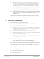
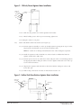
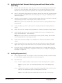
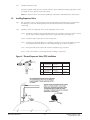
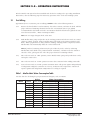
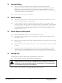
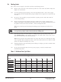
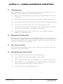
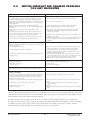
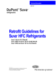
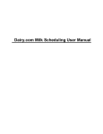
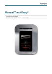
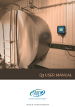
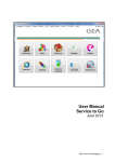
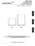
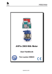
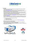
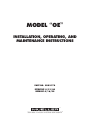
MODEL “OE”
INSTALLATION, OPERATING, AND
MAINTENANCE INSTRUCTIONS
PART NO. 8802174
EFFECTIVE 8/31/84
REPRINT 4/16/99
®
THE MILK COOLING SYSTEMS SPECIALISTSTM
®
Part No. 8802174
THE MILK COOLING SYSTEMS SPECIALISTS
TM
Table of Contents
MODEL “OE” INSTALLATION, OPERATING, MAINTENANCE, AND
SERVICE INSTRUCTIONS
Section 1.0 - Installation Instructions
Page
1.1 Installing Cooler . . . . . . . . . . . . . . . . . . . . . . . . . . . . . . . . . . . . . . . . . . . . . . . . . . . . . . . . . . . . . . . . .1
Figure 1—Installing Bulkheaded Model “OE” . . . . . . . . . . . . . . . . . . . . . . . . . . . . . . . . . . . . . . .1
1.2 Installing Agitator Motor and Assembly . . . . . . . . . . . . . . . . . . . . . . . . . . . . . . . . . . . . . . . . . . . . . . . .3
Figure 2—120 Inch/Pound Agitator Motor Installation . . . . . . . . . . . . . . . . . . . . . . . . . . . . . . . . .4
Figure 3—Hollow Shaft Gear Reducer Agitator Motor Installation . . . . . . . . . . . . . . . . . . . . . . . .4
1.3 Installing Mueller Matic® Automatic Washing System and Control Cabinet . . . . . . . . . . . . . . . . . . . . . . .5
1.4 Installing Refrigeration Unit(s) . . . . . . . . . . . . . . . . . . . . . . . . . . . . . . . . . . . . . . . . . . . . . . . . . . . . . . .5
1.5 Installing Expansion Valve . . . . . . . . . . . . . . . . . . . . . . . . . . . . . . . . . . . . . . . . . . . . . . . . . . . . . . . . .6
Figure 4—Thermal Expansion Valve (TEV) Installation . . . . . . . . . . . . . . . . . . . . . . . . . . . . . . . .6
1.6 Connecting Pre-Insulated Tubing . . . . . . . . . . . . . . . . . . . . . . . . . . . . . . . . . . . . . . . . . . . . . . . . . . . . .7
Figure 5—Suggested Refrigeration Piping for Mueller Model “OE” with Air-Cooled
Refrigeration Unit . . . . . . . . . . . . . . . . . . . . . . . . . . . . . . . . . . . . . . . . . . . . . . . . . . . . . . . . . . .7
1.7 Installing (Optional) Recording Thermometer Sensing Bulb . . . . . . . . . . . . . . . . . . . . . . . . . . . . . . . . .8
Figure 6—Recorder Bulb Channel . . . . . . . . . . . . . . . . . . . . . . . . . . . . . . . . . . . . . . . . . . . . . . .8
1.8 Wiring the System . . . . . . . . . . . . . . . . . . . . . . . . . . . . . . . . . . . . . . . . . . . . . . . . . . . . . . . . . . . . . . . .8
1.9 Test Running Cooler . . . . . . . . . . . . . . . . . . . . . . . . . . . . . . . . . . . . . . . . . . . . . . . . . . . . . . . . . . . . . .9
1.10 Test Running Washing System . . . . . . . . . . . . . . . . . . . . . . . . . . . . . . . . . . . . . . . . . . . . . . . . . . . . . . .9
Figure 7—Wiring Diagram (Single Unit) . . . . . . . . . . . . . . . . . . . . . . . . . . . . . . . . . . . . . . . . . .10
Figure 8—Wiring Diagram (Dual Unit) . . . . . . . . . . . . . . . . . . . . . . . . . . . . . . . . . . . . . . . . . . .11
Section 2.0 - Operating Instructions
2.1 First Milking . . . . . . . . . . . . . . . . . . . . . . . . . . . . . . . . .
Table 1—Mueller Matic Water Consumption Table
2.2 Subsequent Milkings . . . . . . . . . . . . . . . . . . . . . . . . . . .
2.3 Butterfat Sampling . . . . . . . . . . . . . . . . . . . . . . . . . . . .
2.4 External Measuring Gauge . . . . . . . . . . . . . . . . . . . . . . .
2.5 Emptying Cooler . . . . . . . . . . . . . . . . . . . . . . . . . . . . . .
2.6 Washing Cooler . . . . . . . . . . . . . . . . . . . . . . . . . . . . . .
Chart 1—36-Minute Time Cycle Chart . . . . . . . . . .
.
.
.
.
.
.
.
.
.
.
.
.
.
.
.
.
.
.
.
.
.
.
.
.
.
.
.
.
.
.
.
.
.
.
.
.
.
.
.
.
.
.
.
.
.
.
.
.
.
.
.
.
.
.
.
.
.
.
.
.
.
.
.
.
.
.
.
.
.
.
.
.
.
.
.
.
.
.
.
.
.
.
.
.
.
.
.
.
.
.
.
.
.
.
.
.
.
.
.
.
.
.
.
.
.
.
.
.
.
.
.
.
.
.
.
.
.
.
.
.
.
.
.
.
.
.
.
.
.
.
.
.
.
.
.
.
.
.
.
.
.
.
.
.
.
.
.
.
.
.
.
.
.
.
.
.
.
.
.
.
.
.
.
.
.
.
.
.
.
.
.
.
.
.
.
.
.
.
.
.
.
.
.
.
.
.
.
.
.
.
.
.
.
.
.
.
.
.
.
.
.
.
.
.
.
.
.
.
.
.
.
.
.
.
.
.
.
.
.
.
.
.
.
.
.
.
.
.
.
.
.
.
.
.
.
.
.
.
.
.
.
.
.
.
.
.
.
.
.
.
.
.
.
.
.
.
.
.
.
.
.
.
.
.
.12
.12
.13
.13
.13
.13
.14
.14
.
.
.
.
.
.
.
.
.
.
.
.
.
.
.
.
.
.
.
.
.
.
.
.
.
.
.
.
.
.
.
.
.
.
.
.
.
.
.
.
.
.
.
.
.
.
.
.
.
.
.
.
.
.
.
.
.
.
.
.
.
.
.
.
.
.
.
.
.
.
.
.
.
.
.
.
.
.
.
.
.
.
.
.
.
.
.
.
.
.
.
.
.
.
.
.
.
.
.
.
.
.
.
.
.
.
.
.
.
.
.
.
.
.
.
.
.
.
.
.
.
.
.
.
.
.
.
.
.
.
.
.
.
.
.
.
.
.
.
.
.
.
.
.
.
.
.
.
.
.
.
.
.
.
.
.
.
.
.
.
.
.
.
.
.
.
.
.
.
.
.
.
.
.
.
.
.
.
.
.
.
.
.
.
.
.
.
.
.
.
.
.
.
.
.
.
.
.
.
.
.
.
.
.
.
.
.
.
.
.
.
.
.
.
.
.
.
.
.
.
.
.
.
.
.
.
.
.
.
.
.
.
.
.
.
.
.
.
.
.
.
.
.
.
.
.
.
.
.
.
.
.
.
.
.
.
.
.
.
.
.
.
.
.
.15
.15
.15
.15
.16
.17
.18
.19
Section 3.0 - General Maintenance Instructions
3.1
3.2
3.3
3.4
3.5
Cooler Maintenance . . . . . . . . . . . . . . . . . . . . . . . . .
Refrigeration Unit(s) Maintenance . . . . . . . . . . . . . . .
How to Save Service Calls . . . . . . . . . . . . . . . . . . . . .
Adjusting Temperature Control Set Point . . . . . . . . . .
Mueller Matic Automatic Washing System Maintenance
Figure 9—Mueller Matic Pump Assembly . . . . .
Figure 10—Mueller Matic Control Cabinet . . . . .
Chart 2—Mueller Matic Troubleshooting Chart . . . . . .
.
.
.
.
.
.
.
.
.
.
.
.
.
.
.
.
Table of Contents - Continued
Section 4.0 - Service Instructions
4.1 Sequence of Operation . . . . . . . . . . . . . . . . . . . . . . . . . . . . . . . . . .
4.2 Thermostatic Expansion Valve . . . . . . . . . . . . . . . . . . . . . . . . . . . . .
Figure 11— “OE” Milk Cooler System Diagram . . . . . . . . . . . .
Figure 12—Accumulator-Heat Exchanger . . . . . . . . . . . . . . . .
4.3 Accumulator-Heat Exchanger . . . . . . . . . . . . . . . . . . . . . . . . . . . . . .
4.4 Refrigerant Charge . . . . . . . . . . . . . . . . . . . . . . . . . . . . . . . . . . . . .
Table 2—Milk Temperature-Suction Pressure . . . . . . . . . . . . .
Table 3—”OE” Refrigerant Charge (Estimated Start-Up Charge)
4.5 Temperature Control and Thermometer Bulbs . . . . . . . . . . . . . . . . .
.
.
.
.
.
.
.
.
.
.
.
.
.
.
.
.
.
.
.
.
.
.
.
.
.
.
.
.
.
.
.
.
.
.
.
.
.
.
.
.
.
.
.
.
.
.
.
.
.
.
.
.
.
.
.
.
.
.
.
.
.
.
.
.
.
.
.
.
.
.
.
.
.
.
.
.
.
.
.
.
.
.
.
.
.
.
.
.
.
.
.
.
.
.
.
.
.
.
.
.
.
.
.
.
.
.
.
.
.
.
.
.
.
.
.
.
.
.
.
.
.
.
.
.
.
.
.
.
.
.
.
.
.
.
.
.
.
.
.
.
.
.
.
.
.
.
.
.
.
.
.
.
.
.
.
.
.
.
.
.
.
.
.
.
.
.
.
.
.
.
.
.
.
.
.
.
.
.
.
.
.
.
.
.
.
.
.
.
.
.
.
.
.
.
.
.
.
.
.
.
.
.
.
.
.
.
.
.
.
.
.
.
.
.
.
.
.20
.20
.21
.21
.22
.22
.22
.24
.24
Section 5.0 - Service Checklist for Common Problems . . . . . . . . . . . . . . . . . . . . . . . . . . . . . . . . . . . .25
Section 6.0 - Cleaning and Maintenance of Mueller Milk Coolers
5.1 General Information . . . . . . . . . . . . . . . . . . . . . . . . . . . . . . . . . . . . . . . . . . . . . . . . . . . . . . . . . . . . .26
5.2 Suggested Cleaning and Bactericidal Treatment . . . . . . . . . . . . . . . . . . . . . . . . . . . . . . . . . . . . . . . . .26
Section 7.0 - How to Save Service Calls . . . . . . . . . . . . . . . . . . . . . . . . . . . . . . . . . . . . . . . . . . . . . . . .27
SECTION 1.0 - INSTALLATION INSTRUCTIONS
1.1
Installing Cooler
1.1.1
Remove open-type crating and packaged parts. Do not remove skids at this time.
1.1.2
Inspect cooler and report any damage to transportation company delivering the cooler. (File
claim immediately.)
1.1.3
Move cooler into milk house and position it according to approved milk house floor plans or
local dairy regulations.
Note: 36" minimum distance required between the milk outlet ferrule and the wall on 300- to
1,600-gallon coolers, with jet-tube Mueller Matic pump.
1.1.4
Bulkheading:
1.1.4.1 If the cooler is to be bulkheaded, a structural steel wall support channel and sealing
insulation strip are available (see Figure 1).
1.1.4.2 Build the slab or footings for the portion of the cooler which will be outside of the
milk room in accordance with local construction codes and large enough for the
loaded weight of the cooler.
Figure 1 - Installing Bulkheaded Model “OE”
Place Sealing Gasket
Between Pre-Formed
Channel and Cooler
8" Structural
Clearance with
3/4" Clearance
Frost Line
Varies
Gasket
Footing width and
depth per local
soil conditions.
Section A-A
Model “OE” Instructions
1
Effective August 31, 1984
Reprint April 16, 1999
1.1.5
Remove skids:
1.1.5.1 Raise one end of cooler by lifting on the end cross-brace and remove the 3/8" selftapping screws from legs on that end of the cooler using a 9/16" socket wrench.
1.1.5.2 Lower cooler and repeat the procedure on other end. (On larger coolers with more
than four legs, be sure to check all legs for screws.)
1.1.5.3 Remove cross-bracing members of the skid, leaving only the two skids on which
cooler rests.
1.1.5.4 Now raise one end of the cooler using a cradle in the shape of the cooler and pivot
the skids away from the cooler.
1.1.5.5 Lower cooler and repeat procedure on other end.
1.1.6
Installing External Measuring Gauge (optional feature):
1.1.6.1 The pyrex gauge tube is shipped in place in the gauge tube channel. Check upper
channel adjuster fitting for tightness. It should be hand tight.
1.1.6.2 Slide two hose clamps onto the shorter hose. Slip one end of the hose over fitting at
top of gauge tube, and other end of hose over the wash return elbow on top of
cooler. Tighten clamps.
1.1.6.3 Slide two hose clamps onto the longer hose. Slip end of the hose over the end of the
quick connect adapter. Slip other end of the hose over adapter at bottom of gauge
tube. Place “O” ring on quick connect to valve adapter. Install on outlet valve with
hex nut. Connect hose to outlet valve and tighten clamps.
1.1.7
Level Cooler:
1.1.7.1 Use a jack with cradle in the shape of the cooler to raise or lower each end of the
cooler. Level to comply with local regulations concerning proper height of milk outlet
and bottom of cooler from floor. Adjust legs to maintain this height.
On coolers with more than four legs, keep inner legs raised off the floor until the
levels read level and front and rear legs are adjusted to maintain that position. Then
extend inner legs to fit firmly against floor.
1.1.7.2 Double check height of outlet and bottom of cooler to be sure minimum clearance is
still correct.
1.1.7.3 As a final check, pour into cooler the exact amount of water indicated in lower left
hand corner of calibration chart which reads “Tank must be leveled to a gauge
reading of __________ with __________ gallons of water in the tank.“
To assure accuracy, use calibrated measuring cans inspected and approved by a
weights and measures inspector.
1.1.7.4 Thoroughly wash internal measuring rod with warm, soapy water. Rinse off all traces
of detergent, dry it, and dust graduated surface with Bon Ami** powder in the general
area of measurement called for on calibration chart. Since a thin coating of powder
gives the clearest reading, any excess powder should be blown off or removed by
jarring the rod.
Model “OE” Instructions
2
Effective August 31, 1984
Reprint April 16, 1999
1.1.7.5 When surface of water is quiet, carefully lower measuring rod straight down into
water so as not to disturb the surface in any way. If water surges after rod is seated in
its bracket or support, a false reading will be given. Once measuring rod is firmly
seated in its bracket or support, it should then be withdrawn promptly for reading.
1.1.7.6 For external measuring gauge, attach lower hose to the outlet valve. When surface of
water is quiet, open outlet valve slowly and let water flow into gauge tube. After
water stabilizes in tube, line up the level gauge with water level in the tube and take
reading from gauge bar on front of cooler.
1.1.7.7 If reading shows less than that called for on calibration chart, adjust rear legs of cooler
to raise the end opposite the outlet. If reading too high, lower back end of cooler by
adjusting rear legs.
**There are two types of Bon Ami now available on the market. The new type, containing
bleach, should be avoided as it will not give an accurate reading. In most areas, the old type is
difficult to obtain but it is available from Paul Mueller Company. Always insist on the Bon Ami
in the red and yellow can—the one without bleach.
1.2
Installing Agitator Motor and Assembly
1.2.1
120 Inch/Pound Agitator Motor Installation (see Figure 2):
1.2.1.1 Arrange all cap screws, lock washers, and spacer sleeves for easy access.
1.2.1.2 Remove agitator motor from shipping box.
1.2.1.3 Place agitator assembly inside cooler and insert end of agitator shaft up through round
opening directly under agitator motor. Slip neoprene agitator shaft seal and rubber
coupling ring over end of agitator shaft.
1.2.1.4 Place the three motor sleeves over internally threaded studs on the cooler.
1.2.1.5 Carefully place agitator motor on spacer sleeves and install mounting bolts with small
amount of anti-seize lubricant on threads.
1.2.1.6 Place agitator shaft over motor shaft and insert coupling pin in hole; slide coupling
ring over coupling pin to hold it in place.
1.2.2
Agitator Motor Electrical Connections:
1.2.2.1 Thread the five parts of cable fitment (adapter with “O” ring installed, grommet,
washer, and nut) onto 3-wire cable in the order shown in Figure 2.
1.2.2.2 Cut wire to proper length. Strip insulation and install wire terminals furnished in parts box.
1.2.2.3 Remove motor access plate, feed the 3-wire cable through knock-out in motor side,
and attach quick connect terminals to motor posts (either wire to either post).
1.2.2.4 Secure ground wire under ground screw on motor housing.
1.2.2.5 Screw threaded adapter into motor housing.
1.2.2.6 Slide rubber grommet into adapter.
1.2.2.7 Slide washer into adapter.
Model “OE” Instructions
3
Effective August 31, 1984
Reprint April 16, 1999
Figure 2 - 120 Inch/Pound Agitator Motor Installation
Adapter with
“O” Ring
Grommet
Washer
Nut
1.2.2.8 Slide nut into position over rubber grommet and washer.
1.2.2.9 While holding 3-wire cable to prevent twisting, tighten nut.
1.2.2.10 Replace motor access plate.
1.2.3
Motor with Hollow Shaft Gear Reducer (see Figure 3):
1.2.3.1 Position agitator assembly in cooler up through agitator opening in the top of cooler.
Slip neoprene shaft shield over the end of the agitator shaft.
Note: Be careful not to damage internal finish of the cooler during this operation.
1.2.3.2 Install the agitator weather shield kit on coolers which are bulkheaded with the
agitator outside of the milk room.
1.2.3.3 Position spacer sleeves on studs. Place motor and gear reducer in mounting position
by slipping the hollow shaft gear reducer over the agitator shaft and secure with cap
screws and lock washers.
1.2.3.4 Align hole in agitator shaft with hole in the hub of hollow shaft gear reducer and
insert drive pin.
1.2.3.5 Make wiring connections to motor as indicated in Section 1.2.2.
Figure 3 - Hollow Shaft Gear Reducer Agitator Motor Installation
Adapter with
“O” ring
Washer
Grommet
Agitator
Coupling Pin
Cap Screws
Nut
Lock
Washers
Spacer
Sleeves
Model “OE” Instructions
4
Effective August 31, 1984
Reprint April 16, 1999
1.3
Installing Mueller Matic® Automatic Washing System and Control Cabinet (Jet-Tube
Models Only)
1.3.1
Remove milk outlet valve from cooler and place in wash vat for cleaning. Insert Mueller Matic
jet-tube into cooler until rubber adapter fits tightly over outlet ferrule. Adjust legs on pump
until the center of the spray head on jet-tube is three inches above inside bottom of cooler.
1.3.2
Select a convenient location about five feet from the floor for the control box, keeping in mind
the 13-foot length of the Mueller Matic hose and pump power cord, plus availability of water
and electrical power.
1.3.3
Using the enclosed template as a guide, mark the location of the three screw holes on the wall
and, following instructions on the template, fasten cabinet to the wall.
Note: Water pressure at the Mueller Matic cabinet must be between 10 psig minimum and 75
psig maximum.
1.3.4
Connect backflow preventer to cold water hose assembly and attach to existing cold water
supply.
1.3.5
Attach cold water hose assembly to front solenoid valve connection on bottom of control cabinet.
1.3.6
Attach backflow preventer to hot water hose assembly, then connect to existing hot water
supply (140°F minimum to 170°F maximum).
Note: Because wire strainers in the solenoid valves require periodic cleaning, shut-off valves
should be installed in the connecting water lines.
1.4
1.3.7
Connect hot water hose assembly to rear solenoid valve connection on bottom of control
cabinet.
1.3.8
Connect drain valve hose to water outlet connection tube on bottom of control cabinet and
tighten hose clamp over water outlet tube as close to bottom of control cabinet as possible.
1.3.9
Feed pump power cord and grommet through opening in back of control cabinet and insert
into hole provided in bottom of top compartment. Connect wires according to wiring diagram
(see Figure 7 or Figure 8).
Installing Refrigeration Unit(s)
1.4.1
Locate refrigeration unit(s) close enough to cooler so that tubing can easily reach from unit(s)
to cooler without requiring sharp bends in the lines (see Figure 5).
1.4.2
Air-Cooled Units:
1.4.3.1 Provide a suitable solid base under protective shelter with adequate air circulation.
Note: See separate sheet, “Recommended Installation of Air-Cooled Refrigeration
Units”.
1.4.3.2 Condenser face must be accessible for periodic cleaning and located at least 18 inches
from any wall. Permanently anchor condensing units to the base.
Note: Do not install refrigeration unit(s) under same shelter with vacuum pump.
Model “OE” Instructions
5
Effective August 31, 1984
Reprint April 16, 1999
1.4.3
Mueller Fre-Heater Units:
Provide a suitable solid base in a location which is protected from freezing temperatures and
accessible to water and electrical connections.
Note: See separate sheet, “Fre-Heater Installation, Operation, and Maintenance Instructions.”
1.5
Installing Expansion Valve
1.5.1
The expansion valve is shipped in the parts box and must be installed on the cooler before
the tubing is connected. The liquid line must be flared with flare nut installed before
connecting.
1.5.2
Install the outlet of expansion valve on the liquid line of the cooler:
1.5.2.1 Install the equalizer tube (provided) between the equalizer connection on the suction
line and the external equalizer port on the expansion valve (see Figure 4).
1.5.2.2 Clean the bulb contact area of the suction tube.
1.5.2.3 Using the perforated band, nuts, and bolts provided, securely attach bulb to suction
line with the pinched-off tube on the bulb pointing up as shown in Figure 4.
1.5.2.4 Wrap the bulb and suction tube with the insulation tape provided.
1.5.2.5 Leak check all flare connections after the tubing is connected.
Figure 4 - Thermal Expansion Valve (TEV) Installation
No.
1A
1B
1C
2
Model “OE” Instructions
Description
TEV (5 hp)
AAE-5HW R-22
TEV (3.5-4 hp)
AAE-4HW R-22
TEV (3 hp)
AAE-3HW R-22
Sight Glass
6
Specifications
/2" MF inlet x 5/8"
MF outlet
1
/2" inlet x 5/8"
MF outlet
Part No.
8802357
/2" MF inlet x 5/8"
MF outlet
1
/2" MF x FF
8802355
1
1
8802356
8805416
Effective August 31, 1984
Reprint April 16, 1999
1.6
Connecting Pre-Insulated Tubing
1.6.1
Place entire coil of 3/4" or 7/8" suction line tubing beside refrigeration unit(s) and carefully
straighten tubing and feed toward cooler through pre-cut openings in milk house wall and
ceiling. Repeat above steps using 3/8" liquid line tubing.
Note: Do not remove protector caps until tubing is ready to be connected.
1.6.2
Carefully bend tubing around corners, being sure to keep each radius more than 6" in the 3/4"
line, 4" in the 7/8" line, and 3" in the 3/8" line. Severe bends may crimp tubing and restrict
refrigerant flow. The 7/8" line is a softer, bendable tubing.
1.6.3
Bring tubing down through ceiling opening to refrigerant connection on rear of cooler.
Remove protector caps and deburr tubing (see Figure 5).
1.6.4
Clean all mating surfaces of tubing with a clean cloth and sand with emery cloth if needed.
1.6.5
Solder tubing joints with low-percentage silver solder.
1.6.6
Connect tubing to refrigeration unit(s) or Fre-Heater(s) in a similar manner. Excess tubing
should be removed.
1.6.7
Repeat entire procedure for remaining refrigerant lines.
Figure 5 - Suggested Refrigeration Piping for Mueller Model “OE” with Air-Cooled
Refrigeration Unit
Use large radius bends to avoid
crimping tubing. Minimum radius bends
for 7/8" tube is 4", for 3/4" tube is 6", and
for 3/8" tube is 3".
Pre-Insulated Refrigerant Tubing
Refrigeration Unit Shelter
Provide ample air flow with large mesh
screens over vent openings. Openings
should never be smaller than condenser.
Model “OE” Instructions
7
Effective August 31, 1984
Reprint April 16, 1999
1.7
Installing (Optional) Recording Thermometer Sensing Bulb
1.7.1
Remove rubber grommet covering the raceway provided for recording thermometer sensing
bulb at rear of cooler between conduit connector and refrigerant stubs (see Figure 6).
1.7.2
Insert sensing bulb into raceway and push bulb until it is felt to firmly seat at the end of
raceway.
1.7.3
Mount and wire recording thermometer according to instructions provided.
Figure 6 - Recorder Bulb Channel
Rubber Grommet
Raceway
Bulb
Bulb Stop
1.8
Wiring the System
1.8.1
In the Mueller Model “OE” system, all internal control wiring on the control cabinet and cooler
is complete. It is only necessary to connect the control cabinet to a 230/60/1 or 200/50/1
separately fused power supply and to connect various components of the Model “OE” system
to the control cabinet.
1.8.2
Select a main circuit breaker or fused disconnect switch and service wires of sufficient size to
carry the total load and to comply with local regulations. Install a separate circuit breaker or
fused disconnect switch for the control cabinet with sufficient capacity for the agitator motor
and Mueller Matic. Do not include any appliances or outlets on these circuits. For increased
safety and improved appearance, enclose all external wiring in electrical conduit.
1.8.2.1 According to the National Electrical Code, the branch circuit to a refrigeration unit may
be protected with a fuse or circuit breaker 175% of the unit full load ampere rating,
provided that the wire size is adequate.
Note: The effect of abnormally high or low temperatures at circuit breakers should be
considered if a thermal, adjustable-trip type is used.
1.8.2.2 Model “OE” installations should be wired to provide the required capacities, otherwise
the compressor load with large quantities of warm milk may cause branch circuit
protectors to open unnecessarily. The compressor motors used have built-in overload
protection and the branch circuit protector need only protect against grounds and
shorts.
1.8.2.3 Your electrical power supplier should be advised of the anticipated increase in
electrical load with the cooler in use.
Model “OE” Instructions
8
Effective August 31, 1984
Reprint April 16, 1999
1.9
1.10
Test Running Cooler
1.9.1
With control cabinet selector switch in “OFF” position and timer knob in “OFF” position, turn
disconnect switches to the “ON” position.
1.9.2
Move selector switch to “COOL” position. Agitator will turn and refrigeration unit(s) will start.
Connect refrigeration drum and slowly open suction service valve to charge system. Place
sufficient water in cooler to cover agitator blade. The temperature control will shut off unit(s)
when the water is cooled to approximately the temperature control cut-out point (37°F
recommended).
1.9.3
After water has been cooled and unit(s) stop, advance agitator timer knob to “ON” position.
The agitator will run for 3 minutes, but the refrigeration unit(s) will not start until the water is
warmed to approximately the temperature control cut-in point. Add warm water very slowly
to restart unit(s), which should occur at approximately 40°F. Adjustment of temperature
control may be necessary. Consult “Maintenance Instructions” for proper procedure.
Test Running Washing System
1.10.1
Remove outlet valve from cooler and insert jet-tube into cooler outlet until rubber adapter fits
tightly over outlet ferrule.
1.10.2
Place vent assembly over milk inlet opening.
1.10.3
Remove the bowl labeled “Detergent,” add detergent, and replace bowl.
1.10.4
Remove the bowl labeled “Acid or Sanitizer,” add non-foaming food-grade acid cleaner and
replace bowl.
1.10.5
Move control cabinet selector switch to “WASH” position and advance Mueller Matic timer
knob on control cabinet clockwise only to start system.
1.10.6
Observe entire operation through one complete cycle to see that each function takes place as
marked on the Mueller Matic timer dial plate. Check all water connections for leaks. Observe
spray pattern to see that all areas of cooler are being covered. Direction of spray can be
changed by raising or lowering the pump on the adjustable leg stand. After locating pump
assembly in the proper position, drill two No. 20 holes (with drill bit provided) in the tubular
legs through the holes in the leg bracket. Install self-tapping screws to prevent leg slippage
and misalignment of the pump assembly.
1.10.7
If at any time your Mueller Matic does not operate properly, consult “Mueller Matic
Troubleshooting Chart” in the “Maintenance Instructions.”
1.10.8
Important Notes:
1.10.8.1 To stop operation of the Mueller Matic, move timer knob on control cabinet clockwise
only to “OFF” position.
1.10.8.2 The Automatic Washing System will not operate when the selector switch on the
control cabinet is in the “OFF” or “COOL” position.
“OE” Instructions
9
Effective August 31, 1984
Reprint April 16, 1999
Figure 7 - Wiring Diagram (Single Unit)
Part No. 8802133
Model “OE” Instructions
10
Effective August 31, 1984
Reprint April 16, 1999
Figure 8 - Wiring Diagram (Dual Unit)
Part No. 8802134
Model “OE” Instructions
11
Effective August 31, 1984
Reprint April 16, 1999
SECTION 2.0 - OPERATING INSTRUCTIONS
After the Model “OE” System has been installed and checked according to the preceding “Installation
Instructions,” take the following steps for satisfactory operation of the cooler and washing system.
2.1
First Milking
Approximately 10 to 15 minutes prior to milking, sanitize cooler in the following manner:
2.1.1
Remove the bowl labeled “Acid or Sanitizer,” discard its contents, and rinse the bowl. Add the
proper amount of sanitizing solution based on the concentration (ounces per gallon)
recommended for the brand used. The concentration should be based on the gallons of rinse
water shown in Table 1, “Water Consumption Table.”
Note: Do not empty detergent bowl at this time.
2.1.2
With Mueller Matic pump and jet-tube in the washing position and selector switch on control
cabinet in “Wash” position, advance Mueller Matic timer knob to the position marked “Acid
Rinse.” While preparations are being made for milking, sanitizing will be completed, and the
Mueller Matic will automatically drain the cooler and shut off.
Note: If preferred, sanitizing solution may be placed directly in the cooler by advancing
Mueller Matic timer knob to the position marked “Acid Rinse,” and after water has started to
enter the cooler, placing into the cooler the proper amount of sanitizing solution.
2.1.3
Move selector switch to “OFF” position, remove Mueller Matic pump and jet-tube from cooler,
and replace outlet valve.
2.1.4
Move selector switch to “COOL” position no more than 5 minutes before adding warm milk.
2.1.5
Leave selector switch in “COOL” position. Automatic timer will operate agitator independently
of refrigeration unit(s) for 3 minutes out of every 30 minutes. The temperature control will
operate agitator and refrigeration unit(s) whenever cooling is required.
Table 1 - Mueller Matic Water Consumption Table
Use this chart for calculating the proper amount of detergent, acid, or sanitizer.
Model
76 Series
326 Series
727 Series
Orifice
1.2 gpm
1.5 gpm*
2.6 gpm*
3.0 gpm*
1.5 gpm
1.8 gpm*
2.6 gpm*
3.0 gpm*
1.5 gpm
1.8 gpm*
2.6 gpm*
3.0 gpm*
Orifice
Water Consumption
Color Code Detergent Wash Cycle Final Rinse Cycle
HN
9.4 gallons
8.8 gallons
HM
11.7 gallons
11.0 gallons
HR
20.3 gallons
19.0 gallons
HH
23.5 gallons
22.0 gallons
HM
11.7 gallons
11.0 gallons
HY
14.0 gallons
13.1 gallons
HR
20.3 gallons
19.0 gallons
HH
23.5 gallons
22.0 gallons
HM
23.4 gallons
21.9 gallons
HY
28.0 gallons
26.3 gallons
HR
40.6 gallons
38.0 gallons
HH
46.8 gallons
43.8 gallons
*Optional Orifice
Model “OE” Instructions
12
Effective August 31, 1984
Reprint April 16, 1999
2.2
2.3
2.4
2.5
Subsequent Milkings
2.2.1
Just prior to milking, turn agitator timer to delayed start. Agitator will not run for
approximately 10 minutes. The agitator will then start and run for approximately 3 minutes
blending warm and cold milk. During this period, warm milk entering cooler will cause
refrigeration unit(s) to start. Agitator and refrigeration unit(s) will continue to run until milk is
cooled to the temperature control settings.
2.2.2
Leave selector switch in “COOL” position.
Butterfat Sampling
2.3.1
After pick-up tank truck driver records the temperature and amount of milk in the cooler, he
will want to agitate milk for a butterfat sample.
2.3.2
To agitate milk for a sample, turn agitator timer knob clockwise to “ON” position, while
selector switch is in “COOL” position. The agitator will run for approximately 3 minutes before
shutting off automatically. Agitation can be halted by advancing timer knob. Coolers smaller
than 1,600 gallons should be agitated through two time cycles. Agitate 1,600-gallon coolers
through three time cycles.
External Measuring Guide (Optional)
2.4.1
After determining milk volume, close milk outlet valve on cooler.
2.4.2
Disconnect hose from fitting on outlet valve and dispose of the milk which drains from the
hose and the tube.
2.4.3
Remove hex nut and quick-connect tube coupling from outlet valve and place in wash vat for
hand cleaning.
2.4.4
After milk has been removed from cooler, remove outlet valve and place in wash vat for hand
cleaning.
2.4.5
If gauge is used between milkings and cooler will not be washed immediately, close outlet
valve and dispose of milk in gauge tube. Properly clean the gauge tube by disconnecting
hoses from cooler and flushing from the top to remove milk residue, then reconnect the hoses.
Emptying Cooler
The following steps must be taken before pumping milk out of the cooler.
2.5.1
!
▲
2.5.2
Model “OE” Instructions
Move “Selector” switch on control cabinet to “OFF” position.
CAUTION: Be sure vent assembly is over milk inlet opening and release hold-down
clamps on manhole cover to provide additional venting. To equalize pressure inside
and outside of cooler during filling, emptying, and washing, it is recommended that
vent assembly be kept on the inlet at all times.
Empty cooler and rinse out remaining milk solids with tepid water.
13
Effective August 31, 1984
Reprint April 16, 1999
2.6
Washing Cooler
After cooler has been emptied, it should be washed in the following manner:
2.6.1
Remove outlet valve from cooler and insert jet-tube into cooler outlet until rubber adapter fits
tightly over outlet ferrule.
2.6.2
To wash external gauge tube during cooler wash with Mueller Matic, connect lower gauge
hose to fitting on side of Mueller Matic pump assembly. Be sure upper hose is inserted on top
of cooler.
2.6.3
Be sure the vent assembly is properly installed to equalize pressure inside and outside of
cooler during washing.
2.6.4
Remove the dispenser bowl labeled “Detergent” and discard its contents. Add the proper
amount of detergent recommended for the brand used. The concentration should be based on
the gallons of wash water shown in Table 1, “Water Consumption Table.”
Note: Save yourself repeated measuring by marking proper detergent and acid levels on
bowls.
▲
!
2.6.5
CAUTION: Never mix chlorinated sanitizers or detergent with acid. Be sure that there
is no previous product residue in the bowl before adding acid.
Move Selector switch on control cabinet to “WASH” position and turn Mueller Matic timer
knob clockwise only to start automatic wash system. The Mueller Matic will pre-rinse, wash,
rinse, and acid rinse, then turn off automatically.
Note: During operation of the Mueller Matic, the pump will run for 30 seconds after the drain
valve is opened. This is normal (see Chart 1, “Time Cycle Chart”) and serves to flush out small
particles of sediment remaining in the cooler.
2.6.6
Sanitizing should be done immediately before milking according to procedures outlined under
“Operating Instructions.”
2.6.7
If at any time the Mueller Matic does not operate properly, consult the “Mueller Matic
Troubleshooting Chart.”
Chart 1 - 36-Minute Time Cycle Chart
36-Minute Time Cycle Chart
■ On ❑ Off
Circuit
0 . . . . . . . .5 . . . . . . . .10 . . . . . . .15 . . . . . . .20 . . . . . . . .25 . . . . . . .30 . . . . . . .35
1A Rinse Water
2A Wash Water
3A Rinse-Acid/
Sanitizer
6
Pump
4A TM
Model “OE” Instructions
14
Effective August 31, 1984
Reprint April 16, 1999
SECTION 3.0 - GENERAL MAINTENANCE INSTRUCTIONS
3.1
Cooler Maintenance
Although Mueller Milk Coolers are designed and built to provide years of trouble-free service, the
following precautions and maintenance schedule should be observed:
3.2
3.1.1
Always rinse out cooler immediately after emptying to be sure that milk does not dry on the
cooler surface.
3.1.2
Keep all surfaces of cooler, inside and outside, clean and free of deposits of foreign matter.
3.1.3
Do not allow tools, clamps, or any wet objects to lie on the surface for a prolonged period of time.
3.1.4
Do not enter cooler with shoes on or allow surface to be scratched in any way.
3.1.5
Use only those cleaning solutions or materials specifically recommended for use on stainless
steel. Never use steel wool, files, coarse sandpaper, or emery cloth.
3.1.6
For detailed cleaning and maintenance instructions, see section entitled, “Cleaning and
Maintenance of Mueller Milk Coolers.”
Refrigeration Unit(s) Maintenance
Mueller Model “OE” refrigeration units require little maintenance. However, to ensure that they are
able to do the best cooling job possible, air-cooled condensers must be kept clean and well ventilated
and Mueller Fre-Heaters must have a continuous supply of clean water. A water filter, and, in “hard”
water areas, a water softener are recommended.
3.3
How to Save Service Calls
If your Mueller Model “OE” Milk Cooler fails to operate, consult “How to Save Service Calls” in this
manual before calling your serviceman.
3.4
Adjusting Temperature Control Set Point
3.4.1
Turn off all electrical power to the cooler and condensing unit(s).
3.4.2
Remove stainless steel access plate on right front corner of cooler.
3.4.3
Remove temperature control cover and turn adjusting screw to a colder or warmer setting.
3.4.4
Replace rubber access cover and stainless steel access plate making sure the sealing gasket is
spread evenly along all edges of plate for a positive water seal.
3.4.5
Turn on power to the cooler and refrigeration unit(s).
Model “OE” Instructions
15
Effective August 31, 1984
Reprint April 16, 1999
3.5
Mueller Matic Automatic Washing System Maintenance
Your Mueller Matic is engineered to give you maximum service with minimum care. In order to ensure
years of trouble-free service, the following periodic inspections and servicing should be performed:
3.5.1
Check hoses for breaks or cracks and hose clamps for loose connections.
3.5.2
Clean water supply strainers regularly as follows:
3.5.2.1 Close water supply valves and remove hose assemblies.
3.5.2.2 Remove, clean, and replace strainers.
3.5.2.3 Reinstall hose assemblies.
3.5.2.4 Open water supply valves.
3.5.3
Clean dispenser bowl strainers as follows:
3.5.3.1 Remove bowl.
3.5.3.2 Remove bowl strainer retainer ring and bowl strainer.
3.5.3.3 Clean strainer screen and install in the reverse order.
3.5.3
Auto-drain valve assembly:
The auto-drain valve assembly (see Figure 9) is activated by water pressure. It can be
disassembled for service or replacement of parts.
The drain valve assembly controls the flow of water into the washing system. Amounts are
metered by a neoprene flow-control orifice and will deliver proper amounts of water with
pressures from 10 psig minimum to 75 psig to a maximum of 170°F.
Note: Water pressures over 75 psig will require a pressure regulator; otherwise, damage to the
water solenoid valves and drain valve may result.
3.5.4
The timer is a precision electrical instrument. Do not attempt to disassemble the timer.
3.5.5
The Time Cycle Chart (see Chart 1) shows the sequence of operations as governed by the
timer. It indicates when each circuit is energized and is keyed to the terminals as numbered on
the timer and wiring diagrams.
3.5.6
Oil top bearing in the pump motor once per year.
3.5.7
If at any time your Mueller Matic does not operate, consult the “Troubleshooting Chart” in this
manual.
Model “OE” Instructions
16
Effective August 31, 1984
Reprint April 16, 1999
Figure 9 - Mueller Matic Pump Assembly
Piston and Flow Control Orifice
Seal Retainer
Housing
Piston Bonnet
Piston Diaphragm
Pump Motor
Piston Nut
Seal, Rotary
Stem
Pump
Housing
Gasket
Impeller
Piston Jacket
Valve Spring
Auto Drain
Valve Assembly
Drain Valve Plug
Drain Valve Gasket
Jet-Tube Assembly
Drain Valve Gasket
Tie Band Clamp
Adapter Clamp
Rubber Outlet
Ferrule Adapter
Model “OE” Instructions
17
Effective August 31, 1984
Reprint April 16, 1999
Figure 10 - Mueller Matic Control Cabinet
3345
Terminal Block, 6-Pole
Model “OE” Instructions
18
Effective August 31, 1984
Reprint April 16, 1999
Chart 2 - Mueller Matic Troubleshooting Chart
Trouble
1. Washer will not operate in any
cycle.
Cause
a. Blown fuse.
b. Toggle switch on control cabinet in
“OFF” or “COOL” position.
c. Main switch open.
d. Loose wire.
e. Timer defective.
2. Drain valve will not stay closed.
3. Drain valve will not open.
4. Pump will not prime.
a. Insufficient or irregular water
pressure.
b. Defective timer.
c. Defective drain valve.
a. Weak or broken water valve spring.
b. Diaphragm binding in piston jacket
or stem binding in stem guide.
c. Obstruction in orifice.
a. Insufficient water.
b. Water pressure too low.
c. Water pressure too high.
5. Pump loses prime.
a. Loss of water from drain valve.
b. Loss of water around cooler cover.
6. Water leaks around dispenser bowl.
7. Pump will not start.
a.
b.
c.
a.
“O” ring worn.
Irregular lid.
Dry “O” ring.
No power to pump.
b. Defective motor or capacitator.
8. Water not hot enough.
9. Not enough water (see Table 2).
a. Too small or defective hot water
heater.
b. Long piping run from hot water
heater.
a. Clogged flow-control orifice.
b. Solenoid not opening.
c. Drain valve leaking.
10.Areas of cooler not being
cleaned.
d. Strainer plugged.
e. Plugged pipe or hose.
a. Improper spray pattern.
b. Plugged spray head.
Model “OE” Instructions
19
Correction
a. Replace fuse.
b. Move selector switch to “WASH”
position.
c. Close switch.
d. Open control cabinet and check
using wiring diagram.
e. Test for 230V across 1 and TM
terminals. Replace if 230V is present.
a. Increase water supply pressure.
b. Check for correct time interval as
shown on “Time Cycle Chart,”
Chart 1.
Note: Drain valve closes when
either wash or rinse water is on.
c. See Figure 9.
a. Replace spring.
b. Lubricate diaphragm and stem or
replace the diaphragm.
c. Disassemble and remove
obstruction.
a. Knob turned too far. (First rinse
only affected.)
Clean screens; straighten hose.
Check timer against time chart in
manual. See Chart 1.
b. Raise pressure at water supply
pump control if necessary.
c. Install Part No. 30729 clip in drain
valve plug.
a. Check water pressure.
Check water pressure tank.
b. Adjust spray to minimize loss of
water at cooler openings.
Note: Larger flow control(s) are
provided for special field problems
where an excessive amount of
water is lost around the covers. See
Table 1.
a. Replace.
b. Replace.
c. Lubricate with food-grade lubricant.
a. Check pump electrical connections.
Check wiring against diagram. Check
timer.
b. Check for open winding, shorts, or
grounds.
a. Repair or replace heater.
b. Insulate pipes or raise temperature
setting at hot water tank.
a. Remove drain valve assembly and
clean orifice.
b. Check solenoid coil. Check wiring.
c. Increase water pressure to close
plug. Align plug with seat.
d. Remove and clean.
e. Remove and clean.
a. Adjust legs on pump and observe
spray pattern.
b. Reverse flush.
Effective August 31, 1984
Reprint April 16, 1999
SECTION 4.0 - SERVICE INSTRUCTIONS
4.1
Sequence of Operation
The Mueller Model “OE” Milk Cooler features a thermostatic expansion valve refrigeration system
controlled by a mechanical temperature control on the cooler. When the temperature control sensing
bulb (located in a bulb clip on the front head of the cooler) senses an increase in temperature, the
contacts in the control close. This energizes the magnetic coil of the cooling relay in the wall-mounted
control cabinet, which in turn energizes the agitator relay in the control cabinet and the refrigeration
unit contactor on the unit, starting the agitator motor and the refrigeration unit. On dual unit coolers,
the time delay switch energizes the refrigeration unit contactor after a 40 second delay, starting the
second unit.
4.2
Thermostatic Expansion Valve
4.2.1
The thermostatic expansion valve ensures that the correct amount of liquid refrigerant is
delivered to the evaporator coil by sensing and controlling the amount of superheated vapor
in the evaporator. The superheated vapor being that refrigerant that has been evaporated and
further heated above the evaporation point of the refrigerant. Maximum efficiency is obtained
by minimizing the amount of superheated vapor refrigerant in the evaporator, since liquid
refrigerant removes heat more efficiently from the milk than superheated refrigerant vapor.
The expansion valves used on Model “OE” Mueller Milk Coolers are preset to obtain 4°F
superheat with a 38°F product.
Note: Before checking expansion valve superheat, be sure that the unit is properly charged
with refrigerant (see Section 4.4).
4.2.2
To determine at what superheat the valve is operating, connect a suction gauge to the external
equalizer line of the expansion valve. With the machine running and the suction pressure
approximately stable, take an accurate suction line temperature reading at the expansion valve
bulb location. At the same time, take a suction pressure reading. Refer to a refrigerant
“Temperature-Pressure Chart” and convert the suction pressure reading to an equivalent
saturation temperature. Subtract this reading from the suction line temperature reading and the
difference will be the operating superheat. For example:
REFRIGERANT-22
Suction Line Temperature . . . . . . . . . . .31°F
Suction Pressure . . . . . . . . . . . . . . . .51 psig
Equivalent Saturation Temperature . . . .27°F
31°F - 27°F = 4°F Superheat
4.2.3
As a guide, when the temperature of milk in the cooler is 38°F, normal pressure in the
equalizer line will range from 51 to 54 psig for Refrigerant-22. If the suction pressure at this
temperature (38°F) drops below 41 psig for Refrigerant-22, immediate steps should be taken to
determine the cause. Usually it will be found that the superheat is too high. Important points
to remember about checking expansion valves include:
4.2.3.1 There must be good thermal contact between the expansion valve bulb and the
suction tube.
4.2.3.2 Superheat should be checked in the 38° to 40°F milk temperature range. Problems
may not be evident if superheat is checked at higher milk temperatures.
4.2.3.3 Increased superheat reduces the suction pressure. Decreased superheat setting will
raise the suction pressure.
Model “OE” Instructions
20
Effective August 31, 1984
Reprint April 16, 1999
4.2.3.4 Suction temperature readings for determining the superheat should be taken on the
suction line at the expansion valve bulb location. The evaporator surface should be at
least 85% covered with water or milk when taking superheat readings.
4.2.3.5 If it is determined that the expansion valve is not properly controlling the superheat,
the valve should be replaced. A typical expansion valve failure is due to loss of charge
in the expansion valve bulb which allows the valve to close and results in low suction
pressure and high superheat.
Figure 11 - “OE” Milk Cooler System Diagram
Figure 12 - Accumulator-Heat Exchanger
Liquid In
Liquid Coil
Suction Out
Suction In
Liquid Out
Liquid Coil
Strainer
Oil Return Orifice
Model “OE” Instructions
21
Effective August 31, 1984
Reprint April 16, 1999
4.3
4.4
Accumulator-Heat Exchanger
4.3.1
The accumulator-heat exchanger is a device that has both low side and high side functions. Its
function in the low side of the system is to collect liquid refrigerant between the evaporator
and the compressor. It is designed so that liquid refrigerant is collected and vaporized before it
is returned to the compressor. Oil is returned to the compressor through an orifice in the
bottom of the suction J-tube (see Figure 12).
4.3.2
Its function in the high side is to provide additional sub-cooling of the high side liquid
refrigerant between the condenser and the expansion valve. This sub-cooling occurs as the
high side liquid travels through the liquid coil (pancake coil) located in the bottom of the
accumulator-heat exchanger, which during operation is exposed to cold low side liquid
refrigerant. This additional subcooling ensures that a solid column of liquid refrigerant enters
the expansion valve for proper valve operation and it improves the performance by
minimizing the amount of flash gas in the evaporator.
4.3.3.
The heat exchange that occurs between the warm high side liquid passing through the
pancake coil and the cold low side liquid that is exposed to the pancake coil serves to
vaporize the low side liquid.
Refrigerant Charge
As a general indicator, the following chart shows normal suction pressures at the Schraeder fitting on the
suction line at the unit. Low suction pressure could be caused by a low refrigerant charge or filled
thermostatic expansion valve and, if suspected, the refrigerant charge should be verified with the weigh-out,
weigh-in method in the next section.
Table 2 - Milk Temperature-Suction Pressure
Milk Temperature
(Fahrenheit)
75°
60°
50°
40°
38°
4.4.1
Normal Suction
Pressure (psig)
95 - 105
75 - 85
63 - 73
52 - 57
49 - 55
Weigh-Out/Weigh-In Method
4.4.1.1 Use only clean Refrigerant-22 cylinders.
4.4.1.2 Check the refrigerant smell (burned refrigerant has a distinctive smell) and/or use an
acid kit to determine if the system is contaminated.
4.4.1.3 If the refrigerant is contaminated use a cylinder to reclaim the refrigerant and send it
to a reclaim company.
4.4.1.4 Install service gauges on the system. Attach the low side gauge at the Schraeder valve
on the suction line quick coupling and the high side gauge at the service port on the
liquid line shutoff valve. The charging hose should be attached to a clean, empty
recovery cylinder.
4.4.1.5 Check the refrigerant for contamination, purge the service gauges and hoses, and
weigh the empty cylinder.
Model “OE” Instructions
22
Effective August 31, 1984
Reprint April 16, 1999
4.4.1.6 With the unit running, close the liquid line shutoff valve (turn clockwise) about
halfway. Next, open the high side service gauge valve. This will allow liquid
refrigerant to flow from the system into the empty cylinder. When suction pressure
begins to drop, close liquid line valve.
4.4.1.7 Observe the low side service gauge. When the low side pressure is down to 2 or 3
psig, the unit should cut off on the low pressure control. Do not pull the system into a
vacuum. If the unit does not cut off on the low pressure control, turn it off at the
nearest disconnect.
If you have not already done so, turn the unit off at the control cabinet. Recover the
remaining refrigerant from the system. This will usually be from 1/2 to 1 pound. Weigh
the refrigerant cylinder. The difference between the beginning and final weight is the
total charge which was in the system.
4.4.1.8 If the system is found to be undercharged, check thoroughly for leaks. Any leaks
should be repaired, the filter-drier changed, and evacuated before recharging with the
proper charge of refrigerant. If found to be overcharged, it is usually the result of
improper service procedures.
4.4.1.9 Consult “OE” Refrigerant Charge, Table 3, for the correct charge before recharging the
system. After determining the proper charge for the unit, weigh this amount of
refrigerant into the system using the following procedure:
4.4.2
4.4.1.9.1
Weigh the cylinder to determine the starting weight.
4.4.1.9.2
With the unit still turned off at the control cabinet and the cylinder in the
liquid feed position, open both service gauge valves and allow liquid
refrigerant to flow into the system. The cylinder should be on a scale during
this operation so the amount of refrigerant being put into the system can be
observed.
4.4.1.9.3
When the system and cylinder pressures equalize, if the system has not
reached the full charge, close the high side service gauge valve and start the
unit. You can then pull the remaining charge into the system through the
Schraeder valve on the suction line quick coupling. Do not exceed the
charge indicated in “OE Refrigerant Charge,” Table 3.
4.4.1.9.4
Before disconnecting the service gauges, operation of the high pressure
control should be checked in the following manner. On air-cooled units,
cover the top 3/4 of the condenser and observe the head pressure. The high
pressure control should cut the unit off at 405 psig ± 10 psig. If the high
pressure control fails to cut the unit off, it should be adjusted or replaced.
4.4.1.9.5
Disconnect service gauges, replace all electrical covers, remove obstructions
used to check the high pressure control on air-cooled units—turn on inlet
water on Fre-Heater units, and be sure all electrical disconnects are on
before leaving the unit.
Charging to Clear Sight Glass
4.4.2.1 The amount of charge shown in Table 3 should be adequate for most installations;
however, there are some installations which will require additional refrigerant charge.
These installations will require using the sight glass to indicate when the system is
properly charged.
Model “OE” Instructions
23
Effective August 31, 1984
Reprint April 16, 1999
4.4.2.2 To correctly charge a system using the sight glass, the product in the cooler should be
between 38° to 42°F. Slowly add refrigerant until the sight glass is just clear (an
occasional bubble may be seen—this is normal). Keep in mind that the system will
require slightly more refrigerant in the winter than in the summer.
4.4.2.3 The sight glass must be located as close to the inlet to the thermostatic expansion
valve as possible. There must not be any valves or filter dryer between the sight glass
and the TXV.
4.4.2.4 Small bubbles moving very fast through the sight glass does not necessarily indicate a
low charge. This is more likely an indication of the superheat set too low.
Table 3 - “OE” Refrigerant Charge (Estimated Start-Up Charge)
Unit
HP
3
4
5
4.5
Air-Cooled Unit
Refrigerant Charge (Lbs.)
11
12
13
Temperature Control and Thermometer Bulbs
The temperature control is located behind an access plate on the right front leg channel of the cooler,
and the thermometer is mounted in the front head of the cooler. Both sensing bulbs are located in
raceways on the bottom of the front head, just to the right of the outlet valve.
4.5.1
Replacing Temperature Control Bulb:
4.5.1.1 Remove temperature control access plate from leg channel and pull temperature
control capillary tube and sensing bulb from raceway in the leg channel opening.
4.5.1.2 Insert bulb for new temperature control in raceway of leg channel opening and push
in place, after coating bulb with heat conductive compound (such as Presstite #446).
See Service Bulletin 1098 in milk cooler section for proper installation.
4.5.2
Replacing Thermometer Bulb:
4.5.2.1 Remove screws holding dial thermometer and pull sensing tube and bulb upward
from raceway.
4.5.2.2 After coating bulb with heat conductive compound (such as Presstite #446), insert new
bulb through thermometer mounting hole and feed it down to bottom of raceway. See
Bulletin 1098.
Model “OE” Instructions
24
Effective August 31, 1984
Reprint April 16, 1999
5.0
SERVICE CHECKLIST FOR COMMON PROBLEMS
YOU MAY ENCOUNTER
Trouble
Remedy
1. Problem: Compressor “Running Too Long”
A. Low refrigerant charge will be indicated by bubbles or “smoky”
condition in liquid sight glass, low suction and head pressure.
B. High head pressure and long running time may be caused by dirty,
clogged-up or blocked air-cooled condenser, or condenser fan or
fans not running.
C. High head pressure caused by overcharge of refrigerant.
D. High head pressure caused by air or other non-condensable gases
in system.
E. High head pressure caused by scaling of Fre-Heater heat
exchanger.
F. Loss of compressor pumping capacity due to leaky, burned, or
worn out compressor valve reeds. This will be indicated by low
head pressure and higher than normal suction pressure.
G. Tubing where refrigerant leaves cooler is too warm or too cold.
A. Check refrigerant charge by weigh-in, weigh-out method.
B. Clean condenser. Check fans.
C. Check refrigerant charge by weigh-in, weigh-out method.
D. Remove refrigerant charge, reevacuate, and recharge.
E. Descale heat exchanger as directed in Fre-Heater Instructions.
F. Consult the Sales/Service Manual for check on this. Replace
Compressor if required.
G. Expansion valve superheat improperly set or uneven refrigerant
distribution to circuits.
H. Defective expansion valve, poor contact between bulb and suction
tube, or temperature control set too cold. Agitator motor is not
running.
H. Ice on evaporator causing loss of heat transfer efficiency.
2. Problem: High Blend Temperature. A high blend temperature of
milk on subsequent milkings can be caused by one or more of the
following problems:
A. Loss of refrigeration capacity.
A. Any one of the causes listed for “Compressor Running Too Long”
could be applicable as a possible reason for loss of capacity.
B. Temperature controller set too high, too large differential, or
defective temperature controller. Also, start agitator with switch at
beginning of milk adding period.
C. Set temperature control dial colder. Check temperature of milk
when condensing unit cuts “OFF” and “ON”. If differential is more
than 4°F, inspect contact of bulb against cooler. Recheck
differential and replace temperature control if necessary.
B. Condensing unit not starting soon enough.
C. Temperature of milk in cooler not low enough at beginning of the
adding period.
3.
A.
B.
C.
Problem: Compressor will not start, no motor hum.
Tripped circuit breaker.
Disconnect switch open.
Open line circuit.
A. Reset. If it trips again, check for line shorts.
B. Close switch.
C. Check wiring and fuses.
4. Problem: Compressor will not start; motor hums.*
A. This could be one of many things, but most probably electrical.
A. Check the Technical Data Section of the Sales/Service Manual.
5. Problem: Compressor runs and stops intermittently before
milk is cooled down.*
A. If compressor is starting and stopping and the refrigerant solenoid
valve opening and closing, the trouble is probably a defective
temperature controller. (When solenoid valve opens or closes a
definite “click” will be heard.
B. Compressor cycling on overload due to high operating pressures.
C.
Cut-off point on low pressure switch set too high.
A. Check temperature controller and replace if required.
B. Clean the condenser. Make sure there is plenty of unrestricted air
flow.
C. Set to cut-off at 2 psig for R-12 or R-22. Check for adequate
refrigerant charge.
D. Replace.
E. Replace drier (if filter-drier is in suction line add a drier to the liquid
line.)
D. Defective low pressure switch.
E. Moisture in system.
*There are many different things that can cause a compressor not to run or to go on and off periodically. Some of the
more obvious ones are listed here. For a more detailed analysis of compressor starting and running problems, see the
Technical Data Section of the Sales and Service Manual.
The above list does not encompass all of the electrical and mechanical problems that may be encountered in
servicing a condensing unit. 90% of compressor starting and running difficulties will normally be electrical. Starting
or running capacitors, relays, and overload protectors should be all carefully checked in accordance with the
Technical Data Section of the Sales/Service Manual or replaced in case of doubt.
Model “OE” Instructions
25
Effective August 31, 1984
Reprint April 16, 1999
SECTION 6.0 - CLEANING AND MAINTENANCE OF
MUELLER MILK COOLERS
6.1
General Information
All metal product contact surfaces of this equipment are manufactured from one of the 300 series
stainless steels. These alloys are suitable for use with most food and similar products. Because it is
easy to clean and maintain, it will remain bright and spotless by following these suggestions:
DON’T let deposits of foreign matter of any kind remain on the surface for more than several hours at
any one time.
DON’T let pails, tool, or wet objects lie on the surface even overnight.
DON’T enter the cooler with shoes on or scratch the surface with files, steel wool, coarse sand paper,
or emery cloth. Use only stainless steel sponges (available at most hardware stores) for
removing stubborn deposits.
DON’T use more detergent or sanitizing compound than called for in manufacturer’s directions. This
not only saves materials, but also prevents dulling the metal surface or possible corrosion.
DON’T put detergent or concentrated sanitizing compounds in empty cooler.
HAVE WATER IN TANK FIRST.
DON’T let cleaning or sanitizing solutions remain in cooler for more than 20 minutes.
DON’T splash or permit such solutions to dry on surface. It’s good practice to sanitize just before
product enters coolers.
DON’T let water evaporate in cooler. Salts settle out of most waters and may stain the surface. Drain
completely.
DON’T apply pressure in cooler.
6.2
Suggested Cleaning and Bactericidal Treatment
6.2.1
Rinse out solids, foam, etc., with cold water immediately after product is removed.
6.2.2
Before washing, rinse with warm water.
6.2.3
Dissolve cleaning compound in container of warm water. Use the amount of cleaning
compound recommended by the chemical manufacturer.
6.2.4
An acidified rinse may be used as a final rinse without harming the surface. Follow the
chemical manufacturer’s instructions carefully.
6.2.6
Sanitize the tank immediately before product enters. Brush or spray all product contact
surfaces with 200 ppm (maximum) chlorine solution or other approved sanitizing compounds.
6.2.7
“OE” coolers are designed to be cleaned by spray equipment (such as the Mueller Matic
Automatic Washing System). Follow the spray equipment manufacturer’s instructions.
The above suggestions are taken from publications of Allegheny Ludlum Steel Corporation, National Association
of Dairy Equipment Manufacturers, Food Management, and the American Iron and Steel Institute.
Model “OE” Instructions
26
Effective August 31, 1984
Reprint April 16, 1999
SECTION 7.0 - HOW TO SAVE SERVICE CALLS
7.1
General Information
If your Mueller Milk Cooler fails to operate properly, check the following before requesting service:
7.1.1
Be sure main electrical switch is closed and switch on control box on wall is in “Cool”
position.
7.1.2
Check all fuses, including the large cartridge fuses, in the main entrance panel. Keep extra
fuses of the right size on hand.
7.1.3
Check air-cooled condenser to be sure it is not partially clogged with dust, lint, or debris. It
can be brushed, vacuumed, or blown-out with compressed air to clean. It is important that the
condenser be kept clean and well-ventilated. Condenser “fins” should be straight and in good
condition.
7.1.4
If your cooler fails to operate during or immediately after an electrical storm, or milk house
lights are dimmed by the cooler trying to run, place the selector switch in the “OFF” position
and call your serviceman.
7.1.5
If the unit fails to start during extremely cold weather, place a heat lamp next to the condenser
of the refrigeration unit. This should warm the refrigerant enough to start the unit.
7.1.6
If the compressor starts and stops every few minutes during the cooling period, or runs longer
than normal, a competent refrigeration serviceman should check it out as soon as possible.
If you need service, call the following numbers in order listed. (Ask your Mueller dealer to fill in these
phone numbers.)
1.
2.
3.
4.
Model “OE” Instructions
27
Effective August 31, 1984
Reprint April 16, 1999