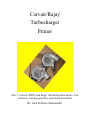
1
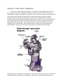
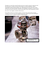
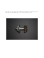
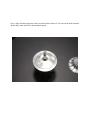
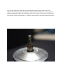
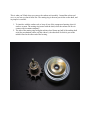
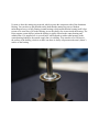
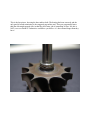
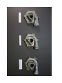
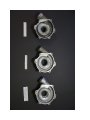
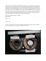
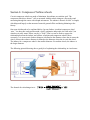
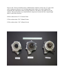
Corvair/Rajay Turbocharger Primer Part 1: Corvair (TRW) and Rajay 300-Series turbo basics, a bit of history, housing specifics, and wheel sizes/trims By: Nick Williams (Miniman82) Index Section 1: My Story Page: 4 Section 2: Some background on our Page: 6 Turbochargers Section 3: Turbo Basics: Operation Page: 8 Section 4: Parts of a Rajay Turbo Page: 11 Section 5: Compressor/Turbine Page: 18 Page: 21 Housings Section 6: Compressor/Turbine Wheels DISCLAIMER! First and foremost, I am not a turbocharger technician. I am not ‘qualified’ per se to work on these things, and much of what I have learned has been through actual hands-on experience with these units, what I have read in various technical manuals and via telephone conversations with those who are qualified in the industry. None of the information contained herein shall be used in conjunction with any sort of aviation maintenance, and I am not liable for any damages you may experience by following my advice. This is only a basic guide, for the layperson. This primer should be used to gain insight as to how these units operate, how they are built, and how to service them with respect to automotive applications from my point of view. That said, there is some good information here. I haven’t found this collection of information anywhere else, so soak it up and use it for your enjoyment. -Nick Section 1: My story Though I have owned many turbocharged vehicles, the Corvair was my first experience with the TRW/Rajay unit. A few of the other turbo rides I have owned include a 1989 Volvo 480 Turbo (Garrett T2), a 1989 Ford Sierra Cosworth (Garrett T3), and my 1958 VW Beetle 1915cc (Garrett T3) with Megasquirt fuel injection kit and distributorless ignition. My first Corvair is a 1966 164ci Corsa model I bought for $3500 from a Home Depot parking lot, equipped with a 2-barrel down draft Weber progressive carburetor, and a stock turbocharger. The previous owner hadn’t taken the time to tune the Weber correctly, so the car didn’t run very well. It started and ran, but didn’t build any boost and pinged pretty bad at high speed. Based on my previous experience, I pegged the turbo as the guilty party responsible for all the issues. Sure enough, upon inspection the compressor wasn’t moving. I removed the unit, disassembled it, and gave it a good cleaning. There was a ton of coked up carbon behind the heat shield due to a leaking turbine seal, which is typical of these units. After being cleaned and reassembled, the turbo was once again free to spin but the car still didn’t work right. As it happens the Weber was too far out of whack for me to try jetting, but fortunately the stock single side draft Carter YH was still in the trunk. After going through it to make sure all the parts were there, I put it on the car and it worked! According to the PO, it was leaking so they swapped to the Weber to get it back on the road. Once the YH was on the car it was much more enjoyable to drive, though it was running a little too rich for my liking. Even so, I was now able to drive it like I wanted to. Only thing that was still giving me fits was the ignition system- it still pinged under boost. I had tried to get the stock distributor to work several times, but after spending good money on 2 different pressure retard units, buying a Pertronics and hot coil, and multiple base timing settings, I decided to throw in the towel and went to something infinitely better: Megajolt/Ford EDIS distributorless programmable ignition, thanks to Autosport Labs. At that same time, the engine started making some strange noises which I attributed to a rod bearing. So, out the engine came for a rebuild and Megajolt conversion. As it happens, there was nothing wrong with the engine bearings: it was the flywheel rattling away! This is common knowledge to seasoned Corvair owners, but at that time I had no idea of the flywheels riveted construction. By the time I found out, it was already too late and the engine was on the ground. I figured I might as well rebuild it anyway at that point, since I would be trusting it for DD duty. Long story short, after the distributorless conversion (which can be found elsewhere on the internet) and rebuild, all my problems besides the rich carburetor jetting had been cured. I also added a large external oil cooler from a Ford Super Duty with thermostatically controlled electric fan, to keep oil temperatures in check for the days when I really felt like beating on it. Now the car was on daily driver status, and was very enjoyable. I used it for the next 3 years with absolute dependability, though the extreme heat of the California San Joaquin Valley was at times hard on the engine due to my harsh driving habits. Once I moved to Chicago in late 2008 however, there was no such bad weather to deal with. The cold weather made it possible to drive the car flat out literally all of the time- and that’s exactly what I did. The thing was an absolute blast, hitting almost 10 PSI through every gear except first. As I’m sure most turbo Corvair owners will attest to, this is by far the most fun car on the freeway I’ve ever owned. The Cosworth was a spotlight racer no doubt, but even that famous car had nothing on the 50-100 MPH sprints the turbocharged Corvair is capable of. But of course even that wasn’t enough, and soon I was looking for more. I would get my chance to make additional upgrades, as the windshield sprung a leak and starting letting water inside the car whenever it rained: the seal was shot, the frame was rusty, and it was bodywork time. I don’t do bodywork. Period. The car had served me well for the last few years, so I made the decision to have it restored to former glory. That being the case, I hired TLC Restorations to redo the shell while I did my thing with the engine. Again the turbo came off, this time for an E-Flow compressor upgrade and Crown turbine housing. Also on the menu is a Weber 45 DCOE side draft carburetor, Audi wastegate, possibly a water-air intercooler, and digital boost controller. Things will be getting faster at a geometric rate very soon, I can tell you that much. That’s pretty much where I’m at right now: car is in the shop, and I’m spending the winter of 2009 building a new turbo and writing guides. Section 2: Some background on our turbochargers As soon as I began looking for parts to upgrade the compressor on my turbocharger, it became very obvious that I was up against everyone’s mortal enemy: time. No one had parts for these units, and I found out after making a few phone calls that the parts were no longer being produced so the only option was spares. I ended up finding a place in Illinois that sold me the compressor wheel and cover (Area Diesel), so I was good to go. But curiosity had gotten the best of me, and soon I was making more phone calls, doing internet searches and asking around for any information people might have as to what had happened to the Rajay company, and the reason why spares were so scarce. The following is what I’ve found. The farthest back I am able to trace the lineage of the Corvair’s turbocharger, is the company that originally produced it for Chevrolet: TRW. TRW (Thompson Ramo Wooldridge Inc.) was founded in 1901, and was involved in a number of businesses, mostly defense-related, but including automotive, aerospace and credit reporting. I found a helpful article on the internet, which explains what happened with the TRW company, and the production rights for their turbocharger over the years. http://www.kellyaerospace.com/articles/KA_Turbocharger.pdf A brief history of the five manufacturers who have owned the RAJAY turbocharger line: 1958 — TRW (Thompson-Ramo-Wooldridge of Cleveland, OH) develops the 300 Series Turbocharger. 1969 —RAJAY Industries (Long Beach, CA.), a unit of the Texstar Corp. in Grand Prairie, TX, acquires the entire TRW Turbocharger line. Texstar later became a unit of the Hillman Co. of Pittsburgh, PA. 1982 — Roto-Master Inc. (North Hollywood, CA), later a unit of Echlin Corp. (Branford, CT) acquires the entire RAJAY Industries operation from Hillman Co., including the RAJAY STC’s for aircraft kits. 1986 — AiResearch Industrial Division of the Garrett Corporation, now AlliedSignal Automotive, acquires the entire operation of Roto-Master from Echlin Corporation and relocates it to the Garrett turbocharger facilities in Torrance, CA. 1995 — RAJAY turbocharger STCs were divested of to Kelly Aerospace, Inc. in Montgomery, AL. 1997 — Kelly Aerospace Power Systems (Montgomery, AL.), announces in August its purchase of the RAJAY turbocharger line from AlliedSignal. This purchase includes manufacturing, engineering, and design rights to both aircraft and automotive turbochargers. You can see the lineage has been a tenuous one over the years, changing hands more than a few times. The most recent transaction was the sale of KTR (Kelly Turbine Rotables) to First Aviation Services in late 2009, who still operate KTR under the same name. Since the current production of parts is exclusively to the Aviation community, new part prices have skyrocketed in recent years. Therefore, the best way to get spare parts and rebuild kits remains end users with spares, and auction sites on the internet. Occasionally you can find good deals out there, but they are few and far between. My policy lately has been to snap up any reasonably priced spare parts I come across, since I don’t know when the next deal will come. It’s actually more akin to my vintage electronics collecting than anything else, since it’s a small quest sometimes to find what you’re looking for. I’ve also heard that the Rajay name was sold to Turbonetics, but that info is tough to find. Anyone having details should contact me, so I can make updates to this document. The Aviation sector uses Rajay turbochargers because they are very rugged. Their bearing structure and rotating parts are much sturdier than other turbochargers, so they make a good choice when heavy duty applications are on the table. Most automotive engine builders and tuners write them off, because they are an outdated technology. They are correct in a sense, being that low drag ball bearing units have become a staple in high performance (read: high priced) applications. But the old technology still has many advantages these days besides the price: namely, user serviceability. The rotating parts of most other turbochargers are balanced on high-speed VSR machines as a turbine/compressor unit. This means that once they become separated, they must be balanced again to retain adequate service life from vibration induced destruction of the turbo journal bearings. I won’t even get into servicing a ball bearing turbo; suffice it to say you’ll need your loan officer present. With Rajay turbochargers, this is not the case. Every single technician I have spoken to has told me that the Rajay rotating parts are balanced individually, so any compressor wheel may be readily mated with any turbine shaft without the requirement for a high-speed VSR balance job upon reassembly. What this means is that given the correct service manual (as GM gave all turbo Corvair owners within the factory chassis manual), it’s possible for nearly anyone with the correct tools to rebuild these units. There is even a ‘turbo supplement’, to help with additional facts. Also of note, is that all 300-Series turbochargers come with a positive (carbon) seal assembly. This means they can be used in draw through configuration, with the carburetor before the turbo, without additional modifications. Other units may require this type of seal to be retrofitted at additional cost before using them in a draw through application, adding to the appeal of the 300Series turbocharger in these types of applications. The carbon seal assembly prevents oil from being drawn into the intake stream via engine vacuum during operation, since with draw through configuration the throttle plate is before the turbo compressor which causes the entire compressor to be under engine vacuum much of the time. The other type of seal used is the dynamic (or piston ring) seal, which is identical to the seal found at the turbine end of 300-Series turbochargers. It’s simply a gapped metal ring seal, so it can’t keep oil out of the compressor during vacuum situations. The result of using a turbo with dynamic compressor seal in draw through configuration will almost assuredly be a gigantic smoke screen behind your car, as oil drawn in will be burned in the engine. Section 3: Turbo basics: Operation Before you can get inside a turbocharger it’s important to understand its function, and how exactly they go about doing their job. When you break it down to its most basic form, a turbocharger is simply a centrifugal air compressor. How it is driven is what sets it apart from all other viable types of automotive compressors: it extracts the energy it needs to compress incoming air by introducing a turbine into the exhaust stream, which converts the exhaust pressure and flow into a rotating mechanical motion to turn a shaft. There is a compressor wheel at the opposite end of this shaft so when the turbine spins, so does the compressor. Therefore, energy taken from the otherwise wasted exhaust stream is used by the turbine to power the compressor via a common shaft. The compressor spins at a high rate of speed (upwards of 100,000 RPM), sucking in air at the inlet, compressing it and expelling into the engine. During operation on an engine, a percentage of every pulse of exhaust gas energy is converted to rotational motion, transferred to the compressor wheel via the common shaft, and the entire assembly begins to rotate and pick up speed. Once sufficient energy is being extracted from the exhaust, the compressor wheel will reach a speed which will begin to impart a positive pressure on the intake tract. This is called boost pressure, or colloquially, ‘boost’. Boost pressure is defined as any increase above atmospheric pressure produced inside the intake manifold of an engine by a supercharger. It is commonly measured in PSI, inches of mercury (inHg), or bar. Standard atmospheric pressure is 14.7 PSI absolute, which means that the air all around us at this very moment is already at 14.7 PSI. This means that (for the purposes of this primer) the intake pressure of a naturally aspirated engine at wide open throttle is 14.7 PSI. This can be confusing, since most gauges read ‘0’ when a naturally aspirated engine is running at wide open throttle. This illustrates the difference between absolute pressure, and gauge pressure. Because our atmosphere is already at 14.7 PSI, gauge manufactures reference atmospheric pressure as ‘0’ to make it easy to visually see when the engine is being operated in an intake vacuum, and when it’s being operated under intake pressure relative to the pressure around you and I. In other words it’s done for clarity reasons, to make the gauge easier to read at a glance. OK, fine. Now we understand how to create a pressure in the intake manifold, using spent exhaust gasses to power the whole show. However without some form of control, the whole thing would quickly run away (i.e., the compressor would keep spinning faster and faster) causing destruction of the turbocharger, engine, or both. The way a stock Corvair limits boost pressure is a restrictor plate design, which takes the form of the carburetor throat. By having a carefully sized restriction on the inlet of the turbocharger’s compressor, you effectively limit the amount of air it can ingest, thereby placing a limit on the amount of boost pressure the turbo can produce. This is why the sizing of the venturi on a turbo Corvair is so important, because without that restriction the boost pressure would quickly get too high causing engine damage. This is why when you install a larger carburetor on a turbocharged Corvair, you need some other form of boost control. That form of control is usually a wastegate, but can be a fixed size orifice. A wastegate is a pneumatically controlled valve, installed in the exhaust system, which routes exhaust away from the turbocharger turbine on demand. They can be internal (part of the turbo), or external. When less exhaust is available to the turbine, it loses speed and boost pressure falls. Wastegates are most often actuated by the boost pressure created by the turbo compressor itself, hence the system is simple in operation. Boost pressure acts upon a diaphragm, which is mechanically connected to the wastegate valve. When pressure rises, the valve opens to route exhaust flow away from the turbine. Wastegates can be dumped to atmosphere, or routed back to the exhaust system after the turbine, but prior to the muffler. They can be controlled by a manual bleed valve, or by digitally controlled solenoid valves. Rajay turbos do not have an internal wastegate, so if one is to be used it must be mounted externally. On a Corvair, they are normally mounted to the exhaust crossover tube and dumped to atmosphere. Here is a picture of a generic, external wastegate. GENERIC! Section 4: Parts of a Rajay turbo Here are the internal parts of a Rajay turbo, laid out in order of assembly so you can see them. (Just in case you can’t see the paper labels I made) From top left, to bottom right: Compressor housing, left threaded nut, special washer, compressor wheel, shim, carbon seal assembly, o-ring, mating ring, bearing, bearing shim, CHRA, turbine piston ring seal, turbine (shaft), and finally the turbine housing. Not pictured are the compressor housing gasket, and turbine housing gasket. They are black in color, so they wouldn’t show up well in this shot anyway. Also absent from this shot are the snap rings which retain the bearing and carbon seal. Some versions of turbo do not have the snap rings, so I left those out. Same thing with the heat shield; there are differences with those as well, but I’ll get into the generational particulars next edition. One thing worth mentioning is that the special nut and its washer have been superseded by a different nut, which doesn’t require a washer under it (the bottom is flat). The original nut is a nylock type, and should not be reused according to some (I’m sure many people reuse it anyway). The new style nut is partially smushed on one axis, so the tension on the threads provides the self locking ability. Ancillary parts of the turbocharger may include oil feed and drain lines, intake and exhaust tubing, filter assemblies, and various engine vents, fittings and hoses. Next, a shot of the rotating parts fully assembled; shown outside the center housing, so you can see how they fit together. Following is a series, showing how they fit together. Next, a shot with the compressor wheel, nut and washer removed. You can see the shim centered on the shaft, under which lies the aluminum spacer. Here, I have removed the shim and moved the aluminum spacer up the shaft a little. This illustrates that the spacer passes through the carbon seal, but does not touch it. It rests upon the mating ring under the carbon seal, so that the shaft is free to rotate. The purpose of the shim is to fine tune the position of the impeller, to facilitate setting wheel-to-compressor housing clearance. This is what you’ll find when you remove the carbon seal assembly. I turned the carbon seal over, so you can see what it looks like. The mating ring is the next part in line on the shaft, and its purpose is twofold: 1. To interface with the carbon seal, to keep oil out of the compressor housing when it’s under a vacuum. The mating ring rotates with the shaft, while the carbon seal face in contact with it remains stationary. 2. The side of the mating ring facing the turbine wheel forms one half of the turbine shaft axial play mechanism (others call this ‘thrust’), the other half of which is part of the turbine wheel at the other end of the bearing. Up next we have the mating ring removed, which exposes the compressor side of the aluminum bearing. You can also see the shoulder on the shaft that the mating ring sits on. Modern turbochargers have wet fully floating journal bearings, which means that the bearing itself is free to turn on its own film of oil in the housing, just as the shaft is free to turn inside the bearing. The Rajay support system differs, in that the bearing is rigidly affixed to the center housing and cannot rotate. It is supplied oil via several holes, which match up with a radial passage in the center housing leading to the outside supply line via a drilling. You can also see a few lines in the surface of the bearing, which is to make sure there is always oil present at the axial (‘thrust’) surface of the bearing. This is the last picture, showing the bare turbine shaft. The bearing has been removed, and the only part left worth mentioning is the staggered gap turbine seal. These are purportedly better than the old straight gapped ones, in that they do a better job of controlling oil loss. No, this is NOT a new revelation as Turbonetics would have you believe- it’s been around longer than they have! Section 5: Compressor/Turbine Housings I’m just going to briefly go over compressor and turbine housings, since there isn’t much to know about them other than the size of the bore in them for the compressor or turbine wheel. The compressor housing (sometimes referred to as a cover) is machined from cast aluminum, and the turbine housing is made of cast iron. They come in 3 sizes: B, F, and E. The compressor cover is bolted to the center housing by 6 bolts, and is located by 2 steel dowel pins. The dowel pins ensure correct alignment with the compressor wheel, so they do not come into contact with each other. The turbine housing mounts centric with the center housing located by a recess, and is held in place by a steel v-band clamp. Corvair compressor covers have a triangular mounting pad for the carburetor, where non-Corvair covers usually have a simple round inlet for attaching intake tubes. There is a threaded hole in the Corvair cover for a fitting with a fixed orifice, which forms part of the positive crankcase ventilation system. The turbine housings can have the Corvair style 3-stud outlet (which takes either a flat gasket or packing depending on model year), or a round 4-stud outlet. All Rajay 300-Series turbos have the same inlet flange as a Garrett T-4 turbo, so finding turbine inlet gaskets is a piece of cake. On the next 2 pages are photos of the front and back of the 3 sizes of compressor cover. The EFlow cover was machined by your truly in a lathe and by hand, from a used F-Flow cover. It’s not a very tough process, just tedious. I started by enlarging the bore, taking .005” cuts at a time until the compressor wheel fit. Then I worked the radius to fit the curves of the wheel, using a combination of lathe and hand work. This must be done progressively, until the wheel will go all the way into the housing. After the wheel fit correctly, I added an angled transition from the small F-Flow intake size to the new, larger E-Flow. Not sure if it’s going to make a difference or not, but I figured a smooth transition would help airflow through the inlet. The inlet I.D. of the covers are as follows: (approximate) B-Flow: 1.62” F-Flow: 1.84” E-Flow: 2.25” I only have a B-Flow and F-Flow turbine housing right now, but it still illustrates the difference in bore sizing. The housings for all the wheel sizes are essentially the same, the only thing that changes is the bore via machining. You can see that a B-Flow 150 HP turbine has a large step in it, the F-Flow 180 HP turbine only has a little step, and an E housing does not have a step in it at all. I suspect this was a cost cutting measure, because it allows any housing to be used with any wheel after a simple cutting operation which could be done on a lathe. I assume they all started as B-Flow housings, being opened up to take larger wheels as required. I am unsure about the A/R of these housings, so if anyone knows I’d love to hear about it. The bore of turbine housings is as follows: (approximate) B-Flow: 2.13” F-Flow: 2.37” E-Flow: I don’t have one to measure, but judging by the dimensions of the wheel it’s probably somewhere around 2.54” give or take a few fractions of an inch. Section 6: Compressor/Turbine wheels Corvair compressor wheels are made of aluminum, the turbines are stainless steel. The compressor wheels are about 1” tall, as measured with the wheel sitting on a flat surface and measuring through the center with a depth micrometer. The turbine is about 4.60-4.80” in length, which depends largely on the amount of material ground off the end during balancing at the factory. One term which needs to be explained before I go any farther, is turbine/compressor wheel ‘trim.’ You hear this word tossed around a lot by companies and people who ‘talk turbo’, but what does it really mean? What, exactly, is 'Trim?' Trim is a term to used to express the relationship between the inducer and exducer of turbine and compressor wheels. More accurately, it is an area ratio. Inducer diameter is defined as the diameter where the air enters the wheel, whereas the exducer diameter is defined as the diameter where the air exits the wheel. The inducer for a compressor wheel is the smaller diameter. For turbine wheels, the inducer is the larger diameter. The following pictorial drawing does a good job of explaining the relationship, in visual terms. The formula for calculating trim is: Here are the 3 flavors of compressor wheel, and their dimensions. They all have the same exducer size (3”, or 76mm), so I will only list approximate inducer size and calculated trim for each. B-Flow inducer/trim: 1.60” (41mm)/29 trim F-Flow inducer/trim: 1.83” (46mm)/37 trim E-Flow inducer/trim: 2.25” (57mm)/56 trim Here are the 3 flavors of turbine wheel, with dimensions. Inducers are the same (3” again, same as the compressor exducers), so I’m listing approximate exducer size and calculated trim. Remember that with turbine wheels, the larger diameter is the inducer, the smaller size is the exducer. They are the other way around from the compressor, because the flow of gas through them is in the other direction. B-Flow exducer/trim: 2.0” (51mm)/45 trim F-Flow exducer/trim: 2.30” (58mm)/58 trim E-Flow exducer/trim: 2.44” (62mm)/66 trim Lastly, I hope this comes to good use for everyone who picks it up. It’s taken me quite a bit of time to get this all together, and I know I’ll use this as a reference all the time. Since I have CRS real bad, it’s important to me to write things like this down. That means if you’re anything like me, you have CRS, and also like Rajay turbos, this will be just about indispensable! Have fun, and be safe! Nick Williams