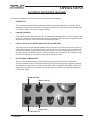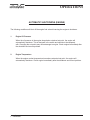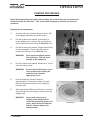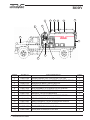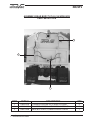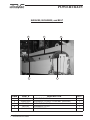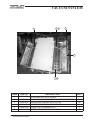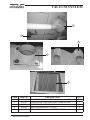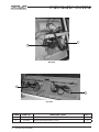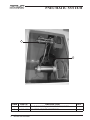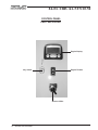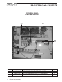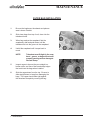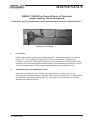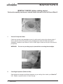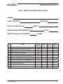
1
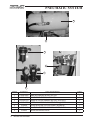
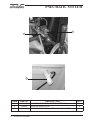
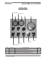
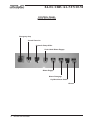
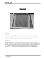
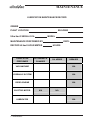
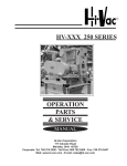
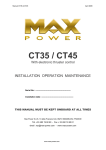
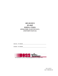
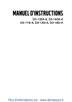
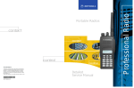
T-475 SERIES
A DIVISION OF Hi-Vac® CORPORATION
Ultra-Vac® SERIAL NUMBER : UV-XXXX
OPERATION
SERVICE
& PARTS
M A N U A L
A Product of Hi-Vac Corporation • 117 Industry Road • Marietta, Ohio 45750 USA
Corporate: Tel: 740.374.2306 • Toll Free USA: 800.752.2400 • Fax: 740.374.5447 • Web: www.hi-vac.com • E-mail: [email protected]
Aquatech Direct: Tel: 740.374.9171 • Toll Free USA: 800.800.1016 • Fax: 740.374.5447 • Web: www.aquatechinc.com • E-mail: [email protected]
®
A DIVISION OF Hi-Vac CORPORATION
®
TABLE OF CONTENTS
Warranty information for your new Ultra-Vac® Unit
Message to new owner
SECTION 1: SAFETY PRECAUTIONS
General precautions and warnings
PLEASE READ!!!
SAFETY FIRST!!!
SECTION 2: OPERATIONS
Prestart procedures
StarT-up PROCEDURES
MANUAL Shutdown PROCEDURES
AUTOMATIC SHUTDOWNS (MACHINE)
AUTOMATIC SHUTDOWNS (ENGINE)
DUMPING PROCEDURES
SECTION 3: MACHINE SPECIFICATIONS
BODY
POWERTRAIN
HYDRAULIC SYSTEM
VACUUM SYSTEM
PNEUMATIC SYSTEM
ELECTRICAL SYSTEM
SPARE PARTS LIST
T475 LOGIC - P&I DIAGRAM
SECTION 4: MAINTENANCE
POWER TAKE-OFF
Filter bag REMOVAL & INSTALLATION
HEPA FILTER
Tensioning v-belt drives
Adjusting the Level probe
LUBRICATION INTERVALS
recommended lubricants
lubrication MAINTENANCE record form
DAILY CHECKS
WEEKLY CHECKS
MONTHLY CHECKS
MAINTENANCE RECORD FORMS
bill of materials
ULTRA-VAC® OPERATIONS, PARTS, & SERVICE MANUAL
1
®
A DIVISION OF Hi-Vac CORPORATION
®
SECTION 5: OPTIONS
AS LISTED
SECTION 6: ELECTRICAL
ELECTRICAL SCHEMATIC
SECTION 7: ACCESSORIES
ACCESSORIES
SECTION 7: MANUFACTURERS MANUALS
JOHN DEERE ENGINE (located in seperate manual)
TWIN DISC PTO (located in seperate manual)
ROOTS BLOWER
DREXELBROOK LEVEL PROBE
LEESON MOTOR
ASCO SOLENOID VALVE
MAC SOLENOID VALVE
ALLENAIR SOLENOID VALVE
GRESEN VALVE
KUNKLE RELIEF VALVE
KEYSTONE VALVE
GOYEN TIMER BOARD
DWYER PRESSURE GAUGE
MARSH PRESSURE GAUGE
SPAN GAUGE
WATTS AIR FILTER
PARKER REGULATOR
PARKER LUBRICATOR
ZINGA FILTER HEAD & FILTER
BARKSDALE PRESSURE SWITCH
UNITED ELECTRIC TEMP CONTROL
STEMCO MOISTURE EJECTOR
GLOBAL VIBRATOR
CONDUCTIX GROUND REEL
FLANDERS HEPA FILTER
ULTRA-VAC® OPERATIONS, PARTS, & SERVICE MANUAL
2
®
A DIVISION OF Hi-Vac CORPORATION
®
INSPECTION PROCEDURES
All pieces received should be inspected for damage immediately upon receipt.
1.
Damage can be most easily detected by looking for scrapes on the paint.
2.
Inspect all sheet metal and structural steel for damage such as bends, kinks or breaks.
3.
Check all wiring for abrasions, cuts, cracks, etc. If any are found, repair or replace before connecting to power source.
Check all conduit runs and fittings for defects.
4.
5.
Check motor and vacuum pump for free rotation before starting under power for the first time after installation.
6.
Compare the packing list attached to each piece of each shipment.
7.
Verify the number of pieces and description of each piece shown on the packing slip.
REPORT ANY DAMAGE, NO MATTER HOW SLIGHT, IMMEDIATELY TO:
Hi-Vac® Corporation
117 Industry Road
Marietta, OH 45750
Attention: Service Department
Phone: 740.374.2306
Toll Free: 800.752.2400
Fax: 740.374.5447
ULTRA-VAC® OPERATIONS, PARTS, & SERVICE MANUAL
3
®
A DIVISION OF Hi-Vac CORPORATION
®
WARRANTY
Hi-Vac® CORPORATION WARRANTS TO THE ORIGINAL PURCHASER OF THE Ultra-Vac® UNIT QUOTED
HEREIN THAT THE Ultra-Vac® UNIT SHALL BE FREE FROM DEFECTS IN MATERIAL AND WORKMANSHIP UNDER NORMAL USE AND SERVICE. Hi-Vac® CORPORATION DOES NOT WARRANT
COMMERCIAL ITEMS MANUFACTURED BY OTHERS SUCH AS DIESEL ENGINES, TRUCK CHASSIS,
TIRES OR MOTORS. Hi-Vac® CORPORATION’S OBLIGATION UNDER THIS WARRANTY SHALL BE LIMITED TO THE REPAIR OR EXCHANGE OF ANY PART OR PARTS WHICH MAY PROVE DEFECTIVE
UNDER NORMAL USE AND SERVICE WITHIN THE SHORTER PERIOD OF TWO (2) YEARS OR FOUR
THOUSAND (4,000) WORK HOURS FROM THE DATE OF DELIVERY TO THE ORIGINAL PURCHASER
AND WHICH Hi-Vac® CORPORATION’S EXAMINATION SHALL DISCLOSE TO ITS SATISFACTION TO BE
DEFECTIVE. THIS WARRANTY REQUIRES PURCHASER TO OPERATE THE Ultra-Vac® UNIT IN STRICT
COMPLIANCE WITH THE PRINTED INSTRUCTIONS AND TO SERVICE THE Ultra-Vac® UNIT
ACCORDING TO THE METHODS AND SCHEDULES CONTAINED IN THE Ultra-Vac® UNIT’S MANUAL.
EVIDENCE OF PURCHASER’S SCHEDULED MAINTENANCE MUST BE REPORTED IN WRITING TO
Hi-Vac® CORPORATION ON THE FORMS SUPPLIED TO PURCHASER IN THE Ultra-Vac® MAINTENANCE
MANUAL. SHOULD PURCHASER BELIEVE A DEFECT HAS BEEN DISCOVERED, THE PURCHASER
SHALL RETURN THE ALLEGED DEFECTIVE PART TO Hi-Vac® CORPORATION FOR EXAMINATION, F.O.B
THE Hi-Vac® PLANT, MARIETTA, OHIO. IN THE EVENT PURCHASER DOES NOT SERVICE AND MAINTAIN
THE Ultra-Vac® UNIT ACCORDING TO THE Ultra-Vac® MAINTENANCE MANUAL, THE WARRANTY IS TO
BE CONSIDERED NULL AND VOID AND Hi-Vac® CORPORATION’S OBLIGATION HEREUNDER SHALL BE
DEEMED FULFILLED. THIS WARRANTY IS EXPRESSLY IN LIEU OF ALL OTHER WARRANTIES EXPRESSED OR IMPLIED,
INCLUDING THE WARRANTIES OF MERCHANTABILITY AND FITNESS FOR USE AND OTHER OBLIGATIONS OR LIABILITIES ON THE PART OF Hi-Vac® CORPORATION.
LIMITS OF LIABILITY
Hi-Vac® CORPORATION SHALL NOT BE LIABLE FOR AND PURCHASER ASSUMES RESPONSIBILITY FOR
ALL PERSONAL INJURY AND PROPERTY DAMAGE RESULTING FROM THE HANDLING, POSSESSION
OR USE OF YOUR Ultra-Vac® INDUSTRIAL VACUUM LOADER BY THE PURCHASER. THE LIABILITY OF
Hi-Vac® CORPORATION ARISING OUT OF THE SUPPLYING OF YOUR Ultra-Vac® INDUSTRIAL VACUUM
LOADER, OR ITS USE WHETHER ON WARRANTIES OR CLAIM OF NEGLIGENCE OR OTHERWISE,
SHALL NOT IN ANY CASE EXCEED THE COST OF CORRECTING DEFECTS IN YOUR Ultra-Vac® INDUSTRIAL VACUUM LOADER AS HEREIN PROVIDED. Hi-Vac® CORPORATION SHALL NOT IN
ANY EVENT BE LIABLE FOR ANY LABOR EXPENDED BY THE PURCHASER ON ANY PART OR PARTS
OR FOR ANY SPECIAL DIRECT OR INDIRECT OR CONSEQUENTIAL DAMAGES. NO MATERIAL MAY
BE RETURNED WITHOUT FIRST GETTING APPROVAL FROM Hi-Vac® CORPORATION. ANY GOODS
RETURNED WITH SUCH APPROVAL MUST BE SENT BACK WITH ALL TRANSPORTATION CHARGES
PREPAID WITHIN 30 DAYS AFTER ISSUANCE OF APPROVAL. GOODS RETURNED AND ACCEPTED IN
ACCORDANCE E PRICES PAID AT TIME OF SHIPMENT.
ULTRA-VAC® OPERATIONS, PARTS, & SERVICE MANUAL
4
®
A DIVISION OF Hi-Vac® CORPORATION
MESSAGE TO NEW OWNER
Congratulations on your purchase of a new Ultra-Vac® Vacuum
Loader. This manual is supplied for your convenience to
assist you in adequately maintaining, servicing and operating your
Ultra-Vac® Vacuum Loader.
Your Ultra-Vac® Vacuum Loader has been designed to give you
many years of dependable, trouble free service, which can be
attained only through conscientious care by your personnel.
Therefore, cooperation, practice and skill on the part of all
personnel associated with your Ultra-Vac® is necessary to
maintain maximum productivity.
The material in this manual has been carefully and thoughtfully
prepared to provide a simple and understandable guide. It should
be carefully read and thoroughly understood by all personnel
responsible for your Ultra-Vac® before engaging in both
operation and the maintenance of the system.
The very best wishes from our entire organization are extended to
you with the assurance that you will enjoy long and dependable
service from this Ultra-Vac®.
ULTRA-VAC® OPERATIONS, PARTS, & SERVICE MANUAL
5
®
A DIVISION OF Hi-Vac® CORPORATION
SAFETY
PRECAUTIONS
ULTRA-VAC® OPERATIONS, PARTS, & SERVICE MANUAL
®
A DIVISION OF Hi-Vac CORPORATION
®
CAUTION!
SOME DO’S AND DON’TS BEFORE GETTING STARTED WITH YOUR NEW
Ultra-Vac® SYSTEM.
The safety of the operator is of great importance to us at Hi-Vac® Corporation. The decals, shields,
guards and other protective features that are designed into the machine are there for your protection.
A high percentage of the accidents that occur are due to careless behavior or misuse of machinery. We
ask you to be a careful operator and to properly service your machine.
ULTRA-VAC® OPERATIONS, PARTS, & SERVICE MANUAL
1
®
A DIVISION OF Hi-Vac® CORPORATION
PROCEED WITH CAUTION!
Before attempting to operate the machine, read carefully and understand all instructions contained in the
manual.
IT IS VERY IMPORTANT THAT YOU UNDERSTAND THE FOLLOWING SAFETY WARNINGS IN FULL. INJURY
OR DEATH TO PERSONNEL, AND/OR DAMAGE TO MACHINE CAN RESULT.
*
Unit should only be operated by thoroughly trained personnel
*
Do not put your face or any portion of head in front of the nozzle.
*
Hearing protection must be worn by operator and those working near the vacuum loader.
*
Do not operate machinery without proper guards in place. Keep away from moving objects
*
Do not put your hand in front of the intake nozzle while in operation.
*
Do not put your face or any portion of head in front of the nozzle.
*
Do not vacuum any flammable liquid.
*
Check that unit is properly stopped so unit will not tip or roll.
*
Do not lubricate, adjust or repair the Ultra-Vac® unit unless engine is shut down.
*
NEVER raise body unless the tailgate is fully open.
*
NEVER operate tailgate while body is in elevated position.
*
NEVER move the Ultra-Vac® with the body in the raised position.
*
Clear the area behind the Ultra-Vac® of all personnel before opening or closing the tailgate.
*
Never inspect or work under the raised body without the safety body prop in place.
*
NEVER inspect or work under the open tailgate without a tailgate prop in place.
*
Do not operate the Ultra-Vac® unit while wearing loose clothing, watches or rings.
*
Periodically check for any loose bolts or set screws.
NOTE: AS WITH ANY TYPE OF HEAVY DUTY EQUIPMENT, CAUTION MUST BE EXERCISED IN ITS PROPER USE.
WARNING:
FAILURE TO COMPLY WITH ANY OF THE ABOVE SAFETY NSTRUCTIONS OR THOSE THAT FOLLOW WITHIN THIS MANUAL MAY RESULT IN SEVERE INJURY OR DEATH!
PLEASE REMEMBER:
Safe operation begins with a safe operator. We ask you to be that type of operator.
ULTRA-VAC® OPERATIONS, PARTS, & SERVICE MANUAL
2
®
A DIVISION OF Hi-Vac® CORPORATION
OPERATIONS
ULTRA-VAC® OPERATIONS, PARTS, & SERVICE MANUAL
OPERATIONS ®
A DIVISION OF Hi-Vac CORPORATION
®
PRESTART PROCEDURES
Caution:
Before prestarting your Ultra-vac® unit, be sure you have read and understood all of the safety warnings and precautions located in the “Safety Precaution” section of this manual!
1.
Stop unit and be sure to set parking brake.
2.
Visually inspect the unit so that there are no obstuctions which may cause harm to machine or operating personnel.
3.
Check oil level in Vacuum Pump and Engine.
4.
Check coolant level in Engine.
5.
Check Hydraulic oil level and add if necessary.
6.
Check all Hydraulic hoses and fittings for leaks. Repair if necessary.
7.
Check belts for proper tension. (Refer to belt tensioning in this manual)
8.
Check that all doors are closed and locked and wet baghouse ball valves are closed.
9.
Attach vacuum loading hose.
10.
You are now ready to start your Ultra-Vac® unit.
ULTRA-VAC® OPERATIONS, PARTS, & SERVICE MANUAL
1
OPERATIONS
OPERATIONS ®
A DIVISION OF Hi-Vac CORPORATION
®
START-UP PROCEDURES
Before starting up your Ultra-Vac® unit, Be sure you have done all the “Prestart Procedures” located
on the previous page.
1.
At the control panel, turn key to start engine.
2.
With engine running, select which vacuum plenum to use. (i.e.. wet, dry left, dry right, or dry left and right).
3.
Press the “Fault Reset” button to clear “Hopper Full” condition alarm.
Note:
4.
This unit has been supplied with the new Drexelbrook “The Point Series” Level Probe. During initial start-up and after a loss of power, the operator must wait approx. 20
seconds to allow the probe to finish its calibration cycle. The blower will not start and the “Hopper Full” light will remain on until the cycle is complete and the blower “Fault Reset” button is pushed.
Allow Engine to idle until air pressure is built up before engaging Vacuum Pump.
WARNING:
The Vacuum System will not begin operation until air pressure is at least 60 psi.
5.
At engine idle speed, Push and hold the “Blower Engage” button for 5 seconds to fully engage the PTO. This will allow the Vacuum Pump to start. Be sure to engage and
disengage the blower at idle speed only.
WARNING:
6.
After Vacuum Pump is engaged, press up on the throttle control until you are at operating speed (2200 RPM’s).
7.
Once the unit is at operating speed, you may begin loading material. Periodically check gauges to ensure the unit is running properly.
8.
The Ultra-Vac® unit and engine have built-in shutdowns. If a shutdown occurs, immediately stop work and remedy the situation.
Never engage Blower above 1,000 RPM’s.
ULTRA-VAC® OPERATIONS, PARTS, & SERVICE MANUAL
2
OPERATIONS
OPERATIONS ®
A DIVISION OF Hi-Vac CORPORATION
®
MANUAL SHUTDOWN PROCEDURES
Before stopping unit, allow the Ultra-Vac® to run for a moment to let the lines clean out.
1.
Press down on the throttle control until you are at engine idle RPM’s.
WARNING:
2.
If time allows, let Vacuum Pump run at low RPM to cool down.
3.
Press the “Blower Disengage” button to stop Vacuum Pump.
4.
Turn key to stop engine.
Never disengage Blower above 1,000 RPM’s.
ULTRA-VAC® OPERATIONS, PARTS, & SERVICE MANUAL
3
OPERATIONS
OPERATIONS ®
A DIVISION OF Hi-Vac CORPORATION
®
AUTOMATIC SHUTDOWNS (MACHINE)
The following conditions will cause the blower to be automatically disengaged.
1.
HOPPER FULL
This is caused by material filling up inside the collector body and activating the Level Probe. This is indicated by a light on the control panel. Simply dump material out of the collector body and press the “Fault Reset” button. You may then continue loading.
2.
LOW AIR PRESSURE
If the Unit air pressure drops below 60 PSI, the blower will disengage and the “Low Air Pressure” light will turn on. Check all air lines for leaks and correct if necessary. When air pressure builds back up to above 60 PSI, push the “Fault Reset” button and restart the blower.
3.
LOW OIL LEVEL IN THE GEAR CASE(S) OF THE VACUUM PUMP
4.
HIGH BLOWER TEMPERATURE
There are low oil level float switches installed near the vacuum pump. Daily checks of the oil level, by visually inspecting the oil level sight glasses on the vacuum pump, will prevent a low oil condition. Do not use level switches to check oil level. In the event a loss of oil occurs during operation, the unit will shut down and the “BLOWER LOW OIL” indicator will light on the control panel. This condition is to be reset after the problem is corrected by pressing the “Fault Reset” button.
There is a high temperature sensing thermal switch and gauge located near the control panel. The thermal switch sensor is located in the discharge pipe of the vacuum pump. When the discharge air temperature reaches 350° F, the unit will shut down and the “BLOWER HIGH TEMP” indicator will light on the control panel. This condition is to be reset after the problem is corrected by pressing the “Fault Reset” button.
Blower Hi Temp
Blower Low Oil
Hopper Full
Low Air Pressure
ULTRA-VAC® OPERATIONS, PARTS, & SERVICE MANUAL
4
OPERATIONS
OPERATIONS ®
A DIVISION OF Hi-Vac CORPORATION
®
AUTOMATIC SHUTDOWNS (ENGINE)
The following conditions will shut off the engine fuel solenoid causing the engine to shutdown.
1.
Engine Oil Pressure
When the oil pressure in the engine drops below a desired set point, the engine will automatically shutdown. This is designed in the switch and should not be tampered with. Changing the set points may cause damage to engine. Check engine immediately after the shutdown and correct problem.
2.
Engine Temperature
When the engine coolant temperature rises above a desired set point, the engine will
automatically shutdown. Check engine immediately after the shutdown and correct problem.
ULTRA-VAC® OPERATIONS, PARTS, & SERVICE MANUAL
5
OPERATIONS
OPERATIONS ®
A DIVISION OF Hi-Vac CORPORATION
®
DUMPING PROCEDURES
Before dumping material out of the collector body, be sure that there are no personnel or
obstuctions near the Ultra-Vac®. This could result in damage to machinery or injury to
personnel.
Dumping Dry Compartments:
1.
At engine idle, turn Hydraulic Pump switch to “ON”. Only engage Hydraulic pump at Idle speed.
2.
Pull the Gresen valve marked “Lock/Unlock” to
unlock tailgate prior to raising. Be sure that there are no personnel at the back of the Ultra-Vac® unit.
3.
Pull the Gresen valve marked “Tailgate Open/Close” to open the tailgate. Be sure that there are no
personnel at the back of the Ultra-Vac® unit.
WARNING:
4.
Never open the tailgate without
first unlocking. This will cause damage to the equipment.
Pull the Gresen valve marked “Raise/Lower” to fully raise the collector body.
WARNING:
Be sure that the Ultra-Vac® is on a
level surface before raising the collector body. Possible
tipping may occur.
5.
Push and hold the “Vibrator” button for
approximately 3-5 seconds to loosen any stuck material. Repeat as required to fully empty the collector body.
6.
After inspecting the Blower Inlet Screen, Lower the collector body, close the tailgate, and then lock the tailgate locks.
WARNING:
Never work under body or
tailgate in the raised position unless the appropriate props are in place. Never move the Ultra-Vac® with the collector body in the raised position.
ULTRA-VAC® OPERATIONS, PARTS, & SERVICE MANUAL
6
OPERATIONS
Gresen Valve
Inlet Screen
OPERATIONS ®
A DIVISION OF Hi-Vac CORPORATION
®
DUMPING PROCEDURES (cont.)
Dumping Wet Compartments:
1.
With the collector body lowered, open the ball valves under the front of the collector body, on both sides, and drain the wet bag houses.
NOTE:
2.
Wet bag houses should be drained after each use.
The collector body must then be dumped as described in steps 1-6 on the previous page.
Ball Valve
NOTE:
3.
The collector body may also be emptied through the optional tailgate drain valve.
After material is unloaded, collector body
lowered, tailgate shut, and tailgate locked, you may then turn hydraulic pump to “OFF”.
Optional Tailgate Drain Valve
ULTRA-VAC® OPERATIONS, PARTS, & SERVICE MANUAL
7
OPERATIONS
®
A DIVISION OF Hi-Vac CORPORATION
®
MACHINE
SPECIFICATIONS
ULTRA-VAC® OPERATIONS, PARTS, & SERVICE MANUAL
BODY ®
A DIVISION OF Hi-Vac CORPORATION
®
3
5
4
12
13
6
2
1
11
7
9
10
ITEM
PART #
DESCRIPTION
QTY
1
2
3
4
U3201-0104
U4102-0621
U4201-0110
U1007-3669
ENGINE,JD4045,TIER 3,SP111P301 PTO,T475
PANEL,T475,12VDC W/INVERTER FOR DREXELBROOK
SILENCER,8”IN&OUT,VERTICAL,S716
ACCESS DOOR,NOSE,8x12,T475
5
U1007-3674
BOX ASSEMBLY,T475,W/HEPA FILTER IN NOSE
1
6
U1007-3162
INLET PIPE WELDMENT,T475,6”SCH.40
1
7
U1007-3372
TAILGATE,T475,95 3/4 WIDE BOX
1
8
U3904-0102
VALVE,HYD,4-WAY,3-SPOOL W/PRESSURE REL
1
9
U1012-0100
BELT GUARD,T475,JD4045,R715 RCSJ
1
10
U3907-0025
TANK,HYDRAULIC,10 GAL,HORIZONTAL NON-JIC
1
11
U5502-0103
CHASSIS,INTL,4300 SBA 4X2, T475
1
12
U1007-1856
DOOR,WET PLENUM,4 CUYD. BOX
2
13
U1007-2009
DOOR,DRY PLENUM,4 CUYD. BOX
2
ULTRA-VAC® OPERATIONS, PARTS, & SERVICE MANUAL
1
8
MACHINE SPECIFICATIONS
1
1
1
2
BODY ®
A DIVISION OF Hi-Vac CORPORATION
®
ASSEMBLY,REAR BODY,T475,95 3/4 WIDE BOX
PART #U1007-3376
1
2
3
ITEM
1
2
3
PART #
U3903-0035
U3903-0026
U4307-0008
CYLINDER,HYDR,DBL ACT,2”BORE,8”STROKE
CYLINDER,HYDR,DBL ACT,2”BORE X 5”STROKE
VALVE,BUTTERFLY,6”,HAND LEVER ACTUATOR
ULTRA-VAC® OPERATIONS, PARTS, & SERVICE MANUAL
2
MACHINE SPECIFICATIONS
DESCRIPTION
QTY
2
2
1
POWERTRAIN
®
A DIVISION OF Hi-Vac CORPORATION
®
ENGINE and PTO
PART # U3201-0104
Engine
PTO
**SEE JOHN DEERE ENGINE & TWIN DISC PTO MANUALS FOR DETAILS
ULTRA-VAC® OPERATIONS, PARTS, & SERVICE MANUAL
3
MACHINE SPECIFICATIONS
®
A DIVISION OF Hi-Vac® CORPORATION
POWERTRAIN BATTERY,12VDC,800CCA,350A RES. TOP POST
PART #U3312-0006
ULTRA-VAC® OPERATIONS, PARTS, & SERVICE MANUAL
4
MACHINE SPECIFICATIONS
POWERTRAIN ®
A DIVISION OF Hi-Vac CORPORATION
®
SHEAVES, BUSHINGS, and BELT
1
5
4
2
ITEM
PART #
2
4
U3403-0025
06-0163
06-0136
5
U3404-0139
1
3
06-0408
MACHINE SPECIFICATIONS
DESCRIPTION
SHEAVE,5V9.0 X 5-E
BUSHING,E X 2.25B X .63 SQ KEY (SPECIAL)
SHEAVE,5V8.5 X 5-E
BUSHING,E X 2.375
BELT,5R5VX850
ULTRA-VAC® OPERATIONS, PARTS, & SERVICE MANUAL
5
3
QTY
1
1
1
1
1
HYDRAULIC SYSTEM ®
A DIVISION OF Hi-Vac® CORPORATION
3
1
2
5
4
ITEM
PART #
DESCRIPTION
1
2
3
4
U3902-0069
U3914-0017
U3914-0021
U3907-0025
PUMP,HYD,CLUTCH,1.55 CU.IN.DISP,5.4GPM
FILTER,HYDRAULIC,CARTRIDGE
FILTER HEAD,HYD.SUCTION
TANK,HYDRAULIC,10 GAL,HORIZONTAL NON-JIC
5
U3904-0102
VALVE,HYD,4-WAY,3-SPOOL W/PRESSURE REL
ULTRA-VAC® OPERATIONS, PARTS, & SERVICE MANUAL
6
MACHINE SPECIFICATIONS
QTY
1
1
1
1
1
VACUUM SYSTEM ®
A DIVISION OF Hi-Vac CORPORATION
®
1
3
2
4
5
6
ITEM
PART #
1
U3701-0052
2
U3702-0024
3
U4623-0005
4
U3802-0015
5
U3802-0032
6
U3701-0053
MACHINE SPECIFICATIONS
DESCRIPTION
FILTER BAG,WET,4 CU YD BOX
CAGE,BAG,ALL 2 3/4”VENTURI W/4” RING SPACING
CHAIN,PSSG LINK #4/0 ZINC PLATED
GASKET,WET PLENUM DOOR,SE-475
GASKET,DRY PLENUM,SE-475
FILTER BAG,DRY,6”OD X 44” LONG
ULTRA-VAC® OPERATIONS, PARTS, & SERVICE MANUAL
7
2
QTY
8
40
12FT
2
2
32
VACUUM SYSTEM ®
A DIVISION OF Hi-Vac CORPORATION
®
2
1
3
ITEM
PART #
2
3
U4201-0110
27-0012
1
03-0399
DESCRIPTION
BLOWER,ROOTS,715RCSJ,LH,CCW,BOTTOM DISCH
SILENCER,8”IN&OUT,VERTICAL,S716
SWITCH,OIL LEVEL,SPST N/O
ULTRA-VAC® OPERATIONS, PARTS, & SERVICE MANUAL
8
MACHINE SPECIFICATIONS
QTY
1
1
2
VACUUM SYSTEM ®
A DIVISION OF Hi-Vac CORPORATION
®
1
2
4
3
5
ITEM
PART #
1
2
3
4
U1007-1810
27-0181
U1007-3162
16-0267
5
20-0150
DESCRIPTION
COLLECTOR HEAD,6” INLET
DREXELBROOK POINT-LINE LEVEL PROBE SYSTEM
INLET PIPE WELDMENT,T475,6”SCH.40
VALVE,VACUUM RELIEF,3”,(15”HG)
HEPA FILTER,24X24X11-1/2,HI-TEMP GASKET
ULTRA-VAC® OPERATIONS, PARTS, & SERVICE MANUAL
9
MACHINE SPECIFICATIONS
QTY
1
1
1
2
1
PNEUMATIC SYSTEM ®
A DIVISION OF Hi-Vac CORPORATION
®
1
2
Wet Side
2
1
Dry Side
ITEM
1
2
PART #
U4002-0027
16-0295
VALVE DIAPHRAGM,2-WAY,5-125 PSI AIR
VALVE,SOLENOID,MAC 12VDC
ULTRA-VAC® OPERATIONS, PARTS, & SERVICE MANUAL
10
MACHINE SPECIFICATIONS
DESCRIPTION
QTY
12
12
®
A DIVISION OF Hi-Vac CORPORATION
®
PNEUMATIC SYSTEM 2
1
ITEM
1
2
PART #
VALVE,SOLENOID,(3)4-WAY STACKING,12VDC
U4002-0175 CYLINDER,AIR,2.5”B X 3” STROKE
U4003-0092
ULTRA-VAC® OPERATIONS, PARTS, & SERVICE MANUAL
11
DESCRIPTION
MACHINE SPECIFICATIONS
QTY
1
4
PNEUMATIC SYSTEM ®
A DIVISION OF Hi-Vac CORPORATION
®
1
2
3
6
4
5
ITEM
PART #
1
2
3
4
U1003-0022
U4003-0123
U6100-0119
U4007-0050
5
15-0454
6
U4003-0048
6
15-0453
DESCRIPTION
TANK,AIR,SADDLE MOUNT,9.5”DIA
MOISTURE EJECTOR,AUTOMATIC
LUBRICATOR,AIR,PARKER 06L21B, 3/8 PORTS
FILTER,COALESCING,3/8 NPT 20CFM @100PSI
MACHINE SPECIFICATIONS
1
1
1
1
REGULATOR,AIR,125 PSIG,3/8NPT,W/GAUGE
1
VALVE,PNUEMATIC SOLENOID,1/8”NPT,12VDC
2
VALVE,SOLENOID,12VDC
1
ULTRA-VAC® OPERATIONS, PARTS, & SERVICE MANUAL
12
QTY
PNEUMATIC SYSTEM ®
A DIVISION OF Hi-Vac CORPORATION
®
2
1
3
ITEM
PART #
DESCRIPTION
1
2
U0101-0485
15-0453
CYLINDER,AIR,S.S.ROD,1.5BORE X 5”STROKE
VALVE,SOLENOID,12VDC
3
U5020-0533
VIBRATOR,PNEUMATIC,2” PISTON,YELLOW JACKET
ULTRA-VAC® OPERATIONS, PARTS, & SERVICE MANUAL
13
MACHINE SPECIFICATIONS
QTY
1
2
1
ELECTRICAL SYSTEM ®
A DIVISION OF Hi-Vac® CORPORATION
CONTROL PANEL
PART #U4102-0621
Blower Hi Temp
Blower Low Oil
1
2
4
3
Dry Left
Hopper Full
Wet
Dry Right
Low Air Pressure
ITEM
1
2
3
4
PART #
GAUGE,AIR PRESSURE,0-200 PSI
U4008-0001 GAUGE,VACUUM,0-30”HG,PANEL MOUNT
U4008-0002 GAUGE,DIFFERENTIAL PRESSURE,0-50” WC
U8000-0073 GAUGE,FUEL,LEVEL STEWART WARNER
U4008-0004
ULTRA-VAC® OPERATIONS, PARTS, & SERVICE MANUAL
14
DESCRIPTION
MACHINE SPECIFICATIONS
QTY
1
1
1
1
ELECTRICAL SYSTEM ®
A DIVISION OF Hi-Vac® CORPORATION
CONTROL PANEL
PART #U4102-0621
Emergency Stop
Control Power On
Hydraulic Pump Off-On
Push & Hold Blower Engage
Blower Engage
Blower Disengage
Dry/Wet Selector Switch
Vibrator
ULTRA-VAC® OPERATIONS, PARTS, & SERVICE MANUAL
15
MACHINE SPECIFICATIONS
®
A DIVISION OF Hi-Vac CORPORATION
®
ELECTRICAL SYSTEM CONTROL PANEL
PART #U4102-0621
Engine Display
Key Switch
Engine Throttle
Beacon Off-On
ULTRA-VAC® OPERATIONS, PARTS, & SERVICE MANUAL
16
MACHINE SPECIFICATIONS
ELECTRICAL SYSTEM ®
A DIVISION OF Hi-Vac® CORPORATION
CONTROL PANEL
PART #U4102-0621
2
1
3
ITEM
PART #
1
U4109-0019-DI
2
U4003-0105
3
N/A
TIMER BOARD,8 OUTPUT,DIGITAL,12VDC
SWITCH,PRESSURE,0-200 PSI, SINGLE SET
150W POWER INVERTER (TRIPP-LITE PV150)
ULTRA-VAC® OPERATIONS, PARTS, & SERVICE MANUAL
17
MACHINE SPECIFICATIONS
DESCRIPTION
QTY
2
1
1
®
A DIVISION OF Hi-Vac CORPORATION
®
CABLE,STATIC GROUNDING,50’ON REEL
PART #U8000-0177
ULTRA-VAC® OPERATIONS, PARTS, & SERVICE MANUAL
18
MACHINE SPECIFICATIONS
SPARE PARTS LIST ®
A DIVISION OF Hi-Vac® CORPORATION
ITEM
PART #
1
2
3
4
5
6
7
8
9
10
11
12
13
14
U3807-0050
U3802-0015
U3802-0032
U3801-0019
U3809-0090
U3809-0091
U3809-0092
U3807-0014
U3807-0023
U3701-0052
U3701-0053
U3702-0024
20-0069
U3914-0017
15
16
17
18
19
20
21
22
16-0295
U4002-0027
U4109-0019-DI
U4008-0001
U4008-0002
U4008-0004
U4003-0105
07-0117
DESCRIPTION
GASKET,DOOR,SIDE ACCESS,BAGHOUSE,FLUSH
GASKET,WET PLENUM DOOR,SE-475
GASKET,DRY PLENUM,SE-475
SEAL,TAILGATE,T475,95 3/4 WIDE BOX
GASKET,ACCESS DOOR,NOSE,8x12
GASKET,ACCESS DOOR,NOSE,12x15 5/8
GASKET,ACCESS DOOR,NOSE,26 3/4x28
GASKET,WET/DRY CHANGE OVER
GASKET,10” STANDPIPE, FOR 9 CU. YD. BOX
FILTER BAG,WET,4 CU YD BOX
FILTER BAG,DRY,6”OD X 44” LONG
CAGE,BAG,ALL 2 3/4”VENTURI W/4” RING SPA
FILTER TUBE,PRESSURE DIFFERENTIAL
FILTER,HYDRAULIC,CARTRIDGE
VALVE,SOLENOID,MAC 12VDC
VALVE DIAPHRAGM,2-WAY,5-125 PSI AIR
TIMER BOARD,8 OUTPUT,DIGITAL,12VDC
GAUGE,VACUUM,0-30”HG,PANEL MOUNT
GAUGE,DIFFERENTIAL PRESSURE,0-50” WC
GAUGE,AIR PRESSURE,0-200 PSI
SWITCH,PRESSURE,0-200 PSI, SINGLE SET
BELT,5R5VX900
ULTRA-VAC® OPERATIONS, PARTS, & SERVICE MANUAL
19
MACHINE SPECIFICATIONS
QTY
1
2
2
1
2
1
1
1
1
8
32
10
1
1
4
4
1
1
1
1
1
1
®
A DIVISION OF Hi-Vac® CORPORATION
MAINTENANCE
ULTRA-VAC® OPERATIONS, PARTS, & SERVICE MANUAL
Hi-Vac®
Hi-Vac®
Hi-Vac®
Hi-Vac®
Hi-Vac®
Hi-Vac®
Hi-Vac®
Hi-Vac®
Hi-Vac®
Hi-Vac®
Hi-Vac®
Hi-Vac®
Hi-Vac®
Hi-Vac®
Hi-Vac®
Hi-Vac®
Hi-Vac®
Hi-Vac®
Hi-Vac®
Hi-Vac®
Hi-Vac®
Hi-Vac®
Hi-Vac®
Hi-Vac®
Hi-Vac®
Hi-Vac®
Hi-Vac®
Hi-Vac®
Hi-Vac®
Hi-Vac®
Hi-Vac®
Hi-Vac®
Hi-Vac®
Hi-Vac®
Hi-Vac®
Hi-Vac®
Hi-Vac®
Hi-Vac®
Hi-Vac®
Hi-Vac®
Hi-Vac®
Hi-Vac®
Hi-Vac®
Hi-Vac®
Hi-Vac®
Hi-Vac®
Hi-Vac®
Hi-Vac®
Hi-Vac®
Hi-Vac®
Hi-Vac®
Hi-Vac®
Hi-Vac®
Hi-Vac®
Hi-Vac®
Hi-Vac®
Hi-Vac®
Hi-Vac®
Hi-Vac®
MAINTENANCE ®
A DIVISION OF Hi-Vac® CORPORATION
TWIN DISC POWER TAKE-OFF
MODEL: SP111P301
Note:
For lubrication intervals, recommended lubricants, and clutch adjustment, follow
the recommendations of the PTO manufacturer. This manual is located in the “Manufacturer’s Manuals” section of this operations manual.
ULTRA-VAC® OPERATIONS, PARTS, & SERVICE MANUAL
1
MAINTENANCE
®
A DIVISION OF Hi-Vac CORPORATION
®
FILTER BAG REMOVAL
1.
With Ultra-Vac® unit shut off and parking brake on, carefully climb on top of the collector body. Open all plenum doors to gain access to filters and cages.
2.
Remove cages by carefully pulling up and out of the filter bag. Be sure not to catch the bag on the cages. The dry plenum will have 32 bags and cages and the wet side will have 8 bags and cages.
3.
On top of the filter bags, there is a snapband sewn into the filter bag. Simply fold snapbands in half and push bags through the tubesheet.
NOTE:
4.
Do not pull filter bags up and out. This will bring dirty
material up into the clean-side of the vacuum system which can cause serious damage to the
blower. By pushing them through the tubesheet you can keep all dirt in the baghouse.
The bags can then be removed through the
baghouse access doors or the tailgate.
ULTRA-VAC® OPERATIONS, PARTS, & SERVICE MANUAL
2
MAINTENANCE
MAINTENANCE ®
A DIVISION OF Hi-Vac CORPORATION
®
FILTER BAG INSTALLATION
1.
Be sure the baghouse, tubesheets and plenum area is clean of debris.
2.
Slide clean bags from top of unit, down into the tubesheet holes.
3.
When bag reaches the snapband, fold the snapband in half and push down until the tubesheet fits into the groove in the snapband.
4.
Unfold the snapband until it snaps back to round.
NOTE:
Tubesheet must fit tight in the snap
band groove, or bags will not seal properly causing serious damage to Vacuum Pump.
5.
Inspect cages to be sure they are straight, no broken wires, and free of burrs and sharp edges that could tear the bags when installed.
6.
Slide the cages down from the top. Be sure to
slide straight down to keep from damaging the bags. The cages should slide tight against the tubesheet completely covering the bag.
ULTRA-VAC® OPERATIONS, PARTS, & SERVICE MANUAL
3
MAINTENANCE
®
A DIVISION OF Hi-Vac CORPORATION
®
HEPA FILTER
Description:
The HEPA filter option is designed to eliminate virtually any particulate from being discharged from
the Ultra-Vac® unit. The HEPA filter is located on the suction side of the vacuum pump between the
clean side of the filter system and the inlet side of the vacuum pump. In this design, all of the air is
filtered before it enters the vacuum pump, assuring the air being discharged is clean. Typical filter
efficiency for a HEPA filter is 99.7% of all material down to 0.3 micron in size.
Maintenance:
Each Ultra-Vac® unit that is equipped with a HEPA filter also includes a filter differential gauge to
show the condition of the HEPA filter. With a new HEPA filter in place, start the Ultra-Vac® unit with
no hose connected and note the differential reading for the HEPA filter. Typically, this will be between
1” H2O and 5” H2O. Monitor the HEPA differential reading daily. When the differential reading
increases by 5” H2O or more from the orginal new filter reading, the filter should be replaced.
ULTRA-VAC® OPERATIONS, PARTS, & SERVICE MANUAL
4
MAINTENANCE
MAINTENANCE ®
A DIVISION OF Hi-Vac® CORPORATION
TENSIONING V-BELT DRIVES
Without exception, the most important factor in the successful operation of a V-belt drive is proper
belt tensioning. To achieve the long, trouble-free service associated with V-belt drives, belt tension
must be sufficient to overcome slipping under maximum peak load. This could be either at start or
during the work cycle. The amount of peak load will vary depending upon the character of the driven
machine or drive system. To increase total tension, merely increase the center distance. Before
attempting to tension any drive, it is imperative that the sheaves be properly installed and aligned. If
a V-belt slips, it is too loose. Add to the tension by increasing the center distance. Never apply belt
dressing as this will damage the belt and cause early failure.
A.
Step 1
Reduce the center distance so that the belts may be placed over the sheaves and in the grooves without forcing them over the sides of the grooves. Arrange the belts so that the top and bottom spans have about the same sag. Apply tension to the belts by increasing the center distance until the belts are snug.
B.
Step 2
Operate the drive a few minutes to seat the belts in the sheave grooves. Observe the operation of the drive under its highest load condition (usually starting). A slight bow of the slack side of the drive indicates proper tension. If the slack side remains taut during the peak load, the drive is too tight. Excessive bowing or slippage indicates insufficient tension. If the belts squeal as the motor comes on or at some subsequent peak load, they are not tight enough to deliver the torque demanded by the drive machine. The drive should be stopped and the belts tightened.
C.
Step 3
Check the tension on a new drive frequently during the first day by observing the slack side span. After a few days of operation, the belts will seat themselves in the sheave grooves and it may become necessary to readjust so that the drive again shows a slight bow in the back side.
ULTRA-VAC® OPERATIONS, PARTS, & SERVICE MANUAL
5
MAINTENANCE
®
A DIVISION OF Hi-Vac® CORPORATION
MAINTENANCE ADJUSTING THE SENSITIVITY OF THE LEVEL PROBE
Every standard Ultra-Vac® comes with a Drexelbrook Level Probe. This probe is used for wet or dry
applications. The sensitivity of the probe may need to be adjusted according to the material that is
filling the hopper or if the probe is replaced.
The Drexelbrook Level Probe used on the Ultra-Vac® units has a level detection range from approximately 6 inches from the probe tip to a level that applies pressure on the probe tip.
The level probe sensitivity may need to be adjusted to get the desired level of your particular material
in the hopper .
To adjust the sensitivity, refer to the manufacturer’s manual located in the “Manufacturer’s Manuals”
section of this operations manual.
ULTRA-VAC® OPERATIONS, PARTS, & SERVICE MANUAL
6
MAINTENANCE
MAINTENANCE ®
A DIVISION OF Hi-Vac® CORPORATION
LUBRICATION INTERVALS
1.
2.
Positive Displacement Vacuum Pump (Blower)
Follow the recommendations of the Blower manufacturer’s manual located in the “Manufacturer’s Manuals” section of this operations manual.
Hydraulic System
Drain oil reservoir and replace with new oil every 1000 hours of operation.
Grease fittings on tailgate locks and pivot pins.
3.
Engine
Follow the recommendations of the engine manufacturer’s manual.
Note:
4.
Record maintenance performed on Lubrication Maintenance Record Form.
Vibrator Lubricator
Check oil level and add if necessary. Follow the recommendations of the Lubricator manufacturer’s manual located in the “Manufacturer’s Manuals” section of this operations manual.
ULTRA-VAC® OPERATIONS, PARTS, & SERVICE MANUAL
7
MAINTENANCE
MAINTENANCE ®
A DIVISION OF Hi-Vac CORPORATION
®
RECOMMENDED LUBRICANTS
1. Positive Displacement Vacuum Pump (Blowers)
Follow the recommendations of the Blower manufacturers manual located in the “Manufacturer’s Manuals” section of this operations manual.
2. Hydraulic System
a) All hydraulic systems furnished for use on Ultra-Vac® units will be supplied with S1 M 46 Hydraulic fluid.
b)
Tailgate locks and Pivot pins shall use a High Grade, Lithium base, No. 2 Bearing grease.
3. Diesel Engine
Follow the recommendations of the Engine manufacturers manual.
3. Electric Motor
Follow the recommendations of the Motor manufacturers manual located in the “Manufacturer’s Manuals” section of this operations manual.
4.
Lubricator
Follow the recommendations of the Lubricator manufacturers manual located in the “Manufacturer’s Manuals” section of this operations manual.
ULTRA-VAC® OPERATIONS, PARTS, & SERVICE MANUAL
8
MAINTENANCE
MAINTENANCE ®
A DIVISION OF Hi-Vac CORPORATION
®
LUBRICATION MAINTENANCE RECORD
OWNER
PLANT LOCATION
Ultra-Vac® SERIAL # UV-
BUILDING
MODEL
MAINTENANCE PERFORMED BY
RECORD Hi-Vac® HOUR METER
LUBRICATION
PERFORMED
HOURS
OIL ADDED
gREASED
VACUUM PUMP
N/A
HYDRAULIC SYSTEM
N/A
DIESEL ENgINE
N/A
ELECTRIC MOTOR
LUBRICATOR
ULTRA-VAC® OPERATIONS, PARTS, & SERVICE MANUAL
9
OIL DRAINED &
CHANgED
DATE:
MAINTENANCE
N/A
N/A
N/A
MAINTENANCE ®
A DIVISION OF Hi-Vac® CORPORATION
DAILY CHECKS (before starting engine)
Perform the daily maintenance checks listed below and record on Record Sheet 1.
1.
Vacuum Pump Oil Level Checking the vacuum pump oil level is critical and should
be done frequently. Some vacuum pumps have oil level sight gauges,and others have oil level plugs. If oil is
needed, refer to the vacuum pump manual located in the “Manufacturer’s Manuals” section of this operations manual. Record on Daily Maintenance Schedule Record.
Note: Unit must be on level surface to get an accurate oil level reading.
2.
Oil Sites
Engine Oil & Coolant Levels
a)
Remove Engine side cover to access the dipstick and oil fill spout. Check engine oil when engine is cool to get a more accurate reading. If oil is needed,
refer to the engine manual. Record on Daily Maintenance Schedule Record.
b)
When engine is cool, remove Radiator Cap and check
Coolant level. If coolant is needed, refer to the engine
manual. Record on Daily Maintenance Schedule Record.
Oil Fill
Dipstick
CAUTION: Never Remove Radiator Cap when engine is warm.
3.
Lubricator
Check oil level in Lubricator. If oil is needed, refer to the lubricator manual located in the “Manufacturer’s Manuals”
section of this operations manual. and record on Daily Maintenance Schedule Record.
Lubricator
ULTRA-VAC® OPERATIONS, PARTS, & SERVICE MANUAL
10
MAINTENANCE
MAINTENANCE ®
A DIVISION OF Hi-Vac® CORPORATION
DAILY CHECKS (before starting engine)
Perform the daily maintenance checks listed below and record on Record Sheet 1.
Hydrualic Tank
Air Regulator
4.
Compressed Air Regulator Filter Bowl
Drain water from compressed air filter by unscrewing the valve below the filter bowl. Record on Daily Maintenance Schedule Record.
5.
Hydraulic Oil
Check oil level from site glass on the side of the Hydraulic tank. If oil is needed, add the required amount of S1 M 46 Hydraulic fluid. Record on Daily Maintenance Schedule Record.
ULTRA-VAC® OPERATIONS, PARTS, & SERVICE MANUAL
11
MAINTENANCE
®
A DIVISION OF Hi-Vac CORPORATION
®
MAINTENANCE DAILY CHECKS (engine running, clutch engaged)
Perform the daily maintenance checks listed below and record on Record Sheet 1.
Air Pressure Gauge
Low Air Pressure
6.
Compressed Air Pressure Switch
a)
7.
Air Purge System
a)
8.
When the engine is started, watch the “Air Pressure Gauge” and the “Low Air
Pressure” light. The light will stay lit until the gauge reaches 60 PSI. Record the air pressure at which the “Low Air Pressure” light goes out, on the Daily Maintenance Schedule Record.
When the engine is started, listen for the solenoids inside the plenum doors to exhaust air. Watch the “Air Pressure Gauge” for a drop of about 10 PSI. This should happen every 15 seconds for 8 times. Record on the Daily Maintenance Schedule Record.
Compressed Air & Hydraulic Lines
a)
When the engine is started, inspect all air and hydraulic lines, fittings, and connections for leaks. Look on the ground under unit for drops or pools of oil and record on the Daily Maintenance Schedule Record.
ULTRA-VAC® OPERATIONS, PARTS, & SERVICE MANUAL
12
MAINTENANCE
®
A DIVISION OF Hi-Vac CORPORATION
®
MAINTENANCE DAILY CHECKS (engine running, clutch engaged)
Perform the daily maintenance checks listed below and record on Record Sheet 1.
9.
Filter Bag Pressure Differential
a)
With the inlet to your machine open, Check differential gauge. Reading should be between 1” and 7” of water (H2O). Record
the reading on the pressure differential gauge in inches H2O
(water).
1.
If higher than 10 inches of water, a visual inspection
should be made for excessive buildup of material on
the filter bag surfaces or bridging of material between
bags. This can be done through the side access door.
10.
Differential
No Load Vacuum
a)
With the inlet completely open and no hoses connected,check vacuum gauge reading. This “no load” reading is an important indicator of the condition of the unit. The “no load” vacuum should be about 1 inch of mercury (Hg). Record vacuum reading in (Hg).
1.
If “no load” vacuum reading is zero (0),
a.
Inspect vacuum gauge plumbing for hose rupture, loose fittings, or plugged lines.
b.
Check that the box is properly seated on the
standpipe and that there are no leaks.
Vacuum
2.
If “no load” vacuum reading is higher,
a.
Check for obstruction in the cyclones and pipings by opening the top lids on each cyclone.
11.
Dust Discharge
a)
Inspect the silencer for visible dust in the air stream.
NOTE:
Shut the unit off immediately if dust is present. Any dust discharge should be corrected immediately
to protect the vacuum pump.
b)
If dust is present, disengage the vacuum pump and shut down the engine. Check filter bags for rupture or leaks by opening
the top access doors and looking for any signs of dust on
top of the filter bags or under the inside of the top access door.
ULTRA-VAC® OPERATIONS, PARTS, & SERVICE MANUAL
13
MAINTENANCE
Discharge
MAINTENANCE ®
A DIVISION OF Hi-Vac® CORPORATION
DAILY CHECKS (engine running, clutch engaged)
Perform the daily maintenance checks listed below and record on Record Sheet 1.
12.
Mechanical Vacuum Relief Valves (with machine running)
a)
Check vacuum relief valves for proper operation. With the machine running in a “no load” condition, slowly block off hose inlet until 14” of mercury (at sea level) is indicated on the vacuum gauge. Relief valve should remain closed. Continue to block off powerhead inlet while watching vacuum gauge. Relief valve should open at 15” of mercury (at sea level) +/- 1/2 inch. Record where valve opens in inches of Hg.
WARNING:
Do not check relief valve with hand!
Note:
You will hear the in rush of air when the valve opens.
Note:
Under no circumstances should the Ultra-Vac® be used with a valve that opens higher than 15” of mercury.
ULTRA-VAC® OPERATIONS, PARTS, & SERVICE MANUAL
14
MAINTENANCE
®
A DIVISION OF Hi-Vac® CORPORATION
MAINTENANCE WEEKLY CHECKS (or Every 40 Hours of Operation)
(before starting engine)
Perform the weekly maintenance checks listed below and record on Record Sheet 2.
1.
Belt Tension
Disconnect battery cables and remove belt guard and check tension per “Tensioning V-belt Drives” in the maintenance section. Record on Weekly Maintenance Schedule Record.
2.
Subframe U-Bolts
Check U-Bolts holding the vacuum unit to the truck chassis and record on Weekly Maintenance Schedule Record.
3.
Electric Cable
Visually inspect all electrical conduit, cables, and connections for signs of abrasions or breaks.
ULTRA-VAC® OPERATIONS, PARTS, & SERVICE MANUAL
15
MAINTENANCE
MAINTENANCE ®
A DIVISION OF Hi-Vac® CORPORATION
WEEKLY CHECKS (or Every 40 Hours of Operation)
(engine running, clutch disengaged)
Perform the weekly maintenance checks listed below and record on Record Sheet 2.
Drexelbrook Level Probe
4.
Level Probe
Check level probe for operation by touching the probe. Control panel must be on with the
blower “OFF”. The “Hopper Full” light will turn “ON” on control panel. If adjustment is necessary, refer to the “Adjusting the Sensitivity Of the Level Probe” section located in this manual or to the Drexelbrook probe manual located in the “Manufacturer’s Manuals” section of this operations manual.. Record on the Weekly Maintenance Schedule Record.
5.
Compressed Air lines and Vacuum Leaks
Inspect all compressed air lines, fittings, and connections for possible leaks. Check the openings for possible damage to gaskets. With machine running, listen for audible leaks around doors, hose connections, flanges, etc., and repair as required. Record on Weekly Maintenance Schedule Record.
ULTRA-VAC® OPERATIONS, PARTS, & SERVICE MANUAL
16
MAINTENANCE
MAINTENANCE ®
A DIVISION OF Hi-Vac CORPORATION
®
MONTHLY CHECKS (before starting engine)
Perform the monthly maintenance checks listed below and record on Record Sheet 3.
1.
Vacuum Pump Lobe Wear
Check the vacuum pump standpipe screen for visible dust by raising the collector body. If
dust is present remove the vacuum pump standpipe and remove the bolts around the
standpipe, located on top of blower. Look for visible signs of wear on the tips of the vacuum pump lobes.
WARNING:
2.
Centrifugal Separator (Deflector Box)
Open tailgate and inspect centrifugal separator ring on ceiling of box inside your Ultra-Vac® Unit. Repair or replace before it is worn through.
Be sure to put safety prop in place before removing the standpipe.
ULTRA-VAC® OPERATIONS, PARTS, & SERVICE MANUAL
17
MAINTENANCE
MAINTENANCE ®
A DIVISION OF Hi-Vac CORPORATION
®
“DAILY” MAINTENANCE RECORD FORM #1
OWNER
PLANT LOCATION
Ultra-Vac® SERIAL # UV-
BUILDING
MODEL
MAINTENANCE PERFORMED BY
RECORD Hi-Vac® HOUR METER
No.
1
2
3
4
5
6
7
8
9
10
11
12
Action
Check Vacuum Pump Oil Level
Check Engine Oil & Coolant Levels
Check Lubricator Oil Level
Drain Regulator Filter Bowl
Check Hydraulic Tank Oil Level
Check Compressed Air Pressure Switch
Check Air Purge System
Check Compressed Air & Hydraulic Lines
Check Filter Bag Pressure Differential
Check No Load Vacuum
Check Dust Discharge
Check Mechanical Vacuum Relief Valves
ULTRA-VAC® OPERATIONS, PARTS, & SERVICE MANUAL
18
MAINTENANCE
DATE:
HOURS
Gauge
Reading
N/A
N/A
N/A
N/A
N/A
N/A
N/A
N/A
Checked
OK
Needs
Repair
Repairs
Made
MAINTENANCE ®
A DIVISION OF Hi-Vac® CORPORATION
“WEEKLY” MAINTENANCE RECORD FORM #2
OWNER
PLANT LOCATION
Ultra-Vac® SERIAL # UV-
BUILDING
MODEL
MAINTENANCE PERFORMED BY
RECORD Hi-Vac® HOUR METER
No.
1
2
3
4
5
Action
Check Belt Tension
Check Subframe U-Bolts
Check Electric Cables
Check Level Probe
Check Compressed Air and Vacuum Lines
ULTRA-VAC® OPERATIONS, PARTS, & SERVICE MANUAL
19
MAINTENANCE
DATE:
HOURS
Gauge
Reading
N/A
N/A
N/A
N/A
N/A
Checked
OK
Needs
Repair
Repairs
Made
MAINTENANCE ®
A DIVISION OF Hi-Vac® CORPORATION
“MONTHLY” MAINTENANCE RECORD FORM #3
OWNER
PLANT LOCATION
Ultra-Vac® SERIAL # UV-
BUILDING
MODEL
MAINTENANCE PERFORMED BY
RECORD Hi-Vac® HOUR METER
No.
1
2
Action
Check Vacuum Pump Lobe Wear
Check Centrifugal Separator
ULTRA-VAC® OPERATIONS, PARTS, & SERVICE MANUAL
20
MAINTENANCE
DATE:
HOURS
Gauge
Reading
N/A
N/A
Checked
OK
Needs
Repair
Repairs
Made
®
A DIVISION OF Hi-Vac CORPORATION
®
OPTIONS
ULTRA-VAC® OPERATIONS, PARTS, & SERVICE MANUAL
OPTION 170
SHUTDOWN,LOW BLOWER OIL
OPTION 220
HIGH BLOWER TEMPERATURE SHUTDOWN
OPTION 240
GROUND CABLE OPTION,50’REEL
OPTION 440
STARTER,1/4HP MOTOR
®
A DIVISION OF Hi-Vac CORPORATION
®
ELECTRICAL
ULTRA-VAC® OPERATIONS, PARTS, & SERVICE MANUAL
®
A DIVISION OF Hi-Vac® CORPORATION
ACCESSORIES
ULTRA-VAC® OPERATIONS, PARTS, & SERVICE MANUAL
®
A DIVISION OF Hi-Vac CORPORATION
®
MANUFACTURER’S
MANUALS
ULTRA-VAC® OPERATIONS, PARTS, & SERVICE MANUAL