1
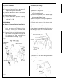
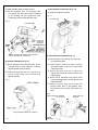
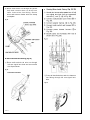
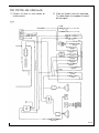
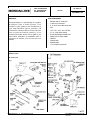
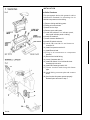
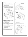
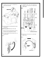
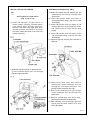
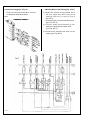
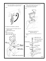
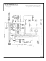
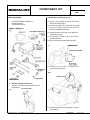
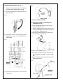
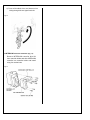
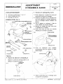
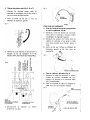
Accessory
Application
Publications No.
HP 190 8112
TYPE 11
AM/FM RADIO
GL1100
Issue Date
DECEMBER
1981
PREFACE
TOOLS REQUIRED
Congratulations on purchasing this quality
Type 11 Honda Motorcycle Audio system.
This booklet is your guide to the installation
of your new Type II Honda Motorcycle
Radio. Please take the time to read the
booklet carefully. (Your authorized Honda
dealer will be glad to provide further information or assistance and is equipped to handle
your further service needs.)
•
•
•
•
•
•
•
•
•
•
•
•
HONDA MOTOR CO., LTD. 1981• All Rights Reserved
Ratchet and 12" extension
7 and 10 mm sockets
8, 10, and 14 mm box wrenches
Drill
1/8", 7/32", 3/16", and 1/4" Bits
2.5, 4, 8 mm hex wrench
#1 and #2 Phillips screwdrivers
Sharp knife or Razor blade
Hammer
Center punch
Masking tape
17 mm open-end wrench
08118-MB910-95 Printed in Japan
28 4-3 60 2-0 0
2 of 1 1
OVERALL LAYOUT
Fig. 9
INSTALLATION
■ Outline Procedures
This section gives general information needed
for mounting the individual radio components
on and in the fairing.
A) Fairing
1) Install radio on fairing before mounting
fairing on motorcycle. (Remove fairing
from your motorcycle when already
mounted).
2) Remove fairing parts.
3) Drill unit mount holes.
4) Install six wire clips.
5) Install windshield on fairing before installing speakers.
6) Install radio indicator I on indicator panel
II , then install indicator panel on fairing.
7) Install speakers III.
8) Install nutplate IV.
9) Install Power Amplifier in fairing.
10) Install radio funer VI.
11) Install the radio controller VII.
12) Install controller base panel VIII
13) Install radio switch sub-wire.
14) Connect adapter harness and wires inside
fairing by working through left turn
signal lens hole.
B) Motorcycle frame and handlebar
1) Remove travel trunk and seat. Unscrew
four shelter bolts (M6, one on each side
at front and rear) to route antenna feeder.
2) Install antenna mount and antenna IX.
3) Route antenna feeder along the frame
tube.
4) Install radio switch X on left handlebar
lever bracket and route the wires.
3 of 11
C) Fairing installation
■ Reworking on Fairing —
1) Install fairing on motorcycle.
Speaker mounting holes-
2) Connect motorcycle wire harness 9-P
coupler to fairing wire 9-P coupler.
1) Remove 18 mm grommet.
3) Connect radio switch wire to switch subwire.
4) Connect antenna feeder.
5) Confirm that radio operates properly.
Reinstall parts removed in step 2 or (A)
and in step 1 of (B).
REWORKING
■ Remove Fairing and Fairing Parts (Fig.10)
1) Install radio on fairing before mounting
fairing on motorcycle. (Remove fairing
from your motorcycle when already
mounted).
2) Remove right and left fairing pockets,
right and left turn signal lenses, right and
left nutplates, left hole cover and indicator base panel from fairing. (Fig.10)
Fig. 10
2) Lightly roll template so that it will follow
contour of fairing snugly.
3) Position template on fairing with its upper
and outer edges aligned with those of
fairing as indicated by arrows.
4) Attach template to fairing using adhesive
tape where shown.
5) Punch mark centers of four holes with a
drift and hammer.
6) Drill 6 mm holes through marked centers.
To obtain a more balanced response with
richer, deeper bases, drill two 50 mm holes in
the fairing so as to link the speaker box with
the inside of the fairing.
Fig. 11-1
RIGHT HAND SHOWN, LEFT
SIMILAR
ADHESIVE
TAPE
TEMPLATE
—Power amplifier mounting holes7) Drill two 5.5 mm holes through concaves
in fairing.
Fig. 11-2
LEI-1 NU I PLATE
4 of 11
—Indicator panel mounting holes-
INSTALLATION ON FAIRING
8) Drill four 15 mm holes through fairing at
the marked locations, and 40 mm holes as
shown.
■ Radio Indicator Installation (Fig. 12, 13,
14)
Fig. 11-3
1) Install radio indicator in indicator panel as
shown.
Fig. 12
15 mm HOLE
40 mm HOLE
9) Install six wire clips to temporarily secure
wires as shown.
Fig. 11-4
6 WIRE CLIPS
2) Insert the cushion rubbers into the holes
with the thick ends facing out.
3) Slide special washers into cushion rubbers
from inside fairing.
4) Attach the top of the base bracket to fairing using two screw-washer combinations
and wing nuts. Tighten wing nuts with
pliers while holding the screws with
screwdriver.
Fig. 13
THICK END
BASE BRACKET
CUSHION RUBBER
SPECIAL WASHER
5 of 11
5) Install indicator panel on base bracket.
6) Route indicator wire out through right
turn signal lens hole and sub-wire harness
G out -through left turn signal lens hole.
Temporarily secure wires with wire clips.
■ Left Nutplate Installation (Fig. 16)
1) Install left nutplate as shown.
Fig. 16
LEFT NUTPLATE
Fig. 14
2 SEMS SCREWS
ROUTE TO LEFT TURN SIGNAL LENS HOLE AND
ATTACH TEMPORARILY BY WIRE CLIP
■
Speaker Installation (Fig. 15)
1) Route speaker wires through holes in fairing and position each speaker in fairing
align studs with holes in fairing.
2) Reaching through the turn signal lens
holes, install wing nuts on studs and
tighten securely.
■ Power Booster Installation (Fig. 17)
1) Insert booster into fairing through right
turn signal lens hole.
2) Insert booster studs into holes in fairing
and install using a cap nut on each stud.
Tighten securely.
3) Route the gray wire out to right turn
signal lens hole and connect to wire from
right speaker.
4) Route wires bundled with yellow tape
under headlight and out through left turn
signal lens hole.
5) Remove yellow tape from wires and
connect white wire to left speaker wire.
Temporarily secure other wires with wire
clips.
Fig. 15
Fig. 17
WIRE FROM RIGHT SPEAKER
I 2 CAP NUTS WIRE
GRAY
WI
R
RIGHT SPEAKER SHOWN LEFT SIMILAR
6 of 11
POWER
AMPLIFIER
G
WIRE FROM LEFT
SPEAKER
■ Radio Tuner Installation (Fig. 18, 19)
■ Radio Controller Installation (Fig. 20)
1) Attach right nutplate with radio to fairing.
Remove radio controller blind lid from
controller holder. Slide the radio controller into the holder and install using
four hex socket bolts.
Fig. 18
RADIO TUNER
Fig. 20
CONTROLLER HOLDER
RADIO CONTROLLER
2) Route wires bundled with green tape
under headlight towards left and out
through left turn signal lens hole. Temporarily secure wires with wire clip.
3) Route wire to radio controller under
headlight towards left side and out
through left pocket hole. Secure wire
with wire clip temporarily.
4) Pass indicator wire out through right turn
signal lens hole and connect it to wire
from indicator.
5) Connect two antenna feeders to radio and
route them out through hole above 9-P
connector.
4 SOCKET HEAD BOLTS
■ Controller Base Panel Installation (
Fig. 21, 22)
1)
Slide controller base plate into fairing and
install using four socket head bolts. Place
caps over heads of socket bolts.
Fig. 21
4 SOCKET HEAD BOLT
W / W A S H E R S (M5 x 20
mm)
Fig. 19
WIRES BUNDLED WITH YELLOW TAPE
INDICATOR WIRE
FROM INDICATOR
4 CAPS
CONTROLLER
WIRE
ANTENNA
FEEDER
EXTENSION
RADIO
TUNER
CONTROLLER
BASE PLATE
7 of 11
2) Route radio wires out through left pocket
hole and connect them to wires from
radio. Insert wires into fairing. Secure
wires and antenna feeder with wire clamp
on nutplate.
Fig. 22
■ Radio Switch Sub-wire Routing (Fig. 23)
1) Route radio switch sub wire out through
left turn signal lens hole and secure with
wire clip as shown.
Fig. 23
RADIO SWITCH SUB-WIRE
7) Press all bundled wires and wire harness
into fairing through left turn signal lens
hole.
Fig. 25
8 of 11
■ Antenna Installation (Fig. 26, 27, 28, 29)
Fig. 27
1) Remove seat by removing hex socket
bolts (one on each side) and pulling it
backward.
2) Remove the top compartment by removing four bolts (M6) (one on each side at
front and rear) and pulling it upward. See
Motorcycle Service Manual.
3) Install antenna on antenna mount and
route antenna feeder through mount.
Antenna is collapsible. Install the antenna
so it folds along the frame. This is for
convenience when covering the motorcycle, or putting the motorcycle in a
garage.
4-1 Press grommets into holes at ends of
mount. Position antenna mount on rear
trunk stay and install using bolts
w/washers.
• Tighten nuts (M12) to 0.1 kg-m torque.
• Tighten hexagon bolt (M6 x 12 mm) to 0.81.2 kg/m (6-9 ft/lb) torque.
Fig. 26
4-2 Position antenna base on seat guard pipe
and install using bracket, holder and two
flange bolts (M6 x 25 mm).
• Tighten the flange bolt (M6 x 25 mm)
to 0.8-1.2 kg/m (6-9 ft/lb) torque.
• Tighten the hexagon nut (M12) to
0.1 kg/m torque.
■ Antenna Feeder Routing (along frame
tube) (Fig. 30, 31)
Route antenna feeder as shown.
2) Route switch wires along with turn signal
switch wires, and attach them to handlebar with wire bands positioned where
shown.
Fig. 31
ANTENNA FEEDER
■
Fairing Installation (Fig. 34)
1) Install fairing on motorcycle.
2) Connect motorcycle wire 9-P connector
and ground wire to fairing connector and
ground connection. Place connector
cover over connections.
3) Connect radio switch wires to switch subharness wires.
4) Connect antenna feeder to feeder extension and attach it to fairing mount frame
with wire band.
Fig. 34
GROMMET
■ Radio switch installation (Fig. 32, 33)
1) Remove plug from left handlebar lever
bracket and install radio switch.
RADIO SWITCH
SUB-WIRE
RADIO SWITCH
ANTENNA
FEEDER
EXTENSION
ANTENNA FEEDER
10 of 11
9-P CONNECTOR
GROUND WIRE
11of 11
Application
Accessory
Publications No.
HP 189 8112
TYPE II INTERCOM
CB TRANSCEIVER
CASSETTE DECK
GL1100
Issue Date
DECEMBER 1981
PREFACE
TOOLS REQUIRED
Congratulations on purchasing this quality
Hondaline Type II Audio system. This
booklet is your guide to the installation of
your new Hondaline Type II Intercom, CB
Transceiver Cassette Deck. Please take the
time to read the booklet carefully. (Your
authorized Honda dealer will be glad to provide further information or assistance and is
equipped to handle your further service
needs.)
•
•
•
•
•
•
•
•
•
•
•
•
Ratchet and 12" extension
7 and 10 mm Sockets8, 10, and 14 mm Box wrenches
Drill
1/8", 7/32", 3/16", and 1/4" Bits
2.5, 4, 8 mm Allen wrench
#1 and #2 Phillips screwdrivers
Sharp knife or Razor blade
Hammer
Centerpunch
Masking tape
17 mm open-end wrench
PARTS LIST
■ Intercom
Fig. 1
HONDA MOTOR CO., LTD. 1981- All Rights Reserved
08118-MB980-95 Printed in Japan 284-
3603-00
INSTALLATION
■ Outline Procedures
This paragraph deals with general outline
information needed for mounting the individual components on the fairing.
1) Remove fairing and fairing parts.
2) Drilling unit mount holes.
3) Install six wire clips.
4) Remove some radio parts.
5) Install CB indicator I on indicator panel,
then install indicalor panel on fairing.
6) Install CB module II.
7) Install Antenna distributor III.
8) Install CB switch sub wire.
9) Install CB controller N. and Intercom
controller IX.
10) Install Component terminal V.
11) Install Branch lead.
12) Plug in all connectors to component
terminal.
13) Route wires inside fairing.
14) I nstal I Cassette deck VI.
15) Install CB Switch VII on left handle lever
bracket and route wire.
16) Install CB Passenger switch VIII.
17) Route Junction lead along with frame
pipe.
18) Install fairing on motorcycle and connect
wires.
19) Confirm that all system operate properly.
Reinstall parts removed in step 1.
Fig. 6
REWORKING
ADHESIVE TAPE
■ Remove Fairing and Fairing Parts (Fig. 5)
1) Remove fairing from your motorcycle
when already mounted.
COMPONENT TERMINAL
2) Remove right and left fairing pockets,
right and left turn signal lenses, right and
left nutplates and left hole cover indicator
base panel from fairing (Fig. 5).
Fig. 5
6 mm HOLES
Fig. 7
CB MODULE
TEMPLATE
RIGHT
POCKET
LEFT POCKET
ADHESIVE
TAPE
■ Reworking on fairing (Fig. 6, 7, 8, 9) (
Drilling component terminal, CB module
and casset deck mount holes)
—CB, component terminal1) Lightly roll template so that it will follow
contour of fairing snugly.
—Cassette deck6) Punch mark centers of two holes with a
drift and hammer.
7) Drill 6 mm holes through marked centers.
Fig. 8
2) Position template on fairing with its upper
and outer edges aligned with those of
fairing as indicated by arrows.
3) Attach template to fairing using adhesive
tape where shown.
4) Punch mark centers of four holes with a
drift and hammer.
5) Drill 6 mm holes through marked centers.
3 of 11
8) Install six wire clips to temporarily
secure wires as shown.
Fig. 9
2) Unbundle three ties and disconnect
adapter wire harness and RADIO/PA
JOINT WIRE.
Fig. 11
6 WIRE CLIPS
9) Install windshield on fairing before installing speakers.
■ Removing Radio Parts (Fig. 10, 11, 12)
Remove several radio parts from fairing
as follows when already radio mounted.
1) Pull out bundled wires through left turn
signal lens hole.
Fig. 10
ADAPTER WIRE HARNESS
3) Disconnect and remove one antenna
feeder of two.
Fig. 12
ANTENNA
FEEDER
RADIO TUNER
4 of 11
INSTALLATION ON FAIRING
CB
■ CB Indicator Installation
(Fig. 13, 14, 15, 16)
1) Install CB indicator in right hole of indicator panel. (Remove indicator panel
from fairing when already mounted.
Remove volt-meter from right hole when
already mounted and install it in central
hole and install two blind lid in both side
hole of volt-meter.)
■ CB Module Installation (Fig. CB-3)
1) Insert CB module and CB bracket (not yet
assembled) into fairing through right
pocket hole.
2) Insert CB module studs into holes in
fairing and install using a cap nut on each
stud loosely.
3) Insert CB bracket stud into holes of CB
module and then insert studs into holes
and install using a flunge nut on stud
loosely.
4) Insert CB bracket stud into holes in fairing and install using a cap nut on each
stud loosely.
5) Tighten flunge nut securely first, and then 4
cap nuts.
Fig. 15
2)
Reinstall indicator panel on base bracket.
3) Rout indicator panel wire out through
right turn signal less hole.
Fig. 14
2 SEMS SCREWS (M4)
6) Route wires (with fuses and miniture
connectors) under headlight and out
through left turn signal lens hole. Temporarily secure wires with wire clips.
7) Route wires bounded with yellow tape
under headlight and out through left
pocket hole.
8) Remove yellow tape from wires and
secure wires with wire clip temporarily.
9) Pass indicator wire out through right turn
signal lens hole and connect it to wire
from CB indicator.
5 of 11
Fig. 16
2) Pass antenna feeder of distributor indicated "ANTENNA" out through round
hole above 9-pin connector.
3) Connect antenna feeder of distributor
indicated "AM/FM RADIO" to antenna
feeder from radio tuner.
4) Connect antenna feeder of distributor
indicated "CB-SET" to antenna feeder
from CB module.
5) Connect CB controller wire to wire from
CB module.
6) Tighten green ground wire with double
sems screw.
Fig. 18
■ Antenna Distributor Installation (
Fig. 17, 18)
1) Install antenna distributor on left nut
plate as shown.
CB ANTENNA
FEEDER
CB CONTROLLER
WIRE
RADIO ANTENNA
FEEDER
Fig. 17
SEMS SCREW
COLLAR
ANTENNA
DISTRIBUTOR
CUSHION
RUBBER
6 of 11
TO COMPONENT
TERMINAL
■ CB Switch Sub Wire Installation (Fig. 19)
■ Component Terminal Installation (Fig. 21)
1) Route CB switch sub-wire out through
left turn signal lens hole and secure with
wire clip as shown. (Route along radio
switch sub wire)
1) Insert component terminal into fairing
through left turn signal lense hole.
2) Insert component terminal studs into
holes in fairing and install using a cap nut
on each stud. Tighten securely.
Fig. 19
3) Pull out wires through left turn signal lens
hole and secure with wire clip.
Fig. 21
CAP NUTS
COMPONENT
TERMINAL
■ Branch Lead Installation (Fig. 22)
■ CB Controller Installation (Fig. 20)
Remove CB controller blind lid from controller holder and slide CB controller into
controller holder and install using four
socket bolts.
Fig. 20
1) Pass branch lead in through hole above 9pin connector and plug in to component
terminal.
2) Attach lead hooks and secure branch lead with
them where shown.
Fig. 22
7 of 11
■ Connector Plugging in (Fig. 23)
Plug in all connectors should be connect
to component terminal as shown.
Fig. 23
COMPONENT TERMINAL
■ Routing Wires Inside Fairing (Fig. 24, 25)
1) Bundle all harness wires passed out of
left turn signal lens hole (not yet connected) with ties (1) and (2) ((a) in
Fig. INT-6).
2) Connect Inter corn wires and other wires
((b) in Fig. INT-6).
3) Connect audio main harness to sub
harness G, fairing wire and other wires
((c) in Fig. INT-6).
4) Bundle wires and harness with ties as
shown ((d) in Fig. INT-6).
8 of 11
5) Press all bundled wires and harness into
fairing through left turn signal lens hole.
Fig. 25
3) Route wire through left turn signal lens
hole and secure wire temporarily.
4) Set cassette deck in deck base.
Fig. 27
CASSETTE DECK
■ Cassette Deck Installation (Fig. 26, 27)
1) Install front and rear cassette deck nut
plates as shown.
2) Install Cassette deck base.
Fig. 26
■ CB Switch Installation
(Fig. 28, 29, 30, 31)
1) Install CB switch and Radio switch as
shown.
2) Route switch wire along with turn signal
switch wires and radio switch wire and
attach them to handlebar with wire bands
positioned where shown.
■ Securing Junction Lead (Fig. 31)
1) Route the junction lead along the antenna
feeder and secure with plastic tie where
shown.
2) Attach connector holder to left side
cover, and insert passenger's Din conector
in holder.
FAIRING INSTALLATION (Fig. 32)
1) Install fairing on motorcycle.
2) Connect motorcycle wire 9-P connector
and ground wire to fairing connector and
ground connection. Place connector cover
over connedions.
3) Install CB passenger switch on rear
luggage as shown.
CB PASSENGER
SWITCH
Fig. 30
3) Connect radio switch wires to switch subharness wires.
4) Connect CB switch wires and CB passenger switch sub wires to CB switch sub
harness wires.
5) Connect antenna feeder to feeder from
distributor.
6) Connect branch lead to junction lead and
attach it and antenna feeder to fairing
mount flame with wire band.
Fig. 32
GROMMET
BAND RUBBER
BRANCH
LEAD
CAP NUT
SCREW
BAND
RADIO SWITCH
4) Route CB passenger switch sub wire along
with antenna feeder.
Fig. 31
JUNCTION LEAD
CONNECTOR HOLDER
INTERCOM JUNCTION LEAD
ANTENNA FEEDER
CONNECTOR
HOLDER
ANTTENNA
FEEDER
CB PASSENGER SWITCH
SUB WIRE
10 of 11
CB PASSENGER
SUB-WIRE
9-P CONNECTOR
GROUND WIRE
WIRE ROUTING AND FUSES (Fig. 33)
1) Connect all wires to wire harness terminals properly.
Fig. 33
2) Fuses are located in left turn signal base.
To replace fuses, remove left turn signal.
Publications No.
COMPONENT KIT
Issue Date
1983
TOOLS REQUIRED
•
•
•
# 1 and # 2 Phillips screwdrivers
8mm Box wrench
2.5mm Allen wrench
■ Reworking on fairing (Fig. 3,4)
1) Lightly roll template so that it will follow
contour of fairing snugly.
2) Position template on fairing with its upper
and outer edges aligned with those of
fairing as indicated by arrows.
3) Attach template to fairing using adhesive
tape where shown.
4) Punch mark centers of two holes with a
drift and hammer.
5) Drill 6 mm holes through marked centers.
Fig. 3
ADHESIVE TAPE
COMPONENT TERMINAL
6 mm HOLES
6) Install six wire clips to temporarily
secure wires as shown.
Fig. 4
6 WIRE CLIPS
REWORKING
■
Fig. 2
Remove Fairing Parts (Fig. 2)
Remove left fairing pocket and left turn
signal lense.
LEFT TURN SIGNAL
LEFT POCKET
HONDA MOTOR CO., LTD. 1983. All Rights Reserved
7) Install windshield on fairing before installing speakers.
284-3799-00
Printed in Japan
■ Removing Radio Parts (Fig. 5, 6, 7 )
Fig. 7
Remove several radio parts from fairing
as follows when already radio mounted.
1) Pull out bundled wires through left turn
signal lens hole.
Fig. 5
INSTALLATION ON FAIRING
■ Component Terminal and ALC-Amplifier
Installation (Fig. 8)
1) Insert component terminal into fairing
through left pocket hole.
2) Unbundle three ties and disconnect
adapter wire harness and RADIO/PA
JOINT WIRE.
2) Insert component terminal studs into
holes in fairing and install using a cap nut
on each stud. Tighten securely.
3) Pull out wires through left turn signal lens
hole and secure with wire clip.
Fig. 8
Fig. 6
■ Branch Lead Installation (Fig. 9 )
1) Pass branch lead in through hole above 9pin connector and plug in to ALC-Amplifier.
2) Attach lead hooks and secure branch lead with
them where shown.
RADIO/P.A.
JOINT WIRE
ADAPTER WIRE HARNESS
3) Disconnect and remove one antenna
feeder of two.
■ Connector Plugging in (Fig. 10)
Plug in all connectors should be connect
to component terminal as shown.
■ Routing Wires Inside Fairing (Fig.11, 12 )
1) Bundle all harness wires passed out of
left turn signal lens hole (not yet connected) with ties (1) and (2) ((a) in
Fig. 1 1).
2) Connect COMPONENT TERMINAL wires and
other wires ((b) in Fig. 11).
3) Connect audio main harness to sub
harness G, fairing wire and other wires
((c) in Fig. 11).
4) Press all bundled wires and harness into
fairing through left turn signal lens hole.
Fig. 12
■ INTERCOM Controller Installation (Fig. 13)
Remove INTERCOM controller blind lid
from controller holder and slide INTERCOM
controller into controller holder and install
using four socket bolts.
Fig. 13


![An 8080 Simulator for the 6502, KIM-1 Version [1978]](http://vs1.manualzilla.com/store/data/005862327_1-86881d05118ae2e6f54412aa1d9ee60a-150x150.png)