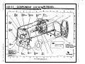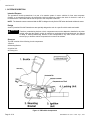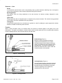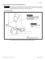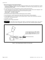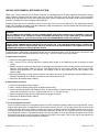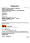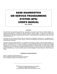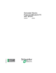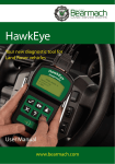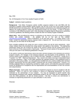
1
Modified Vehicle Engineering
Body Builder Advisory Service:
1-800-635-5560
QUALIFIED VEHICLE
MODIFIER PROGRAM
QVM Bulletin No. Q-49
Date: July 7, 1997
Retain This Bulletin in Your Technical Bulletins Binder for Future Reference
ECONOLINE AIR BAG LIGHT
BACKGROUND:
This bulletin was developed to assist final-stage manufacturers in avoiding potential illumination of air bag lights. Ford has
identified the following as potential final-stage manufacturer-related causes of air bag light illumination:
seat wiring harness disconnected from seat belt buckle pretensioners
seat wiring harness damaged during final-stage manufacturing process
seats removed and/or replaced with other seats
seat removed in order to eliminate the seating position
FINAL-STAGE MANUFACTURER RESPONSIBILITY:
Final-stage manufacturers MUST properly assemble the seat, seat belt pretensioner, and seat wiring harness/connectors,
ensuring all seat wiring is undamaged, routed and secured away from sharp edges and moving parts of the seat track
mechanism for fit and function.
Final-stage manufacturers must exercise caution when installing interior components so as not to damage the seat belt
pretensioner circuitry. Care must be taken to prevent damage to the seat wiring harness running along the floor from the
“B” pillar to the driver and passenger seats. (Refer to Attachment I.)
As noted in the 1997 Ford Incomplete Vehicle Manual (IVM), “The seat belt buckle pretensioner, air bags and electronic
sensor module are bar coded with a unique serial number which is matched to the vehicle VIN. The completed vehicle
must contain the same seat belt buckle pretensioner, air bags and electronic sensor module that were installed in the
incomplete vehicle.” (Refer to Attachment II for pretensioner safety instructions and handling information.)
Final-stage manufacturers removing the front passenger seat from their final assembly process in vehicles equipped
without the optional passenger air bag must replace the air bag Electronic Crash Sensor (ECS) module with service part
number F7UB-14A685-A to prevent the air bag light from coming on. (Refer to Attachment III for installation procedure.)
SUMMARY:
Final-stage manufacturers must ensure the seat wiring harness is reconnected and undamaged during the final
manufacturing process. If air bag light is “on” or “flashing,” recheck all seat wiring harnesses for damage and proper
connections.
Please ensure that your suppliers are informed of this bulletin where applicable. If you have any questions concerning this
bulletin, please contact the Ford Body Builders’ Advisory Service on 1-800-635-5560 or FAX 313-337-2754.
Alex Jowa
Body Builders Advisory Service Section
Attachments
QVM Bulletin No. Q-49 — Date: July 7, 1997
Page 1 of 23
Attachment I
Page 2 of 23
QVM Bulletin No. Q-49 — Date: July 7, 1997
QVM Bulletin No. Q-49 — Date: July 7, 1997
Attachment I
Page 3 of 23
Attachment I
Page 4 of 23
QVM Bulletin No. Q-49 — Date: July 7, 1997
Attachment II
PYROTECHNIC BUCKLE PRETENSIONER — PBP
QVM Bulletin No. Q-49 — Date: July 7, 1997
Page 5 of 23
Attachment II
THIS DOCUMENT
These instructions concern the handling of the PBP when fitting to a seat prior to installation in a vehicle.
The purpose of the instructions is to give general advice in order to eliminate the risk of damage and unnecessary claims
resulting from incorrect handling or insufficient knowledge of the product.
SAFETY
In this document, particularly important information is distinguished in the following ways:
NOTE:
NOTES provide key information to make procedures easier or clearer to understand.
WARNING
A WARNING indicates special procedures which must be followed to avoid personal injury or damage to the unit.
Provide key information in the text.
PRODUCT LABEL
CAUTION
Pretensioner cannot be repaired. Use
Ford diagnostic instructions to determine
if unit is defective. If defective, replace
and dispose of entire unit as directed in
instructions. Never perform diagnosis
using electrically powered test equipment
or probing devices. Tampering or mishandling may result in personal injury. For
special handling instructions, refer to
Ford shop manual.
MISE EN GARDE
Figure 1: Product Label on the Unit
Page 6 of 23
QVM Bulletin No. Q-49 — Date: July 7, 1997
Attachment II
Table of Contents
page
III. SYSTEM DESCRIPTION . . . . . . . . . . . . . . . . . . . . . . . . . . . . . . . . . . . . . . . . . . . . . . . . 8
Intended Purpose . . . . . . . . . . . . . . . . . . . . . . . . . . . . . . . . . . . . . . . . . . . . . . . . . . . . . . 8
Design . . . . . . . . . . . . . . . . . . . . . . . . . . . . . . . . . . . . . . . . . . . . . . . . . . . . . . . . . . . . . . . . 8
Structure . . . . . . . . . . . . . . . . . . . . . . . . . . . . . . . . . . . . . . . . . . . . . . . . . . . . . . . . . . . . . . 8
Function . . . . . . . . . . . . . . . . . . . . . . . . . . . . . . . . . . . . . . . . . . . . . . . . . . . . . . . . . . . . . . 9
III. HEALTH HAZARD DATA . . . . . . . . . . . . . . . . . . . . . . . . . . . . . . . . . . . . . . . . . . . . . 10
III. SAFETY INSTRUCTION AND HANDLING INFORMATION . . . . . . . . . . . . . . . . 11
How to Handle the PBP . . . . . . . . . . . . . . . . . . . . . . . . . . . . . . . . . . . . . . . . . . . . . . . . 11
General Information on Handling . . . . . . . . . . . . . . . . . . . . . . . . . . . . . . . . . . . . . . . . 12
Electrical Safety . . . . . . . . . . . . . . . . . . . . . . . . . . . . . . . . . . . . . . . . . . . . . . . . . . . . . . . 13
Diagnostic Monitor . . . . . . . . . . . . . . . . . . . . . . . . . . . . . . . . . . . . . . . . . . . . . . . . . . . . . 13
Back-up Power Supply . . . . . . . . . . . . . . . . . . . . . . . . . . . . . . . . . . . . . . . . . . . . . . . . . 13
Removal of PBP . . . . . . . . . . . . . . . . . . . . . . . . . . . . . . . . . . . . . . . . . . . . . . . . . . . . . . 14
Storage and Safety Precautions . . . . . . . . . . . . . . . . . . . . . . . . . . . . . . . . . . . . . . . . . 15
Disposal of PBP Components . . . . . . . . . . . . . . . . . . . . . . . . . . . . . . . . . . . . . . . . . . . 15
Activating PBPs after Removal from Vehicle – Out-of-Vehicle Activation . . . . . . 15
IV. APPENDIX . . . . . . . . . . . . . . . . . . . . . . . . . . . . . . . . . . . . . . . . . . . . . . . . . . . . . . . . . . 17
Material Safety Data Sheet . . . . . . . . . . . . . . . . . . . . . . . . . . . . . . . . . . . . . . . . . . . . . 17
Specific Assemblies . . . . . . . . . . . . . . . . . . . . . . . . . . . . . . . . . . . . . . . . . . . . . . . . . . . 21
QVM Bulletin No. Q-49 — Date: July 7, 1997
Page 7 of 23
Attachment II
II. SYSTEM DESCRIPTION
Intended Purpose
The pyrotechnic buckle pretensioner is a part of a restraint system in motor vehicles for front seat occupants.
Contrary to a conventional buckle, the pyrotechnic buckle pretensioner reduces the slack of the belt in case of a
frontal accident. That means that the risk of injuries to the occupants is reduced.
NOTE: The electronic sensor connected with the PBP is designed to only fire the PBP when the frontal accident is severe.
Design
Autoliv Pyrotechnic Buckle Pretensioners are specially designed to work in a specific vehicle make and model.
WARNING
Therefore, pretensioning devices or their components must not be adapted or installed in any other
vehicle other than the specific vehicle for which they are designed and manufactured. Any attempt
to adapt or install pretensioning devices or their components in any other vehicle can result in
severe injury or death to vehicle occupants in the event of an accident.
Structure
The PBP consists of the following 4 main components:
1. Buckle
2. Mounting Bracket
3. Ignition Unit
4. Locking Unit
Figure 2: PBP’s Main Components
Page 8 of 23
QVM Bulletin No. Q-49 — Date: July 7, 1997
Attachment II
Structure — Cont.
Buckle
A conventional seat belt buckle, with a compensating mass to avoid inadvertent unlatching due to the dynamic
forces of the push button or other internal components during PBP activation.
Mounting Bracket
The restraint forces are being transferred to the seat structure via brackets uniquely designed for each
application.
Ignition Unit
The gas generator with its integrated squib is crimped into the pressure chamber. The electrical energy provided
by the sensor unit fires the propellant in the gas generator.
Locking Unit
A piston with several balls on its circumference is guided in a tube. By loading the system opposite the tension
direction, the balls lock between piston and tube.
Function
When a severe accident occurs, an external sensor unit sends an electrical signal to the ignition unit of the
pretensioner. The ignition unit initiates a chemical reaction which creates gases that drive the piston/cable assembly
forward, applying tension to the buckle and reduces seat belt slack.
Pretensioning (Figure 3)
When the vehicle deceleration exceeds a
predetermined threshold level, the electromechanical sensor unit provides the electrical
energy to fire both (driver and passenger side)
gas generators. The pressure applied to the
piston pulls the buckle down via the cable and
reduces the slack of the seat belt.
Figure 3: Pretensioning
Locking Position (Figure 4)
As soon as the direction of movement changes,
the balls will be pressed between the cone on
the piston and the inner diameter of the tube.
The forces applied by the occupants are
transferred to the seat structure.
Figure 4: Locking Position
QVM Bulletin No. Q-49 — Date: July 7, 1997
Page 9 of 23
Attachment II
II. HEALTH HAZARD DATA
Effects of overexposure: There is no potential exposure to propellant from an undamaged sealed pretensioner as
manufactured by Autoliv. The gas generating powder is a nitrocellulose-based material sealed within a small metal
capsule housed in the buckle pretensioner unit.
In the unlikely event of an exposure to the gas generant sealed within the PBP (i.e., the unit ruptured due to
mishandling or tampering), refer to the appropriate Material Safety Data Sheet (MSDS) for the specific assembly.
NOTE: The MSDS for pretensioning assemblies is located in the Appendix of this manual.
Page 10 of 23
QVM Bulletin No. Q-49 — Date: July 7, 1997
Attachment II
III. SAFETY INSTRUCTION AND HANDLING INFORMATION
WARNING
Read and comply with all WARNINGS, CAUTIONS and safety instructions before proceeding with
any pyrotechnic buckle pretensioner service, removal, or activation. Failure to follow such warnings,
cautions and safety instructions may result in severe personal injury.
How to Handle the PBP
Figure 5: Caution Areas for a Typical Pyrotechnic Buckle Pretensioner
QVM Bulletin No. Q-49 — Date: July 7, 1997
Page 11 of 23
Attachment II
General Information on Handling
WARNING
General
The electrical connector on the PBP assembly is provided with a safety shunt. Tampering with this connector
can disable the safety shunt and could cause inadvertent deployment and severe personal injury.
The PBP is delivered with a shunt clip. This clip must be removed just before connecting the electrical wire with
the corresponding plug at the wire coming from the seat. Remove the shunt clip only for this purpose! Do not
touch the electrical pins inside the connector! Do not touch the pins with any electrical devices or with
electrostatically charged parts! Hold the pretensioner as described in Figure 5, when the shunt clip is removed!
Activated or unactivated
The design of some pyrotechnic buckle pretensioners will not allow for easy determination of condition, i.e.,
activated or unactivated (live); therefore, unless the handler has direct knowledge of a unit’s condition, the unit
must be considered unactivated (live) and capable of inflicting severe personal injury.
After a vehicle accident
In the unlikely event that, as a result of a vehicle accident, one pretensioner activates and one does not, it must
be assumed that the unactivated pretensioner is still functional. Therefore, follow all WARNINGS, CAUTIONS
and safety instructions for an unactivated (live) pretensioner.
After a vehicle accident, the complete seat belt system, including the pyrotechnic buckle pretensioners, must be
replaced. Even if only one pretensioner or no pretensioner was activated, all pretensioners in the vehicle have to
be replaced. Therefore, follow all WARNINGS, CAUTIONS and safety instructions for an unactivated (live)
pretensioner.
Servicing
The PBP assembly cannot be serviced. Never attempt to open or dismantle the PBP assembly.
Never attempt to disassemble unactivated PBPs or otherwise breach the integrity of the unit, including the
sealed metallic gas generator capsule.
Never point the pretensioner tube towards yourself or others. Failure to comply with these directions could result
in severe personal injury.
Page 12 of 23
QVM Bulletin No. Q-49 — Date: July 7, 1997
Attachment II
Electrical Safety
Delivery (Figure 6)
When delivered from Autoliv, the PBP is equipped
with a Safety Shunt in the form of a shunt clip.
The gas generator squib is thereby electrically
shorted and safe to handle.
Figure 6: Delivery
Connection to the Vehicle (Figure 7)
This shunt clip must be removed just
before connecting the electrical wire with the
corresponding connector coming from the seat.
The gas generator squib is no longer electrically
shorted, but the unit is now a part of the vehicle
safety system.
Figure 7: Connection
Diagnostic Monitor
This is a part of the sensor unit and monitors the condition of the air bag system and PBP system. If faults occur in
the air bag or pretensioning system, an instrument panel warning device will be activated.
WARNING
If the warning device for the air bag or pretensioning system is activated during driving the vehicle,
the air bag and/or pretensioning system has to be checked immediately by authorized personnel.
Driving with a non-functional air bag/pretensioner system can result in severe injury or death to
vehicle occupants in the event of an accident.
Backup Power Supply
A backup power supply is typically included for the air bag and PBP system to provide the electrical energy necessary
for air bag deployment and seat belt pretensioning if the battery or cables are damaged in an accident before the
electronic sensor module activates the devices.
WARNING
The backup power supply for undeployed air bags/PBPs must be deactivated after an accident or
before service to prevent accidental deployment and personal injury. Read carefully the vehicle
manufacturer’s service manual.
This is accomplished by disconnecting the power supply assembly from the vehicle electrical system or by
disconnecting or cutting the battery cables. Leave the PBP installed for at least 30 minutes (or the length of time
directed by the manufacturer for the specific make and model). This will allow the backup power supply to discharge.
Once the system is discharged, further removal procedures can be followed.
QVM Bulletin No. Q-49 — Date: July 7, 1997
Page 13 of 23
Attachment II
Removal of PBP
This section presumes that the mounted PBPs have to be removed due to a vehicle accident, and the PBPs have to
be replaced.
Two things are important when demounting and removal of PBPs:
1. Is the PBP activated or unactivated (live)?
2. Is the PBP electrically secured?
Activated or Unactivated (Live)
The design of some PBPs will not allow for easy determination of condition; i.e., ACTIVATED or UNACTIVATED
(LIVE).
WARNING
Therefore, unless the handler has direct knowledge of a unit’s condition, the unit must be
considered unactivated (live) and capable of inflicting severe personal injury.
Electrically Secured
As a result of the comments above, the electrical pins inside the gas generator have to be electrically shorted. This
can be done in two ways:
Alt. 1.
Alt. 2.
Figure 8: Electrically Securing of the Gas Generator
Removing UNACTIVATED (Live) PBPs from Vehicle
Once the PBP is disconnected from the vehicle electrical system, follow the vehicle manufacturer’s guidelines to
remove the PBP.
WARNING
Never attempt to disassemble an unactivated (live) PBP or otherwise breach the integrity of the
unit, including the sealed metallic gas generator capsule. Never point the tube towards yourself
or others. Failure to comply with these directions could result in severe personal injury.
WARNING
Follow all WARNINGS, CAUTIONS and safety instructions provided in this manual and supplied
by vehicle manufacturer.
Failure to follow such WARNINGS, CAUTIONS and safety instructions may result in severe
personal injury.
Page 14 of 23
QVM Bulletin No. Q-49 — Date: July 7, 1997
Attachment II
Storage and Safety Precautions
Handling of PBPs
1. When carrying an unactivated PBP, the tube must always be pointed down and away from others. Uninstalled
units, if activated, may release projectiles.
2. When carrying or handling PBPs, care should be taken to keep fingers away from the cable assembly and the
upper areas of the pressure chamber and tube (see Figure 5). The PBP buckle and cable moves with great force
and speed, and may cause severe injury to body parts.
Storage
1. Store unactivated PBPs in a cool, dry, secure area. The storage of PBPs has to comply with local, state and
federal laws and regulations.
2. PBPs that are known by the handler to be activated are safe to handle and may be stored as scrap material or
recycled.
Safety Precautions
1.
2.
3.
4.
Do not expose unactivated units to open flames or temperatures in excess of 212° F (100° C).
Do not cut, drill, weld, braze or solder PBPs. There are no serviceable parts in the unit.
Do not allow PBPs to come in contact with electrical current.
Do not troubleshoot PBPs without using O.E.M.-specified test equipment and procedures. Other electrical test
equipment may activate PBPs due to elevated excitation current.
WARNING
Failure to comply with these directions could lessen the integrity of the assembly, causing
unplanned activation and personal injury!
Disposal of PBP Components
Activate units before disposal. See section “Activating PBPs after Removal from Vehicle – Out-of-Vehicle Activation.”
WARNING
Never dispose of unactivated (live) PBP assemblies. Doing so may result in severe injuries to
others. If applicable, comply with local, state, and federal disposal regulations.
Activating PBPs after Removal from Vehicle – Out-of-Vehicle Activation
Follow safety instructions for removing unactivated PBPs from vehicle (see chapter above).
The out-of-vehicle activation procedure must be performed in an area away from other people. The PBPs have to be
anchored firmly prior to activation.
WARNING
Failure to follow these instructions may result in severe personal injury.
QVM Bulletin No. Q-49 — Date: July 7, 1997
Page 15 of 23
Attachment II
General Instructions for Out-of-Vehicle Activation
1. Follow all WARNINGS, CAUTIONS and safety instructions provided in this manual and supplied by the vehicle
manufacturer. WARNING: Failure to follow such WARNINGS, CAUTIONS and safety instructions may result in
severe personal injury or death.
2. Fix the PBP securely at the mounting bracket to prevent movement during activation.
3. Connect deployment wire (see Figure 9) of sufficient length (minimum 20 feet) to allow remote deployment. Use
the vehicle manufacturer’s specified electrical connector with remote firing device.
Right-hand PBP: Ford F0DB 14A 464CA and
Left-hand PBP: Ford F2DB 14A 464BA
4. Ensure all personnel are away from area and behind proper protective shielding.
5. Use a firing switch, in series, between power supply and electrical interface connectors/adapters.
6. Connect deployment wire to 12-Volt firing circuit or equivalent device or obtain vehicle manufacturer instructions.
7. Activate PBP. A loud pop will be heard.
8. Label PBP as activated.
9. Dispose, recycle or scrap activated PBPs.
WARNING
Activate PBPs before disposal. Never dispose of unactivated (live) PBPs. Doing so may result in
severe injuries to others. If applicable, comply with local, state, and federal disposal regulations.
Figure 9: Connecting Deployment Wire to Gas Generator
Page 16 of 23
QVM Bulletin No. Q-49 — Date: July 7, 1997
Attachment II
IV. APPENDIX
Material Safety Data Sheet
LIVBAG Micro Gas Generator
Summary
page
1. BEHAVIOR OF CONSTITUENT PARTS . . . . . . . . . . . . . . . . . . . . . . . . . . . . . . . . .
1.1 Electrical Igniter . . . . . . . . . . . . . . . . . . . . . . . . . . . . . . . . . . . . . . . . . . . . . . . . . . .
1.2 Load BTu Propellant . . . . . . . . . . . . . . . . . . . . . . . . . . . . . . . . . . . . . . . . . . . . . . .
1.3 Body . . . . . . . . . . . . . . . . . . . . . . . . . . . . . . . . . . . . . . . . . . . . . . . . . . . . . . . . . . . . .
1.4 Insulating Ring . . . . . . . . . . . . . . . . . . . . . . . . . . . . . . . . . . . . . . . . . . . . . . . . . . . .
1.5 Short Circuit . . . . . . . . . . . . . . . . . . . . . . . . . . . . . . . . . . . . . . . . . . . . . . . . . . . . . .
18
18
18
18
18
18
2. USE SAFETY . . . . . . . . . . . . . . . . . . . . . . . . . . . . . . . . . . . . . . . . . . . . . . . . . . . . . . . .
2.1 Characteristics . . . . . . . . . . . . . . . . . . . . . . . . . . . . . . . . . . . . . . . . . . . . . . . . . . . .
2.2 Packing . . . . . . . . . . . . . . . . . . . . . . . . . . . . . . . . . . . . . . . . . . . . . . . . . . . . . . . . . .
2.3 Handling . . . . . . . . . . . . . . . . . . . . . . . . . . . . . . . . . . . . . . . . . . . . . . . . . . . . . . . . .
2.4 Consequences of a Fire . . . . . . . . . . . . . . . . . . . . . . . . . . . . . . . . . . . . . . . . . . . .
2.5 Storage . . . . . . . . . . . . . . . . . . . . . . . . . . . . . . . . . . . . . . . . . . . . . . . . . . . . . . . . . .
2.6 Transport Classification . . . . . . . . . . . . . . . . . . . . . . . . . . . . . . . . . . . . . . . . . . . .
19
19
19
19
19
19
19
3. TOXICOLOGY . . . . . . . . . . . . . . . . . . . . . . . . . . . . . . . . . . . . . . . . . . . . . . . . . . . . . . . 20
4. KNOWN INCOMPATIBILITIES . . . . . . . . . . . . . . . . . . . . . . . . . . . . . . . . . . . . . . . . . 20
5. WARNING . . . . . . . . . . . . . . . . . . . . . . . . . . . . . . . . . . . . . . . . . . . . . . . . . . . . . . . . . . . 20
Revision date 15/05/95
QVM Bulletin No. Q-49 — Date: July 7, 1997
Page 17 of 23
Attachment II
1. BEHAVIOR OF CONSTITUENT PARTS
1.1 Electrical Igniter
Electrical resistance (– 35°C to +85°C)
Insulation resistance under 50 V
All-fire current, – 40°C, 3 ms
No-fire current, + 85°C, 10 s
Nominal firing current
Time to maximum pressure in a 3 cm3 closed vessel
Monitor current
Passes electrostatic test
2.0 Ω +0.3/–0.2 Ω
≥ 20 MΩ
≤ 1.0 A
≥ 200 mA
1.75 A
t ≤ 2 ms
100 mA
25 kV, 500 pF, 5kΩ
1.2 Load BTu Propellant
RESULT
Friction sensitivity (N)
Impact sensitivity (J)
Self-ignition temperature by
progressive heating (°C)
Burning rate at atmospheric
pressure (mm/s)
N° TEST
REFERENCE
190
6.8
16
14
FE 16/06/88/003
FE 14/06/88/003
170
47
FE 47/14/79/016
18,6
20
FE 20/06/88/006
1.3 Body
Metallic
Inert and electrically conductive
1.4 Insulating Ring
Polyamide
Inert and electrically isolating
1.5 Short Circuit
Copper alloy with surface treatment
Inert and electrically conductive
Page 18 of 23
QVM Bulletin No. Q-49 — Date: July 7, 1997
Attachment II
2. USE SAFETY
2.1 Characteristics
The micro gas generator is bulk loaded.
The hereunder-mentioned product is the complete gas generator (closed and sealed).
2.2 Packing
Cardboard box. Polystyrene or cardboard intercalaries.
2.3 Handling
The general guidelines herein given are not exhaustive. Thus, they cannot be considered as the complete set
of instructions to conform to.
Always avoid rough handling of the gas generators.
Do not handle gas generators in the presence of flame, spark, or in a non-neutral chemical environment.
Do not drill holes, machine or open the gas generators.
Store the gas generators at a temperature lower than +45°C.
2.4 Consequences of a Fire
Combustion of the load, about 10 ms.
Possible movement of the gas generator.
Flame temperature of about 3000 K.
2.5 Storage
The characteristics of the present document correspond to a product kept in normal handling and storage
conditions. Risk division 1.4, compatibility group S.
2.6 Transport Classification
a) RTMDR:
0323 Cartouches pour pyromécanismes. 1.4 S Chiffre 47e.
b) ADR:
0323 Cartridges, power device. 1.4 S Item 47.
c) UN recommendations on the transportation of dangerous goods:
0323 Cartridges, power device. 1.4 S Item 47.
These classifications are valid for “MICRO GAS GENERATORS” in packaging as defined by LIVBAG.
QVM Bulletin No. Q-49 — Date: July 7, 1997
Page 19 of 23
Attachment II
3. TOXICOLOGY
There is no toxicological risk in handling the gas generator (closed metallic envelope).
4. KNOWN INCOMPATIBILITIES
No known incompatibilities.
5. WARNING
1. The gas generator becomes a dangerous projectile when ignited not in its mounting position.
2. An exposure of the gas generator to a temperature greater than 100°C will lead to misfunctioning.
3. The gas generator shall be destroyed by qualified people under all appropriate safety conditions.
4. This Safety Data Sheet is issued by LIVBAG technical department according to regulation in force at the
present date of this document. It is based on LIVBAG knowledge of the concerned product or of a similar one at
the date of the present document. Therefore, the present data cannot be considered as exhaustive.
You will have to:
1. Prescribe your own safety precautions dealing with all cases of the product use, taking into account the herein
given data and possible unknown risks the product or its use might represent.
2. Pass on the appropriate Safety Data Sheet with any documents you might issue in relation with the product or
with apparatus in which this product is incorporated, as well as the notice on the above-mentioned risks, and
inform the eventual acquirers, users or operators.
On your request, LIVBAG’s technical services could assist you in this matter, as far as possible, and within the limit
of their knowledge. Information given in this data sheet is based on our knowledge at this date.
Page 20 of 23
QVM Bulletin No. Q-49 — Date: July 7, 1997
Attachment II
SPECIFIC ASSEMBLIES
This appendix contains special information for a type of Autoliv PBPs.
PBP VN 127
Technical Data
# Monitoring Data:
# No-fire current:
# Electrical resistance of the squib:
# Maximum stroke of the buckle:
max 100 mA
> 200 mA (10 sec +85°C)
2.0 + 0.3/–0.2 Ω at ambient temperature
65 mm
Performance Data
The fulfillment of the specification 77/541/EWG incl. 90/628/EWG, ECE-R16/04 and FMVSS 209 is proved.
Dimensions (without buckle):
Height (H): approx. 70 mm
Length (L): approx. 220 mm
Depth:
approx. 30 mm
Weight:
approx. 700 g
Tensile strength: F > 18 kN (x – 3s)
Sensitivity:
Response acc. to vehicle, mechanical or
electric sensor longitudinal forward sensitive.
The release point is determined by a
simulation program.
Travel:
min. 50 mm
max. 65 mm
Tension time:
approx. 5 ms
QVM Bulletin No. Q-49 — Date: July 7, 1997
Page 21 of 23
Attachment III
Procedure for modifying the VN127 Econoline Air Bag Sensor System when the front passenger seat is being
removed from a fully built van equipped without the optional passenger air bag. Refer to Attachment IIIa in
conjunction with the procedure below. (Cutaway builds are not affected.)
1. Disconnect all batteries. There may be more than one battery on some builds. Wait one (1) minute; this is the time
required for backup power supply in the diagnostic monitor to deplete.
2. Disconnect the Electronic Crash Sensor (ECS) module from the wire harness.
3. Disconnect the safety belt and buckle pretensioner at the passenger seat assembly.
4. Remove the passenger seat.
5. Remove the ECS module from the right-hand cowl side.
6. Replace the ECS module with an F7UB-14A685-A level ECS module.
7. Reconnect the ECS module to the wire harness.
8. Reconnect all batteries.
9. Check air bag system function by turning the key to the “on” position and observe the air bag warning light. This light
should illuminate for 6 to 8 seconds, then turn off. If it stays illuminated of flashes, consult the repair manual for the
repair procedures.
NOTE: The F7UB-14A685-A module is the module that is released for cutaway vehicles originally built without a passenger
seat and without the optional passenger air bag.
Page 22 of 23
QVM Bulletin No. Q-49 — Date: July 7, 1997
Attachment IIIa
AIR BAG SUPPLEMENTAL RESTRAINT SYSTEM
Some Light Trucks produced by Ford Motor Company are equipped with an Air Bag Supplemental Restraint System
(SRS). Vehicles equipped with this system will have the words “AIR BAG” and an air bag symbol on the VIN plate
located on the top driver-side corner of the instrument panel. System components are shown in their vehicle locations in
Figures E-1 on page 34 of the Incomplete Vehicle Manual.
Detailed system and service information will be found in the Ford Truck Service Manual for the appropriate type and
model year. Ford Motor Company urges the subsequent stage manufacturers to become familiar with this system prior to
modifying vehicles that are so equipped.
CAUTION:
DO NOT REMOVE THE STEERING COLUMN, STEERING WHEEL AND AIR BAG MODULE AS AN ASSEMBLY FROM THE
VEHICLE UNLESS (1) THE COLUMN IS LOCKED TO PREVENT ROTATION, OR (2) THE LOWER END OF THE STEERING
SHAFT IS SECURED (e.g., by wire) IN SUCH A WAY THAT THE STEERING WHEEL CANNOT BE ROTATED.
THE SEAT BELT BUCKLE PRETENSIONER, AIR BAGS AND ELECTRONIC SENSOR MODULE ARE BAR CODED WITH A
UNIQUE SERIAL NUMBER WHICH IS MATCHED TO THE VEHICLE VIN. THE COMPLETED VEHICLE MUST CONTAIN THE
SAME SEAT BELT BUCKLE PRETENSIONER, AIR BAGS AND ELECTRONIC SENSOR MODULE THAT WERE INSTALLED BY
FORD MOTOR COMPANY IN THE INCOMPLETE VEHICLE.
If electrical work is performed in the steering column area, the instrument panel or the air bag system, the system must
be deactivated to avoid unwanted deployment of the air bag. To do this, follow the procedure below:
A. Deactivation Procedure
1. Disconnect all negative battery cable(s).
2. Wait 1 minute. This is the time required for backup power supply in the diagnostic monitor to deplete its stored
energy.
3. Remove fasteners retaining air bag module to steering wheel. Disconnect driver air bag connector and remove the
bag from steering wheel. Place the bag on a flat surface with trim cover facing upward. Connect an Air Bag
Simulator (Part #105-R0012 in the Rotunda Tool catalog) to the air bag connector on the wire harness in the
steering wheel.
4. Disconnect passenger air bag module connector and replace it with an Air Bag Simulator (Part #105-R0012 in the
Rotunda Tool catalog) to the air bag connector on the wire harness in the I/P.
5. Reconnect all negative battery cable(s).
B. Reactivation Procedure
1. Disconnect all negative battery cable(s).
2. Wait 1 minute for backup power supply to deplete stored energy.
3. Remove Air Bag Simulator and reconnect driver air bag connector. Position driver air bag on steering wheel and
secure with two fasteners (10 mm). Tighten fasteners to 2.7-3.7 Nm [24-32 in-lb].
4. Remove Air Bag Simulator and reconnect passenger air bag connector.
5. Reconnect all negative battery cable(s).
6. PROVE OUT the system.
C. Prove-Out System Procedure
Prove-out system means to turn the ignition switch from OFF to RUN and visually monitor the air bag indicator. The air
bag will light continuously for approximately six seconds and then turn off. If an air bag system fault is present, the
indicator will either fail to light, remain lit continuously or light in a flashing manner. The flashing manner may not occur
until approximately 30 seconds after the ignition switch has been turned from OFF to RUN. This is the time required
for the diagnostic monitor to complete the testing of the air bag system. If the air bag indicator is inoperative and an air
bag system fault exists, a tone will sound in a pattern of five sets of five beeps. If this occurs, the air bag indicator will
need to be serviced before further diagnosis can be done.
QVM Bulletin No. Q-49 — Date: July 7, 1997
Page 23 of 23