1
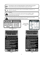
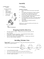
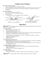
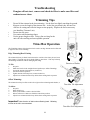
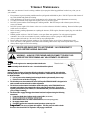
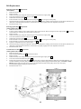
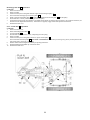
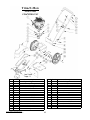
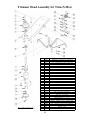
Visit us at www.swisherinc.com
OWNER’S
MANUAL
Trim-N-Mow
MODEL NO.
STARTING SERIAL # L113-135001
STS67522BS
STS67522BS-TSC
STP67522BS
STD67522BS
IMPORTANT
Read and follow all
Safety Precautions
and Instructions
before operating this
equipment.
Trim-N-Mow
Self-Propelled
Assembly
Operation
Service and
Adjustment
Repair Parts
Trim-Max
1602 CORPORATE DRIVE, WARRENSBURG MISSOURI 64093
PHONE 660-747-8183 FAX 660-747-8650
19046 REV 13-135
Made In The
USA
LIMITED WARRANTY
The manufacturer’s warranty to the original consumer purchaser is: This product is free from defects in
materials and workmanship for a period of two (2) years from the date of purchase by the original consumer
purchaser. We will repair or replace, at our discretion, parts found to be defective due to materials or
workmanship. This warranty is subject to the following limitations and exclusions:
1) Engine Warranty
All engines utilized on our products have a separate warranty extended
to them by the individual engine manufacturer. Any engine service
difficulty is the responsibility of the engine manufacturer and in no way
is Swisher or its agents responsible for the engine warranty. The Briggs
& Stratton Engine Service Hot Line is 1-800-233-3723.
2) Commercial Use
This product is not intended for commercial use and carries no
commercial warranty.
3) Limitation
This warranty applies only to products which have been properly
assembled, adjusted, and operated in accordance with the instructions
contained within this manual. This warranty does not apply to any
product of Swisher that has been subject to alteration, misuse, abuse,
improper assembly or installation, shipping damage, or to normal wear
of the product.
4) Exclusions
Excluded from this warranty are normal wear, normal adjustments, and
normal maintenance.
In the event you have a claim under this warranty, you must return the product to an authorized
service dealer. All transportation charges, damage, or loss incurred during transportation of parts
submitted for replacement or repair under this warranty shall be borne by the purchaser. Should
you have any questions concerning this warranty, please contact us toll-free at 1-800-222-8183.
The model number, serial number, date of purchase, and the name of the authorized Swisher dealer
from whom you purchased the mower will be needed before any warranty claim can be processed.
THIS WARRANTY DOES NOT APPLY TO ANY INCIDENTAL OR CONSEQUENTIAL
DAMAGES AND ANY IMPLIED WARRANTIES ARE LIMITED TO THE SAME TIME
PERIODS STATED HEREIN FOR ALL EXPRESSED WARRANTIES. Some states do not
allow the limitation of consequential damages or limitations on how long an implied warranty may
last, so the above limitations or exclusions may not apply to you. This warranty gives you specific
legal rights and you may have other rights, which vary from state-to-state. This is a limited
warranty as defined by the Magnuson-Moss Act of 1975.
2
Safety Instructions
This Safety Alert Symbol indicates important messages in this
manual. When you see this symbol, carefully read the message that
follows and be alert to the possibility of personal injury.
•
•
•
•
•
•
•
•
•
•
•
•
•
•
•
•
•
•
•
•
•
Read, understand and follow all instructions in the manual and on the trimmer
before starting.
Read this manual carefully. Become familiar with the controls and how to
operate the unit properly.
Only allow responsible adults, who are familiar with the instructions, to
operate the unit.
Clear the area of objects such as rocks, toys, etc. that could be thrown by the
unit.
Be sure the area is clear of other people before trimming. Stop the unit if
anyone enters the area.
Be aware of the direction of the trimmer discharge and do not direct it at
anyone. Do not direct trimmer discharge at breakable objects, such as
windows, etc.
Do not operate trimmer without all guards and shields in place.
Never leave the machine running unattended.
Trim only in daylight or good artificial light.
Do not operate the trimmer while under the influence of alcohol or drugs.
Watch for traffic when operating near roadways.
Use the trimmer as the manufacturer intended and as described in the
manual.
Do not operate trimmer if it has been dropped or damaged in any manner.
Always have the damage repaired before operating.
Always wear safety glasses or eye shields when using the trimmer.
Dress properly. Do not operate the trimmer when barefoot or wearing open
sandals. Wear only solid shoes for good traction when trimming. Wear long
sleeved shirts or jackets, also long pants. Do not trim in shorts.
Keep your eyes and mind on your trimmer and the area being trimmed. Do
not let other interests distract you.
Do not put hands and feet near or under rotating parts.
Before cleaning, inspecting or repairing your trimmer, stop the engine and
disconnect the spark plug wire and keep it away from the spark plug to
prevent accidental starting.
Do not operate the trimmer if it vibrates abnormally. Excessive vibration is a
sign of damage. Stop the engine and safely check for damage and repair as
required.
Do not operate the trimmer in wet grass, where good footing may not be
possible. Walk, never run.
Stop the trimmer when crossing gravel drives, etc.
3
Slope Operation
Slopes are a major factor related to loss of control and slip accidents,
which can result in severe injury. All slopes require extra caution. If you
feel uneasy on it do not trim it.
•
•
•
•
•
•
DO: Trim across the face of a slope and not up and down.
DO: Remove objects such as rocks, tree limbs, etc.
DO: Watch for holes, ruts or bumps. Tall grass can hide obstacles.
DO NOT: Mow near drop-offs, ditches or embankments. The operator could
lose footing or balance.
DO NOT: Trim excessively steep slopes.
DO NOT: Trim on wet grass. Reduced footing could cause slipping.
Children
•
K eep children out of the area and under the watchful care of another
responsible adult.
B e alert and turn the m achine off if children enter the area.
B efore and when backing, look behind and down for sm all children.
N ever allow children to operate this m achine.
U se extra care when approaching blind corners, shrubs, trees or other objects
that m ay obstruct vision.
•
•
•
•
Service
•
•
•
•
•
•
•
•
•
•
•
•
Use extra care handling gasoline and other fuels. They are flammable and
vapors are explosive.
Use only an approved container.
Never remove gas cap or add fuel with the engine running.
Allow engine to cool before refueling. Do not smoke while refueling.
Never refuel the machine indoors.
Never store the machine or fuel container where there is an open flame, such
as a water heater.
Never run a machine inside a closed area.
Keep nuts and bolts tight and equipment in good condition.
Never tamper with safety devices.
Keep machine free of grass, leaves or other debris build up. Clean oil or fuel
spillage. Allow machine to cool before storing.
Stop and inspect the equipment if you strike an object. Repair if necessary
before restarting.
Never make repairs or adjustments with the engine running.
4
The operation of any mower can encounter foreign objects to be thrown into the eyes, resulting in
severe eye damage. Always wear certified safety glasses or wide-vision safety goggles over
spectacles before starting any cutting machine and while operating such a machine.
The operation of any mower produces sound waves that are damaging to the human ear. Ear
protection is recommended.
CAUTION!
Tragic accidents can occur if the operator is not alert to the presence of children. Children
are often attracted to the machine and the mowing activity. Never assume that children
will remain where you last saw them.
Do not operate the trimmer if it vibrates abnormally. Excessive vibration is a sign of damage.
Stop the engine and safely check for damage and repair as required.
Trimmer Head
Instruction Decal
OD68
Caution Notice Decal
OD67
Trim-Max Decal
OD64
Trim-N-Mow Decal
OD65
5
Assembly
Tools Required:
•
½” Wrench
Contents of Box:
•
Trimmer
Parts bag containing:
•
Manual
•
Engine manual
•
Safety goggles
•
Bottle of engine oil
•
Trimmer line
•
Hex wrench
Installation of handles:
1.
Remove loose fasteners from trimmer frame handle
holes.
2.
Pivot handles up and align holes in handle with holes
on trimmer frame. Install hardware removed in
previous step. Snug, but do not tighten bolts.
3a.
For Trim-N-Mow and Trim-Max, pivot upper handles
to fit the lower handles. Tighten knobs.
3b.
For Self-Propelled Trim-N-Mow, attach upper handle to
lower handle using knobs and fasteners provided with
lower handle.
4.
Adjust handles for comfortable operation.
5.
Tighten all bolts.
Handles may be adjusted up and down and in and out for
comfortable operation.
Handle Adjustment
Preparing Unit For First Use
•
•
•
Fill engine crankcase with oil. A bottle has been provided with this unit. DO
NOT OVERFILL.
Fill the engine fuel tank with gasoline. GASOLINE SHOULD BE ADDED
OUTSIDE IN A WELL-VENTILATED AREA.
Check to ensure string has been installed properly. A diagram is provided just
above the wheel for proper installation.
Installing Trimmer Line
Important! Use the proper length of line. Using a line too long for the unit will cause
stalling and unacceptable operation.
Use 18” Trimmer Line Part Number P3618
Step 1
•
•
•
•
Step 2
Loosely fold trimmer line in half.
Place loop of line against outside of loop on the trimmer head (Step 1).
Bring ends around and through the loop and over the cutter line loop (Step 2).
Pull ends to tighten loop (Step 3).
6
Step 3
Trimmer Line Positions
Trimmer line attachment positions:
•
Trimmer is equipped with 4 trimmer line attachment points.
•
When mowing with trimmer, the 4 trimmer line configuration is recommended for a more consistent, even cut.
•
When trimming tall or thick vegetation, the 2 trimmer line configuration is recommended for improved
performance.
To adjust cutting height:
1.
Loosen set screw using hex wrench provided.
2.
Slide cutting head up or down to desired cutting height.
3.
Tighten set screw.
4.
Any cutting height may be used with either trimmer line configuration.
Set Screw
2 Trimmer line Configuration
Shown set at High cutting height
4 Trimmer line Configuration
Shown set at Low cutting height
Operation
Important! To ensure proper operation, clean the engine and trimmer regularly. Remove any build up
of chaff from the top of the engine.
To start the trimmer:
1.
Remove any built up debris from engine.
2.
Move throttle control to “FAST”.
3.
Push primer button on engine as directed.
4.
Firmly grasp rope handle and pull out slowly until resistance is felt. Then pull back rapidly with a
full arm stroke. If engine fails to start after 3 pulls, repeat step 3.
5.
When engine starts, leave throttle control at “FAST”. Throttle control must be set in the fast
position for maximum performance.
6.
Engage trimming head.
7.
Begin trimming.
To engage/disengage trimmer head:
•
Engage: Bring control bail into contact with the upper handle and grip it together with the handle.
If trimmer head does not fully engage, see belt adjustment section.
•
Disengage: Release control bail. Trimmer head should stop within a few seconds. If it does not,
see belt adjustment section.
To engage/disengage transmission (Self-propelled version only):
•
Engage: Bring transmission engagement lever into contact with the upper handle and grip it
together with the handle.
•
Disengage: Release transmission engagement lever.
To stop the trimmer:
1.
Release the control bail.
2.
Move throttle control lever on engine to “SLOW” for a few seconds then move to “STOP”.
Important!
For safest operation, make sure debris is directed away from you and others.
7
Troubleshooting
•
If engine will not start, remove and check air filter to make sure filter and
carburetor are clean.
Trimming Tips
•
•
•
•
•
Do not lift the trimmer head when trimming. Let the head rest lightly touching the ground.
Keep an eye on the length of the trimmer line. As the line gets shorter they become less
effective at cutting and will take longer to trim properly. Replace the line as necessary
(see Installing Trimmer Line).
Do not trim wet grass.
Use caution when trimming slopes.
Use the proper length on line. Using a line too long for the
unit will cause stalling and unacceptable operation.
Trim-Max Operation
The Trim-Max trimmer is designed to also be used as an edge trimmer and to offset left
to right for easier close trimming.
Edge Trimming/Bevel Cutting
The trimmer disk may be tilted from horizontal to vertical so that it may be used as an
edge trimmer. The head may also be tilted slightly to trim closer. This may be handy
for trimming foundations without damaging the siding.
Direction of Debris
To Tilt:
1.
2.
3.
4.
5.
6.
Stop unit.
Make sure head is in the straight forward position (see Offset Trimming).
Loosen the trimmer tilt clamp lever (clockwise).
Tilt head to desired position.
Tighten trimmer tilt clamp lever (counter-clockwise).
Adjust lower trimmer shield to keep debris from coming back at operator.
Offset Trimming:
The trimmer head may be offset to the left or right to allow trimming under bushes, etc.
Trim-Max Tilt Adjustment
To Offset:
1.
2.
3.
4.
5.
Stop unit.
Raise offset lever.
Push or pull handles to achieve desired offset.
Release offset lever. Make sure head has locked into position.
Adjust lower trimmer shield to keep debris from coming back at operator.
Important! Note direction of debris when offsetting head. Offsetting
trimmer to the left is recommended.
Trim-Max Pivot Adjustment
8
Trimmer Maintenance
Make sure your trimmer is in safe working condition by keeping the following guidelines in mind every time you use
your trimmer.
•
•
•
•
•
•
•
•
•
•
Keep trimmer in good operating condition and keep all guards and shields in place. DO NOT operate this trimmer if
any of the shields and guards are missing.
Check all fasteners for secure fit to keep equipment in safe working order. Make adjustments as necessary.
To reduce fire hazards, keep engine free of grass, leaves or excessive grease.
DO NOT operate trimmer with a damaged or missing muffler. DO NOT tamper with exhaust system; this may
cause a fire hazard.
DO NOT operate engine if air cleaner or the cover over the carburetor air intake is missing. Removal of these parts
could create a fire hazard.
Before cleaning, making adjustments or repairing the trimmer, STOP engine, disconnect spark plug wire and allow
engine to cool.
Handle gasoline with care. DO NOT smoke or use open flame near gasoline. Use only approved gasoline
containers. Never fuel or run trimmer in poorly ventilated areas, such as a garage or utility building.
Always replace fuel tank cap. Be sure to clean up any spilled gasoline.
Do not change the engine governor settings or over-speed the engine; severe injury or damage may result.
Never store mower with gasoline in the tank inside a building where fumes may reach an open flame or spark.
Always allow engine to cool before storing
NEVER ADD GASOLINE TO A HOT ENGINE – ALLOW ENGINE TO
COOL BEFORE ADDING GASOLINE.
WARNING – ALWAYS STOP ENGINE AND DISCONNECT SPARK PLUG
WIRE BEFORE PERFORMING ANY ADJUSTMENTS OR SERVICE.
Engine
• Refer to the engine service manual provided with this unit.
Thumb wheel
Belts
• Occasionally check the belt for wear. A worn belt should be replaced.
Belt Adjustment
During the first few hours of operation all belts go through a “break-in period” after which the
belts may need to be adjusted using the following instructions. Indications that the belts need to
be adjusted include:
• Loss of power at the trimming head causing the head to spin unusually slow or stop.
• Excessive wear on belt due to slipping.
• The belt that powers the transmission on the Self-Propelled TRIM-N-MOW is designed to be
under constant tension and needs no further adjustment.
• The belt between the trimmer head and the double idler pulley on the TRIM-MAX has an
automatic belt tightener that automatically adjusts when the head is tilted. If you do not
regularly tilt the head on your trimmer, it is recommended that you loosen the head twice a
year (see Edge Trimming).
• The belts used to engage/disengage the trimmer head can be adjusted using the following
instructions:
1. Locate the thumb wheel adjuster on the control cable (see illustration).
2. Released control bail to disengage trimmer head.
3. Rotate thumb wheel a few turns counterclockwise (from normal operating position).
4. Re-engage trimmer head.
5. If trimmer head has not returned to normal operation, repeat steps 2-4.
Important! Do not over tighten cable adjuster. This may cause the cable to break.
Excessive force should NOT be required to fully engage control bail.
9
Belt Replacement
Head Engagement Belt A Replacement
(Trim-N-Mow)
1.
Remove front belt cover.
2.
Remove old belt.
3.
Install new belt by first routing belt under the engine and around lower engine pulley I .
4.
Then route belt between two idler pulleys as shown F .
5.
Install belt around front pulley B .
6.
Ensure that belt is correctly installed between the belt guides C and in the grove of each pulley.
7.
If belt tension had previously been adjusted, reset thumb wheel adjuster by rotating wheel clockwise as far as adjuster will allow (see
illustration in belt adjustment instructions). If head does not properly engage refer to belt adjustment instructions.
8.
Reinstall front belt cover.
Head Engagement Belt A Replacement
(Self-Propelled Trim-N-Mow)
1.
Remove front belt cover.
2.
Loosen or remove fasteners used to attach engine to allow engine to shift. Slide or tilt engine so lower engine pulley I moves away
from transmission, creating a gap to allow belt to be removed.
3.
Remove old belt.
4.
Install new belt by first routing belt under the engine and around lower engine pulley I .
5.
Then route belt between two idler pulleys as shown F .
6.
Install belt around front pulley B .
7.
Ensure that belt is correctly installed between the belt guides C and in the grove of each pulley.
8.
Ensure that belt is over the top of the transmission axle E .
9.
Tighten or reinstall fasteners use to attach engine.
10. If belt tension had previously been adjusted, reset thumb wheel adjuster by rotating wheel clockwise as far as adjuster will allow (see
illustration in belt adjustment instructions). If head does not properly engage refer to belt adjustment instructions.
11. Reinstall front belt cover.
Transmission Power Belt H Replacement
(Self-Propelled Trim-N-Mow)
1.
Remove front belt cover.
2.
Remove Head Engagement Belt A per instructions above.
3.
Remove old belt.
4.
Install new belt by first routing belt under the engine and around upper engine pulley J .
5.
Then route belt around transmission pulley D .
6.
Finally route belt around rear idler pulley G . The idler pulley is spring loaded, making it difficult to finish belt installation. To
ease belt installation push idler pulley toward transmission pulley while wrapping belt around idler pulley. CAUTION – Pinch
Hazard: Ensure that you do not get any part of your body between the belt and the pulleys as this may cause injury.
7.
Reinstall Head Engagement Belt per instructions above.
8.
Reinstall front belt cover.
10
Head Engagement Belt Z Replacement
(Trim-Max)
1.
Remove front belt cover.
2.
Remove old belt.
3.
Install new belt by first routing belt under the engine and around engine pulley Y .
4.
Then route belt around upper power transfer pulley U .
5.
Finally route belt around idler pulley V . Ensure belt is routed between the belt guide W and idler pulley.
6.
Ensure that belt is correctly installed in the grove of each pulley.
7.
If belt tension had previously been adjusted, reset thumb wheel adjuster by rotating wheel clockwise as far as adjuster will allow (see
illustration in belt adjustment instructions). If head does not properly engage refer to belt adjustment instructions.
8.
Reinstall front belt cover.
Power Transfer Belt S Replacement
(Trim-Max)
1.
Remove front belt cover.
2.
Remove Head Engagement Belt Z .
3.
Loosen tilt handle X .
4.
Push trimmer head toward back of unit, compressing tensioner spring.
5.
Remove old belt.
6.
Install new belt by first routing belt around lower power transfer pulley T .
Then route belt around front pulley R . CAUTION – Pinch Hazard: Ensure that you do not get any part of your body between the
belt and the pulleys as this may cause injury.
8.
Release trimmer head and tighten tilt handle per operating instructions.
9.
Reinstall Head Engagement Belt per instructions above.
10. Reinstall front belt cover.
11
Trim-N-Mow
STS67522BS
STS67522BS-TSC
See Detail
Page 13
Item #
1
2
3
4
5
6
7
8
9
10
11
12
13
14
15
16
Part #
Description
N/A
Engine - Briggs & Stratton
NB170
Nut - Serrated Flange 5/16-18
NB253 Bolt - Serrated Flange, 5/16-18 X 1 1/4
2063
Pulley - Engine
NB607
Washer - SP Bellville
NB238N
Bolt - HHC 3/8-24 X 1
2019
Guard - Belt
26X249
Screw - .312-18 X .75
NB622 Bolt - Serrated Flange, 5/16-18 X 2 1/4
19006
Cable - Control, Trimmer
2030
Knob - Black Plastic
NB275
Washer - SAE Flat 5/16
19005
Handle - Bail
10578*
Handle - Upper
NB218
Bolt - 1/4-20 X 2 HCC GR5 ZY
NB180
Nut - Nyloc 1/4-20
When ordering replacement parts
* USE PAINT CODE: TK=BLACK
Item #
17
18
19
20
21
22
23
24
25
26
27
28
29
30
31
12
Part #
Description
NB587
Bolt - Carriage, 5/16-18 X 1 3/4
10399*
Handle - Lower
NB596 Bolt - Serrated Flange, 5/16-18 X 3/4
2026*
Cover - Rear
2002K
Wheel - 14"
NB132
Bolt -1/2-13 X 4
2005*
Base - Upper Motor
NB281
Nut - Nyloc 1/2-13
2106*
Plate - Axle
TR150W
Washer - .531 X 1 1/2 X .062
NB118
Nut - Jam, 1/2-13
NB555
Washer - USS Flat, 1/2
19034
Belt - 60", Trimmer
2006*
Base - Lower Motor
19004
Shield - Rubber
Trimmer Head Assembly for Trim-N-Mow
When ordering replacement parts
* USE PAINT CODE: TK=BLACK
ITEM # PART #
1
18999*
2
NB138
3
NB170
4
NB595
5
2049
6
NB149
7
B985/8
8
B98
9
19009
10
NB560
11
19011
12
712127
13
19010
14
19002*
15
NB180
16
NB779
17
024865
18
19012*
19
10501
20
NB107
21
T30V
22
NB174
23
NB272
24
19014*
25
NB181
26
B27
27
NB501
28
NB579
29
T30F
30
NB280
31
16823
32
2042
33
26X249
13
DESCRIPTION
Weldment - Trimmer Neck, Standard
Bolt - 5/16-18 X 2 1/2 HCC GR5 ZY
Nut - Serr Flange 5/16-18 ZY Case Hrd
Nut - Lock Jam, 5/8-11 2 Way
Pulley - Blade 4.5"
Washer - 5/8 ID X 1 OD 14 GA ZY
Bearing - Trimmer
Bearing - Blade
Shaft - Cutting Head, Standard
Bolt - 1/4-20 X 1 1/4 HCC GR5 ZY
Hub - Cutting Head, PM
Set Screw, 1/4-20 X .50, CP
Guard - Shaft, Trimmer
Weldment - Cutting Head Disc
Nut - Nyloc 1/4-20
Nut - Serr Flange, Hex ZY 3/8-16
1/2" SAE Flat Washer; ZP
Cutting Guide - Trimmer
3/8 X 1-1/4 Carriage Bolt
Bolt - 3/8-16 X 1 1/2 HCC GR5 ZY
Pulley - Idler Clutch, 2 3/4 OD
Nut - Jam 3/8-16 ZY Grade 2
Washer - SAE Flat 3/8 ZY Carbon Steel
Idler Arm - STP Trimmer
Nut - Nyloc 5/16-18 ZY
Idler Pulley OD-2.16", ID-3/8"
Bolt - 5/16-18 X 1 HCC GR5 ZY
Washer - Fender, 5/16 X 1 1/4 OD ZY GR2
Finger for Belt Release
Nut - 2 Way Lock 3/8-16 ZY & Wax Gr A
Bushing - Shoulder 3/8, ZT60
Guard - String
Screw - .312-18 X .75
Trim-N-Mow
Self-Propelled
STP67522BS
See Detail
Page 15
See Detail
Page 13
Item #
1
2
3
4
5
6
7
8
9
10
11
12
13
Part #
N/A
NB170
NB253
19018
NB607
NB238N
2019
26X249
9030
NB622
19027
NB180
2034B
Description
Engine - Briggs & Stratton
Nut - Serrated Flange 5/16-18
Bolt - Serrated Flange, 5/16-18 X 1 1/4
Pulley - Double Drive, Trimmer
Washer - SP Bellville
Bolt - HHC 3/8-24 X 1
Guard - Belt
Screw - .312-18 X .75
Key Stock - 3/16 X 1
Bolt - Serrated Flange, 5/16-18 X 2 1/4
Lever - Transmission Engagement
Nut - Nyloc 1/4-20
Cable - Transmission Control, Trimmer
When ordering replacement parts
* USE PAINT CODE: TK=BLACK
14
Item #
14
15
16
17
18
19
20
21
22
23
24
25
26
Part #
19006
2030
NB275
19005
19017*
NB218
NB587
10399*
NB596
19016*
19034
2006*
19004
Description
Cable - Control, Trimmer
Knob - Black Plastic
Washer - SAE Flat 5/16
Bail - Trimmer
Handle - Top, SP Trimmer
Bolt - 1/4-20 X 2 HCC GR5 ZY
Bolt - Carriage, 5/16-18 X 1 3/4
Handle - Lower
Bolt - Serrated Flange, 5/16-18 X 3/4
Cover - Rear, SP Trimmer
Belt - 60", Trimmer
Base - Lower Motor
Shield - Rubber
Drive Train Assembly for Trim-N-Mow Self-Propelled
ITEM #
1
2
3
4
5
6
7
8
9
10
11
12
13
14
15
16
17
18
19
20
21
22
23
24
25
26
27
28
29
30
31
32
33
34
35
PART #
19015*
10197
19019
10216
NB170
NB604
4005
NB182
NB302
T30V
NB174
19024*
NB272
7821
NB280
19020
19025
26X249
19087
NB501
NB579
16823
19023*
19052
NB126
19036
19022
19035
19021
19044
MWB
19045***
19026**
7841Z
NB555
DESCRIPTION
Motor Base - Upper, STP Trimmer
Bolt - Carriage 5/16-18X1 GR5 ZY
Bearing - 1/2" Flange Mounted
Bolt - Carriage 5/16-18X3/4 GR5 ZY
Nut - Serr Flange 5/16-18 ZY
Bolt - 3/8-16 X 1 GR5 ZY
Bearing - Side Flange
Nut - Nyloc 3/8-16 ZY
Bolt - 3/8-16 X 1 3/4 HCC GR5 ZY
Pulley - Idler Clutch, 2 3/4 OD
Nut - Jam 3/8-16 ZY Grade 2
Idler Arm - Transmission
Washer - SAE Flat 3/8 ZY
Latch Spring
Nut - 2 Way Lock 3/8-16 ZY
Transmission - String Trimmer
Axle - Self-Propelled Trimmer
SCREW - .312-18 x .75
Guard - Chain; Trimmer
Bolt - 5/16-18 X 1 HCC GR5 ZY
Washer - Fender, 5/16 X 1 1/4 OD ZY
Bushing - Shoulder 3/8, ZT60
Bracket - Idler Arm, SP Trimmer
Belt - 24", SP Trimmer
Pin - Cotter, 1/8 X 1
Pin - Cotter, 3/16 X 3; ZP
Sprocket - No. 35, 60 Teeth; 1/2" Bore
Pin - Cotter, 1/8 X 1-1/2; ZP
Sprocket - No. 35, 10 Teeth; 1/2" Bore
Chain - ANSI #35, 70 Link Loop
Bearing - Wheel, 1 1/8"OD X 1/2"ID
Clutch - Wheel, 1.125 OD X 0.5 ID
Wheel - 14", 1/2" Bearings; Trimmer
Bushing - Bell Crank
Washer - USS Flat, 1/2 ZY
When ordering replacement parts
* Use paint code: TK=Black
** Wheels include two bearings. Use part # MWB when replacing bearings only.
Note: Optional wheel kits are available that include the bearings and wheel clutch
installed. Order part # 19085 for left wheel kit and part # 19086 for right wheel kit.
*** Wheel clutch must be installed in the correct orientation in order to operate
properly. Wheel clutch is installed correctly when wheels spin freely while
trimmer is moving forward without the engine running (wheels will have resistance
when trimmer is moving backward). One of the wheel bearings may need to be
removed prior to installing the wheel clutch. The wheel clutch has an arrow on the
side to indicate the “free-wheel” direction. Ensure clutch is orientated so the freewheel direction corresponds to direction the wheel will rotate while trimmer is
moving forward and press the clutch into the center of the wheel (interference fit).
Then replace the wheel bearing and install the wheel on the axle. Caution: Ensure
both wheel bearings remain fully seated in wheel during wheel installation
and operation. Failure to do so may cause damage to wheel clutch.
Arrow on clutch shows
direction wheel spins
freely when installed.
15
Trim-Max
STD67522BS
SEE DETAIL
PAGE 17
Item #
1
2
3
4
5
6
7
8
9
10
11
12
13
14
15
16
17
18
19
20
21
22
Part #
N/A
19028*
NB253
NB170
9030
NB622
7323
NB607
NB238N
2119
NB252
19074
19053
NB596
2006*
NB177
19004
26X249
NB182
10578*
19005
NB180
Description
Briggs & Stratton Engine
Spacer - 1.125 OD X .885 ID X 1
Bolt - Serr Flange, 5/16-18 X1 1/4ZY
Nut - Serrated Flange 5/16-18
Key Stock - 3/16 X 1
Bolt - Serrated Flange 5/16-18X2 1/4
Pulley - Engine
Washer - SP Bellville
Bolt - HHC 3/8-24 X 1
Guard - Belt
Bolt - Serr Flange, 5/16-18 X 1/2 ZY
Belt - 45", DeluxeTrimmer
Belt - 26", Deluxe Trimmer
Bolt - Serrated Flange 5/16-18 X 3/4
Base - Lower Motor
Washer - Mach 1/2
Shield - Rubber
Screw - .312-18 X .75
Nut - Nyloc 3/8-16 ZY
Handle - Upper
Bail - Trimmer
Nut - Nyloc 1/4-20
When ordering replacement parts
* USE PAINT CODE: TK=BLACK
16
Item #
23
24
25
26
27
28
29
30
31
32
33
34
35
36
37
38
39
40
41
42
43
Part #
NB218
2030
NB275
NB587
19006
10399*
2040*
2077
2069
19059*
NB501
NB126
B99S
10004
T2PB
19058*
14416
2116
MWB
2003K**
2073*
Description
Bolt - 1/4-20 X 2 HCC GR5 ZY
Knob - Black Plastic
Washer - SAE Flat 5/16
Bolt - Carriage 5/16-18 X 1 3/4
Cable - Control, Trimmer
Handle - Lower
Stop - Pivot
Pivot - Handle Grip
Spring - Deluxe Trimmer
Cover - Rear, Deluxe Trimmer
Bolt - 5/16-18 X 1
Pin - Cotter, 1/8 X 1
Spacer
Spring - Conical
Bushing - Plastic
Motor Base - Upper, Dlx Trimmer
Axle - Trimmer; YZ
Strip - Wear
Bearing - Wheel, 1 1/8"OD X 1/2"ID
Wheel - 16", 1/2" ID Bearing, Blk
Plate - Pivot Weldment
** Wheels include two bearings. Use part #
MWB when replacing bearings only.
Trimmer Head Assembly for Trim-Max
When ordering replacement parts
*Use paint code: TK=Black
**Items 26-31 can be purchased
collectively by ordering part # 2076.
ITEM #
1
2
3
4
5
6
7
8
9
10
11
12
13
14
15
16
17
18
19
20
21
22
23
24
25
26
27
28
29
30
31
32
33
34
35
36
37
38
39
40
41
42
43
44
45
46
47
17
PART #
NB595
2049
NB149
B985- 8
2033
19030*
B98
19009
NB560
19011
712127
19010
19002*
NB180
NB779
024865
19012*
10501
NB280
NB272
19033
2827
19032*
10177
19029*
NB110**
2043**
NB275**
2084**
2030**
2042**
NB107
T30V
NB174
NB272
T30F
B19BLAC
2103A
2075
NB210Z
2068
NB170
NB594
NB181
NB173
2083
2078
DESCRIPTION
Nut - Lock Jam, 5/8- 11 2 Way
Pulley - Blade, 4.5"
Washer - 5/8 ID X 1 OD 14 GA ZY
Bearing - Trimmer
Spring - Compression
Weldment - Head, Punched; Dlx Trimmer
Bearing - Blade
Shaft - Cutting Head, Standard
Bolt - 1/4- 20 X 1 1/4 HCC GR5 ZY
Hub - Cutting Head, PM
Set Screw, 1/4- 20 X .50, CP
Guard - Shaft, Trimmer
Weldment - Cutting Head Disc
Nut - Nyloc 1/4- 20
Nut - Serr Flange, Hex ZY 3/8- 16
Washer - 1/2 SAE Flat ZP
Cutting Guide - Trimmer
Bolt - Carriage 3/8- 16 X 1 1/4 GR5 ZY
Nut - 2 Way Lock 3/8- 16 ZY
Washer - SAE Flat 3/8 ZY Carbon Steel
Pulley - Double Idler, Dlx Trimmer
Pivot - Bushing
Idler Arm - Deluxe Trimmer
Washer - Fender 3/8 X 1.5
Weldment - Slide, Deluxe Trimmer
Bolt - Carriage, 5/16- 18 X 2 1/4 Gr 2 ZY
Clamp - String Shield
Washer - SAE Flat 5/16 ZY
Spacer - String Shield Clamp
Knob - Black Plastic
Guard - String
Bolt - 3/8- 16 X 1 1/2 HCC GR5 ZY
Pulley - Idler Clutch, 2 3/4 OD
Nut - Jam 3/8- 16 ZY
Washer - SAE Flat 3/8 ZY
Finger for Belt Release
Knob - Shift, Blac k
Pivot - Handle
U- Bolt; Tilt - Clamp (Knurled)
Nut - 5/16- 18 HNC GR2 ZY
Cap - Plastic, 1 1/4"
Nut - Serr Flange 5/16- 18 ZY Case Hrd
Nut - Coupling 5/16 - 18 x 1 3/4
Nut - Nyloc 5/16- 18 ZY
Nut - Jam 5/16- 18 ZY
Handle - Bent ZY
Grip - Tilt Handle; Yellow
NOTES:
______________________________________________________________________
______________________________________________________________________
______________________________________________________________________
______________________________________________________________________
______________________________________________________________________
______________________________________________________________________
______________________________________________________________________
______________________________________________________________________
______________________________________________________________________
______________________________________________________________________
______________________________________________________________________
______________________________________________________________________
______________________________________________________________________
______________________________________________________________________
______________________________________________________________________
______________________________________________________________________
______________________________________________________________________
______________________________________________________________________
______________________________________________________________________
______________________________________________________________________
______________________________________________________________________
______________________________________________________________________
______________________________________________________________________
______________________________________________________________________
______________________________________________________________________
______________________________________________________________________
______________________________________________________________________
______________________________________________________________________
______________________________________________________________________
______________________________________________________________________
______________________________________________________________________
______________________________________________________________________
______________________________________________________________________
18
NOTES:
______________________________________________________________________
______________________________________________________________________
______________________________________________________________________
______________________________________________________________________
______________________________________________________________________
______________________________________________________________________
______________________________________________________________________
______________________________________________________________________
______________________________________________________________________
______________________________________________________________________
______________________________________________________________________
______________________________________________________________________
______________________________________________________________________
______________________________________________________________________
______________________________________________________________________
______________________________________________________________________
______________________________________________________________________
______________________________________________________________________
______________________________________________________________________
______________________________________________________________________
______________________________________________________________________
______________________________________________________________________
______________________________________________________________________
______________________________________________________________________
______________________________________________________________________
______________________________________________________________________
______________________________________________________________________
______________________________________________________________________
______________________________________________________________________
______________________________________________________________________
______________________________________________________________________
______________________________________________________________________
______________________________________________________________________
19
Visit us at: www.swisherinc.com
OWNER’S
MANUAL
MODEL NO.
Each trimmer has its own model number. Each engine has its
own model number. The model number for the trimmer will be
found on the left hand side of the motor base. The model
number for the engine will be found on the top of the blower
fan housing.
All trimmer parts listed herein may be ordered directly from
Swisher or your nearest Swisher dealer.
All engine parts may be ordered from the nearest dealer of the
engine supplied with your mower.
STS67522BS
STS67522BS-TSC
STP67522BS
STD67522BS
WHEN ORDERING PARTS, PLEASE HAVE THE
FOLLOWING INFORMATION AVAILABLE:
*
*
*
*
PRODUCT – TRIMMER
SERIAL NUMBER - _______________
MODEL NUMBER - _______________
ENGINE MODEL NUMBER - _______________
TYPE - _______________
* PART NUMBER WITH PAINT CODE
* PART DESCRIPTION
TELEPHONE - 1-800-222-8183
FAX - 1-660-747-8650
SWISHER
1602 CORPORATE DRIVE
WARRENSBURG, MO 64093
Changing your landscape since 1945.
20