1
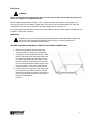
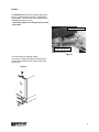
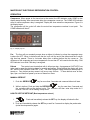
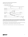
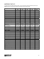
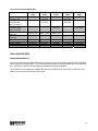
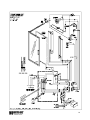
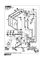
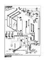
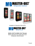
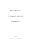
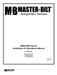
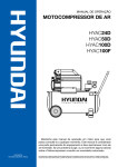
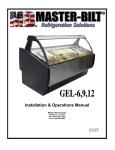
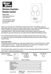
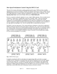
BLG/TLG Series
Bottom Mount Glass Door Merchandisers
2005 “K” Version with Dixell controller
Installation & Operations Manual
Master-Bilt Products
908 Highway 15 North
New Albany, MS 38652
Service Phone: 800-684-8988
PN 303-91000
Rev:8-20-05
Rev:8-23-06
2
TABLE OF CONTENTS
INTRODUCTION………………………………….……………………………………………………………………4
STORE CONDITIONS…………………………….……………….…..…………………………………………….. 4
WARNING LABELS AND SAFETY INSTRUCTIONS………..…..……………………………………………… 5
PRE-INSTALLATION INSTRUCTIONS………………………..…..………………………………….…………… 6
Inspection for Shipping Damage…………………………………………………………….……………... 6
INSTALLATION INSTRUCTIONS………………………………………………………………………………….. 6
General Instructions…………………………………………………………………………………………. 6
Mechanical ..…………………………………………………………………………………………………..6
Electrical…………...…………………………………………………………………………………………..7
Leg and Condensate Pan Installation..……………………………………………………………………. 7
Doors ..…………....………………………………………………………………………………………….. 8
ELECTRONIC REFRIGERATION CONTROL (DIXELL RX60C)…………………………………………….… 9
Programming……………………………………………………………………………………………..…. 9
List of Parameters………………………………………………………………………………………..….10
SENSOR PROBE ………………………………………………………………………………….………………. 11
CABINET COMPONENT AMP DRAW………………………………………………………………………………11
TEMPERATURE SENSOR, DEFROST HEATER AND FAN MOTOR REPLACEMENT…………………… .12
FINAL CHECK LIST…………………………………………………………………………………….………….… 13
SERVICE INSTRUCTIONS ………………………………………………………………………………………... 13
MASTER-BILT PART NUMBERS …………………………………………………………………………………. 14
ACCESSORIES
…………………………………………………………………………………………………….15
SALE AND DISPOSAL ……………………………………………………………………………………………..15
WIRING DIAGRAMS BLG/TLG………………………………………….……………………….………… …...16-19
3
INTRODUCTION
Thank you for purchasing a Master-Bilt cabinet. This manual contains important instructions for installing,
using, and servicing a Master-Bilt BLG/TLG case. A parts list is included with this manual. Read all these
documents carefully before installing or servicing your equipment.
STORE CONDITIONS
The Master-Bilt BLG/TLG cases are designed to operate in the controlled environment of an air-conditioned
store. The store temperature should be at or below 75°F and a relative humidity of 55% or less. At higher
temperature or humidity conditions, the performance of these cases may be affected and the capacity
diminished.
The Master-Bilt BLG/TLG should not be positioned where it is directly exposed to rays of sun or near a direct
source of radiant heat or airflow. This will adversely affect the case and will result in poor performance.
If this case is to be located against a wall, there should be at least 6” space between the wall and the back of
the case. This space will allow for the circulation of air behind the case, which will prevent condensation on the
exterior surfaces.
NOTICE
Read this manual before installing your cabinet. Keep the manual and refer to it before
doing any service on the equipment. Failure to do so could result in personal injury or damage to the
cabinet.
DANGER
Improper or faulty hook-up of electrical components on the refrigeration units can result in severe
injury or death.
All electrical wiring hook-ups must be done in accordance with all applicable local, regional or national
standards.
NOTICE
Installation and service of the refrigeration and electrical components of the cabinet must be
performed by a refrigeration mechanic and/or a licensed electrician.
The portions of this manual covering refrigeration and electrical components contain technical instructions
intended only for persons qualified to perform refrigeration and electrical work.
This manual cannot cover every installation, use or service situation. If you need additional information, call or
write us:
Customer Service Department
Master-Bilt Products
Highway 15 North
New Albany, MS 38652
Phone 800-684-8988
Fax 866-882-7629
4
WARNING LABELS AND SAFETY INSTRUCTIONS
This symbol is the safety-alert symbol. When you see this symbol on your cabinet or in this
manual, be alert to the potential for personal injury or damage to your equipment.
Be sure you understand all safety messages and always follow recommended precautions and safe operating
practices.
NOTICE TO EMPLOYERS
You must make sure that everyone who installs, uses or services your cabinet is thoroughly familiar
with all safety information and procedures.
Important safety information is presented in this section and throughout the manual. The following signal
words are used in the warnings and safety messages:
DANGER:
Severe injury or death will occur if you ignore the message.
WARNING: Severe injury or death can occur if you ignore the message.
CAUTION: Minor injury or damage to your cabinet can occur if you ignore the message.
NOTICE:
This is important installation, operation or service information. If you ignore the
message, you may damage your cabinet.
The warning and safety labels shown throughout this manual are placed on your Master-Bilt Products
cabinet at the factory. Follow all warning label instructions. If any warning or safety labels become
lost or damaged, call your customer service department at 800-684-8988 for replacements.
CAUTION!
GROUND REQUIRED
FOR SAFE OPERATION
This label is located on top of the electrical control
label and on the wiring channel.
This label is attached to the cabinet power cord
on models with a power cord.
5
PRE-INSTALLATION INSTRUCTIONS
INSPECTION FOR SHIPPING DAMAGE
You are responsible for filing all freight claims with the delivering truck line. Inspect all cartons and crates for
damage as soon as they arrive. If damage is noted to shipping crates or cartons or if a shortage is found, note
this on the bill of lading (all copies) prior to signing.
If damage is discovered when the cabinet is uncrated, immediately call the delivering truck line and follow up
the call with a written report indicating concealed damage to your shipment. Ask for an immediate inspection of
your concealed damage item. Crating material must be retained to show the inspector from the truck line.
INSTALLATION INSTRUCTIONS
GENERAL INSTRUCTIONS
1. Be sure the equipment is properly installed by competent service people.
2. Keep the equipment clean and sanitary so it will meet your local sanitation codes. Clean the cabinet with a
mild detergent and water, then rinse.
3. Rotate your stock so that older stock does not accumulate. This is especially important for ice
cream. A "First-In, First-Out" rotation practice will keep the products in good salable condition.
4. Do not place product in the case when it is soft or partially thawed. Also, product should not be put in the
case for at least 6 hours after it is started.
5. Stock cases as quickly as possible, exposing only small quantities to store temperatures for short periods of
time.
6. When replacing burned out fluorescent tubes, be sure that the electrical power to the lighting circuit is
turned off.
NOTICE TO STORE OWNERS / MANAGERS
Moisture or liquid around or under the cabinet is a potential slip/fall hazard for persons walking by or
working in the general area of the cabinet. Any cabinet malfunction or housekeeping problem that
creates a slip/fall hazard around or under the cabinet should be corrected immediately.
If moisture or liquid is observed around or under a Master-Bilt cabinet, an immediate investigation should be
made by qualified personnel to determine the source of the moisture or liquid. The investigation should
determine if the cabinet is malfunctioning or if there is a drainpipe leaking.
MECHANICAL
Remove front grille and check refrigeration lines to see that they are free (not touching each other or
compressor). Spin condenser fan blade to see that it is free.
Remove cabinet from crate base and slide into location. Cabinet must be level from side to side and front to
back for correct draining of coil pan and for self-closing doors to operate correctly. Allow minimum of 4”
between back of cabinet and wall and between top of cabinet and ceiling for proper condensing unit air
circulation.
To comply with Sanitation requirements the cabinet must be mounted on legs (6” high min.) or casters or the
base must be sealed to the floor (BLG) with an N.S.F. listed silicone sealant.
6
ELECTRICAL
WARNING
Before servicing electrical components in the case or the doors or door frames make sure all power to
case is off. Always use a qualified technician.
Check voltage and amps drawn on (Page 17-20) to determine proper line and fuse or circuit breaker size.
Check power supply for low voltage. If voltage reads “230” with no load, and it drops below “207” when the
compressor tries to start, it is an indication of too small supply wiring or too long to run.
It is recommended that a separate circuit be run for each cabinet to prevent another appliance blowing the fuse
or breaker, causing loss of product.
IMPORTANT
Models (2 and 3 door low temp) are pre-wired internally with a 208-230V NEMA L14-20P plug
and should only be plugged into a NEMA L14-20P recepticle. See wiring diagrams on
page 19-21. The cabinet should be grounded.
LEG AND CONDENSATE PAN INSTALLATION FOR TOP MOUNT CABINETS ONLY
1. Screw legs into existing crate mounting holes.
2. Before moving cabinet into place, remove the
condensate pan from the top unit compartment.
3. Using the two screws supplied with the pan, attach
the pan to the back of the cabinet at the two holes
near the bottom of the plastic drain line. Be sure
pan is NOT located directly under cabinet. When
the pan is attached, feeds drain line into the open
hole in screen and clamp the heater conduit to the
back of the cabinet. Due to this condensate pan,
this case must be a minimum of 6” from the wall.
4. If cabinet must be located next to wall, the pan can
be located under the cabinet. When this is done,
steam will accumulate on the bottom of the cabinet
if there is not adequate ventilation, and rusting of
the bottom of the cabinet
will occur.
7
DOORS
The BLG/TLG cabinets have Anthony glass doors
that are equipped with a patented TorqueMaster™
hinge system. The doors are easily adjusted using
a flathead screwdriver (Fig.3).
* The tension needs to be checked and set when
first install.
Leveling Adjustment
Torque Adjustment
Figure 3
To remove the door shipping clamps,
remove the 4 shipping screws from the grill and
remove the screws from the clamps (Fig.4), and
replace grill.
Figure 4
8
MASTER-BILT ELECTRONIC REFRIGERATION CONTROL
OPERATION
Compressor When power is first turned on to the control, the LED indicator under COMP on the
display starts blinking. After one-minute delay the compressor comes on. The COMP LED indicator
stays on while compressor relay is energized. Display will show actual box temperature. Figure 4 is
the display layout.
The compressor will be cycled off when the actual box temperature reaches its set point. The
COMP indicator will be off.
Fig. 4 – Display Lay-out
Fan The fans will run constantly except when a defrost is initiated, or when the evaporator temp
o
is above the 30 F. When in defrost mode the fan is off until the end of the defrost and the 2 minute
drip time has passed. There is 4 minutes delay after a defrost before the fan comes on. The
o
difference of the evaporator and room temperature of more than 9 F will override the fan delay. FAN
LED indicator is on while FAN relay is energized.
Defrost
The control uses time defrost with 4 defrost per day. A programmed “HOT-KEY” has
to be used to re-set the defrost scheme for special applications. During defrost the display will show
dEF and the LED indicator under DEF in on. The control begins timing the defrost when power is
turned on. Four defrost per day means it will occur every 6 hours. To have defrost occur at 8am,
2pm, 8pm, and 2am then power up at one of these four times.
MANUAL DEFROST
1. Push this DEFROST
key for more than 2 seconds and a manual defrost will start.
2. While in defrost, Push and hold the DEFROST
key for more than 5 seconds and
the controller will end the defrost cycle. The controller will then enter drip mode for 2
minutes. The DEF led is flashing in drip mode.
HOW TO SEE THE SETPOINT (Box temperature cut-out)
Push and immediately release the SET key: the display will show the Set
point value;
2. Push and immediately release the SET key or wait for 5 seconds to display the probe value
(actual box temperature) again.
1.
9
HOW TO CHANGE THE SETPOINT
1. Push the SET key for more than 2 seconds to change the Set point value;
2. The value of the set point will be displayed and the LED under COMP starts blinking;
3. To change the Set value push the UP ▲ or DOWN▼ arrows within 10s.
To memorize the new set point value push the SET key again or wait 10s.
HOW TO CHANGE a parameter value
1. Enter the Programming mode by pressing the SET and DOWN ▼
keys for 3 seconds
(LEDs under DEF and COMP start blinking).
2. Select the required parameter by pushing the UP ▲ or DOWN▼ arrows
3. Press the “SET” key to display its value (now only the COMP LED is blinking)
4. Use “UP” or “DOWN” to change its value
5. To exit: Press SET + UP ▲ or wait 15s without pressing a key.
NOTE 1: The set value is stored even when the procedure is exited by waiting the time-out to expire.
NOTE 2: Master-Bilt’s SETPOINT is set at a recommended –10°F at the factory for low temperature(LT) and
o
+35 F for medium temperature(MT) application.
NOTE 3: To scroll down the parameters without changing them, press the DOWN button.
LIST OF PARAMETERS
Here is a list of the parameters the value of which can be changed in the programming mode, as
well as their ranges.
Parameter
Temperature Set
Point
Temperature
Differential
Maximum
Temperature
Alarm
Minimum
Temperature
Alarm
Temperature
Alarm Delay
Room Probe
display
Evaporator
Probe Display
Display
Symbol
Range
Master-Bilt’s
Setting
BLG
-16 to 5°F
-10°F or -15°F
Hy
1 to 255°F
10
ALU
230°F
15
ALL
-58°F
-25
0 to 255 min
30
Set
Description
When this temperature is
reached the compressor LED
will be off
Cut-out temperature is Set + Hy
Ald
dP1
dP2
10
ALARM SIGNALS
Message
Cause
Room probe failure
“P1”
Outputs
Compressor output time, 6 min on, 4 min off
“P2”
Evaporator probe failure
Defrost end is timed
“HA”
Maximum temperature alarm
Outputs unchanged.
“LA”
Minimum temperature alarm
Outputs unchanged.
NOTE:
Probe alarms “P1” and “P2” start some seconds after the fault in the related probe; they
automatically stop some seconds after the probe restarts normal operation. Check
connections before replacing the probe.
Temperature alarms “HA” and “LA” automatically stop as soon as the thermostat
temperature returns to normal values and when defrost starts.
ELECTRICAL CONNECTIONS
2
The controller is provided with screw terminal block to connect cables with a cross section up to 2,5 mm .
Before connecting cables make sure the power supply complies with the control’s requirements. Separate the
probe cables from the power supply cables, from the outputs and the power connections. Do not exceed the
maximum current allowed on each relay, in case of heavier loads use a suitable external relay.
PROBE CONNECTIONS
The probes shall be mounted with the bulb upwards to prevent damages due to casual liquid infiltration. It is
recommended to place the thermostat probe away from air streams to correctly measure the average room
temperature. Place the defrost termination probe among the evaporator fins in the coldest place, where most
ice is formed, far from heaters or from the warmest place during defrost, to prevent premature defrost
termination.
BLG/TLG CABINET COMPONENT AMP DRAW
ITEM
Coil Defrost Heater
Coil Defrost Heater
Condensate Heater
Condensate Heater
Door Frame Heater
Door
Door
Door
Door
Drain Heater
PART
NO.
17-09408
17-01311
201I130
17-09419
31-02602
31-02603
31-02604
31-02605
17-00404
VOLTAGE
AMPS AT AMPS AT
RATING
CABINET
208 VOLTS 230 VOLTS
230 V
BLG/TLG-48, 52
3.9
4.3
230 V
BLG/TLG-74, 80
6.3
7
230 V
BLG-48, 52, 74, 80
1.2
1.3
230 V
TLG-48, 52, 74, 80
1.2
1.3
115 V BLG/TLG-48, 52, 74, 80
.33 ea
.37 ea
120V
BLG/TLG-48, 74
.55 ea
.60 ea
120V
BLG/TLG-48
.55 ea
.60 ea
120V
BLG/TLG-52, 80
.76 ea
.84 ea
120V
BLG/TLG-52
.76 ea
.84 ea
115 V BLG/TLG-48, 52, 74, 80
0.05
0.06
VOLTAGE
ITEM
RATING
Coil Defrost Heater 17-09407 120 V
Condensate Heater A321-130 115 V
Condensate Heater 323I130
115 V
Door Frame Heater 17-09419 115 V
Door
31-02600
120V
Drain Heater
17-00404 115 V
PART
NO.
CABINET
BLG/TLG-27
BLG-27
TLG-27
BLG/TLG-27
BLG/TLG-27
BLG/TLG-27
AMPS AT AMPS AT
104 VOLTS 115 VOLTS
4.3
4.8
2.3
2.6
2.3
2.6
0.33
0.37
.81 ea
.90 ea
0.05
0.06
NOTES
Check Red or Black Leg
Check Red or Black Leg
Check Red or Black Leg
Check Red or Black Leg
Check Black Leg
Check Black Leg
Check Black Leg
Check Black Leg
Check Black Leg
Check Black Leg
NOTES
Check Black Leg
Check Black Leg
Check Black Leg
Check Black Leg
Check Black Leg
Check Black Leg
11
FINAL CHECK LIST
A.
Check operating pressures.
B.
Check electrical requirements of unit to supply voltage.
C.
Set temperature control for desired temperature range.
D.
Check sight glass for proper refrigerant charge, if provided.
E.
Check system for proper defrost settings and operation.
F.
Check condensing unit for vibrating or rubbing tubing. Dampen and clamp as required.
G.
All valves should be completely opened counter-clockwise.
H.
Check packing nuts on all service valves.
I.
Replace all service valve caps and latch unit covers.
J.
Check and set the door tension at the Torque Adjustment.
SERVICE INSTRUCTION
1. High head pressure and high back pressure:
A. Condenser coil clogged or restricted
B. Condenser fan motor defective.
C. Air discharge in rear of cabinet restricted.
2. Low back pressure and low head pressure:
A. Restriction in system.
B. Refrigerant undercharged.
C. Leak in system
3. Pressure normal – cabinet warm:
A. Coil blocked with frost (see #4).
B. Refrigerant undercharged.
C. Control set too warm.
4. Cabinet not cycling – coil blocked with frost:
A. Defective temperature controller.
B. Refrigerant overcharged.
C. Location too hot.
D. Condenser clogged.
E. Condenser fan motor defective.
F. Defrost heater not operating.
5. Copressor starts and runs – but cycles on overload:
A. Low voltage
B. Relay defective.
C. Overload defective.
D. High head pressure (see #1).
12
Temperature sensor, defrost heater and fan motor replacement
Before making any change, technician should:
1. Disconnect power to the cabinet
2. Remove screws from venturi and pull down
To change a temperature sensor (cabinet zone sensor or defrost termination sensor), simply disconnect the
sensor wires from the controller and replace the new sensor in the original position. Use plastic tie to tighten the
zone sensor. Insert the sensor for defrost termination firmly into the evaporator coil, in between the fins. Make
sure the sensor wires do not touch or are not close to any heater rods.
To change defrost heater – remove screws from drain pan and pull down – remove screws from coil mounting
straps – spring straps open – remove heater shield – pull heater out of slots in coil fins.
To change fan motor – disconnect fan motor leads – remove screws from fan guards and motor mounts.
13
MASTER-BILT PART LIST
The table below gives Master-Bilt part numbers. Use this chart when ordering replacement parts for your
BLG/TLG cabinets. Always Advise Cabinet Serial Number When Ordering Parts
Description
Ballast
Bulb
Bulb Holder Bottom
Bulb Holder Top
Bulb Shield Inner
Bulb Shield Outer
Coil Defrost Heater
Compressor
Compressor Contactor
Compressor Relay
Compressor Run Capacitor
Compressor Start Capacitor
Compressor Switch
Condensate Heater “T”
Condensate Heater
Electric, TLG
Condensate Heater, BLG
Electric (Optional)
Condenser Coil
Condenser Fan Blade
Condenser Fan Motor
Door Frame Heater
Door-L.H. (Black)
Door-R.H.
Drain Heater
Drier
Electronic Controller
Evaporator Coil
Evaporator Fan Blade
Evaporator Fan Guard
Evaporator Fan Motor
Expansion Valve
Female Door Plug
Female Plug
Front Control
Heater Safety Control
Leg (TLG only)
Leg Leveler
Light Switch
BLG/TLG27HD
23-01706
23-01689
23-00335
23-00336
23-01692
23-01462
17-09407
03-14799
19-13936
19-13118
17-00380
BLG/TLG48HD
23-01706
23-01689
23-00335
23-00336
23-01692
23-01464
17-09408
03-14968
19-13934
03-14980
03-14978
03-14979
19-13118
17-00421
BLG/TLG52HD
23-01706
23-01689
23-00335
23-00336
23-01692
23-01464
17-09408
03-14968
19-13934
03-14979
03-14978
03-14979
19-13118
17-00421
BLG/TLG74HD
23-01706
23-01689
23-00335
23-00336
23-01692
23-01464
17-01311
03-14973
19-13934
03-14977
03-14975
03-14976
19-13118
17-00421
BLG/TLG80HD
23-01706
23-01689
23-00335
23-00336
23-01692
23-01464
17-01311
03-14973
19-13934
03-14977
03-14975
03-14976
19-13118
17-00421
323I130
323I130
323I130
323I130
323I130
A321-130
17-00421
17-00421
17-00421
17-00421
07-13241
15-13093
13-00311
17-09419
31-02600
07-14009
15-13093
13-01283
17-09419
31-02602
31-02603
17-00404
09-09711
19-13918
07-13289
15-13106
25-01324
13-13182
09-09758
21-00568
21-00577
19-13897
19-01164
27-00558
27-00592
23-50793
07-14009
15-13093
13-01283
17-09419
31-02604
31-02605
17-00404
09-09711
19-13918
07-13289
15-13106
25-01324
13-13182
09-09758
21-00568
21-00577
19-13897
19-01164
27-00558
27-00592
23-50793
07-14009
15-13093
13-01283
17-09419
31-02602
07-14009
15-13093
13-01283
17-09419
31-02604
17-00404
09-09711
19-13918
07-13290
15-13106
25-01324
13-13182
09-09759
21-00568
21-00577
19-13897
19-01164
27-00558
27-00592
23-50793
17-00404
09-09711
19-13918
07-13290
15-13106
25-01324
13-13182
09-09759
21-00568
21-00577
19-13897
19-01164
27-00558
27-00592
23-50793
19-13932
19-01091
19-13932
19-01091
19-13932
19-01091
19-13932
19-01091
17-00404
09-09171
19-13918
07-13288
15-13106
25-01324
13-13181
09-09825
21-00568
21-00577
19-13897
19-01164
27-00558
27-00592
23-50793
Sight Glass
Temperature Sensor (2)
Terminal Block
19-13932
14
Accessories (Includes HD Models)
Description
Baskets (Cantilever)
20” X 22” X 5”
Baskets
(Conventional)
22”X 22-3/4”X 5”
Baskets
(Conventional)
24-3/4”X22”X5”
Casters (4) 3”
Diameter
Casters (6) 3”
Diameter
Legs 6”
Shelves (Cantilever)
Shelve, Bottom
Shelving Clips (4)
BLG/TLG27HD
BLG/TLG48HD
BLG/TLG52HD
BLG/TLG74HD
33-01458
33-01458
33-01419
33-01419
33-01376
A200-11140
A200-11170
33-01473
33-01402
33-01011
A200-11140
A200-11170
33-01474
33-01453
33-01011
BLG/TLG80HD
33-01376
A200-11140
A200-11170
33-01475
33-01448
33-01011
A212-11140
A212-11140
A212-11170
33-01474
33-01453
33-01011
A212-11170
33-01475
33-01448
33-01011
SALE AND DISPOSAL
OWNER RESPONSIBILITY
If you sell or give away your Master-Bilt cabinet you must make sure that all safety labels and the Installation Service Manual are included with it. If you need replacement labels or manuals, Master-Bilt will provide them
free. Contact the customer service department at Master-Bilt at (800) 684-8988.
The customer service department at Master-Bilt should be contacted at the time of sale or disposal of your
cabinet so records may be kept of its new location.
15
16
17
18
19
20