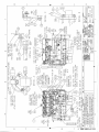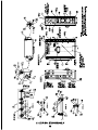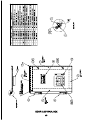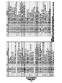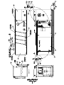
1
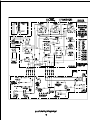
KLINGE CORPORATION
Address: 4075 East Market Street York, PA 17402-5100 USA
Telephone: 717.840.4500 Telefax: 717.840.4501
Manuals & Diagrams see – www.klingecorp.com
Service Parts see – www.reeferparts.com
MODEL NMG-115-10 & NMG-115-12
GENERATOR SET
SERVICE AND PARTS MANUAL
MANUFACTURED BY KLINGE CORPORATION
December 2011
Manual No. K35-05850-08-10
2
TABLE OF CONTENTS
SECTION ONE…………………………………………………………………….
Specification
9
SECTION TWO…………………………………………………………………...
Safety Precautions
13
SECTION THREE…………………………………………………………………
Engine Operation
Wiring Schematic……………………………………………………………………
17
SECTION FOUR…………………………………………………………………..
Maintenance & Component Information
23
SECTION FIVE…………………………………………………………………….
Trouble shouting
25
19
SECTION SIX……………………………………………………………………….. 29
Service Parts
MARATHON LIMA MAC SERVICE MANUAL
3
4
Serial Numbers Registration – Warrantee
The blue data plate machine serial number and the ISO container serial number should be
reported to [email protected] at the time of installation. In the event that the
installation date and which machine is on which container is not reported, the warrantee period
will default to 18 months from the date of manufacture. Failure to report the above could result
in the warrantee period being foreshortened.
Use of this Manual
By extension, this manual may be used for other combinations of the same equipment but one
would be better served by reference to the particular model, items, and variations. The model
number on all Klinge Corporation equipment may be found on the blue serial number data plate.
With the model number you may pull down and print out the whole or relevant sections of the
manual from the www.klingecorp.com /manuals download/ then model number. If the particular
model is not on the web page contact [email protected] or telephone
(USA) (1) 717 840 4500.
The use of this manual is intended for the safe operation of the equipment described. It is
therefore reasoned that persons who have the occasion to use this manual have a knowledge of
mechanical and electrical systems and components addressed by its' contents. However, efforts
have been made to enable persons less familiar with these systems to use this manual.
Suggestions as to improvement in content and format are welcome and should be addressed to
[email protected] . Corrections and improvements will be included on dated
revisions - the latest of which will be available on the web page.
5
6
PRE-TRIP CHECKOUT FORM
1. Inspect generator set for damage, missing parts, or loose mounting bolts.
2. Check fuel level. Use ASTM D975-96 #2-D or #1-D in cold weather;
DIN EN 590; BS 2869; NATO Code F-54 / F-34 / F-44 and XF 63 or equivalents.
3. Inspect fuel sediment bowl for water or contaminants. Loosen plug to drain bowl.
Unscrew bowl, after disconnecting heater plug, to rinse out if dirty.
4. Check engine oil level. Add oil to dipstick mark if needed. Use MULTIGRADE SAE
10W-40 API rating CC/CD or higher and SAE 5W-20 when operating at temperatures
below -4° (-20°C) or equivalents.
5. Check that NO MORE THAN 250 HOURS or ONE YEAR since oil has been changed
has passed.
6. Inspect air filter restriction indicator. Replace filter if necessary or clean it to remove the
dust by blowing, only from inside, compressed air at 45 to 75 PSI (3 to 5 kg/cm²).
7. Check fan belt for wear, cracks and proper tension. Tighten or replace if needed
8. Make sure that fan is not damaged and that cooling air circulation is not obstructed.
Clean the radiator with compressed air if necessary.
9. Check that coolant level in radiator and in overflow bottle is to the full line. Add 50/50
water/ethylene glycol mixture if necessary.
Warning: ”DO NOT OPEN RADIATOR CAP WHEN ENGINE IS HOT”.
10. Check for frayed battery cables, cracked wire insulation and for clean and secure
electrical connections. Clean or replace as needed.
11. Make sure that the Refrigeration Unit Power Plug is correctly inserted into the Power
Receptacle and that the Auxiliary Battery Charging System is connected.
12. Energize glow plugs for 5 to 7 seconds and check if Ammeter needle is deflected in
the minus area to make sure that the glow plugs are energized.
13. Switch the ON-OFF switch to “ON” and start the generator set.
Wait until Voltmeter reads correct voltage (should be in the green band area).
Check oil pressure gauge. Reading should be minimum 30 PSI.
Observe Ammeter to insure that battery is charged.
14. Turn “ON” the generator Load Switch and afterwards start the Refrigeration Unit.
15. Check engine air and cooling hoses and fuel lines. Tighten or replace any component
where leaks appear. Observe exhaust, if exhaust is dirty stop engine and check air filter.
16. Observe and record HOURMETER reading at top of form.
7
8
SECTION ONE
SPECIFICATIONS
GENERAL
The NMG-115-10 (Nose Mount Generator Set) was specifically designed to meet the rigorous
demands of ocean, over-the-road, and rail transport of 20' and 40' refrigerated containers. The
NMG-115-10 can be mounted quickly in the nose of a container, using only four bolts.
CONSTRUCTION
Welded aluminum frame
Aluminum doors and closures
Stainless steel hardware
ENGINE
ISUZU 4LE2PV liquid cooled Diesel.
Four Cylinder; 2.2L; 4 Stroke; Direct Injected; Naturally Aspired; Glow plug Assisted Start.
37.6 BHP (28.0 kW) @ 1800 RPM Rated Output / 32.1BHP (23.9 kW) @ 1800 RPM Cont.
ALTERNATOR
15 kW / 18.75 kVA MARATHON ELECTRIC - LIMA MAC REEFER, specifically designed
for starting 3 phase AC electrical motors.
Single bearing, 10 Lead, 1800 RPM, Y 480 / 240 Volts, 0.8 Power Factor lagging.
Class F-Stator / H-Rotor Insulation , 104°F / 40°C Ambient, 10 Leads, Self-Excited and
Inherently Regulated providing 4% voltage regulation without external Voltage Regulator or
Transformers, with automatic Volts / Hertz operation capability.
The Air Intake is labyrinth baffled to minimizes particle and moisture penetration.
NOTE: The output voltage is not adjustable but is directly related to the engine’s speed.
Normal readings at 1800 RPM (60 Hz) are between 460 and 500 V.
TEMPERATURE OPERATING RANGE
From -20o F to +125o F (-30o C to +50oC)
WEIGHT
• 1315 lbs (596 kg) without fuel
• 1665 lbs (755 kg) with full fuel tank
MOUNTING
Mounting clip in back, 4 bolts in front
9
FUEL SUPPLY
The Generator Set has an incorporated Fuel Tank with a capacity of 50 US gallons (190 L) that
can provide around of 50 hours of operation under full load.
POWER SUPPLY
STANDARD:
OPTIONAL:
15 kW - 480 V AC / 3 phase / 60 Hz
25 A Power circuit breaker
CEE 17 - 32 A Power Receptacle
15 – kW 230 VAC / 3 phase / 60 Hz
50A Power Circuit breaker
50 or 60 A Power Receptacle
CONTROLS
• Two toggle switches, ON-OFF and START-PEHEAT
• Low oil pressure switch 1 Pole P > 14 PSI (1 kg/cm²) OPEN
• High coolant temperature switch 1 Pole < 221°F (105°C) OPEN
• Electronic TIMER Emergency Stop Unit and LED indicators for cause of shut down
• Engine oil pressure and coolant temperature gauges.
• Hour-meter
• Amp-meter for battery charging control
• AC Volt-meter for power output control with green band between 420 and 500 V
• 25 A Circuit Breaker for the DC 12 V system
ELECTRICAL STARTING SYSTEM
• Battery: 12V, Group 31 – 925 CCA @ 0°F (-18°C) with a reserve capacity of 175 minutes.
• Battery Charging Alternator: 20 or 35 A, 14 V DC
• Starter Motor: 2.0 kW, 12V Gear Reduction type
• Glow plug assisted start with control resistor
FUEL SYSTEM
• The fuel system is self-bleeding and self-priming.
• Electrical 12 V fuel supply pump mounted on the engine.
• Large capacity 10 micron Fuel Filter with Water Separator and incorporated 12V-200 W Heater to
prevent wax build-up in cold weather.
The fuel heater is controlled by a thermostat that starts operating at 45°F (7°C) and stops at
75° F (24ºC) as long the electrical control system is “ON”.
• High pressure Bosch / Zexel in line PFR type Injections Pumps controlled by a variable speed
< 5% mechanical Governor.
Each cylinder has its own Injection Pump.
10
LUBRICATION SYSTEM
• Full pressure system with trochoid type Oil Pump, driven from the crankshaft.
• Oil pan made out pressed stamped steel, full sump, with a capacity of 8.9 U.S. quarts (8.4
liter).
• Full flow, spin-on Oil Filter, replaceable paper element type.
COOLING SYSTEM
• Pressurized liquid (50/50 water / glycol mixture) forced circulation by Centrifugal Pump.
• Thermostat, wax pellet type, opening at 170ºF (76.5ºC).
• Cooling Fan suction type, plastic 6 blades, 15.75” (400mm) diameter
• Heavy duty 4 row, 3 pass copper / brass Radiator.
• High coolant Temperature Switch, normal open, single pole, closing at 221º (105ºC).
COMBUSTION AIR CLEANING SYSTEM
• One high performance single stage CyclopacK Air Filter with extended life dry Cartridge and
automatic dust and water expelling VacuatorL Valve.
• Air cleaner restriction indicator for maximum filter life.
11
12
SECTION TWO
SAFETY PRECAUTIONS
ROTATING HAZARDS
1. Keep your hands, clothing, and tools clear of the alternator belt when the generator set is
running.
2. If it is necessary to run the generator with a removed cover, be very careful with tools or
meters being used in that area to avoid contacting the rotor.
BATTERY HAZARDS
Few people realize just how dangerous a battery can be.
The electrolyte in a lead acid battery is dilute sulfuric acid (H2SO4). During charge or discharge
functions of a battery, a chemical change takes place within the individual cells that cause the
bubbling we see through the filler hole. This gas bubbling is hydrogen and oxygen, and it is
EXPLOSIVE. If during this gassing action, a means of ignition is present, an explosion could
occur. A defective battery may suddenly explode even while standing idle. Added to this
danger, consider a fall-out of highly corrosive sulfuric acid caused by the explosion.
PRECAUTIONS
1. Always wear eye protection when servicing batteries. If electrolyte is splashed on the skin or
in the eyes, flush immediately under running water. Obtain medical help as soon as possible.
2. When charging batteries, do not remove the vent caps.
3. When disconnecting or reconnecting the generator-set battery make sure the ON/OFF switch
is in the OFF position to prevent an arc, which could cause the battery to explode.
Disconnect the ground cable first, preferably at a point away from the battery. Reconnect the
ground cable last, again away from the battery if possible.
4. DO NOT check a battery by "sparking" across the posts. Eye injury from the arc or
explosion may occur.
ELECTRICAL HAZARDS
HIGH VOLTAGE
When servicing or repairing a generator set, the possibility of serious or even fatal injury from
electrical shock exists. Extreme care must be used when working with an operating generator.
Lethal voltage potentials can exist on connections that are in the exciter control box.
13
PRECAUTIONS
1. When working on high voltage circuits on the generator sets, DO NOT make any rapid
moves. If a tool drops, DO NOT grab for it. People do not contact high voltage wires on
purpose. It occurs from an unplanned movement.
2. Make sure of your footing. If you slip, you will instinctively grab for support. This can be
lethal around a generator set. Work on rubber mats or dry wood if possible.
3. Use tools with insulated handles that are in good condition. Never hold metal tools in your
hand if exposed energized conductors are within reach.
4. Treat all wires and connections as high voltage until a meter and wiring diagram show
otherwise.
IMMEDIATE ACTION must be initiated after a person has received an electrical shock.
Obtain expert medical assistance if available.
Remove immediately the source of shock by either shutting it down or removing the victim from
the source. If it is not possible to shut off the generator set, the wire should be cut with an
insulated tool (e.g. a wooden handled axe or cable cutters with heavy insulated handles), or a
rescuer wearing insulated gloves. Whichever method is used, DO NOT look at the wire while it
is being cut. The ensuing flash can cause blindness. Remember that insulated gloves MUST BE
insulated and not just rubber gloves manufactured for protection from liquids. If the victim has
to be removed from live circuitry, pull him off with a non-conductible material. Use his coat, a
rope, a piece of dry wood or loop your belt around his leg or arm and pull him off. DO NOT
TOUCH THE PERSON, you could receive a shock from current flowing through his body.
After separating the victim from the power source, check immediately for respiration and
presence of pulse. If a pulse is present, respiration might be restored by mouth-to-mouth
resuscitation.
LOW VOLTAGE
Control circuits utilized by the generator set are low voltage (12 volts D.C.). This voltage
potential is not considered dangerous, but the large amount of current available (over 300 amps)
can cause severe burns if shorted to ground.
1. Disconnect the negative terminal of the battery if possible when working on the generator set.
Disconnect the cable end that is away from the battery.
2. DO NOT wear jewelry, watches, or rings. These items can short out and cause severe burns
to the wearer.
GENERAL SAFETY PRECAUTIONS
1. Use extreme caution if holes are drilled into the generator set. Holes drilled into an electrical
wire can cause fire, explosion, or shock hazard.
2. Be sure all mounting screws are tight and are the correct length.
3. Keep tools and equipment clean and in good working condition. Accidents occur when you
attempt procedures without the proper tools.
14
SAFETY DO'S AND DON’TS
DON'T
DON'T allow inexperienced personnel to work on the generator or electrical equipment.
DON'T remove guards or protective devices.
DON'T wear loose clothing or jewelry in the vicinity of moving parts. These can get in machinery,
with disastrous results.
DON'T wear jewelry while working on electrical equipment. If your hair is long, wear a head
covering. Hair caught in a drill press, fan belt or other moving part can cause serious injury.
DON'T stand on a wet floor while working on electrical equipment. Use rubber insulated mats
placed on dry wood platforms.
DON'T lunge after a dropped tool. To do so may place you in a position of extreme danger.
DON'T commence any operation until you have taken all the necessary steps to ensure that you are
in complete safety.
DO
DO perform your tasks carefully, without undue haste.
DO provide fire extinguishers (rated ABC).
DO provide a First Aid Kit (for burns and abrasions). Obtain medical attention, if necessary.
DO use the correct tools for the job you are doing.
DO make sure that all fasteners are secure.
DO use extreme care while making adjustments on the generator set while it is running.
DO keep your hands away from moving parts.
DO remember - Horseplay is for horses! It has no place around machinery.
DO disconnect batteries before starting work on the generator set.
DO use screwdrivers, pliers, diagonal pliers, etc. with insulated handles.
DO remember to keep one hand in your pocket if it is necessary to work on "live" circuits. To do so
will prevent passage of electricity into one hand and out the other, which passes current across the
heart.
DO PRACTICE SAFETY. THE LIFE YOU SAVE MIGHT BE YOUR OWN
15
16
SECTION THREE
GENERATOR SET OPERATION
3.1 PRE-START INSPECTION
1. Check fuel level - Use Diesel fuel SAE No. 2-D, No. 1-D in cold weather, or any other
equivalent low sulphur content Diesel Fuel as DIN EN 590; BS 2869 Class A-1; JIS No.2;
NATO Code F-54 / F-34 / F-44 and XF-63.
2. Check engine oil level – should be at full mark
Use SAE Multi-grade Oil 10W-40 API rating CC/CD or higher for normal operation and
SAE 5W-20 when operating at temperatures below -4ºF (-20ºC).
3. Check coolant level – should be between the two marks on the overflow bottle.
4. Check fan belt for tension and integrity.
5. Make sure that the generator’s main Circuit Breaker located in the electrical control box door
is in “OFF” position (down).
3.2 STARTING THE UNIT
1. If engine is cold push the “START – PREHEAT” toggle to the left in “PREHEAT” and hold
for 5 to 7 seconds. Amp-meter should show DISCHARGE.
2. Push “ON – OFF” switch to “ON” position.
The green LED “SYSTEM ON” and the red LED “LOW OIL PRESSURE” will come on and
the electrical fuel pump will start to operate.
3. Push the “START - PREHEAT” toggle to the right in “START” position in order to crank the
engine. Release the switch as soon as the engine has started.
If engine fails to start after 15 seconds of cranking, reset the system by turning the
“ON – OFF” switch to “OFF”.
Repeat steps #2 and 3, and if needed in cold weather also step #1.
Keep an interval of 15 – 20 seconds between two successive cranking.
NOTE: If for any reason the engine is not started within eight seconds after the “ON – OFF”
switch was put in “ON” the timer located in the control box will shut the system down.
The green LED “SYSTEM ON” will go off and the red LED “LOW OIL PRESSURE” will stay
“ON” until the system is reset.
3.3 AFTER START CHECK-UP
• AC Voltmeter needle should be in the green band indicating ≅ 480 V
• Amp-meter should indicate charging
• Hour-meter indicator should be rotating
• Engine oil pressure gauge should indicate 30 PSI or higher
3.4 ENGINE PPROTECTIONS CONTROLS
There are several safety devices employed to prevent damage to the engine, or the electrical
system, should a potentially dangerous situation occur.
17
The 25 A circuit breaker protects DC components and wiring from a short circuit situation. The
breaker will reset periodically until the short circuit is removed.
WHEN A DC CIRCUIT BREAKERS IS REPLACED IT MUST BE INSTALLED
PROPERLY WITH THE “BAT” TERMINAL CONNECTED TO THE LINE OR
BATTERY SIDE OF THE CIRCUIT AND THE “AUX” TERMINAL CONNECTED TO
THE LOAD SIDE OF THE CIRCUIT AS INDICATED ON THE BREAKER
Two safety shutdown devices are used to protect the engine. One is the high temperature switch
that actuates at 221oF (105oC). Another is an oil pressure switch that actuates at 14 psi
(1kg/cm²).
3.5 TIMER – EMERGENCY STOP UNIT
The TIMER Emergency Stop Unit provides the safety monitoring of the engine.
The TIMER is completely encapsulated into a mounting case and it is able to withstand a wide
ambient temperature range from -4°F (-20°C) to +140°F (+60°C) as the shock and weather
conditions encountered in transport applications.
The TIMER automatically shuts down the engine in case of High Coolant Temperature and Low
Oil Pressure.
The TIMER also shuts down the electrical control system if:
• The engine runs out of fuel or stops for any other reason
• The engine is not started within eight seconds after the “ON–OFF” switch is put in “ON”.
This prevents battery drain if the “ON-OFF” switch is accidentally pushed in “ON” position.
3.6 LED INDICATORS
The electrical control system is provided with three, high intensity colored (one green and two
red) LED located and the upper front side of the control box.
• Green LED : “SYSTEM ON”
• Red LED: “LOW OIL PRESSURE”
• Red LED: “HIGH COOLANT TEMPERATURE”
Red LED -LOW OIL PRESSURE- “ON” indicates that the unit is shut down either for low oil
pressure, or engine has run out of fuel, or that the ON-OFF switch was accidentally turned ON.
Both red LED – LOW OIL PRESSURE and HIGH COOLANT TEMPERATURE- “ON”
indicate that the unit is shut down for high coolant temperature.
3.7 ENGINE SPEED (RPM) AND FREQUENCY
The engine must be set to run at 1800 to 1850 rpm corresponding to a frequency of 60 to 62 Hz
at FULL LOAD.
Full load is considered to be when the reefer unit runs in an ambient of + 90 to 100°F (+ 32 to
38° C) and the box temperature is + 32°F (0°C) or above.
NOTES:
1/ AVOID OVERE SPEEDING SINCE ALTERNATOR VOLTAGE CAN RISE UP TO
525 – 550 VOLT AND SEVERE DAMAGES CAN OCCUR.
2/ UNDER NO CONDITIOND SHOULD THE RPM BE BELOW 1800 RPM (60 Hz).
18
20
22
SECTION FOUR
MAINTENANCE AND COMPONENTS INFORMATION
4.1
FUEL SYSTEM
The fuel injection pumps and fuel injection nozzles are precisely manufactured and therefore
using fuel which contains water or dust particle will result in equipment seizure, costly damages
and decreased engine output.
Replace fuel filter element after every 500 hrs of operation.
Use KLINGE XB-998162-2 filter element.
Before starting the unit check for leaks and for water in the filter bowl. Drain if necessary.
Use SAE No.2-D Diesel fuel, 1-D in cold weather.
Following standards are also approved: DIN EN 590; BS 2869 Class A-1; JIS No.2;
NATO Code F-54 / F-34 / F-44 and XF-63.
If not available select a Diesel fuel with low sulphur and high cetane value.
DO NOT USE:
• Diesel fuel that has been contaminated with engine oil, they can cause engine damage and can
also affect emission control.
• Fuel additives, except “Biocide” ones, if required.
4.2
COMBUSTION AIR INTAKE SYSTEM
Engine performance and life depends on the intake air condition.
Replace air filter cartridge after every 500 Hrs. of operation.
Use KLINGE K26 25091 08 filter cartridges.
After 250 hours of operation, or more often if the generator set is operated in a dusty
environment, remove the filter cartridge and blow, only from the inside, air at a pressure of
45 –7o PSI (3 – 5 kg/cm²) to remove the dust.
Take care to not damage the filter element during the cleaning and to not cause air leakage
(sucking) when the air cleaner is reassembled.
4.3
LUBRICATION
A correct oil and filter service will ensure good performances and a long engine life.
Change oil and filter after initial 50 hours of operation. Afterwards change the oil every 250 hrs
and filter every 500 hrs of operation or at least once in a year.
Use SAE Multigrade Oil SAE 10W-40 API rating CC / CD or higher and SAE 5W-20 when
operating at temperatures below -4°F (-20°C).
Use KLINGE XB-998209 filter element.
Check the oil level before every start, add oil if required up to the FULL mark.
CAUTION: Never mix up different brand or different type of oils.
4.4
COOLING SYSTEM
Use 50/50 Ethylene Glycol / Water solution. Never exceed 60 / 40 antifreeze water mix.
NOTE: Concentrations over 65% Ethylene Glycol adversely affects freeze protection, heat
transfer rates and silicate stability that may cause water pump leakage
Replace coolant every two years.
Check the hoses and pump for leaks and the coolant level. With a cool engine the liquid level
should be between the two marks on the expansion tank.
23
4.5
FAN BELT
Check the fan belt for tension and integrity before every starting.
Replace if necessary using KLINGE K26 25145 112 belt.
4.6
VALVE CLEARANCE ADJUSTMENT
It is re commended to adjust the valve clearance every 1000 operating hours, or whenever the
valve rocker is abnormally noisy or in an engine malfunction though the fuel system is properly
working.
With a cold engine the valve clearance, both intake and exhaust, is 0.0157 inches (0.40) mm.
CAUTION: The rocker arms are made of die-cast aluminum. Therefore be careful not to tighten
the adjusting screw to excess.
4.7
INJECTION TIMING ADJUSTMENT
The injection timing needs not to be readjusted.
When an injection pump is removed for any reason, at reassembling take care to not forget to
insert the shim on the mounting surface.
4.8
CYLINDER COMPRESSION MEASUREMENT
The cylinder compression pressure measurement must be done whenever the engine output is
reduced.
Compression pressure:
441 PSI (3.04 MPa)
Test condition:
Cranking speed 250 RPM.
Coolant temperature 167°F (75°C.
NOTE: Repair the engine and / or replace some parts if compression pressure is lower than 370
PSI (2.55 MPa)
4.9
FUEL INJECTIONS NOZZLES
An injection nozzle test is required any time when the engine output is reduced and blackish
exhaust smoke is present.
Testing should be performed in a specialized shop where the necessary equipment is available.
Tests should be performed to check the static injection starting pressure and the fuel spray
conditions. The injection nozzle opening pressure should be 2560 PSA (17.7 MPa).
4.10 BATTERY
Keep the battery fully charged all the time, it is important especially in cold season.
Keep the battery posts clean and the battery cables tighten securely.
Always disconnect the battery negative cable when work on the unit is performed.
If distillated water is needed to be added, do it before the unit will be operated, otherwise the
water will not mix with the acid and can freeze in cold weather.
4.11 ARTER AND BATTERY CHARGING ALTERNATOR
The starter and the battery charging alternator servicing consists of:
• Check the carbon brushes and the brush contact
• Clean the alternator slip ring.
Avoid to spray water or steam on the alternator and on the starter, it may cause damages.
24
SECTION FIVE
5.1 TROUBLE SHOOTING
The following trouble shooting chart is by no means complete, but covers the more general type
problems, which would most likely occur if a breakdown are experienced.
POSSIBLE CAUSE
CORRECTIVE ACTION SUGGESTED
Problem: Engine starter will not energize
Loose or corroded Battery Terminals
Clean terminals and tighten
Battery Voltage too low
Recharge or replace battery
Faulty START / PREHEAT Switch
Replace
Faulty ON / OFF Switch
Replace
Faulty Starter Solenoid
Replace
Faulty Starter Motor
Replace
Circuit Breaker Open
Replace if it does not reset
Problem: Starter turns but engine does not ignite
Faulty control Relay R1
Replace
Faulty emergency stop Timer
Replace
Faulty Engine Fuel Solenoid
Replace
Control rack is stuck in stop position
Remedy
Engine too hot and protection
system will not allow to operate
Allow engine to cool will not allow starter
Faulty coolant Temperature Switch
Replace switch
Faulty electrical Fuel Pump
Replace
No Fuel
Add fuel to tank
Clogged fuel filter element
Replace
_______________________________________________________________________________
25
POSSIBLE CAUSE
Problem: Engine starts but stalls immediately
CORRECTIVE ACTION SUGGESTED
Air in the fuel system
Remedy and bleed the system
Defective oil pressure Switch
Low oil pressure LED stays ON
Replace switch
Oil level to low
Add oil
Problem: Engine stops with high engine temperature indication
Coolant temperature too high
Check cooler for air flow restriction and clean
or remove restriction
Coolant level too low
Add coolant
Defective high temperature switch
Replace switch
Thermostat malfunction
Replace
Fan belt slippage or broken
Remedy or replace
Problem: Black exhaust
Clogged air filter
Clean the filter cartridge or replace
Improper fuel – low cetane grade
Replace fuel
Nozzle damage
Repair or replace nozzle
Problem: White smoke
Water mixed in fuel
Replace fuel and clean fuel filter
Low compression pressure
Check compression
Low coolant temperature
Check thermostat and replace if needed
Problem: Unstable engine running (Hunting)
Defective governor spring
Replace
Incorrect valve adjustment
Adjust valve clearance
26
POSSIBLE CAUSE
CORRECTIVE ACTION SUGGESTED
Problem: No voltage at power receptacle but AC voltmeter needle is in the green band
Main Circuit Breaker is on OFF position
Turn main circuit breaker ON
Defective main Circuit Breaker
Replace
Problem: No AC voltage
No residual magnetism in the alternator
exciter field
Restore magnetism by flashing field
See 5.2 “Restoring residual magnetism
Open in main stator windings
Check for continuity in windings
See 5.3 Checking main stator windings
* Open or short in rotating diodes
Check rotating diodes and replace if needed
* Open in alternator field
Check for continuity. If field coils are open,
replace the rotor or repair it.
* Shorted exciter armature
Check for short and replace if faulty. Use a
Kelvin type bridge to measure this
resistance
* Shorted leads between exciter armature
Test and repair
and generator field
NOTE: * Designated rotating parts. The rear alternator cover (bearing carrier) must be removed
in order to perform the test.
For instructions how to perform the tests see “ALTERNATOR MANUAL” at the end of this
Manual.
Problem: Low voltage
Low speed
Check engine speed or system for overload.
Excess load
Reduce load. The load on each leg should be
as evenly balanced as possible and should
not exceed the rated current on any leg.
High resistance connections –
Connections will be warm or hot
Make better connections, electrically and
mechanically.
Shorted field
Test field coils for possible short. Use an
Ohmmeter or resistance bridge. Repair or
replace rotor if alternator field coils are
shorted.
27
POSSIBLE CAUSE
CORRECTIVE ACTION SUGGESTED
Problem: Fluctuating voltage
Irregular engine speed
Check engine for malfunction.
Loose terminal or load connections
Make better connections.
Defective bearing causing uneven gap
Replace alternator bearing.
Problem: Overheating
Generator overloaded
Reduce load. Check with Amp-meter and
Compare with alternator nameplate rating.
Unbalanced load
The load on each leg should be as evenly
balanced as possible and should not exceed
the rated current on each leg.
Dry bearing
Replace bearing
Clogged vent ducts
Clean air passages
28
SECTION 6
SERVICE PARTS
DIESEL GENERATOR SET
MODEL NMG-115-10 & NMG-115-12
29
30
LIST OF CONTENTS
Final Assembly NMG-115-10
48-51
Engine / Alternator Assembly
52-53
Engine
54-55
Fuel System Components
56
Electrical Box Assembly
57-58
Door Electrical Box
59
Final Assembly NMG-115-12
60-63
Marathon Electric Alternator Manual
64-72
47