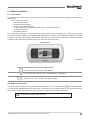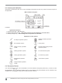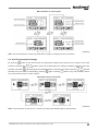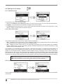
1
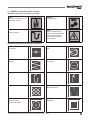
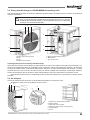
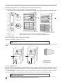
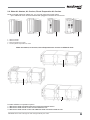
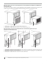
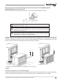
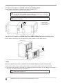
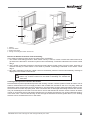
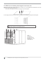
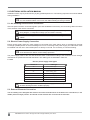
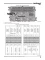
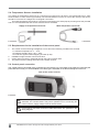
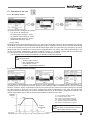
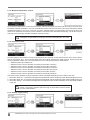
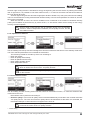
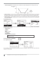
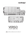
VERSO
S / R / P / RHp / PCF
EN
Installation and Maintenance Service Manual 2
Content
1. VERSO AIR HANDLING UNITS............................................................................................... 4
1.1. VERSO Air Handling Units marking................................................................................... 5
1.2. VERSO-S – Air Supply Units............................................................................................. 6
1.3. VERSO-P/PCF – Air Handling Units Equipped with Plate Heat Exchanger...................... 6
1.4. VERSO-R/RHP – Air Handling Units Equipped with Rotary Heat Exchanger................... 7
1.5. Brief Description of the Unit............................................................................................... 7
1.6. VERSO Air Handling Units Composing Options................................................................ 8
2. VERSO AIR HANDLING UNITS CONSTRUCTION................................................................. 9
2.1. Fans................................................................................................................................... 9
2.2. Plate Heat Exchanger in VERSO-P/PCF Air Handling Units............................................. 9
2.3. Rotary Heat Exchanger in VERSO-R/RHP Air Handling Units.......................................... 11
2.4. Air Dampers....................................................................................................................... 11
2.5. Air Filters and Filter Change Procedure............................................................................ 12
2.6. Water Air Heaters, Air Coolers, Direct Evaporation Air Coolers......................................... 13
2.7. Electric Air Heaters in VERSO-S Series Air Handling Units.............................................. 16
2.8. Electric Air Heaters in VERSO-P/PCF and VERSO-R/RHP Series Air Handling Units..... 16
2.9. VERSO Series Air Handling Units Designed for the Outdoor Use.................................... 18
3. VERSO Air Handling Units Transportation.....................................................................19
4. VERSO AIR HANDLING UNITS INSTALLATION..................................................................... 20
4.1. VERSO Air Handling Units Maintenance Space................................................................ 20
4.2. Setting and Installing VERSO Air Handling Units.............................................................. 21
4.3. Connection to the air duct.................................................................................................. 22
4.4. VERSO Air Handling Units Sloping Drain Tray.................................................................. 22
4.5. Check-up before turning on VERSO Air Handling Unit...................................................... 23
5. ELECTRICAL INSTALLATION MANUAL................................................................................ 24
5.1. Air Handling Units Sections Connection................................................................................. 24
5.2. Electric Power Supply Connection......................................................................................... 24
5.3. External Elements Connection.......................................................................................... 24
5.4. Temperature Sensors Installation...................................................................................... 26
5.5. Requirements for the installation of the control panel....................................................... 26
5.6. Control panel connection................................................................................................... 26
6. OPERATION MANUAL............................................................................................................. 27
6.1. Unit control........................................................................................................................ 27
6.2. Start-up of the unit............................................................................................................. 27
6.3. Control panel indication..................................................................................................... 27
6.4. Parameters Review........................................................................................................... 28
6.5. Unit Programmable Settings.............................................................................................. 29
6.6. Settings of unit modes....................................................................................................... 30
6.6.1. Operation modes..................................................................................................... 30
6.6.2. Flow control modes.................................................................................................. 30
6.6.3. Temperature control modes..................................................................................... 30
6.7. Functions of the unit.......................................................................................................... 31
6.7.1. Air quality control..................................................................................................... 31
6.7.2. Outdoor compensated ventilation............................................................................ 31
6.7.3. Minimum temperature control.................................................................................. 32
6.7.4. Override function..................................................................................................... 32
6.7.5. Summer night cooling.............................................................................................. 32
6.7.6. Operation on demand.............................................................................................. 33
6.7.7. Recirculation control................................................................................................ 33
6.7.8. Humidity control....................................................................................................... 34
2
UAB AMALVA we reserve the right to make changes without prior notice.
6.8. Unit operation scheduling..................................................................................................
6.8.1. Operation program...................................................................................................
6.8.2. Holidays...................................................................................................................
6.8.3. Recirculation schedule.............................................................................................
6.9. Alarms and status..............................................................................................................
6.9.1. Actual alarms...........................................................................................................
6.9.2. Alarm history............................................................................................................
6.9.3. Operation counters..................................................................................................
6.9.4. Efficiency status.......................................................................................................
6.9.5. Filter status..............................................................................................................
6.9.6. VAV status...............................................................................................................
6.10. Settings............................................................................................................................
6.11. Control of air handling units through a web browser.......................................................
6.12. Troubleshooting...............................................................................................................
34
34
35
35
35
35
35
35
36
36
36
36
37
37
This symbol indicates that this product is not to be disposed of with your household waste, according to the WEEE
Directive (2002/96/EC) and your national law. This product should be handed over to a designated collection point,
or to an authorised collection site for recycling waste electrical and electronic equipment (EEE). Improper
handling of this type of waste could have a possible negative impact on the environment and human health
due to potentially hazardous substances that are generally associated with EEE. At the same time, your
cooperation in the correct disposal of this product will contribute to the effective usage of natural resources.
For more information about where you can drop off your waste equipment for recycling, please contact your
local city office, waste authority, approved WEEE scheme or your household waste disposal service.
UAB AMALVA we reserve the right to make changes without prior notice.
3
1. VERSO Air Handling Units
UAB Amalva thanks you for choosing VERSO air hadling unit. Because a lot of attention is given towards unit
quality we will be thankful for your help expressing your comments and responses, or suggestions regarding
technical and running qualities of the unit.
To avoid misunderstandings, before installing the unit, carefully read this instruction. Keep the instruction,
warranty and technical information data – you may need them during exploitation.
Inspect the air handling unit carefully to make sure it was not damaged during
transportation.
More detailed information about the parameters of the VERSO air handling
units can be found in the AHU’s printout (technical specifications).
Do not switch on an ungrounded air handling unit.
Before switching on the unit, all doors must be closed and locked;
the safety covers should be bolted.
Before switching on the unit, its compartments have to be fixed fast among
them.
There is pressure inside the air handling units;
this is why it is forbidden to open any doors before switching off the unit.
Before performing any inspection work inside the unit, be sure the unit‘s
electric power supply is disconnected and there are no rotating parts.
Before opening the doors, switch off the unit and it‘s main switch and wait for 1-2
minutes till the fans will stop rotating.
Before switching on the air handling unit, activate all the safety functions.
The air handling unit can be switched on or off only by the means specified
in the control system.
Be careful when doing water air heater assemblage works - heat exchanger
can get as hot as 1300C!
Warning:
If the air handling unit does not have the manufacturer’s control system,
then the company that installed automation is responsible for the unit’s
functioning and safety reliability.
Risk areas with rotating parts.
Moving parts are the fan impeller, drive pulleys of the rotary heat exchanger,
if fitted, and by-pass/shut-off damper of the plate heat exchanger, if fitted.
The lockable inspection doors serve as protection from contact with the fans
and the heat exchanger. If the fan outlets aren’t connected to any duct, they
must be fitted with a protective screen (wire mesh).
4
UAB AMALVA we reserve the right to make changes without prior notice.
1.1. VERSO Air Handling Units marking
VERSO Air Handling Units marking: warning
Note!
Important information in the
instruction manual.
Place for siphon.
Caution!
Rotating parts!
Note!
Before performing any
inspection work inside the
unit, be sure the unit‘s
electric power supply is
disconnected.
VERSO Air Handling Units marking: informative
Air damper
Fan
Air filter
Air cooler
Rotary heat exchanger
Air humidifying section
Plate heat exchanger
Water air heater
Electrical air heater
Noise attenuator
Inspection
UAB AMALVA we reserve the right to make changes without prior notice.
5
1.2. VERSO-S – Air Supply Units
2
1
8
8
12
3
6
8
9
10
11
5
4
7
1. Air damper (closing)
2. Supply air filters
3. Fan with electric motor
4. Air heater (water or electric)
5. Air cooler (water or direct evaporation)
6. Frequency inverter
7. Base frame
8. Sections connection
9. Sealing gasket
10. Connection bolt
11. Extension module
12. Main module
1.3. VERSO-P/PCF – Air Handling Units Equipped with Plate Heat Exchanger
11
12
13
13
14
14
1
1
6
2
11
5 15
12
6 9
9
10
11
16 15
1. Air dampers (closing)
2. Supply air filters
3. Exhaust air filters
4. Supply air fan with electric motor
5. Exhaust air fan with electirc motor
6. Plate heat exchanger
7. Air heater (water or electric)
8. Air cooler (water or direct evaporation)
9. Main module
10. Base frame
11. Sections connection
12. Sections connection
13. Sealing gasket
14. Connection bolt
15. Frequency inverter
16. Extension module
3
4
7
8
UAB AMALVA we reserve the right to make changes without prior notice.
1.4. VERSO-R/RHP – Air Handling Units Equipped with Rotary Heat Exchanger
11
13
12
13
14
14
11 6 9 11
1. Air dampers (closing)
2. Supply air filters
3. Exhaust air filters
4. Supply air fan with electric motor
5. Exhaust air fan with electirc motor
6. Rotary heat exchanger
7. Air heater (water or electric)
8. Air cooler (water or direct evaporation)
9. Main module
10. Base frame
11. Sections connection
12. Sections connection
13. Sealing gasket
14. Connection bolt
15. Frequency inverter
16. Extension module
3
1
5
2
15
10
16
12 15
4
7
8
1.5. Brief Description of the Unit
• Casings of air handling units are made of galvanized steel sheets, which are powder painted. Mineral wool is
used for thermal insulation and sound attenuation. Unit cover panels are 45 mm thick.
• The air handling units are intended for ventilation of medium-sized and big-sized spaces (eg. shops, offices,
etc.), having operating ambient temperature and relative humidity. As standard, the unit is designed for indoor
and outdoor (with additional parts) placement. The operating temperature range for the unit is -300C ... 400C,
outdoor air temperature.
• The air handling unit is not to be used to transport solid particles, even not in areas where there is a risk of
explosive gases.
• VERSO-R is equipped with a rotary heat exchanger, VERSO-RHP air handling units with a rotary heat exchanger
and a heat pump system, VERSO-P/PCF - with plate heat exchanger, air filters, an electric or water heater, fans
and automation control system, to ensure safe and efficient operation of the unit.
• Before you open the door, the unit must be switched off and the fans must have been given time to stop (up
to 3 minutes).
• The unit contains heating elements that must not be touched when they are hot.
• To maintain a good indoor climate, comply with regulations and, to avoid condensation damage, the unit must
never be stopped apart from during service/maintenance or in connection with an accident.
• If the unit is placed in spaces with high humidity, condensation might occur on the surface of the unit when
outdoor temperatures are very low.
• Under conditions, when the outdoor air temperature is low and humidity is high, risk of heat exchanger frosting may
appear. For this reason anti-frost protection function is foreseen in the controller of the Komfovent air handling units.
Depending on the type of the recovery, different methods of anti-frost protection are available: cold air by-passing,
or / and supply air fan speed reducing. For extremely low outdoor air temperature the duct mounted preheater is
recommended. Counter cross flow heat exchanger is the mostly sensitive for low outside air temperatures, as the
risk of frosting appears in the temperature range from 0 to -50C and below. Standard aluminium cross-flow plate
heat exchanger has better features, as the risk of freezing appears only at -100C. The lowest risk and the highest
resistance to cold outside air is a competitive feature of the rotary heat exchanger, as it is not freezing even at the
temperatures of -300C if the humidity level of the air is appropriate.
UAB AMALVA we reserve the right to make changes without prior notice.
7
1.6. VERSO Air Handling Units Composing Options
VERSO-S
VERSO-P/PCF
VERSO-R/RHP
outdoor intake
supply air
extract indoor
exhaust air
IS-1
Air handling unit inspection doors on the right; supplied airflow into room is on the bottom of the unit.
IS-2
Air handling unit inspection doors on the left; supplied airflow into room is on the bottom of the unit.
IS-3
Air handling unit inspection doors on the right; supplied airflow into room is on the top of the unit.
IS-4
Air handling unit inspection doors on the left; supplied airflow into room is on the top of the unit.
8
UAB AMALVA we reserve the right to make changes without prior notice.
2. VERSO Air Handling Units Construction
2.1. Fans
VERSO air handling units are equipped with radial fans with direct drive.
Motors of the fans with backward curved blades must be controlled by
frequency converters. Frequency set by the frequency inverter cannot
exceed frequency data specified in the print out.
Note: fan type is specified in the print out.
Measuring device for determining air volume
The differential pressure compares the static pressure in front of the inlet ring with
the static pressure in the inlet ring of the narrowest point.
The differential pressure between the static pressures is related to the air volume
via the energy conservation rate as follows: ∇ = k ⋅ ∆p w where k takes into
account the specific ring characteristics.
Example: If differential pressure of 700 Pa is measured for size 630, the air flow
rate can be calculated: ∇ = k ⋅ ∆p w = 381 ⋅ 700 = 10080 (m3/h).
ØDSa
¨32Ø32
–
∆p w
ØLA
Fan
Coefficient - k
Fan
RH22C
47
RH45C
Coefficient - k
197
RH25C
60
RH50C
252
RH28C
75
RH56C
308
RH31C
95
RH63C
381
RH35C
121
RH71C
490
RH40C
154
RH80C
620
+
Cleaning and Inspection of Fans and Fan Space
Polluted fans decrease efficiency.
Before performing any inspection work, check whether the unit is switched
off from the electric power supply.
Inspect and clean the fan impellers to remove possible dirt deposits. Check the impeller to make sure that it is not
out of balance. Clean or brush off the fan motor. It can also be cleaned by carefully wiping it with a damp cloth that
has been dipped in a solution of water and dishwashing detergent. Clean the fan space, if needed.
2.2. Plate Heat Exchanger in VERSO-P/PCF Air Handling Units
When operating the air handling unit equipped with the plate heat exchanger, unit control automation should have
function of protection from frost.
Condensate can accumulate in a plate heat exchanger; therefore it is essential to install siphons on the condensate drainpipes. Depending on the unit construction, plate heat exchanger section may have 1 or 2 siphones.
It is important to maintain cleanliness of the plate heat exchanger: to change
filters installed in the air handling unit on time, if the heat exchanger gets
dirty, to perform heat exchanger periodical cleaning. The temperature effectiveness of a dirty heat exchanger can diminish considerably.
UAB AMALVA we reserve the right to make changes without prior notice.
9
5
2
6
1. Plate heat exchanger
2. Support frame
3. Frame
4. Bottom shields
5. Place of sections connection
6. Bypass damper with actuator
7. Drop eliminator (if needed)
8. Condensate bath with drainage
3
8
4
1
7
Plate heat exchanger can be easily removed for inspection.
Removing plate heat exchanger from VERSO-P/PCF air handling units.
Demounting of the section.
4
9
5
6
2
3
1. Screws are unscrew; bottom shields are removed
2. Plastic axle-pin
3. Screw
4. Frame bolts are removed; the frame is removed
5. Frame
6. Frame bolts
7. Plate heat exchanger is removed
8. Condensate diversion mechanism is removed
9. Bolts connecting the sections are removed
1
8
4
7
Cleaning and Inspection of Plate Heat Exchanger
Always clean against the regular direction of airflow.
Inspection and dedusting of the plate heat exchanger is performed once per year (it is removed from the unit
and blown with an air blast or washed with tepid water).
Inspect the condensate drain to make sure that it isn’t clogged.
10
UAB AMALVA we reserve the right to make changes without prior notice.
2.3. Rotary Heat Exchanger in VERSO-R/RHP Air Handling Units
The heat exchanger actuator mechanism is oiled with synthetic solution; therefore there is no need to oil mechanism
during its exploitation.
It is important to make sure that the rotary heat exchanger mechanism is
clean: to change the filters installed in the air handling unit on time, to perform
periodical heat exchanger cleaning. The temperature efficiency of a dirty heat
exchanger can diminish considerably.
1
2
3
6
6
7
5
5
4
4
1. Rotary heat exchanger frame
2. Rotor
3. Shaft
4. Actuator with a reducer
5. Rotary heat exchanger sensor
6. Main module
7. Heat pump system
Cleaning and Inspection of Rotary Heat Exchanger
Inspection of the rotary heat exchanger is performed once per year. Free rotation of the rotary heat exchanger, continuity of the rotating belt, absence of damages of the rotor drums and the seal gasket are checked. It is necessary
to check the stretch of belt. Free belt will slide and the efficiency of rotary heat exchanger will fall down. To reach
maximal efficiency, rotor must turn at least 8 times per minute. Polluted heat exchanger will decrease efficiency.
Clean heat exchanger with an air blast or wash with tepid water. Check out water falling on the electric motor.
If the fabric drive belt is worn or substantially fouled, it should be replaced. Do not lubricate it! Contact service
personal.
2.4. Air Dampers
Closing air dampers with aluminium or galvanized steel blades are used in the units.
Air damper is fixed to the air handling unit with screws.
1 2
5
5
6
4
3
1. Aluminum or galvanized steel blades
2. Rubber sealing
3. Plate shaft for the actuator
4. Shaft for bypass damper closing/opening
5. Fastening bend
6. Screw
UAB AMALVA we reserve the right to make changes without prior notice.
11
Installing Electrical Drives on the Air Dampers. Electrical Dampers Safety.
The electrical actuators control air dampers of the air handling unit.
If air handling unit is installed outside, then all the drives outside have to be protected from moisture and dust.
1
2
1. Electric drive fixed to the air handling unit installed in a building
2. Electric drive fixed, under the cap, to the air handling unit installed outdoors
2.5. Air Filters and Filter Change Procedure
Synthetic or fiberglass bag filters are used.
When operating the air handling unit, the unclean filters should be changed
on time.
Pressure level drop at which it is recommended to change filters, and the measurements are in the technical data
pages.
1
1
2
2
3
1. Upper filter holder
2. Lower filter holder
3. Changeable filter
Air filter clogging check
The filters should be changed when the filter alarm has been activated. We recommend to change filters at least
twice per year: before and after heating season, or more. Clogged filters unbalance ventilation system, air handling
unit uses more power.
If air handling unit is working in small speed, the filters must be checked on unit maximum speed. Filters are
one time used. We do not recommend cleaning them. Stop the air handling unit before changing filters.
Before changing air filters, check whether the unit is switched off from the
electric power supply.
12
UAB AMALVA we reserve the right to make changes without prior notice.
2.6. Water Air Heaters, Air Coolers, Direct Evaporation Air Coolers
Mostly used with aluminum plates (2.5; 3 or 4 mm fin pitch) and copper pipes.
Upon additional order can be assembled with plugged connection for frost sensor.
1
1.
2.
3.
4.
2
3
4
Water air heater
Water air cooler
Direct evaporation air cooler
Two-step direct evaporation air cooler
Water Air Heaters, Air Coolers, Direct Evaporation Air Coolers in VERSO-S Units
2
1
3
Possible VERSO-S composition options:
1. With the air heater mounted inside the unit and recirculation section.
2. With the air heater and air cooler mounted inside the unit.
3. With the air heater and air cooler and additional heater mounted outside the unit.
UAB AMALVA we reserve the right to make changes without prior notice.
13
Water Air Heaters, Air Coolers, Direct Evaporation Air Coolers Mounted at the Bottom of VERSO-P/PCF,
VERSO-R/RHP Units
The section of air heater, air cooler, or direct evaporation air cooler insulated in mineral wool is mounted on the
outside of the unit. Therefore air handling unit takes less space and it is more convenient to install.
1
1. VERSO-R/RHP or VERSO-P/PCF with air heater installed outside the unit
2. VERSO-R/RHP or VERSO-P/PCF with air heater or air cooler installed outside the unit
2
Water Air Heaters, Air Coolers, Direct Evaporation Air Coolers Mounting Types at the Top of
VERSO-P/PCF, VERSO-R/RHP Units
1
2
3
1. VERSO-R/RHP or VERSO-P/PCF with air heater and air cooler positioned on the welded frame outside the unit (base frame with
legs for heat recovery section - only as additional set)
2. VERSO-R/RHP or VERSO-P/PCF with air heater and air cooler suspended outside the unit (hanging bar - only as additional set)
3. VERSO-R/RHP or VERSO-P/PCF with a suspended air heater outside the unit
14
UAB AMALVA we reserve the right to make changes without prior notice.
Water Air Heater, Air Cooler, Direct Evaporation Air Cooler Connection to VERSO-P/PCF and
VERSO-R/RHP Series Air Handling Units
When connecting heat exchanger to the system, it is necessary to use two pipe wrenches:
Be careful when exploitating hot water air heaters as the heating agent
temperature may reach 1300C!
When operating air handling unit in the temperatures lower than 00C, it is
necessary to use glycol additionally or assure the reversible heating agent
temperature more than 250C.
It is important to maintain air heaters and coolers cleanliness; that is to
change filters installed in the air handling unit on time. If the air heater or
cooler gets dirty, to perform periodical cleaning.
Glycol is used in the air handling units with coil heat exchanger. Never pour glycol down a drain; collect it in a
receptacle and leave it at a recycling centre or the like. Glycol is highly dangerous to consume and can cause fatal
poisoning or damage the kidneys. Contact a doctor! Avoid breathing glycol vapour in confined spaces. If you get
glycol in your eyes, fush them thoroughly with water (for about 5 minutes).
1
1
2
3
3
1. Electric/Water heater, Air cooler or direct evaporation air cooler mounting pin
2. Frame
3. Gasket
Cleaning and Inspection of Coil Heat Exchanger
Always clean against the regular direction of airflow. Make sure that the coils are purged of air. If a droplet eliminator
is fitted, remove it and fush it clean with water. Also check that the condensate drain is not clogged.
UAB AMALVA we reserve the right to make changes without prior notice.
15
2.7. Electric Air Heaters in VERSO-S Series Air Handling Units
Electric heater is mounted as a middle section of an air handling unit.
Three interconnected unit parts are bolted together.
When heating capacity exceeds 45 kW, additional electric heater section may
be used (also up to 45 kW). In such a case additional heater is connected to
the supply air vent (after the ventilation section).
Each electric heater section has separate main-switch to which electric power
supply is connected.
1
3
1. Electric heater
2. Heater main-switch
3. Unit main-switch
2
2.8. Electric Air Heaters in VERSO-P/PCF and VERSO-R/RHP Series Air Handling Units
Electric heater is mounted to the unit supply air vent and screwed to a side panel with pins.
1
2
3
1. Pin, by which electric heater is mounted to the unit supply air vent
2. Frame
3. Gasket
Electric Air Heater Connection to VERSO-P/PCF and VERSO-R/RHP Series Air Handling Units
a)After opening doors of the air handling unit, linkage (4) connecting the heater and the unit is connected.
b)Unit electric power supply is connected to the heater introductory main-switch (3). Unit electric power supply is
connected. The cable is put through the sealant (1).
Before doing connections, make sure that the introductory main-switch is off or
electric power supply is off.
16
UAB AMALVA we reserve the right to make changes without prior notice.
2
1
4
3
3
1. Sealant
2. Unit main-switch
3. Heater main-switch
4. Linkage connecting the heater and the unit
Electric Air Heaters Protection from Overheating
Three safety measures protect electric air heaters from overheating.
1. 700C heater overheating protection. When airflow velocity is too low, it does not allow the heater elements to
get hotter more than 2000C. Protection system works automatically, overheat is indicated on the remote control
device.
2. 1000C heater overheating protection. After disconnecting electric power supply from the heater, protection is
restored manually: the reset switch on the heater is pressed; overheating is indicated on the remote control
device.
3. 600C triac overheating protection. Heater control is terminated, protection resumed automatically, message is
displayed on the remote control device.
There is a possibility to resume overheat danger safety by pressing RESET
button only if before reasons for the heater overheating are clarified and
eliminated.
Cleaning and Inspection of Electric Air Heaters
Recommended to perform periodical inspection and cleaning of heater. Check the plates of water air heater. The air
heater is cleaned with hoover from supply air side or with air blast from exhaust air side. If it is very dirty, wash with
tepid water, which will not make corrosion of aluminium. Check if position of return water temperature sensor is right.
Check if electric air heater is properly fixed, wires connections are not damaged and heating elements are not bent.
They can be damaged or bent due to uneven heat or uneven and turbulent air direction. Check if electric air heater
is clear of unnecessary things and heating elements are not clogged, because this can cause unpleasant smell or
in the worst case – dust can start burning. Air flow through the air heater should be greater than 1,5 m/s. Heating
elements can be cleaned with hoover or wet textile.
UAB AMALVA we reserve the right to make changes without prior notice.
17
2.9. VERSO Series Air Handling Units Designed for the Outdoor Use
VERSO air handling units, which are designed for outdoor use, can be additionally assembled with roofs with
water drain tray to opposite viewing side.
Every section has separate roof which must only be connected together.
2
3
On the supply and exhaust air vents, there is a possibility to mount additional casings and external grills.
Joints need to be additionally sealed, if units are intended to be used
outside. Sealant is not included in unit set.
6
5
4
7
1
1. Roof
2. Roof plate
3. Roof plate fixer
4. Air intake vent casing
5. Exhaust air vent casing
6. External grills
7. Valve actuator cap
18
UAB AMALVA we reserve the right to make changes without prior notice.
3. VERSO Air Handling Units Transportation
VERSO Air Handling Units Transportation by Crane, Lift Truck and Carts
The unit is transported separately.
While transported, each section is fixed to a wooden pallet and wrapped.
Dampers and flanges are supplied not fixed to the unit. They are on the top of each unit section.
Sealing, connecting and fixing bolts are inside in each section. Base frame is separate from the unit during
the transportation.
When unit is loaded or unloaded by crane, cargo rope is fastened in its designated places.
Lift truck or cart can transport air handling unit as it is shown in the pictures.
A
B
D
C
E
A. Separate unit part is lifted by crane on a wooded pallet
B. Unit is transported by lift truck on a wooded pallet
C. One section of the unit is transported by lift truck on a wooden pallet
D. One section of the unit is transported by cart on a wooden pallet
E. Carts on a wooden pallet transport the unit
UAB AMALVA we reserve the right to make changes without prior notice.
19
4. VERSO Air Handling Units Installation
4.1. VERSO Air Handling Units Maintenance Space
Maintenance space is needed for convenient inspection of the unit; perform maintenance works; when there is a
need to pull it out for inspection, change parts of the unit or even the whole unit.
In order to change some unit components, there might be a need to demount the unit partially or completely.
The minimal unit maintenance space range is enough to change air handling unit filter.
Size of the unit
A
Amin
H
B
10
1000
850
500
500
20
1150
950
500
500
30
1300
950
500
500
40
1500
950
500
500
50
1700
950
500
500
60
1900
950
500
500
70
2100
950
500
500
80
2300
950
500
500
90
2500
950
500
500
VERSO-P/PCF, VERSO-R/RHP air handling unit middle doors open up, only
if the side doors are opened.
H
B
A min
A
A recommended space for the unit maintenance
Amin minimal necessary space for the unit operation
H free space over the installed air handling unit
B recommended space behind the air handling unit
20
UAB AMALVA we reserve the right to make changes without prior notice.
4.2. Setting and Installing VERSO Air Handling Units
Before installing air handling unit it is important to remove transportation elements. If the unit was transported not
on the positioning frame, sections should be placed from wooden panels to positioning frame.
The unit is installed on even and solid base, location that was assigned to it. According to the unit weight,
which is indicated in technical specifications, dimensions and other important parameters special construction
calculations should be done.
If the unit is ordered with adjustable feet, unit can be leveled with its help. Leveling up to 50 mm.
If the surface on which the unit is installed is not even, the air handling unit
can distort, because of that doors may not close correctly, there may be gaps
between jointed sections.
It is advisable to put a gum seal between the air handling unit and the base.
It is forbidden to install the air handling units one on the other.
Wiring connection,- see electrical installation manual.
1
1
2
1. Fastening place for the key to the doors during air handling unit transportation
2. The key
Noise Caused by VERSO Air Handling Units
Air handling unit causes some acoustic noise (more specific data is available in the technical unit specification)
and this has to be taken into consideration when installing air handling unit. Comfort in the facilities depends not
only on the air handling unit, but also on the quality of the ventilation system, installment quality and other factors
(noise reduction means and etc).
Recommended:
• To install air handling unit not closer than 500 mm from a wall (if needed - use additional noise reducing materials,
for example, layers of mineral wool).
• Make sure that vibration from the air ducts does not transmit to the building construction; therefore it is
recommended to use flexible connectors, absorbing air duct holders. Air ducts must be selected so that air flow
would not create additional noise and vibration.
• Air handling unit has to be installed on a fairly massive and solid base, considering mass of the unit and the
construction standards. It is recommended to lay gum sheets between air handling unit and the base.
UAB AMALVA we reserve the right to make changes without prior notice.
21
4.3. Connection to the air duct
VERSO Air Handling Unit is connected to the Air Duct in Two Ways
Air ducts are connected to VERSO units through L-20 connectors.
VERSO units of size 60, 70, 80,90, are connected through L-30.
Air damper connection to the air duct
2
1. Bolt
2. Connector
3. Flange
4. Air duct
5. Single-sided adhesive gasket
1
3
4
5
Flange connection to the air duct
Screwed bolts M8x20 in the corners. Special adhesive gasket ensures tightness.
2
1
1. Bolt
2. C profile for flange connection
3. Single-sided adhesive gasket
3
2
4.4. VERSO Air Handling Units Sloping Drain Tray
The bend of the water trap can be repositioned by turning it to the right or the left. The drain line from the water
trap must be arranged so that it will not damage adjacent unit sections or building elements. If the drain line is run
through cold spaces, it should be insulated to prevent freezing. A heating cable may be required.
Water trap installation for a unit section mounted on the suction side
Since the fans in most air handling units are last in the chain of functions and generate sub-atmospheric pressure
inside the unit,it is very important to correctly install the water trap. Because of that reason condensate can be
hardly eliminated from the air handling unit and the technical premise may get covered with condensate. Height
H1 must be at least equivalent in mm to half of the negative pressure inside the unit in mm water gauge. Height H2
must be at least equivalent in mm to the negative pressure inside the unit in mm water gauge.
Siphon with the spherical valve
Siphon without the valve
Condensate
95
106
DN 40
Ø 32
25-240
Condensate
H1, H2
140-310
22
UAB AMALVA we reserve the right to make changes without prior notice.
H2
H1
Precaution: The drainage siphon should be mounted on the outlet fitting
pipe of every drip tray for complete condensate drainage from the air handling
unit and prevention of penetration of offensive odours from an effluent into
the ventilation system.
In case of the outdoor operation of the air handling unit, the siphon and the
bleeders should be heated with an electric thermal cable (if ambient air
temperature tamb < 00C). The siphon and the bleeders should be heat-insulated
with an insulating material.
Water trap installation for a unit section mounted on the pressure side
Since the fans in most air handling units are not last in the chain of functions and generate over-atmospheric
pressure inside the cooling section. In such case the consisted condensate can be easily removed from AHU and
there will be no strict requirements for siphon‘s installation. A drainage siphon is enough with a minimum rake.
RECOMMENDATION: The drainage siphon must be installed in connection with not less size pipe diameter.
4.5. Check-up before turning on VERSO Air Handling Unit
•
•
•
•
•
•
•
Before turning on air handling unit, clean installment dust and waste.
Check whether cable and wires are connected firmly.
Take off the unit all supporting shields and covers and other things left after installment of the unit.
Before turning on the unit, it is necessary to close all the doors and bolt all protection shields.
Check whether air dampers open and close properly.
Check whether heat exchangers are connected tightly.
The air handling unit can be turned on only according to projected control system order (if the air handling unit
has the manufacturer’s automation, see control system instruction).
• If the air handling does not have manufacturer’s control system, the company installing control system is
responsible for the unit’s functioning and safety reliability.
• Before operating the unit air handling system tune-up works must be performed.
VERSO Air Handling Units Warranty Conditions
Warranty is not valid if the unit was installed or operated improperly, or it was damaged mechanically, also if the
unit constituent parts are changed unauthorized or operation conditions are not suitable (aggressive environment,
humidity, etc.)
It is forbidden to destroy wilfully air handling unit sections frames, fan, motor, or other air handling unit parts
during warranty period. If this requirement is not followed, the unit will not be serviced under the warranty service
conditions.
When operating the unit, periodical air handling unit checks-ups by the user should be recorded in the Technical
Service Register. Qualified specialist authorized by the user should make the entries.
When operating the air-handling unit, most important is to check the components that get dirty the soonest
(for example, filters, heat exchangers, etc.). Periodical check-ups of the air handling unit are done every 4 months.
During the check-up the heat exchanger condition is checked, whether the condensate drainage siphon and other
components of the air handling unit are not dirty. When the filters are dirty, the warning system informs about it,
such system has to be installed when installing the unit.
Check-ups and technical service has to be performed by the qualified specialists.
It is necessary to follow the instructions of heating system, during exploitation period of the unit.
Specific warranty conditions are in unit warranty list.
UAB AMALVA we reserve the right to make changes without prior notice.
23
5. ELECTRICAL INSTALLATION MANUAL
Installation works may be performed only by duly qualified personnel. The following requirements must be fulfilled
during installation.
It is recommended to lay control circuit cables separately from power cables
or to use shielded cables. In this case, the cable shielding must be grounded!
5.1. Air Handling Units Sections Connection
After unit parts have been connected together (see Units Installation Instructions), the connecting cables and wires
of the sections of the unit are connected.
Connector connection is performed strictly according to numeration given in
wiring diagram, or adequate markings (see unit electric scheme).
When disconnecting sections of the unit, do not pull connecting wires and
cables!
5.2. Electric Power Supply Connection
Electric power supply (400V AC; 50Hz voltage) is connected to the main switch, which is envisaged in the heat
exchanger (middle) section of the air handling unit. Prior to connecting to the power supply, the main switch must
be installed near the unit in the intended place or directly on its wall. It is necessary to connect earthing!
Unit must be connected to the stationary installation by solid cable through
circuit breaker with 300mA current leakage protection.
The power supply cable of the unit and electrical heater is selected according to the maximum current strength
indicated in the presented technical data sheet. The cable types are indicated in Table 5.2.
5.2 Table
Electric power supply cable types
Current, A
Cable type
15
5 x 1,5 mm2 (Cu)
21
5 x 2,5 mm2 (Cu)
27
5 x 4,0 mm2 (Cu)
34
5 x 6,0 mm2 (Cu)
50
5 x 10,0 mm2 (Cu)
70
5 x 16,0 mm2 (Cu)
85
5 x 25,0 mm2 (Cu)
Before connecting unit to the electrical power supply, it is necessary to check
whether earthing has been installed properly.
5.3. External Elements Connection
The air handling unit is designed with external connection terminals which are located on the controller box, in the
middle (heat exchanger) section. All external control elements are connected to the terminals.
24
UAB AMALVA we reserve the right to make changes without prior notice.
Controller with connection terminals
1
2
5.3 a Picture
1. Control panel connection
2. „Ethernet“ computer network or internet connection
External control elements connection
5.3 b Picture
UAB AMALVA we reserve the right to make changes without prior notice.
25
5.4. Temperature Sensors Installation
The supply air temperature sensor B1 (5.4 a Picture) is mounted in the air duct in a projected place for it; after
electric heater or cooler section (if provided). The minimal distance from the air vent of the unit up to the sensor
should be not less than a diagonal of rectangular connection.
The water temperature sensor B5 (5.4 b Picture) is mounted on the water pipe by screwing it into the provided
hole. It is recommended that the sensor would be thermo nsulated!
Supply air temperature sensor B1
Water temperature sensor B5
5.4 a Picture 5.4 b Picture
5.5. Requirements for the installation of the control panel
1. The control console should be installed in a room where the following conditions are ensured:
1.1. Ambient temperature: 00C ... 400C;
1.2. Relative humidity range: 20% ...80%;
1.3. Protection against vertical dripping of water (IP X2).
2. Installation height: at least 0.6m from the floor.
3. Control panel connection: designed through the hole in its back side.
4. The panel is fixed by drilling two holes on the fixation surface.
5.6. Control panel connection
The control panel is connected to the controller box (see Picture 5.3). The length of the cable for connecting the
panel with the unit may not exceed 150 m. The cable type is indicated on the electrical diagram of the unit.
View of the control console
5.6 Picture
When closing the console cover, do not bend the springs inside the console;
otherwise, the console buttons may fail to operate! Prior to connecting the
control console, supply voltage must be disconnected!
Control panel connection and other cable thicknesses are specified in the
wiring diagram!
26
UAB AMALVA we reserve the right to make changes without prior notice.
6. OPERATION MANUAL
6.1. Unit control
Air handling units control system ensures control of the physical processes that are taking place inside the air
handling unit.
Control system consists of:
• main controller module;
• several extension modules;
• circuit breakers and main switch;
• control console, which may be installed in a place convenient for the user;
• air dampers actuators;
• temperature sensors.
The control panel (Picture 6.1) is designed for the remote control of the air handling unit, setting of the controller
parameters and their indication. Control panel LCD display allows monitoring various parameters and text messages.
The light diode of the panel indicates the operation mode and fault of the unit. Air temperature, ventilation intensity,
operation modes and other parameters are set by the touch sensitive buttons.
Control panel
6.1 Picture
Touch sensitive buttons located on the panel mean:
on / off and return to previous menu window;
entry to parameters change menu / set parameters confirmation;
navigation in the menu / parameters value change.
6.2. Start-up of the unit
The unit is started up (shut down) by pressing and holding down for 4 seconds the on/off
button After switching
on, unit will start operating after short delay about 45 seconds), until air dampers open up, and fans start running.
The operation of the unit is indicated on the display of the panel and by a light diode signal.
Do not switch on the unit without connected earthing! Make sure, whether all
unit sections are tightly interconnected.
UAB AMALVA we reserve the right to make changes without prior notice.
27
6.3. Control panel indication
Information is presented to the user on the LCD display of the panel as well as by means of luminous signals of
the light diode.
Main window of the panel
6.3 Picture
Light Diode Indication:
1. Constant green light – the unit is on;
2. Flashing red and green light – fault alarm; however, the unit operation is not shut down;
3. Flashing red light only – fault message; the unit operation is shut down.
Explanation of the symbols
Air damper operation symbol
Holliday schedule operation
symbol
Fan operation symbol
Fault symbol
Energy recovery operation
symbol
Summer night cooling function
operation symbol
Heating operation symbol
Air volume down symbol
Cooling operation symbol
Air volume up symbol
Recirculation operation
symbol
„OVR function symbol
Preset schedule operation
symbol
6.4. Parameters Review
The main parameters of the unit are indicated in four main windows of the panel (Picture 6.4). In order to review
,
buttons should be used. In this manner, the panel windows can be switched to the
the parameters,
temperatures, air volume or quality (air humidity) indication window.
28
UAB AMALVA we reserve the right to make changes without prior notice.
Main windows of control panel
6.4 Picture
Note: The fourth window is shown only when the air quality or humidity function is activated.
6.5. Unit Programmable Settings
By touching
button in the main window, the parameters setting menu (Picture 6.5) is entered. The menu
window is selected with
selected, the button
,
buttons. When the required menu for setting the desired parameter has been
is pressed again and the desired item is selected or the value is set with
selection is set, the value is confirmed by pressing
you to the previous menu or main window.
again. Pressing
,
. After the
button in any menu window returns
Parameters menu of the panel
6.5 Picture
Note: If touch buttons are inactive for 1 minute, the main panel window appears automatically.
UAB AMALVA we reserve the right to make changes without prior notice.
29
6.6. Settings of unit modes
6.6.1. Operation modes
Six operation modes of the unit are possible:
1. There is two Comfort and two Economy modes, for each of them the user can set air flow and temperature;
2. Program – in this mode the unit operates according to the preset schedule;
3.The Special mode allows the user not only to set air flow and temperature, but also to select blocking or using
heating, cooling, and recirculation and other functions.
6.6.2. Flow control modes
The following supply and extract air flow control modes are designed:
• CAV – constant air volume control mode. The unit will supply and extract a constant air flow which is preset by the
user, irrespective of any changes occurring in the ventilation system;
• VAV – variable air volume control mode. The unit will supply and extract an air flow with regard to the ventilation
needs in different rooms. In case of frequently changing ventilation demands this air volumes maintenance mode
signally reduces unit exploitation costs.
It is possible to use a simplified VAV control function, “single-flow VAV control”. It means that the performance of
this function requires only a single air flow pressure sensor, which is installed in a variable air duct system (e.g. in
supply air). This variable system is called the master ventilation system, according to which control is performed,
while the other air flow (in this case, discharged air) operates as the slave ventilation system and always follows
the master one. If the supply air requirement in the ventilation system which is assigned as the master system
decreases, the intensity of discharged air in the slave system is reduced correspondingly by the same percentage.
If the variable air volume control function is designed in the ventilation unit,
the initial calibration of the control mode must be performed (see Paragraph
6.9.6); otherwise, the unit will not operate if the VAV mode is selected.
6.6.3. Temperature control modes
The air handling unit provides for several temperature control modes: supply air, extract air or room air temperature
maintenance.
30
UAB AMALVA we reserve the right to make changes without prior notice.
6.7. Functions of the unit
6.7.1. Air quality control
Air quality control is designed according to:
•
•
•
•
•
CO2 sensor* [0...2000 ppm];
Air quality sensor VOCq [0...100%];
Air pollution sensor VOCp [0...100%];
Relative humidity sensor [0...100%];
Temperature sensor [0...500C].
* - factory setting.
Depending on the type of the selected sensor, the value of the air quality function to be maintained is set, and the
air handling unit intensity will be adjusted according to that value. Ventilation intensity will be increased automatically
in the case of deviation from the set value and decreased again when it is approached. For example, if the unit is
designed with the CO2 maintenance function and is equipped with a CO2 sensor, after setting value 800 ppm, this
set CO2 level will be maintained by adjusting ventilation intensity, i.e. ventilation intensity will be increased if the
CO2 level grows and will be decreased when it returns to the previous condition.
Two air quality value settings for separate unit operation modes are possible.
The function of air quality operates only if no other below function is active at
the same time:
• Summer night cooling
• Min. temperature control
• Recirculation control
• Outdoor compensated ventilation
6.7.2. Outdoor compensated ventilation
The ventilation compensation function adjusts the air volume depending on the existing outdoor temperature. It is
possible to enter four temperature points, with two of them defining winter conditions and the other two defining
summer conditions. When compensation start and end points for both winter and summer seasons are entered
(it is also possible to enter only one of them, example only winter compensation; in this case, the start and the
end points should be the same), the current ventilation intensity will be decreased in proportion according to the
outdoor temperature until it reaches the minimum possible ventilation level of 20%.
Ventilation
intensity,
%
F1 - user-selected air flow (actual)
F2 - minimum air flow 20%
W1 - winter compensation start point
W2 - žiemos kompansavimo pabaiga
S1 - summer compensation start point
S2 - summer compensation end point
outdoor
temperature,
C
UAB AMALVA we reserve the right to make changes without prior notice.
The ventilation compensation function does not operate when summer
night cooling function is active.
31
6.7.3. Minimum temperature control
The minimum temperature control function forcibly reduces the supply and extract air flow set by the user when
the heater capacity available in the unit is insufficient and/or heat recovery does not ensure minimally possible
temperature supply to the room. The user can set a separate supply air temperature value so that when that
value is not achieved, the intensity of the ventilation unit starts to be reduced automatically. The air flow may be
reduced to the minimally possible ventilation intensity of 20%.
In ventilation intensity control, this function has top priority over the functions
“Ventilation compensation according to the external temperature” and “VAV”.
6.7.4. Override function
Override (OVR) control of the unit can be performed by the external contact (see Picture 5.3b) or device (timer,
switch, thermostat, etc.). The received signal from the outside activates the OVR function, which ignores the
current operation modes of the unit and performs one of the selected actions listed below:
• Switches off the air handling unit;
• Switches over the unit to operation according to the mode “Comfort1”;
• Switches over the unit to operation according to the mode “Comfort2”;
• Switches over the unit to operation according to the mode “Economy1”;
• Switches over the unit to operation according to the mode “Economy2”;
• Switches over the unit to operation according to the mode “Special”;
• Switches over the unit to operation according to the weekly schedule.
The OVR function provides for three operation modes selectable depending on the needs of the user:
1. The mode “When on” – the function will respond to the external control contact only when the air handling unit is on.
2. The mode “When off” – the function will respond to the external control contact only when the air handling unit is off.
3. The mode “Always” – the function will respond to the external control contact irrespective of the operating condition
of the unit.
The OVR function has the top priority and, therefore, ignores all previous
modes. The function remains active as long as the external control contact
is in the closed position.
6.7.5. Summer night cooling
32
UAB AMALVA we reserve the right to make changes without prior notice.
Summer night cooling function is intended for energy saving during the summer season: by utilizing the outside
chill of night hours, it is possible to cool down heated rooms, i.e. to remove excessive heat that accumulated in
the room during day hours.
Summer night cooling function can start at night (from 00:00h to 06:00h a.m.) at any time, when the air handling
unit is on and the fans are running at least at their lowest intensity. User can set temperature for extract air, at which
this function is activated.
When this function is active, the current ventilation level is switched to the maximum ventilation intensity
(100%) and ventilation is performed only by means of fans, i.e. at that time neither the air cooling nor the energy
recovery functions operate.
Summer night cooling function has an operating priority over the following
functions: outdoor compensated ventilation, the air quality function, and the
recirculation function.
6.7.6. Operation on demand
The air handling unit start-up function is designed to start the unit which at that time is in the standby mode when
one of the selected parameters has exceeded the critical limit.
•
•
•
•
•
The function provided for the start-up of the unit according to:
Room CO2 sensor;
Room air quality sensor VOCq;
Room air pollution sensor VOCp;
Room relative humidity sensor;
Room temperature sensor.
Operation on demand (start-up / shut-down) is performed by the same sensor
which is used in the control of the “Air quality function”.
A room sensor with the analogue output (0...10V DC) should be designed
for this function.
6.7.7 Recirculation control
The air handling unit with a mixing section has the extract air recirculation function, i.e. when the extract air flow
is returned to the room.
Recirculation can be performed according to:
• Room air quality*. In this case air quality sensor should be additionally connected to the controller terminals
“Air quality sensor”. The user can set the air quality value to be maintained so that when it is exceeded, the
recirculation damper is closed and the unit supplies more fresh air.
Recirculation according to air quality is performed by the same sensor which
is used in the control of the “Air quality function”.
* - default setting
UAB AMALVA we reserve the right to make changes without prior notice.
33
• External temperature. Recirculation will be controlled to the external temperature curve set by the user, e.g.:
Recirculated air,
%
Outdoor
temperature,
С
• Weekly schedule. The user can set an automatic program for the whole week where the following can be assigned:
the moment and percentage of required recirculation. The recirculation schedule is set with the scheduling menu.
• External contact. If a device (switch, relay, timer, etc.) is connected to the external control terminals (see Picture
5.3 b), recirculation will be activated when the contacts are short-circuited and will operate at the recirculated/fresh
air ratio set by the user.
6.7.8 Humidity control
Air handling unit can be ordered with air humidity control function. In this case one of the humidity control possibilities
should be noted in advance.
Control location:
• supply air;
• extract air;
• room;
Method of control:
• humidification;
• dehumidification;
• humidification & dehumidification.
Air dehumidification is possible only in case if air handling unit is provided
with air cooler.
6.8. Unit operation scheduling
6.8.1. Operation program
For air handling unit up to 20 operation programs can be set. An operation mode and a day of the week can be
assigned to each program.
34
UAB AMALVA we reserve the right to make changes without prior notice.
6.8.2. Holidays
The holiday schedule specifies the time period during which the air handling unit will operate according to the
specified mode. Up to 10 holiday schedules can be set.
6.8.3. Recirculation schedule
The recirculation level in terms of percentage points and operation time are set. Up to 5 recirculation schedules
can be set.
This menu item is available when recirculation control according to the weekly schedule is activated.
6.9. Alarms and status
6.9.1. Actual alarms
This menu shows messages on existing faults. Messages are deleted when “Delete” is selected.
6.9.2. Alarm history
Former messages are shown here.
6.9.3. Operation counters
This menu shows the operation time or energy consumption of the heater and fans.
UAB AMALVA we reserve the right to make changes without prior notice.
35
6.9.4. Efficiency status
The menu is designed to monitor the efficiency of the heat exchanger and fans.
6.9.5. Filter status
It is possible to monitor the pollution level of filters and to calibrate clean filters.
6.9.6. VAV status
In this menu, it is possible to calibrate the VAV function and to review its mode.
Calibration of the variable air volume control mode:
1. Prior to starting the unit, it is necessary to adjust the air distribution and exhaust devices contained in the
ventilation system and to open all variable air volume valves in the branches and channels so that air would be
supplied to all rooms to be ventilated.
2. To start the air handling unit and, in accordance with the diagram shown above, to start the VAV calibration. The
VAV mode status will change to Calibration. When calibration is completed, the VAV mode status will change to
Supply, Extract or Double depending on the configuration of the pressure sensors.
3. When the calibration process is completed, the air handling unit will continue operation in the previous mode.
6.10. Settings
This menu is designed to set the language, date, time, measurement units,
and addresses and to reset the password and factory parameters.
36
UAB AMALVA we reserve the right to make changes without prior notice.
6.11. Control of air handling units through a web browser
You may not only monitor the operation of VERSO air handling units and the functionality of their individual
components, change settings and activate extra functions by means of control panel but also by your computer.
All you need is to connect the unit to the computer, local area network or the Internet using a network cable.
Standard CAT 5
network cable
How to connect the unit directly to your computer:
1. Plug one end of the network cable into the controller port on the unit (see Picture 5.3 a) and the other end to
the computer.
2.Go to the properties of your network card and enter IP address, e.g. 192.168.0.200, and subnet mask
255.255.0.0.
3. Open the web browser on your computer and disable all proxy servers in the settings.
4. In the address bar of your web browser enter the IP address associated with the air handling unit; the default
IP address is 192.168.0.50. You can change it at any time on the control panel or from web browser (see
connection settings)
Note: It is recommended to download the latest version of your web browser before use.
5.If the connection is successful, a window prompting to enter your user name and password appears:
Note: the user name is “user”. The initial password is also “user”; after logging in, the user can later change
the password to any other of his/her choice (see user interface settings).
In case you forget your new password, you can restore the initial password
“user” at any time through control panel settings.
6.12. Troubleshooting
If the unit fails to operate:
• Make sure that the unit is connected to the power supply network.
• Check whether the main switch (if designed) is turned on.
• Check all fuses of the automatics. If necessary, replace blown-out fuses with new ones having the same electrical
parameters (the sizes of the fuses are indicated on the schematic electrical diagram).
• Check whether there is any failure message on the control panel. If there is indication, it needs to be eliminated first.
In order to eliminate the failure, follow the table.
• If nothing is indicated on the control panel, check whether cable connecting control panel with the unit is not
damaged.
UAB AMALVA we reserve the right to make changes without prior notice.
37
6.12 Table
Failures indicated on the control panel, their possible causes and elimination methods
Message
Possible cause of the fault
Elimination of the fault
Low supply air flow
Too high resistance of the ventilation
system.
Check pressure pipes, air dampers, air filters
and make sure that the ventilation system is
not blocked.
Low extract air flow
Too high resistance of the ventilation
system.
Check pressure pipes, air dampers, air filters
and make sure that the ventilation system is
not blocked.
VAV calibration fail
Pressure sensors are not connected
or broken.
Check connections of the sensor or replace
the sensor.
Change outdoor air filter
The fresh air filter is blocked.
Shut down the unit and replace the filter.
Change extract air filter
The extract air filter is blocked.
Shut down the unit and replace the filter.
Electric heater off
The heater is disconnected due to too
low air volume.
As soon as the heater cools down, protection resets automatically. It is recommended
to increase the ventilation intensity level.
Service mode
The controller input and/or output is
manually set in the service mode.
Set the inputs and/or outputs into automatic
control.
Supply air temperature
sensor failure
The supply air temperature sensor is
not connected or broken.
Check connections of the sensor or replace
the sensor.
Extract air temperature
sensor failure
The discharged air temperature sensor
is not connected or broken.
Check connections of the sensor or replace
the sensor.
Outdoor air temperature
sensor failure
The external air temperature sensor is
not connected or broken.
Check connections of the sensor or replace
the sensor.
Exhaust air temperature
sensor failure
The exhaust air temperature sensor is
not connected or blocked.
Check connections of the sensor or replace
the sensor.
Water temperature sensor
failure
The water temperature sensor is not
connected or broken.
Check connections of the sensor or replace
the sensor.
Return water temperature
low
Return water temperature of the heater
dropped below the permissible limit.
Check the status and operation of the
circulation pump, heating system and mixing
valve actuator.
Internal fire alarm
Fire danger in the ventilation system.
Check the ventilation system. Find the
source of the heat.
External fire alarm
A fire signal has been received from the
fire signalization system of the building.
Delete alarm message and restart the unit
when the fire signal disappears.
External stop
A signal from an external device (switch,
timer, or sensor) has been received.
As soon as the auxiliary device is switched
off, the unit will operate in the previous mode.
Heat exchanger failure
Blocked or not rotating rotor, by-pass
damper failure.
Check the rotor drive, replace the belt or
check the by-pass channel operation.
Heat exchanger icing
Icing may form under a low outdoor
temperature and high room humidity.
Check the operation of the rotation heat
exchanger drive or the air bypass damper of
the plate heat exchanger.
Low supply air temperature
The heating equipment fails to operate
or its capacity is insufficient.
Check the heating equipment.
High supply air
temperature
The heating equipment is not controllable
(mixing valve or contactor is blocked).
Check the heating equipment.
Electric heater overheat
The emergency overheating protection
of the electrical heater has actuated.
Protection can be reset only by pressing the
RESET press-button on the heater.
Evaporator air temperature
sensor failure
The evaporator air temperature sensor
is not connected or broken.
Check connections of the sensor or replace
the sensor.
Evaporator coil
temperature sensor failure
The evaporator surface temperature
sensor is not connected or broken.
Check connections of the sensor or replace
the sensor.
38
UAB AMALVA we reserve the right to make changes without prior notice.
Message
Possible cause of the fault
Elimination of the fault
High pressure on
compressor
Compressor system operated in an
overload mode as a result of too high
temperature in the condensing unit.
It is required to identify and eliminate the
cause
Low pressure on
compressor
Compressor system is leaky or the
amount of refrigerant is insufficient.
After inspecting and locating the places of
refrigerant leakage, the system needs to be
sealed up.
Compressor failure
Failure of compressor’s electric motor
or drive.
It is required to check up the condition
of motor and drive and the connections
between them.
Supply fan drive failure
A fault signal has been received from
the supply fan drive.
Check the supply fan drive and its messages.
Supply fan drive overload
The supply fan drive is overloaded.
Check the condition of the supply fan drive
and its cooling.
Supply fan motor failure
The supply fan is broken.
Check the supply fan and replace it if
necessary.
Supply fan motor overload
The supply fan is overloaded.
Check the condition of the supply fan and
make sure that the resistance of the ventilation
system is not exceeded.
Exhaust fan drive failure
A fault signal has been received from
exhaust fan drive.
Check the exhaust fan drive and its messages.
Exhaust fan drive overload
The exhaust fan drive is overloaded.
Check the condition of the exhaust fan drive
and its cooling.
Exhaust fan motor failure
The exhaust fan is broken.
Check the exhaust fan and replace it if
necessary.
Exhaust fan motor
overload
The exhaust fan is overloaded.
Check the condition of the exhaust fan and
make sure that the resistance of the ventilation
system is not exceeded.
Rotor drive failure
A fault signal has been received from the
rotor drive.
Check the rotor drive and its messages.
Rotor drive overload
The rotor drive is overloaded.
Check the condition of the rotor drive and
its cooling.
Rotor motor failure
The rotor motor is broken.
Check the rotor motor and replace it if
necessary.
Rotor motor overload
The rotor motor is overloaded.
Check the condition of the rotor motor and
make sure that the rotor is not blocked.
Communication error
No communication with the internal
components of the air handling unit
(controller extension modules,
frequency converters, fans, etc.) or
one/several of them are broken.
Check internal connections and functioning
of separate components.
Controller failure
Main controller module fault.
Replace the main controller.
The emergency protection of the electrical heater against overheating can
be reset with the RESET button only if the cause of the overheating of the
heater has been clarified and eliminated.
If the unit is shut down and a red light diode is flashing and a failure text
message is shown on the control panel, the fault must be eliminated!
Before performing any jobs inside the unit make sure that the unit is stopped
and disconnected from the electrical power supply.
After failure has been eliminated and power supply connected the error messages should be deleted. However if
the failure has not been eliminated, unit either starts operating and after some time it stops again, or it does not
operate and failure message is indicated.
UAB AMALVA we reserve the right to make changes without prior notice.
39
UAB AMALVA Ozo str. 10,
LT–08200 Vilnius, Lithuania
[email protected]
www.amalva.com
www.komfovent.com
2013