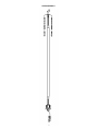
1
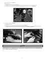
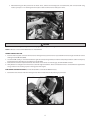
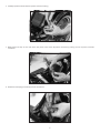
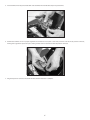
9-28-07
S&S Cycle, Inc
Copyright © 2007
235 Causeway Blvd.
La Crosse, Wisconsin 54603
Instruction 106-1544
by S&S® Cycle, Inc.
®
.
Phone: 608-627-1497 • Fax: 608-627-1488
All rights reserved.
Printed in the U.S.A.
Technical Service Phone: 608-627-TECH (8324)
Technical Service Email: [email protected]
Website: www.sscycle.com
Because every industry has a leader
Installation Instructions for S&S® VFI Knock Sensor Kit for
2001-'07 Delphi® Style VFI Module (with USB)
DISCLAIMER:
S&S parts are designed for high performance, off road, racing applications
and are intended for the very experienced rider only. The installation of S&S
parts may void or adversely affect your factory warranty. In addition such
installation and use may violate certain federal, state, and local laws, rules
and ordinances as well as other laws when used on motor vehicles used on
public highways, especially in states where pollution laws may apply. Always
check federal, state, and local laws before modifying your motorcycle. It is
the sole and exclusive responsibility of the user to determine the suitability
of the product for his or her use, and the user shall assume all legal, personal
injury risk and liability and all other obligations, duties, and risks associated
therewith.
The words Harley®, Harley-Davidson®, H-D®, Sportster®, Evolution®, and all
H-D part numbers and model designations are used in reference only. S&S
Cycle is not associated with Harley-Davidson, Inc.
SAFE INSTALLATION AND OPERATION RULES:
Before installing your new S&S part it is your responsibility to read and follow
the installation and maintenance procedures in these instructions and follow
the basic rules below for your personal safety.
Gasoline is extremely flammable and explosive under certain conditions
and toxic when breathed. Do not smoke. Perform installation in a well
ventilated area away from open flames or sparks.
If motorcycle has been running, wait until engine and exhaust pipes
have cooled down to avoid getting burned before performing any
installation steps.
Before performing any installation steps disconnect battery to eliminate
potential sparks and inadvertent engagement of starter while working
on electrical components.
Read instructions thoroughly and carefully so all procedures are
completely understood before performing any installation steps.
Contact S&S with any questions you may have if any steps are unclear or
any abnormalities occur during installation or operation of motorcycle
with a S&S part on it.
Consult an appropriate service manual for your motorcycle for correct
disassembly and reassembly procedures for any parts that need to be
removed to facilitate installation.
Use good judgement when performing installation and operating
motorcycle. Good judgement begins with a clear head. Don’t let
alcohol, drugs or fatigue impair your judgement. Start installation when
you are fresh.
Be sure all federal, state and local laws are obeyed with the installation.
For optimum performance and safety and to minimize potential
damage to carb or other components, use all mounting hardware that is
provided and follow all installation instructions.
Motorcycle exhaust fumes are toxic and poisonous and must not be
breathed. Run motorcycle in a well ventilated area where fumes can
dissipate.
••
••
••
••
••
••
••
••
••
IMPORTANT NOTICE:
Statements in this instruction sheet preceded by the following words are of
special significance.
WARNING
Means there is the possibility of injury to yourself or others.
CAUTION
Means there is the possibility of damage to the part or motorcycle.
NOTE
Other information of particular importance has been placed in italic type.
S&S recommends you take special notice of these items.
WARRANTY:
All S&S parts are guaranteed to the original purchaser to be free of
manufacturing defects in materials and workmanship for a period of twelve
(12) months from the date of purchase. Merchandise that fails to conform to
these conditions will be repaired or replaced at S&S’s option if the parts are
returned to us by the purchaser within the 12 month warranty period or within
10 days thereafter.
In the event warranty service is required, the original purchaser must call or
write S&S immediately with the problem. Some problems can be rectified by
a telephone call and need no further course of action.
A part that is suspect of being defective must not be replaced by a Dealer
without prior authorization from S&S. If it is deemed necessary for S&S to
make an evaluation to determine whether the part was defective, a return
authorization number must be obtained from S&S. The parts must be packaged
properly so as to not cause further damage and be returned prepaid to S&S
with a copy of the original invoice of purchase and a detailed letter outlining
the nature of the problem, how the part was used and the circumstances at
the time of failure. If after an evaluation has been made by S&S and the part
was found to be defective, repair, replacement or refund will be granted.
ADDITIONAL WARRANTY PROVISIONS:
(1) S&S shall have no obligation in the event an S&S part is modified by any
other person or organization.
(2) S&S shall have no obligation if an S&S part becomes defective in whole or in
part as a result of improper installation, improper maintenance, improper use,
abnormal operation, or any other misuse or mistreatment of the S&S part.
(3) S&S shall not be liable for any consequential or incidental damages
resulting from the failure of an S&S part, the breach of any warranties, the
failure to deliver, delay in delivery, delivery in non-conforming condition, or
for any other breach of contract or duty between S&S and a customer.
(4) S&S parts are designed exclusively for use in Harley-Davidson® and other
American v-twin motorcycles. S&S shall have no warranty or liability obligation
if an S&S part is used in any other application.
i
c
b
g
j
h
k
a
d
e
f
S&S® VFI Knock Sensor Kit and Replacement Parts
S&S VFI Knock Sensor Kit (Includes 55-1015 and 106-1300)..............106-0810
Knock Sensor Kit (Sensor and mounting hardware)................................55-1015
S&S VFI Knock Wiring Harness..................................................................... 106-1300
Note that the installation kit may vary slightly if purchased with a complete engine. Not all of the hardware used in the 106-0810 is required for specific
installations. This extra hardware will not be included in S&S engine packages.
Knock Sensor Mounting
WARNING
Prior to installation, disconnect and remove the battery, negative cable first. This will eliminate potential sparks and inadvertent
engagement of the starter while working on the motorcycle.
WARNING
Be careful not to damage the front of the tank when raising or removing it.
It is possible to install the knock sensor assembly and wiring harness without removing the fuel tank. Loosen (do not remove) the bolt at the front
of the tank, and remove the mounting bolt(s) at the rear of the tank. The rear of the tank then can be raised slightly, allowing enough room to install
these components.
NOTE - Clearances are limited at the front of the tank. Use care not to damage any painted surfaces while handling tank.
Installing components without removing the fuel tank is a timesaving suggestion only. If there is any reservation on the part of the installing
mechanic about performing this installation with the fuel tank in place, refer to the appropriate service manual for correct procedure for removing
fuel tank and related components.
CAUTION
•
•
The knock sensor must be mounted to the rear cylinder head for correct operation.
The knock sensor will provide an incorrect signal if mounted on the front cylinder head.
NOTE - There are two mounting locations possible for the knock sensor. Read the description of each location, and then examine your motorcycle for
which one to use. The first location has better clearance than the second. The knock sensor will work well in either location.
Location 1: Rear cylinder head, across from the temperature sensor on the front head. Some S&S® heads have an unused threaded hole in the rear
head near the intake port. Stock and some S&S heads do not have the unused threaded hole. If the extra threaded hole is present, install the knock
sensor there. See Step a on next page. If the threaded hole is not present, use Location 2.
Location 2: Top motor mount at the rear cylinder head attachment point. All stock heads and some early S&S heads do not have the unused,
threaded hole across from the temperature sensor, and must use the top motor mount location. See Step b on next page.
2
a. Knock sensor mounting at Location 1:
Rear cylinder head
1. Remove the plug from the rear head (if present).
2. Insert the 5/16 x 11/2" coarse thread bolt (f ) through the 5/16" lock washer (g), knock sensor (a), and 1/4" thick spacer (b).
3. Apply Loctite® (i) to end of the bolt and attach the assembly to the rear head. Torque to 11 ft-lb. See Picture 1.
Picture 1
b. Knock sensor mounting at Location 2:
Top motor mount location.
1. Remove the rear motor mount bolt from the rear cylinder head. See Picture 2.
2. Test fit the knock sensor mounting block (c) to the rear motor mount location using the 3/8" x 2" coarse thread bolt (d) and 3/8" lock
washer (h). Test fit the knock sensor to mounting block using bolt (e) and lock washer (g). See Picture 3.
Picture 2
Picture 3
CAUTION
Carefully place the fuel tank back into position to check the knock sensor and mounting block clearance. Position the mounting block
so that the knock sensor or mounting block does not contact the fuel fitting or any other part of the motorcycle. If the wiring harness or
outer body of the knock sensor (black plastic portion) contacts the engine or any other part of the motorcycle, it could damage the knock
sensor, or interfere with its ability to detect knock.
3
3. After determining the final position for the knock sensor, remove the mounting bolts and lockwashers, then re-install them using
Loctite® (i). Torque 3/8" x 2" mounting block bolt (d) to 33 ft-lbs and knock sensor bolt (e) to 11 ft-lbs.
Picture 4
CAUTION
Hold the knock sensor in position by hand while torquing. Do NOT use pliers. Damage to the knock sensor will occur.
NOTE - Red Loctite® is not recommended for fasteners into aluminum.
Wiring Harness Routing
1. Connect the black, plastic connector of knock sensor wiring harness (k) to knock sensor (a) to determine harness length available to route to
the Engine Control Module (ECM).
2. Locate the ECM. Usually, it can be found under the right side cover (Touring models) or under the seat (Harley-Davidson® Softail® and Dyna™).
Consult your factory manual if you are unable to locate the ECM.
3. Route the wire so that the exposed terminals of the knock sensor harness are near the gray, 36-terminal ECM connector.
4. Verify that there is enough slack in the harness to allow for engine movement. Also be sure that the harness is secured with the supplied wire
ties (j) so that it is not touching any hot or moving parts of the engine.
ECM Connector Modification (Insertion of knock harness terminals into ECM connector).
1. Cut the wire tie at the base of the main wiring harness where it meets with the 36-position gray connector.
Picture 5
4
2. Carefully open the backside of the 36-position connector housing.
Picture 6
3. Gently release the clips on each side of the clear plastic cover on the 36-position connector by pressing on each clip with a small flat
screwdriver.
Picture 7
4. Remove the socket plugs in terminal positions #16 and #34.
Picture 8
5
5. Insert the white wire into position #34. Next insert the white wire with the blue stripe into position #16.
Picture 9
6. Confirm the terminals are all in proper alignment and reinstall the clear plastic cover. Next, close the cover of the 36-position connector,
making sure to get all the clips back in place. Finally, reinstall a wire tie at the base of the 36-position connector.
Picture 10
7. Plug the 36-position connector into the VFI module and the installation is complete.
6
Wiring Harness
7
Because every industry has a leader