1
TECHNICAL
SERVICE MANUAL
OPERATION, SERVICE AND REPAIR
of
c. c. w.
ENGINES
Models
C. C. W. 340 & C. C. W. 400 ·
NOVEMBER 1970
PRINTED IN CANADA
CANADIAN CURI/SS-WRIGHT, LIMITED
500 CARUNGVIEW DRIVE, REXDALE, ONTARIO
PHONE: 677-3930- TELEX: 02-29647
..
•
I
:'
'
LIST OF ILLUSTRATIONS
F IGU RE
NUMBER
1-1
2-1
2-2
2-3
2-4
2-5
2-6
2-7
2-8
FIGURE
NUMBER
PAGE
TITLE
MODEL K EC 340/400 ENGIN E LEFT SIDE . .. . . .. 1-2
T WO STROK E ENGIN E OPE RATING PR INCIPLE . . . . .
SAWA FUJI I G N ITION SYSTEM . .. .... . . .. . . .... 2-3
KO KUSAN I G NIT ION SYSTEM . . .. ... . . ... . . . . . 2-3
L I GHTING SY STEM-MANUAL START. Previous to
Engine Serial Numbers 340-2903614 and 400-2809570.
Light taken from l ighting coil. (AC 12 V 35W) . . .. . . 2-5
LI GHTING SY ST EM-EL ECTRIC STA RT . Previous t o
Engine Serial Numbers 340-2903614 and 4 00 -2809570 .
Lights powered from battery . . ... .. ... .... . . .. . . 2-5
LIGHTIN G SY STEM- MANUAL START. 340S only
previous to serial number 340-2903614.
L ights taken from lighting coil. (AC 12V 75W). . .. .. 2-6
LI GHTING SY ST EM-MANUAL START. Engine
Serial Numbers 340·2903614, 400-2809570 and
subsequent.
One Headlamp. 12 volt, 35 watts.
One Tai l lamp, 12 volt, 3 watts. . ..... . ... . . ... . . 2-8
LI GHTING SYSTEM - MANUAL START . Engine
Serial Numbers 340-2903614, 400-2809570 and
3-2
3-3
3-4
3-5
3-6
3-7
3-8
3-9
3-10
3-11
3-1 2
4-1
4-2
4-3
4-4
4-5
4-6
4 -7
4-8
5-1
subsequent.
Two Headlamps, 12 volt, 35 watts.
Two T aillamps, 12 volt,. 3 w atts. . . . . .
. . . . . . . . 2·9
2-9 LIGH T ING SY STEM- EL ECT RIC START. Engine
Serial Numbers, 340-2903614,400-2809570 and
subsequent.
One or two head and tail lamps.
Battery charging. . . .
. . ....... . .. .. . .. . . . ... 2-1 0
2-10 TYPI CAL WIRING SCHEMATIC.
8 POLE CONNECTOR, MANUAL START. .. .... . .. 2-11
5-2
5-3
5-4
5-5
5-6
5-7
5-8
5-9
2-11 TYPICAL WIRING SCH EMATIC.
8 POLE CONNECTOR, E L ECTRIC START. ..... . .. 2-12
2-1 2 TYPI CAL WIRING SCHEMATIC. 340's ONLY.
6 POLE CONNECTOR, MANUAL START . . . .. .. . . 2-13
2-12A TYPI CAL WIRING SCHEMATI C. 340-G-E,
5-10
5-11
5-12
5-13
5-14
6 POLE CONN ECTOR, MANUAL START. ... .. . ... 2 -14
2-1 3 TYPICAL WIRING SCHEMATIC.
6 POLE CONNECTOR, ELECTRIC START .. .. . . . . . 2-15
3-1 CYLINDER COVER REMOVED ... .. . .. . . . ... . . . 3-2
TIT LE
PAGE
INTAKE AND EXHAUST MANIFOLDS REMO VED . 3-2
RECOIL STARTER AND HIGH T EN SION
COILS REMOVED . .. ... . . .. . ... . .. . . . ... .. . . . 3-2
STARTER CUP AND FAN BELT PULL EY . . . .. . . . 3-3
FAN COVER REMOVED . . ..... . . . . .. . . .. ... . . 3-3
REMOVING FLYWHEEL . . . . .. . .. .. . .. . . .. . .. . 3-4
FAN COVER CASE REMOVED .. . . . . .. ... . . . . .. 3-4
MAGNETO REMOVED .. . .. .. ..... .. ... . . . ... . 3-5
CYLINDER HEADS REMOV ED .. . . . .. . .. . . . .... 3-6
CYLINDERS REMOVED .... ... ... .... .. .... .. 3-6
REMOVING PISTONS . .. .... . . .. . . ... .. .. ..... 3-8
UPPER CRANKCASE HALF R EMOVED . . . . . . . .. . 3-8
FAN COVER A SSEMBLY . .. .. . .. . ... . ..... . .. . 4-2
RECOIL STARTE R A SSEMBLY .. .. .. . . . .. .. . . .. 4 -3
FLYWHEEL ASSEMBLY (340S) . .... . .. . . .. .. . . . 4 -4
FLYWHEEL ASSEMBLY (340, 340G, 400) .. ..... . 4-6
STATOR A SSEMBLY (Sawafuji Ignitio n) . . . . . . ... . 4 -7
STATOR ASSEMBLY (Kokusan Ignition) . . . . ... .. . 4 -8
PISTON AND CRANKSHAFT A SSEM BLY . . . .. . .. 4-9
OIL SEALS IDENTIFICATION . . ... . .. . . .... . .. . 4-9
CRANKCASE LOWER HALF (Oil seal retaining circlips
· · · · · · · · · · .. . . . ... . . .... .. . . . . . . . . . . ..... .. 5-1 I
CRANKCASE BOLT T ORQUING SE QU EN CE . . ... . 5-2 ·
INSTALLING PISTON, R INGS AND PINS . ... . .. . . 5-2
INSTALLING CYLINDERS ... . .• ....... .. .. .. . 5-3
CYLINDER HOLD-DOWN NUT TORQUING
SEQUENCE . . .... . . . .. . ... . .. . . . . . . . ... . ... . 5 -3
INSTALLING CYLINDER HEADS . .. ... .. . . .. . . . 5-4
CYLINDER HEAD HOLD-DOWN NUT TORQUING
SEQUENCE . ... .. .. . . ..... . . . .... .. . .. . .... . 5-4
STATOR ASSEMBLY INSTALLED . . . . .. . .. . .. . . 5-5
FAN COVER BACKING PLATE AND
FLYWHEEL INSTALLED ....... . .• .. ... . ... . 5-5
FAN COVER, STARTER CUP AND FANBEL T PULLEY
INSTALLED ..... . . ... . . . . ... . . . .... . .. . . . . . 5-6
HIGH TENSION IGNITION INSTALLED . . ... . . .. . 5-6
RECOIL STARTER INSTALLED .. .. .. . .. . . .. .. . 5 -6
ADJUSTING CONTACT BREAKER POINTS . . .. .. . 5-8
ADJUSTING ENGINE IGNITION TIMING .. .. .. . .. 5-9
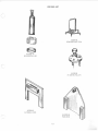
C.C.W. TOOL LIST . . .. ... .. . . . .. . . . .. .. . . . .. . 1-3
/
LIST OF TABLES
TABLE
NUMBER
TITLE
PAGE
1-1
2-1
2-2
3-1
5-1
5-2
TECHNICAL DATA . .... ... . . ....... .. .... . . .
TROUBLESHOOTING CHART .. . . .. . . . .. . ... ...
LUBRICATION CHART .. . . . . ... . . . .... . . . ...
FITS AND TOLERANCES . . ... . .. .. . . . .. .. . . .
CRANK VERSUS PISTON ANGL E ...... .... . .. ..
TORQUE SPECIFICATIONS . . .. ..
1-1
2-16
2-20
3-10
5-9
5-10
5-3
METRIC/LINEAR CONVERSION FORMULAS .
5-10
5-4
LIST OF APPROVED CARBURETORS
o
•
•
0
0
0
0
0
.
0.
0
0
0
o
0
o
0
0
0
••
••
0
0
•
o.
5-10
TABLE OF CONTENTS
SECTION
PAGE
INTRODUCTION AND TECHNICAL DATA . .... .
Introduction .... ... ... .. .. . .. . . . ....
1.1
1.6
Model Designation . . ..... .............
Technical Data ............... . ......
1.8
1.9
Tools, Special & Standard Requirement ...
ILLUSTRATION OF SPECIAL TOOLS . . ..... . ..
II
Ill
OPERATION AND SERVICE INSTRUCTIONS .. .. 2-1
Principles of Operation ...... . ...... . .. 2-1
2.1
Sequence of Operation ....... .. . . . . . .. 2-1
2.2
Ignition Systems ...... ............. . . 2-2
2.3
General .......... ...... .. .. . . . . . .. . 2-2
2.3.1
Description . . ........... .. . . . ..... . . 2-2
2.3.2
2.3.2.1 Sawafuji Ignition (Magneto) . . ...... . ... 2-2
2.3.2.2 Kokusan Ignition (Magneto) . . . . . .. .. ... 2-2
Operation . .. . . . . ... . .. . .. . ...... . . . 2-2
2.3.3
Detonation and Pre-Ignition ...... . . .... 2-2
2.4
Pre-Ignition ...... . . . . ........ . . . . .. . 2-4
2.4.4
LIGHTING SYSTEMS .... .. ... . . . . ... 2-4
2.5
Operation of Lighting Systems . ....... . . 2-4
2.5.2
2.5.2.1 Engines previous to Serial Numbers Model3402903614 and Model 400-2809570 ... ... . 2-4
2.5.2.2 Engines Serial Numbers Model 340G-E 2903614 and Model 400-S-G-E 2809570
and subsequent . . . . . ..... ... ..... . . .. 2-4
2.5.2.3 Model 340S only. Engines with serial numbers
2903614 & subsequent. See fig. 2-12 .. . .. 2-7
2.6
PERIODIC SERVICING ........... . ... 2-7
Spark Plugs . . .. .......... . . . ... . ... . 2-7
2.6.1
Fan Belt .......... . .. ...... . . . . ... . 2-7
2.6.2
Trouble Shooting .... ... ..... . .. . ... . 2-7
2.6.3
2.7
OPERATING INSTRUCTIONS . .... ... 2-19
Starting the Engine ..... . . .... _ . . .. . . 2-19
2.7.2
2.7.2.1 Starting with recoil starter ..... . . . . .... 2-19
2.7.2.2 Starting with electric starter .. . . . ... . . . 2-19
Stopping the Engine _..... .. .... . .... 2-19
2.7.3
2.8
Lubrication .......... ... ....... . ... 2-19
DISASSEMBLY, CLEANING AND INSPECTION .. . 3-1
3.1
PREPARATION FOR DISASSEMBLY .... 3-1
3.2
DISASSEMBLY ................ .. ... 3-1
3.3
CLEANING AND INSPECTION ... ... ... 3-7
Cleaning ..................... ...... 3-7
3 .3.1
3.3.2
Inspection ...... . ....... .. . ... . . . ... 3-7
General ..... . ........ . .. . ..... ..... 3-7
3.3.3
Spark Plugs ... . .......... . .......... 3-7
3.3.4
3 .3.5
Fan Cover .. . . . . .. .......... . .. . ... . 3-7
Recoil Starter . . ..... . . . .. .. . .. . . . ... 3-7
3.3.6
Electric Starter . . . ... ...... . . .. . _ .. . . 3-7
3.3.7
Magneto Assembly ... . .. .. . ........ .. 3-7
3.3.8
PAGE
SECTION
1-1
1-1
1-1
1-1
1-1
1-1
IV
3 .3 .9
3 .3 . 10
3.3.11
3.3.12
3 .3 . 13
3.3.14
Flywheel Assembly . . . . . . .. ... . . . . . ...
Cylinder Heads and Cylinders . .. . ... . ...
Pistons, Pins and Rings .... . . .. .. .. .. . .
Crankshaft and Connecting Rods . .... . . .
Crankcase .. ..... .. .. . .. . . .. . .. . .. ..
Fits and Tolerances .. _. . .. . ..... .. ....
REPAIR
4.1
4.2
4.3
4.4
4.5
AND REPLACEMENT .... ........ . . .. 4-1
GENERAL .............. ... ........ 4-1
FAN COVER .... ... . ... .... . ...... . 4-1
RECOIL STARTER . .. .... . ..... ..... 4 -1
FLYWHEEL ASSEMBLY (340S) . . . . . ... 4-5
FLYWHEEL ASS EMBLY (340E, 340G,
400) ..... - .... . .. ... .. . - . . . . . . . . . . 4-5
STATOR ASSEMBLY (340S) . . . .. ... . . . 4-5
Contact Breaker Point Set . ..... . .. . . . . . 4-5
Condenser and Oil Felt Pad .. .. . . . . .. . . 4-10
STATOR ASSEMBLY (340E, 340G, 400). 1-10
Contact Breaker Point Set .. ........ ... 4-10
Condenser and Oil Felt Pad ......... . .. 4-10
CRANKSHAFT .. .... ..... . .... .... . 4 -10
Oil Seal and Outer Bearing . ... ... .. ... 4-10
4.6
4.6. 1
4 .6 .2
4.7
4.7.1
4.7.2
4 .8
4.8. 1
v
3-9
3-9
3-9
3-9
3-9
3-9
REASSEMBLY, TESTING AND ADJUSTMENTS . . 5-1
GENERAL ... ..... ....... ..... . . . .. 5 -1
5.1
5.2
REASSEMBLY .. ... . .. .... . ...... ... 5-1
5.2.1
Crankcase and Crankshaft . .... _ . . ... .. . 5-1
Pistons, Pins and Rings .. .... .... . . .... 5-1
5.2.2
5.2.3
Cylinders . .. ..... .. . .. .. ... . . .. . . . . . 5-2
Cylinder Heads .. . .. . . . . . . . ... . .... . . 5-4
5.2.4
Stator Assembly . . . . ..... . . . . .. . ... .. 5-5
5.2.5
Fan Cover Case and Flywheel .... . .. . . .. 5-5
5.2.6
Fan Cover, Starter Cup and
5.2.7
Fan Belt Pulley ......... . _... . . _ . . . .. 5-6
Electric Starter ....... . .... . .. ...... . 5-7
5.2.8
High Tension Ignition .. . . . .... ........ 5-7
5.2.9
Recoil Starter ........... . .. . . . ...... 5-7
5.2. 10
Intake and Exhaust Manifolds ...... ... .. 5-7
5.2.11
5.2.12
Covers . . .. . . . ....... .. .. . ..... . .... 5-7
5.2.13
Engine Installation .. . ....... . ... .. . .. 5-7
5.3
TESTING AND OVERHAUL .. . . . .... .. 5-7
ADJUSTMENTS . . . .... .. ..... ... .... 5-7
5.4
Carburetor ............... .. .. .... ... 5-7
5.4.1
Spark Plugs . . .. ..... .... . . ... . ...... 5-7
5.4.2
Contact Breaker Point .... . . ........ ... 5-7
5.4.3
Engine Ignition Timing .... . . . ........ . 5-7
5.4.4
5.4.4.1 Preferred Method ... .. ... . _ ... . ...... 5-7
5.4.4.2 Alternate Method .. . . . ....... . .. .. .. . 5-8
5.4.4.3 Crankshaft Angle Versus Piston Travel .... 5-8
SECTION 1
c
INTRODUCTION AND TECHNICAL DATA
1.1 INTRODUCTION
NOTES
a. Model 340S includes a Sawafuji ignition system comprising of one low tension generati ng coil and two high tension
coils of opposite polarity. This system is not interchangeable with other models.
1.2 This manual co nta ins instructions for the operation,
service, and repair of Canadian Curtiss-Wright CCW 340 and
CCW400 two cycle engines.
b. Models 340E, 340G, and 400 includes a Kokusan ignition
system comprising of two low tension generating coils and
two high tension coils all of the same polarity. This system
may be interchanged between all models excepting 340S.
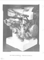
1.3 The model CCW340/400 engine is shown in Figure 1-1.
One illustration is used, since the two engines are sim ilar in
external appearance. These engines are designed for use in
various snowmobi le configurations and are suitable for use in
All Terrain Vehicles or simil ar app lications.
c. The model 400 uses a smaller fan pulley than the 340
models and has an increased bore size to 65 mm . The piston
stroke is the same in both engines.
1.4 The instructions deta il the procedures and tools required to ensure effic ient operation, servicing and repair of
the engine and component parts. Refer to Parts Catalogue for
tool cross-reference.
Engine nuts, bolts and threads are metric except for the
engine mounting bolts, which are 7/ 16" SAE coarse, and the
power take off (P.T.O.) end of the crankshaft which is 1/2"
SAE fine (20TPI).
1.8 TECHNICAL DATA
Table 1-1 details specificatio ns appl icable to the models
CCW 340 and CCW 400 engines.
1.5 Carburetion data for the engine models covered in this
manual is detailed under sepa rate instructions. For carburetor technical requirements refer to Appendix I, or to
applicab le manufacturer's specifications.
1.9 TOOL REQUIREMENT
The following is a list of too ls required for the overhaul and
adjustment of models CCW 340 and CCW 400 engines:
1.6 MODEL DESIGNATION
a. Special Tools
1.7 The letters and numbers in the subject engine models
designate the following: -
ccw
340/400
--...
..._.
Manufacturer's type designation.
Cubic centimeter displacement
- S Manual Start
- E Electric Starter
- G Geared flywheel (for subsequent electric
starter installation.
SER IAL NOS.
COMMENC IN G
MODEL
YEAR
18
19
28
29
ccw 400
ccw 340
ccw 400
ccw 340
1969
1969
1970
1970
Reference
Tool, Flywheel puller Part 43-0790-90
Para. 3.2. 1 ( 1)
Tool, Main Spring, Starter Rewind. 43-0797-60
Para. 4.4
Tool, Bearing puller (crankshaft). Part 43-0791 -70 Para. 4.8.1
Tool, Flywheel Locking. Part43-0798-40
Para. 3.2.1(j)
Tool, Fan Pulley Locking. 43-0792-50
Para. 4.2.1 (a)
b. Standard Tools
10/13 mm spanner
13/21 mm Box spanner and hand le
22 mm spanner
22 mm socket wrench and ratchet
Piston ring removal tool
Piston ri ng compresso r
Piston ring groove cleaning tool
Circlip removal tool
Torque wrench (pounds feet)
Dial indicator
Degree whee l
1-1
Feeler Gauge
Spark plug tap
Spark plug wire gauge
Thread Cleaning tools
Wire brush (spark plugs)
Soft metal (non ferrous)
scraper
Ph ill ips screw driver set
Common screw drivers
Soft hammer
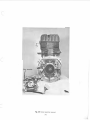
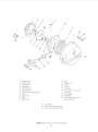
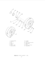
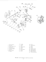
Fig. 1-1 Model KEC 340/400 Engine - Left Side View from Flywheel end .
1-2
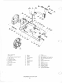
CCWTOOLLIST
43-0797-60
REWIND SPRING TOOL
43-0791-70
BEARING PULLER
c
43-0790-90
FLYWHEEL PULLER
43-0798-40
FLYWHEEL LOCK
43-0792-50
FAN LOCK
1-3
TABLE 1-1
TECHNICAL DATA -1970 MODELS
SECTION I
SPECIFICATION
ccw 340
ccw 400
Cycle:
Two stroke
Two
339 cc (20.9 cu .in.)
60 mm (2.36 in.)
60 mm (2.36 in.)
8.5
25 BHP at 5800 rpm
(23 lbs. ft.) at 5250 rpm
Two stroke
Two
398 cc (24.3 cu. in.)
60 mm (2.36 in.)
65 mm (2.56 in.)
8.5
30 BHP 5800 rpm
(27.31bs. ft.) at 5500 rpm
400 gr/ps.h (0.881b/ps.h)
Auto-advanced flywheel ignition
with lighting coii12V- 75W
0.3 to 0.4 mm (.012 to .016 in.)
400 gr/ps.h (0.881b/ps.h)
Auto-advanced flywheel ignition
with lighting coii12V- 75W
0.3 to 0.4 mm (.0 12 to .016 in.)
230 BTDC
go (.015" BTDC on Piston)
NGK B 8H or equivalent
0.5 to 0.6 mm (0.020 to 0.024 in.)
Rewind starter with emergency
starting pulley or electric starter
(output 0.5 kw)
Tillotson HR or equivalent
Mixture, gasoline of known brand
and special air cooled two stroke
engine oil. (See Table 2-2)
20:1 (at normal operating conditions)
Left hand (standard configuration)
see toward the power take off end
of the engine.
60 lbs.
1380
23mm
42mm
1680
23mm
28mm
67mm
1
1
16.35 cc
8
1.81 : 1
Sawafuji
Kokusan
Sawafuji
.4 ohms
8,500 ohms
1.75/2.25 amps
8 mm @500 RPM
15 mm@ 5,500 RPM
230 BTDC
so (.015" BTDC on Piston)
NGK B SH or equivalent
0.5 to 0.6 M.M. (0.020 to 0.024 in.)
Rewind starter with emergency
starting pulley or electric starter
(output 0.5 kw)
Tillotson HR or equivalent
Mixture, gasoline of known brand
and special air coo led two stroke
engine oil. (See Table 2-2)
20:1 (at normal operat ing cond it ions)
Left hand (standard configuration)
see toward the power take off end
of the engine.
60 lbs.
1380
23mm
46mm
1680
23mm
38 mm
67mm
1
1
17 cc
8
t81 :1
Kokusan
Kokusan
Kokusan
1.4 ohms
5,500 ohms
1.5/1.75 amps
9 mm @500 RPM
16 mm @5,500 RPM
Number of cylinders:
Capacity :
Stroke:
Bore:
Compression ratio :
Rating:
Maximum torque :
Specific fuel consumption
under full load:
Ignition system:
Contact breaker gap :
Ignition timing setting
when fully advanced :
(Static timing setting): BTDC
Spark Plug :
Spark plug gap:
Starter system :
Carburetor:
Fuel:
Mixture ratio :
Rotation direction of engine:
Weight:
Inlet port, timing
height
width
Exhaust port, timing
height
width
Piston height:
Piston ring, chromium plate, top
Piston ring, gray cast-iron, bottom
Cylinder head, volume
Cooling fan, blades
ratio
Magneto, make 340S only
340 GE
IGNITION COILS (340S)
Resistance, primary
Resistance, secondary
Current rating
Spark in free air
(three need le gap)
1-4
0.
TABLE OF CONTENTS
SECTION
PAGE
II
Ill
OPERATION AND SERVICE INSTRUCTIO N S .. . . 2-1
2.1
Principles of Operation .. . : • ..... . .. . .. 2-1
Sequence of Operation ... . . . .... ..... . 2-1
2.2
Ignition Systems . . . .. .. .. . ... . . . ... . . 2-2
2.3
General .... ... . . . . .. .. . ...... . .... . 2-2
2.3.1
Description . ... .. . .. .... .. ... . ..... . 2-2
2.3.2
2.3.2.1 Sawafuji lgnitfon (Magneto) .. . ... . . . . . . 2-2
2.3.2.2 Kokusan Ignition (Magneto) . . ... . . . . .. . 2-2
Operation .. . . . . ........ . . . . . . .. .. .. 2-2
2.3.3
Detonation and Pre-Ignition . . . .. . ... ... 2-2
2.4
Pre-Ignition . . . ..... . ...... . .... . ... . 2-4
2.4.4
LIGHTING SYSTEMS .. . .. . ... . . .... . 2-4
2.5
Operation of lighting Systems . . .. . . . ... 2-4
2.5.2
2.5.2.1 Engines previous to Serial Numbers Model3402903614 and Model 400-2809570 . ...... 2-4
2.5.2.2 Engines Serial Numbers Model 340G-E 2903614 and Model 400-S-G -E 2809570
and subsequent . . . .. . ... . .. . . . .. .. . . . . 2-4
2.5.2.3 Model 340S only. Engines with serial numbers
2903614 & subsequent. See fig. 2-12 . .... 2-7
PERIODIC SERVICING ... . ..... . . ... . 2-7
·2.6
Spark Plugs . . ... . .. · . . ..... .. . .. . .... 2-7
2.6. 1
Fan Belt . .. ... .... .. ........ . . . . .. . 2-7
2.6.2
Trouble Shooting ....... . . . . . . . .. .... 2-7
2.6.3
OPERATING INSTRUCTIONS ....... . 2-1 9
2.7
2.7.2
Starting the Engine .. . .. ... ... . . . ... . 2-19
2.7.2.1 Starting with recoil starter . . ... . . . .. . .. 2-19
2.7 .2.2 Starting with electric starter .. . . .. . .... 2-19
2.7.3
Stopping the Engine ............. .. .. 2-19
2.8
lubrication .. . ... .. .. . . .. . .. .. ..... 2-1 9
DISASSEMBLY, CLEANING AND INSPECTIO N . .. 3-1
PREPARATION FOR DISASSEMBLY .. . . 3-1
3.1
3 .2
DISASSEMBLY ...... .. ...... .. ... .. 3-1
3.3
CLEANING AND INSPECTION .. ... ... . 3-7
3.3. 1
Cleaning .. . ... . . . . ...... ... . . ..... . 3-7
3.3 .2
I nspecti o"n ... . . . . ... . .. . . ... .. .. . . . . 3-7
3.3.3
General ................ . .. .. .... . . . 3-7
3.3.4
Spark Plugs .......... .. . . . . .. . . . .... 3-7
3.3.5
Fan Cover ........ .. . .. . . . . . ... . . . .. 3-7
3.3.6
Recoil Starter . . . . . ... . ... .. . . .. . . . .. 3-7
Electric Starter . . . .... . . .. ..... . .. .. . 3-7
3.3.7
M agneto Assembly . . .... . ... .. ....... 3-7
3.3.8
PAGE
SECTION
INTRODUCTION AND T ECHNICAL DATA .. .. . . 1-1
1.1
Introduction ....... ..... ... ..... .... . 1-1
1.6
Model Designation .. .... . ...... .... .. . 1-1
1.8
Technical Data ... ... .... . ......... .. 1-1
1.9
Tools, Special & Standard Requirement .. . 1-1
ILLUSTRATION OF SPECIAL TOOLS . . .. ... . . . 1-1
IV
3.3 .9
3.3. 10
3.3 . 11
3.3. f2
3.3 .13
3.3. 14
F ly wheel Assembly .... .. . . . . . . ... . .. .
Cylinder Heads and Cylinders . ..... .. ...
Pistons, Pins and Rings .. . . . . . . .. . .. . :.
Crankshaft and Connecti ng Rods ...... . .
Crankcase . ... . ........... .. . . . .. ...
F its and T olerances . .. . . . . . . .. . .. .... .
REPA I R
4.1
4.2
4.3
4.4
4.5
AND REPLACEM EN T ... _ . ... .. . ... . . 4-1
GENE RA L . . ... . .. . ... .. ........... 4-1
FAN COVER ... . ............ _ . ." .... 4-1
RECOIL STARTER •.. .. . . ..... ... .. . 4 -1
FlYWH EEL ASSEM B LY (340S) ... _ ... . 4 -5
F lYWH EEL A SSEM B L Y (340E, 340G,
400) . .. · ... . . . ...... . . . . . .... . ... . . 4-5
STAT OR ASSEM BL Y (340S) . .. .. .. . . _. 4-5
Contact Breaker Point Set .. . . . . ... . ... . 4-5
Condenser and Oi l Felt Pad . .... .. ... .. 4-10
STATO R ASSEMBL Y (340E, 340G, 400 ) . 1-10
Contact B rea~er Point Set . . . . .. .. . ... . 4 -10
Condenser and Oi l Felt Pad . .. .. .. .. . . . 4-10
CRANKSH A FT .. . . .... . ." . ... . ...... . 4 -10
Oil Seal and Outer Bearing ... . .. . .... . 4- 10
4.6
4.6.1
4.6.2
4.7
4.7.1
4. 7.2
4.8
4.8.1
v
3-9
3-9
3-9
3-9
3-9
3-9
REA SSEMBLY, T ESTING AND ADJUSTMENTS .. 5-1
!,).1
GENE RAL . ... ... . ... ... ........... 5-1
5.2
REASSEMBLY .·.. .... .... .... . ... ... 5-1
5.2.1
Crankcase and Crankshaft . . ..... . ... . .. 5-1
Pistons, Pins and 13 ings ... . . .. .. . .. . . . . 5-1
5.2 .2
Cyl inders .. .. . . ... . ... .... .. : ." . . . . .. 5-2
5.2.3
Cyl inder H eads . ... .. . . . . ..... . ..... . 5-4
5.2.4
Stator Assembly . .... . .. . . . . . . .. . . . .. 5-5
5.2.5
Fan Cover Case and Flywheel ... . . .. . ... 5-5
5.2.6
Fan Cover, Starter Cup and
5.2.7
Fan Belt Pulley . . . . .... . ..... . . . . . . . . 5-6
Electric Starter ........ . .. . .. .. , . . .. . 5-7
5.2.8
High Tension Ign it ion .. . . ... ... ... . • .. 5-7
5.2.9
Reco il Starter .. . .. . . . ... .. . .. .. .. .... 5-7
5.2. 10
Intake and Exhaust Man.ifolds .... . . .... . 5-7
5.2.11
Covers . ... .......... .. . . ... .... . .. . 3-7
5.2.12
Engine Installation . . ... .. .... . . . . . . . . 5-7
5.2.13
TESTING AND OVERHAUL .. ...... ... 5-7
5.3
ADJUSTMENTS ....... .. .... . ..... .. 5-7
5.4
Carburetor . .. . . . ...... . ... . .... . . : .. 5-7
5.4.1
Spark Plugs .. . . .... . . .. . . ... . . . . ... . 5-7
5.4.2
Contact Breaker Point ... . . .. ......... . 5-7
5.4.3
Engine Ignition Timing . . . .. .. .... . .. .. 5-7
5.4.4
5.4.4.1 Preferred Method .. . . ..... . . . . ... . ... 5-7
5.4.4.2 Alternate Method .. . ... . . . .. . ... . . .. . 5-8
5.4.4.3 Crankshaft Angle Versus Piston Travel. .. . . 5-8
LIST OF ILLUSTRATIONS
FIGURE
NUMB ER
1-1
2-1
2-2
2-3
2-4
2-5
2-6
2-7
2-8
TITLE
FIGURE
NUMBER
PAGE
MODEL KEC 340/400 ENGIN E LEFT SIDE ....... 1-2
TWO STROKE ENGINE OPERATING PRINCI PLE .. .. .
SAWAFUJI IGNITION SYSTEM .. . .. ... ......... 2-3
KOKUSAN IGNITION SYSTEM .... .. ......... . . 2-3
LIGHTING SYSTEM - MANUAL START. Previous to
Engine Serial Numbers 340-2903614 and 400-2809570.
Light taken from lighting coil. (AC 12V 35W) . ..... 2·5
LIGHTING SYSTEM-ELECTRIC START. Previous to
Engine Serial Numbers 340-2903614 and 400-2809570.
Li ghts powered from battery ......... . ... . .... .. 2-5
LIGHTING SYSTEM -MANUAL START. 340S only
previous to serial number 340-29036 14.
Lights taken from lighting coil. (AC 12V 75W). . .... 2-6
LIGHTING SYSTEM-MANUAL START. Engine
Serial Numbers 340-2903614, 400-2809570 and
subsequent.
One Headlamp. 12 volt, 35 watts.
One Tail! amp, 12 volt, 3 watts. . . . . . . . ..... . ... . 2·8
LIGHTING SYSTEM- MANUAL START. Engine
Serial Numbers 340-2903614, 400-2809570 and
3-2
3-3
3-4
3-5
3-6
3-7
3-8
3-9
3-10
3-11
3-12
4-1
4-2
4-3
4-4
4-5
4-6
4-7
4 -8
5-1
subsequent.
Two Headlamps, 12 volt, 35 w atts.
2-9
Two Taillamps, 12 volt,. 3 watts. . .... . .
2-9 LIGHTING SYSTEM-ELECTRIC START. Engine
Serial Numbers, 340-2903614,400-2809570 and
subsequent.
One or two head and tail lamps.
.. .. 2·10
Battery charging. . . . . .. .... .... . . .
2-10 TYPICAL WIRING SCHEMATIC.
8 POLE CONNECTOR, MANUAL START. . ........ 2-11
5-2
5-3
5-4
5-5
5-6
5-7
5-8
5-9
2-11 TYPICAL WIRING SCHEMATIC.
8 POLE CONNECTOR, ELECTRIC START ..... . . .. 2-12
2-12 TYPICAL WIRING SCHEMATIC. 340's ONLY.
6 POLE CONNECTOR, MANUAL START ......... 2 -13
2-12A T YPICAL WIRING SCHEMATIC. 340-G-E,
5-10
5-11
5-12
5-13
5-14
6 POLE CONNECTOR, MANUAL START . .... . .. .. 2-14
2-13 TYPICAL WIRING SCHEMATIC.
6 POLE CONNECTOR, ELECTRIC START ..... .. .. 2 -1 5
3-1 CYLINDER COVER REMOVED . .. .. ... ....... .. 3-2
TITLE
LIST OF TABLES
TABLE
NUMBER
1-1
2-1
2-2
3-1
5-1
5-2
5-3
5-4
TITLE
PAGE
INTAKE AND EXHAUST MANIFOLDS REMOVED . 3-2
RECOIL STARTER AND HIGH TENSION
COILS REMOVED . ..... . . ... . . ... . ........ ... 3-2
STARTER CUP AND FAN BELT PULLEY .... . . . . 3-3
FAN COVER REMOVED . . .. . . ..... . . .... . .... 3-3
REMOVING FLYWHEEL .. .. . ... .... . . .. .. . ... 3-4
FAN COVER CASE REMOVED . .......... . .... . 3-4
MAGNETO REMOVED . ..... . ... . .... . . . .. .... 3-5
CYLINDER HEADS REMOVED . ....... . . .. ... . . 3-6
CYLINDERS REMOVED . . .. . . .. ..... . . . .. .. . . 3-6
REMOVING PISTONS ..... . .. . .. .... ... ... . ... 3-8
UPPER CRANKCASE HALF REMOVED .... . . .... 3-8
FAN COVER ASSEMBLY . . . . .. .. . ..... . .... . .. 4-2
RECOIL STARTER ASSEMBLY ...... .. . ........ 4-3
FLYWHEEL ASSEMBLY (340S) . .. .... .. .. .. .. .. 4 -4
FLYWHEEL ASSEMBLY (340, 340G, 400) ........ 4-6
STATOR ASSEMBLY (Sawafuji Ignition) . .. . .. .. .. 4-7
STATOR ASSEMBLY (Kokusan Ignition) . . . . . ..... 4 -8
PISTON AND CRANKSHAFT ASSEMBLY ... .' . ... 4 -9
OIL SEALS IDENTIFICATION . ... . .... .. . .. .... 4-9
CRANKCASE LOWER HALF (Oil seal retaining circlips
. . .. .. ... . ....... . .. . . . .. . ........ . ....... . 5-1
CRANKCASE BOLT TORQUING SEQUENCE .. . . .. 5-2
INSTALLING PISTON, RINGS AND PINS .. .. .... . 5-2
INSTALLING CYLINDERS . . ........... . . .... . 5 ·3
CYLINDER HOLD-DOWN NUT TORQUING
SEQUENCE ........ ... .... ..... ... ... . ..... . 5-3
INSTALLING CYLINDER HEADS ...... .... ..... 5-4
CYLINDER HEAD HOLD-DOWN NUT TORQUING
SEQUENCE .... .. .. . . . .... . ... ..... . ... ..... 5-4
STATOR ASSEMBLY INSTALLED . .. .... ... .... 5-5
FAN COVER BACKING PLATE AND
FLYWHEEL INSTALLED . .... ..... .... .. . . . . 5-5
FAN COVER, STARTER CUP AND FANBEL T PULLEY
INSTALLED ...... ............ ... . . . ........ 5-6
HIGH TENSION IGNITION INSTALLED . . . . .. ... . 5-6
RECOIL STARTER INSTALLED . . ... . . .. . ... .... 5-6
ADJUSTING CONTACT BREAKER POINTS ....... 5-8
ADJUSTING ENGINE IGNITION TIMING ........ . 5-9
C.C.W. TOOL LIST .. .. ..... ....... .. . . . . . .... 1-3
PAGE
TECHNICAL DATA . ........ .. ...... .. ... .... 1-1
TROUBLESHOOTING CHART ..... ..... . . . ..... 2-16
LUBRICATION CHART ............ . . . ..... .. 2-20
FITS AND TOLERANCES .. ..... . .... . . .. . ... 3-10
CRANK VERSUS PISTON ANGL E ........ . . ... . . 5 -9
TORQUE SPECI FICATIONS . . .... ...... . ... .. .. 5-10
METRIC/LINEAR CONVERSION FORMULAS ..... 5-10
LIST OF APPROVED CARBURETORS . ...... . .. . 5-10
SECTION 1
INTRODUCTION AND TECHNICAL DATA
1.1 INTRO DUCTION
NOTES
a. Model 340S includes a Sawafuji ignition system comprising of one low tension generating coil and two high tension
coils of opposite polarity. This system is not interchangeable with other models.
1.2 This manual contains instructions for the operation,
service, and repair of Canadian Curtiss-Wright CCW 340 and
CCW400 two cycle engines.
b. Models 340E, 340G, and 400 includes a Kokusan ignition
system comprising of two low tension generating coils and
two high tension coils all of the same polarity. This system
may be interchanged between all models excepting 340S.
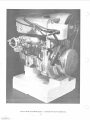
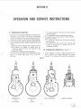
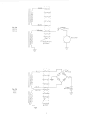
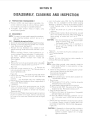
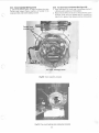
1.3 The model CCW340/400 engine is shown in Figure 1-1.
One illustration is used, since the two engines are similar in
external appearance. These engines are designed for use in
various snowmobile configurations and are suitable for use in
All Terrain Vehicles or similar applications.
c. The model 400 uses a smaller fan pulley than the 340
models and has an increased bore size to 65 mm. The piston
stroke is the same in both engines.
1.4 The instructions detail the procedures and tools requi red to ensure efficient operation, servicing and repair of
the engine and component parts. Refer to Parts Catalogue fo r
tool cross-reference.
Engine nuts, bolts and threads are metric except for the
engine mounting bolts, which are 7/ 16." SAE coarse, and the
power take off (P.T.O .) end of the crankshaft which is 1/2"
SAE fine (20TPI).
1.8 TECHNICAL DATA
Table 1-1 details specifications applicable to the models
CCW 340 and CCW 400 engines.
1.5 Carburetion data for the engine models covered in this
manual is detailed under separate instructions. For carburetor technical requirements refer to Appendix I, or to
appl icable manufacturer's specifications.
·
1.9 TOOL REQUIREMENT
The following is a list of tools required for the overhaul and
adjustment of models CCW 340 and CCW 400 engines:
1.6 MODEL DESIGNATION
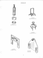
a. Special Tools
1.7 The letters and numbers in the subject engine models
designate the following:-
ccw
340/400
Manufacturer's type designation.
Cubic centimeter displacement
- S Manual Start
- E Electric Starter
- G Geared flywheel (for subsequent electric
starter installation.
SERIAL NOS.
COMMENCING
MODEL
YEAR
18
19
28
29
ccw 400
ccw 340
ccw 400
ccw 340
1969
Reference
Tool, Flywheel pu ller Part 43-0790-90
Para. 3.2. 1 ( 1)
Tool, Main Spring, Starter Rewind. 43-0797-60
Para. 4.4
Tool, Bearing puller (crankshaft). Part43-0791-70Para. 4.8.1
Tool, Flywheel Locking. Part 43-0798-40
Para. 3.2.1(j)
Para. 4.2.1 (a)
Tool, Fan Pulley Locking. 43-0792-50
b. Standard Tools
10/13 mm spanner
13/21 mm Box spanner and handle
22 mm spanner
22 mm socket wrench and ratchet
Piston ring removal tool
Piston ring compressor
Piston ring groove cleaning tool
Circl ip removal tool
Torque wrench (pounds feet)
Dial indicator
Degree wheel
1969
1970
1970
1-1
Feeler Gauge
Spark plug tap
Spark plug wire gauge
Thread Cl eaning tools
Wire brush (spark plugs)
Soft metal (non ferrous)
scraper
Phillips screw driver set
Common screw drivers
Soft hammer
Fig. 1-1 Model KEC 340/400 Engine - Left Side View from Flywheel end.
·•
1-2
CCWTOOL LIST
c
43-0797-60
REWIND SPRING TOOL
43-0791-70
BEARING PULLER
c
43-0790-90
FLYWHEEL PULLER
43-0798-40
FLYWH EEL LOCK
c
43-0792-50
FAN LOCK
1-3
TABLE 1-1
SPECIFICATION
Cycle:
Number of cylinders:
Capacity:
Stroke:
Bore:
Compression ratio:
Rating:
Maximum torque:
Specific fuel consumption
under full load:
Ignition system:
Contact breaker gap:
Ignition timing setting
when fully advanced :
(Static timing setting): BTDC
Spark Plug:
Spark plug gap:
Starter system:
Carburetor:
Fuel:
Mixture ratio :
Rotation direction of engine:
Weight:
Inlet port, timing
height
width
Exhaust port, timing
height
width
Piston height:
Piston ring, chromium plate, top
Piston ring, gray cast-iron, bottom
Cylinder head, volume
Cooling fan, blades
ratio
Magneto, make 340S only
340 GE
IGNITION COILS (340S)
Resistance, primary
Resistance, secondary
Current rating
Spark in free ai r
(three needle gap)
SECTION I
TECHNICAL DATA -1970 MODELS
ccw 340
ccw 400
Two stroke
Two
339 cc (20.9 cu. in.)
60 mm (2.36 in.)
60 mm (2.36 in.)
g_5
25 BHP at 5goo rpm
(23 lbs. ft.) at 5250 rpm
Two stroke
Two
39g cc (24.3 cu. in.)
60 mm (2.36 in.)
65 mm (2.56 in.)
g.5
30 BHP 5g00 rpm
(27.3 lbs. ft.) at 5500 rpm
400 gr/ps.h (O_gglb/ps.h)
Auto-advanced flywheel ignition
with lighting coii12V -75W
0.3 to 0.4 mm (.0 12 to .016 in.)
400 gr/ps.h (o.gglb/ps.h)
Auto-advanced flywheel ign it ion
with lighting coii12V- 75W
0.3 to 0.4 mm (.012 to .016 in.)
230 BTDC
go (.015" BTDC on Piston)
NGK B gH or equivalent
0.5 to 0.6 mm (0.020 to 0.024 in.)
Rewind starter with emergency
starting pulley or electric starter
(output 0.5 kw)
Tillotson HR or equivalent
Mixture, gasoline of known brand
and special air cooled two stroke
engine oil. (See Table 2-2)
20:1 (at normal operating conditions)
Left hand (standard configuration)
see toward the power take off end
of the engine.
60 lbs.
13go
23mm
42mm
16g 0
23mm
2gmm
67mm
230 BTDC
go (.015" BTDC on Piston)
NGK B gH or equivalent
0.51o 0.5 M.M. (0.020 to 0.024 in.)
Rewind starter with emergency
starting pulley or electric starter
(output 0.5 kw)
Tillotson HR or equivalent
Mixture, gasoline of known brand
and special air cooled two stroke
engine oil. (See Tab le 2-2)
20:1 (at normal operating conditions)
Left hand (standard configuration)
see toward the power take off end
of the engine.
60 lbs.
13go
23mm
46mm
16go
23mm
3gmm
67mm
1
1
17 cc
1
1
16.35 cc
g
._j>Jit)
1.g1:1
J/
Sawafuji V'
'""~ e e
Kokusan
Sawafuji
.4 ohms
g,500 ohms
1.75/2.25 amps
g mm @500 RPM
15 mm@ 5,500 RPM
1-4
g
1.g1 : 1
Kokusan
Kokusan
Kokusan
1.4 ohms
5,500 ohms
1.5/1.75 amps
9 mm @500 RPM
16 mm@ 5,500 RPM
J
SECTION
n
c
OPERATION AND SERVICE INSTRUCTIONS
1. To induce a mixture of fuel and air into the crankcase
via the carburetor.
2. To compress the charge in the combustion chamber.
d. The second stroke of the piston, from T.D.C. to B.D.C.,
also has two functions:
1. To uncover the exhaust ports and allow the burned
gases to escape.
2. To compress the fuel mixture in the crankcase and
transfer it through the two transfer ducts to the
combustion chamber.
2.1 PRINCIPLES OF OPERATION
c
c
a. The CCW two stroke engine is designed to complete in one
revolution, or two strokes of the piston, the complete
cycle of (a) fuel/air induction, (b) compression of the fuel
mixture, (c) combustion, (d) exhaust of the burned gases.
b. The construction of the engine requires a sealed crankcase
and a cylinder having four carefully positioned ports as
follows:
1. Carburetor inlet for induction of the fuel/air mixture.
2. Two transfer ducts leading to transfer ports for
transferring the mixture from the crankcase to the
combustion chamber.
3. Exhaust port for exhausting the burned gases.
c. The first stroke of the piston, from bottom dead center
(B.D.C.) to the top dead center (T.D.C.), has two
functions:
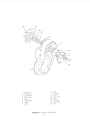
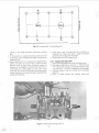
2.2 SEQUENCE OF OPERATION (see Figure 2-1)
a. As the crankshaft rotates, the piston moves from the
B.D .C. position, thus creating a depression (or partial
vacuum) in the crankcase. When the piston uncovers the
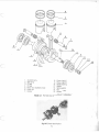
Fig. 2-1
1\1
COMPRESSION
AND
INDUCTANCE
COMBUSTION
OF
CHARGE
FUEL TRANSFER
2-1
LOOP SCAVENGE
b.
c.
d.
e.
carburetor inlet port, fuel/air mixture, metered by the
carburetor, is admitted to the crankcase.
Continued upward movement of the piston will compress
the charge in the combustion chamber until, at a point
near T.D.C., the spark from the spark plug will ignite the
mixture.
Resultant expansion of the ignited fuel will push the
piston toward· B.D.C. Moving downward, the piston first
uncovers the exhaust port and allows the hot gases, still
under considerable pressure, to escape to atmosphere
through the exhaust system.
Continuing downward, the piston will now uncover the
two transfer ports and close the carburetor inlet port. The
mixture in the crankcase and lower part of the cylinder is
displaced by the piston and conducted through the
transfer ducts to the combustion chamber above the
piston. The fresh charge, entering through the two
transfer ports will form a loop (see Figure 2-10), thus
scavenging the cylinder of burned gases.
The cycle will repeat continuously as from paragraph (a)
until the engine ignition is switched off.
2.3 IGNITION SYSTEM
2.3.1 General
The ignition system used with model CCW 340 and CCW 400
engines is basically the same as systems used with most
conventio nal two stroke engines. It consists of a low tension
magneto, two high tension ignition coils, two ignition spark
plugs, spark plug (high tension) lead wires, an ignition switch
and the required electrical wiring.
Modei340S engines differ from 340E, 340G, and 400 engines
in magneto design. Magnetos in use on the model 340S
incorporate only one low tension generating coil. All other
models covered in this manual use two low tension generating
coils. Refer to paragraphs 2.4.2.1 and 2.4.2.2.
sets are grounded to the magneto frame through a common
ground.
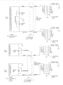
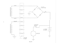
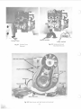
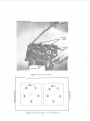
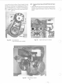
2.3.2.2 Kokusan Ignition (See Figure 2-3)
The magneto used with model 340E, 340G and 400
( KO KUSAN) ignition systems has two low tension generating
coils. One end of each coil is grounded to the magneto frame.
The other end of the coil connects in parallel to the breaker
point set and the primary of one ignition coil.
2.3.3 Operation (See Figures 2-2 and 2-3)
The ignition switch is connected in parallel with the primary
windings of the ignition coils. Operation of the ignition
switch to the "RUN" position, opens a circuit between the
windings and allows the contact breaker points to control the
ignition circuit.
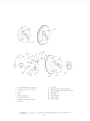
The flywheel incorporates four permanent magnets and a
breaker point cam and auto advance mechanism . In operation, as the flywheel rotates, an electrical current is generated
in the low tension generating coil. The rotating breaker point
cam activates the breaker points, opening and closing them in
accordance with a timed ignition sequence. (Refer to Section
V, paragraph 5.4.4). Closing the points causes the buildup of
a magnetic field in the ignition coils. Opening the points
causes a very rapid collapse of the field, thus inducing a high
voltage current in the secondary windings of the coil. High
tension spark plug wires conduct the high voltage current to
the spark plugs.
Self induced high voltage current in the primaries is momentarily stored in the condensers to prevent arcing across the
point contacts. When the contacts next close, the condensers
will discharge back to the ignition coils, thus assisting in the
buildup of the magnetic field in the coils.
The ignition circuit will continue to function until the
ignition switch is turned to the "0 FF" position which will
maintain a circuit and prevent ignition.
2.4 DETONATION:The internal combustion engine is designed to induce a
combustable mixture of gasoline and air into the cylinder
which is subsequently ignited by a spark plug, and the
resultant gas expansion utilized to produce the power stroke.
Some considerable care is taken in the design to ensure that
the combustion takes place at a controlled rate, but under
certain conditions the charge will burn at a highly excessivE)
rate, producing abnormal gas temperatures and pressures in
the cylinder. This condition is called detonation and may,
therefore, be defined as the rapid and uncontrolled burning
of the chargewh ich commences at the point of ignition by the
spark plug and is completed prematurely over a very short
movement of the piston.
2.3.2 Description
The magneto assembly is mounted to the engine crankcase at
the flywheel end. It functions to generate low tension
impulses in the primaries of the ignition coils. Two sets of
contact breaker points, one set for each cyl inder, are installed
in the magneto. 0 uring engine operation, a cam, mounted on
the flywheel, opens and closes the breaker points in sequence.
A condenser, wired in parallel across each set of breaker
points, protects the points from damage caused by selfinducted electrical surges in the primary coil. Lighting and
battery charging coils (see paragraph 2.5) are mounted on the
magneto coil plate. The coils produce the electrical power
required to operate a 12-volt lighting system and t o charge
the battery used with electric started engines.
Low tension (primary wires) leading from the magneto are
encased in a protective cover and routed through a grommet
located in the fan cover case, to the ignition coupler on the
fan cover.
2.4.1 The causes of detonation are many and varied, but all
have the common effect of overheating the charge towards
the spontaneous combustion temperature of the fuel. Consequently, when the charge is further heated by compression
and ignited by the spark, the flame spread rate is very rapid
indeed, resulting in the formation of the high pressure wave
which impinges on the combustion chamber surfaces to
create the sound of detonation of "pinging" which is so
familiar to many people.
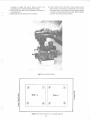
2.3.2.1 Sawafuji Ignition (See Figure 2-2)
The magneto used with model 340S (SAWAFUJI) ignition
systems has one low tension generating coil. Each end ofthe
coil is connected in parallel to the primary of one ignition coil
and one breaker point set. The condensers and breaker point
2.4.2 It cannot be emphasized too strongly that if detonation is allowed to persist, serious damage may result to the
2-2
J
-I
c
POINT
SEr
L.T.
COIL
TO
1-IGNITION
-SWITCH
1
IGNITION
COIL
POINT
SEr
K~
WHITE
WHITE
Fig. 2·2
SAWAFUJI MAGNETO
340S ONLy
L~
6or8 POLE
GNITION
COIL
c
K~
L.T.
COIL
POINT
. SEI'
,--,
CONDENSER
,,
I
IGNITION
COIL
I
_.1'0
IGNITION
1-sWITCH ·; - -
K~
~
0:::
~
H
L.T.
COIL
c
POINT
SET
0:::
P...o
ONDENSEf
I
I)
.,..
/
Fig. 2·3
KOKUSAN MAGNETO
340G-E
400 S-G-E
I
WHITE
~ER~2-3
6or8 POLE
IGNITION
COIL
blue in colour. Both of these wires are routed to the
ignition coupler.
The lighting coil winding is yellow in colour. One end is
routed to the ignition coupler and the other is grounded at
the magneto.
engine. Overheating of the engine can cause distortion of the
cylinder and cylinder head, seizing and burning of pistons,
breaking of cylinder flanges and studs etc.,
In addition, prolonged detonation may lead into pre-ignition
of the charge and even more serious consequences to the
engine. It is essential, therefore, that detonation should be
recognized and the cause eliminated as soon as possib1e.
A headlamp and tail lamp with maximum rating of 35
watts may be installed on the vehicle. The wire to operate
the light switch is connected to the yellow terminal in the
ignition coupler.
2.4.3 Most of the common causes of detonation can be
easily rectified: 1. High compression pressures. (CCW 340/400 = 175-180
PSI. cold at 500 RPM .)
2. Incandescent points in the combustion chamber due to
ash deposits.
3. Wrong type of spark plugs. (See Table 1-1)
4. Spark plug overheated due to seat washer being worn or
missing.
5. Incorrect ignition timing. (See section 5.4.4)
6. Weak carburetor settings.
7. High ambient temperatures. (Over 950 F.)
8. Partially choked exhaust system causing high back pressure.
MANUAL STARTED ENGINES (See Figure 2-6)Twin head
and tail lamps ( 12 V. 35 W- 12 V. 3 W).
See drawing Number E 340S-150. Two 12 volt, 35 watt
head lamps are connected in series with the single yellow wjre.
Three 12 volt, 3 watt tail (or speedometer) lights complete
the circuit in a series parallel connection with a ballast resistor
rated 7 ohms, 40 watts. A parallel circuit with a single pole
double throw switch is shown connected across the headlamps. In the event of a lamp failure, the switch can be placed
in left or right position to provide a circuit to the remaining
head and tail lamps.
N.B.-This circuit can be omitted if not required.
Materials required:-Load resister 7 ohms, 40 watts
SPOT Switch, 5 amps.
1
These items are available from Canadian Curtiss-Wright,
Limited.
2.4.4 PRE-IGNITION may be defined as the premature
burning of the charge due to spontaneous combustion, and
before the specified timed ignition point by the spark plug.
The resultant gas expansion, acting on the rising piston, generates extreme temperatures and pressures in the combustion
chamber and frequently results in broken pistons, bent
connecting rods, twisted or bent crankshaft and damaged
bearings.
Pre-ignition is usually caused by overheating and can be
readily identified by the very heavy knocking which is due to
gas expansion on the rising piston. It is usually preceded by
detonation, but certain conditions such as an under-sized or
choked exhaust system, will cause the engine to go straight
into pre-ignition without detonation. It is imperative that the
engine should be stopped at once by closing off the air supply
to the carburetor. It will be apparent that the engine cannot
be stopped by switching off the ignition.
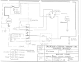
ELECTRIC STARTED ENGINES. (See Figure2-5)
b. On engines equipped with an electric starter, the two blue
wires at the ignition coupler are plugged into a C.C.W.
rectifier, part number 43-071 0-00,· and the AC is converted to DC (direct current). The black wire is grounded.
From the rectifier, DC is routed through a 7.5 ampere fuse
to the battery. Power to operate the lights is taken from
the battery.
2.5.2.2 Engines with Serial Numbers Modei340-G-F
2903614, Modei400-S-G-E 2809570 and Subsequent
a. Engines bearing serial numbers as above are equipped with
a six pole term inal coupling for the ignition and lighting
circuits. In addition, the separate lighting and battery
charging coils as per paragraph 2.5.2.1 have been changed
to a single center tapped coil. The ends have been
terminated in two yellow wires and the internally center
tapped ground connection has been extended by abrown
wire to the terminal block.·
2.5 LIGHTING SYSTEM
2.5.1 Vehicle lighting is provided by lighting and battery
charging coils in the magneto, and the necessary wiring and
light switches required to operate the system.
2.5.2 Operation
N.B.
2.5.2.1 Engines Previous to Serial Numbers:Model 340-2903614, Model 400-2809570. Typical vehicle
lighting circuit, See Figure 2-11.
Engines bearing serial numbers previous to 340-2903614 or
400-2809570 are equipped with an eight terminal ignition
coupler. The lighting and battery charging circuits include
two separate coil windings which produce 75 watts AC
(alternating current) during magneto operation. 0 ne coil
winding supplies the power required to operate the lighting
system and the other winding supplies the power required to
charge a 12 volt battery for use with electric started engines.
This brown wire may be disconnected provided a satisfactory
ground is maintained between the lighting circuits and the
engine.
The coil is rated at a nominal 12 volt 75 watt maximum and
can be connected to meet the various electrical configura·
tions.
1. ONE HEAD LAMP 12 V 35W- ONE TAIL LAMP 12V3W
See Figure 2-7
A ballast resistor rated at 5.3 ohms 40 watts must be
connected in parallel with the head lamp to prevent lamp burn
out. It will be noted from Figure 2-7 that an alternative
resistor at 7 ohms 40 watts will raise the operating voltage
across the lamp to give a better light at the cost of reduced
lamp life.
MANUAL STARTED ENGINES(SeeFigu re2-4)Singlehead
and tail lamp ( 12 V. 35 W-12 V. 3 W)
a. The two wires from the battery charging coil winding are
2-4
0
I
I
~
c
I
I
~
I
.I
~
I
I
Fig. 2-4
340 S-G
400 S-G
I
-<iTI_ _ _...:Jlf
-+C><}+-
~
~ _j
COU P LER
8 POLE
c
c.c.w
Rfc.i !F €R
I'
I
I
-r<><>T
I
I
I
~I
I
1
~
11 \JOLT -
B\.VE.
Fig. 2-5
340 E
400 E
~ A iT !:~'(-=-
I
~
r
-
_j
c.oul'l..ER
c
8 POLe'
2-5
_I_
I
I
I
A
I
c.c.w.
RECTIFIER
~
I
I
I
I
I
I
~
BLUE
N
m
I
Y.t:jLLVW
I
I
I~
I
I
-4xnI
I
---Yxr-L
I
l
1
I
I
~
~I
12 VOLT
BATTERY
I
)HEADLA~
l
COUPLER
8 POLE
u
Figure 2-6
G
u
2. Two Headlamps 12V35W - Two Tail Lamps 12V3W
(See Figure 2-8)
The head and tail lamps are connected in parallel across one
yellow wire and ground through the lighting switch, and the
ballast resistor is, of course, unnecessary.
intervals as necessary. (See Section Ill , para. 3.3.4). Discard
ex cessively burnt or damaged plugs. Install only specified
spark pi ugs after adjusting t o proper gap. (Table 1-1) .
2.6.2 Fan Belt
Periodically check fan belt for wear, fraying and proper
tension. A properly adjusted fan bel t should leave appro ximately 1/4 inch side play when flexed by hand at a point near
center of belt length.
Adjust fan belt tension as follows:
a. R-emove 19 mm nut, lockwasher and plain washer from
threaded end of fan shaft, using locking tool Part No.
43-0792-50.
b. Remove outer pulley. Remove spacer(s), as required, to
achieve pro per tension.
c. Install outer pu lley, plain washer, lockwasher and nut.
Ensure belt is properly engaged between pul ley halves.
Tighten nut securely.
NOTE: Retain su rp lus spacer( s) for use when a new belt is to
be installed.
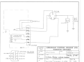
3. Electrical Start Engines (See Figure 2-9)
On engines equipped with an electric starter motor, a full
wave rectifier, CCW Part No. 43-0715-10, is connected to the
two yellow wires at the terminal coup ler and the A. C. output
is converted to D.C. 7.5 amp fuse is connected to the D.C.
output red wire and the circuit is completed via the lighting
switch to charge the battery. Head and tail lamps are
connected across t he battery term inals as shown in Figu re
2-9.
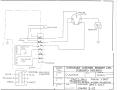
2.5.2.3 Model 340S only. Engines with serial numbers
2903614 & subsequent. See fig. 2-12.
Engines bearing serial numbers as above are equipped with
Sawafuji magnetos & six pole connectors for lighting &
ignition circuits. The separate lighting and battery charg ing
coil, have been retained as per paragraph 2.5.2.1.
2.6.3 Troubleshooting
Table 2-1 lists probable causes of engine malfunction and
remedial action required to co rrect faul ts. For spark plug,
breaker points and engine timi ng specificatio ns, refer to
T echnicall nformation, Table 1-1.
2.6 PERIODICSERVICING
2.6.1 Spark Plugs
Remove, inspect, clean and/or adjust spark plugs at regular
c
c
2-7
-t:
. ·..;..-
·'-'+
r
!-!-!
-
+
..
,.
' 1
MAD!: IN
~A
2-8
10 x 10 TO THE V2 INCH
GS-12
•
I
c
--p
·- - ~ ~~,·
.: :
' ....i
c
'.
'
c
(§ MICRO(GRAPH
MADE IN CANADA
2-9
10 x 10 TO THE V2 INCH
GS - 12
."
l i-
:r
:!: ~·
')
H.' ·-
4-
4 ··
.:..
_,_
:}_·=== '+..
-..1.
MADE IN CANADA
2-10
10 x tO TO THE V2 INCH
G8-12
(
-,
}
TO
(
I
PO I NTS
'
r
TO
ICrN IT ION
(O\L5
I
I
HF.."PLE\MP
CHJ\'K61Nu
(0\L
~
__:c
li6HTit-JGC OIL
____f_N G \l'lL
·· (OU PLE.R
2 RED
J
COUPlE p,
TOLERANCES
EXCEPT AS
V/£W FRO!'\. RtCOI\...
ST~Rii:R
£NO
NOTED
.
DECIMAL
FRACTIONAL
...
ANGULAR
...
..___ RU
TRANSTEX 11 S00-11-87
CANADIAN CURTISS- WRIGHT LTD.
TORONTO ONTARIO
DRAWN BY
SCALE
c.cw. ENGIN t:
TITLE
TYPICAL
DATE
I
Nov. a. 1~10 I
8
I
I
APPROVED BY
f'J\1\NUAL s T~RT
POLe WI~ING DI~G-RAl"\
DRAWING NUMBER
3 + O $ . G-.
FIGURE 2-10
4 00
S . G-.
\
~---
,
I
&W I TI..H
I
I
'TO
Ia
POINTS
luNI'tiON
C.OI\.';)
- - -- _l
HEj:o.t>LP..MP
1';0
(HAR<JING-
N
,- -
C.OIL
1~-,
-
..---:...----"!
- -
-
-
-
-,
I
I
I
I
I
-=-t2VOLT
FU~E
l\GHTIN<1
_
I
E~E
(DUPLER Vl~'W rr~o~
V/HITE-
I
2 RED
BLUE
3
4
"it-
REC..tl\l
ST/'.RHR t:NI.l
4-3·0710·00
TOLERANCES
EXCEPT AS
NOTED
FRACTIONAL
6 B LUE
8WHITE
CANADIAN CURTISS- WRIGHT LTD.
TORONTO ONTARIO
DECIMAL
-4-
YEUO'v/5
+
SCALE
C.C.'v/.
E~GlN£
TITLE
PI CAL
ANGULAR
....
DATE
Nov. 2 . 1'\IO
ftll
TDA"-JCl""'""a'V
til
-.:nn_a _ A.,
l
C . C w. R. 10 t T I F E R
~COUPLER
_..tt(
-=-.BATTERY
, ___ _ _ _ _ _ _ _ _ j
C.O I L
I
8
DRAWN BY
APPROVED BY
ELECTR\t START
POLE WIRINfr DIAGRAM
DRAWING NUMBER
flGURE 2-J J
3 4-0 E. .
4-00£.
•
l
-I
To I GN Iii ON COILS
~--------r-----
HFADI.N"\P
I
IO
~r
POINTS
w
l\Gt-\TINGCOIL
-
CHARGING
COIL
L
_f_/'fG IN E __
YF LLOW
~
R£D5
I r--l
F
J
r-cov?Lt:R
!COUPLER VIEW FACING
""--,_2 BL U£
CARBURETOR
.a
BLUE /-+<>i
I
4
TOLERANCES
EXCEPT AS
NOTED
CANADIAN CURTISS- WRIGHT LTD.
TORONTO ONTARIO
DECIMAL
+
C.t.W. ENGINE"
FRACTIONAL
6 WHITE
...
APPROVED BY
MANUt\l START
+
ANGULAR
DRAWN BY
SCALE
DATE
Nov l (;,.l<no
DRAWING NUMBER
I FIG-URE
3 +0
2-12
s.
0 N l '(
A
--1
TO IGNliiON
C0\1.~
TO
~T -1
POINT5
-
~
I
I
LIG-HTIN~
ANO
C HAAG-lNG COli...
I
CO\JPLEP.
__flilll N E - -
I
TOLERANCES
EXCEPT AS
NOTED
•
YE.LLOW /~
I -tCOUPLER
\J!EW FA(lNCl
CARBVP.HO 11
DECIMAL
RED 5
+
TYPJC~L
ANGULAR
)
TRANSTEX
Ill 1100-11-87
APPROVED
TITLE
DATE
6 POLE
I
+
RJI
DRAWN BY
SCALE
C.C.W. ENGINE
+
FRACTIONAL
3--~
CANADIAN CURTISS- WRIGHT LTD.
TORONTO ONTARIO
1\10 v 2. Iq10 I
BY
f"\1\NUAL START
WlRlWG- DtA6AAIW\
DRAWING NUMBER
3'40 G-.
F \G- uR E 2 - l 2. A
4 ( -""' s. G-.
)
; ----------------------~
----
-l
,--------
II
I
I
L----------1
TO IC.NI'l'ION C.OI\.'il
HEAD LAM~
':l-1
TO
~OINTS
en
I
LIGHTI~G AND
CtH~P.()INCJ C..OIL
,- - - - - - - - - -- -,
I
f•~ I
~
~I
I
I
l
I
____f}J G-1 ti
~--
COUPLER
. ___j
VIEW EAC~
YELLOVJJ~
C.~RBUBETOB
114-3 · 07iS·IO
TOLERANCES
EXCEPT AS
NOTED
5----+<:::::>~
TRANSTEX
Ill 1100-11-87
CANADIAN CURTISS - WRIGHT LTD.
TORONTO ONTARIO
DECIMAL
1-FRACTIONAL
3--+C>I
NJ
BATTER'<
'-( ---------C.W. R EC TIFE R
I
RED
1'-VC\.T
SCALE
C.C.W. EN&l~E
TITLE
+
T'<P\C.Al
ANGULAR
...
DATE
N~"· 2. 1~10
DRAWN BY
APPROVED BY
ELEC.TR\C STI\RT
6 PoL£
WlRlNG- t:>\1\GRM"\
DRAWING NUMBER
FlGURE c-13
34-0E.
400E..
TABLE 2-1
TROUBLE SHOOTING CHART
Trouble
Probable Cause
Remedy
Manual starter
rope comes out but
pawls don't engage.
1. Lack of friction plate
return spring action.
2. Defective pawls.
1. Check friction plate returnspring.
Manual starter rope
doesn't return.
1. Recoil spring broken or bent
2. Pulley housing warped or bent
3. Starting pulley worn.
1. Replace spring.
2. Replace housing.
3. Replace pulley.
Electric starter
inoperative
1. Loose electrical connections.
2. Poor ground
3. Faulty battery or circuits.
4. Faulty electric starter
1. Retighten connections.
2. Secure ground connection.
3. Check, recharge or replace
battery.
4. Check starter solenoid.
Repair or replace.
5. Inspect starter motor for evidence
of moisture and broken or worn
brushes. Dry out as necessary.
Replace brushes as required.
6. Check starter switch. Replace
if required.
7. Check harness or connector for
broken wire. Repair or replace.
Hard to start
or won't start
1. Carburetor adjustments too
1. Adjust carburetor. Refer
to Manufacturer's Specifications.
lean (not allowing enough gas
to engine).
2. Inoperative diaphragm orflapper
valve.
3. Engine not being choked to start
4. Spark plugs improperly gapped,
dirty or broken.
5. Magneto breaker points improperly
gapped or dirty.
6. Head gasket blown or leaking
7. Empty gas tank or improper fuel
mixture.
8. Water in fuel system
9. Weak coil or condenser
10. Obstructed fuel system
11. Air leak in crankcase or inlet
system.
12. Primarywirebroken.
13. Engine not timed properly.
14. Secondary wire not connected
or spark plug protector not
installed properly.
Impossible to adjust
idle
1. Spark retarding mechanism not
working properly.
2. Pistons or rings worn.
3. Faulty carburetor
2-16
Replace spring as required.
2. Check for broken or bent
pawls. Replace pawls as
required.
2. Refer to Manufacturer's
Specifications.
3. Ensure choke is fully closed.
4. Remove plugs. Clean, adjust or
install new plugs.
5. Clean, adjust or replace points.
6. Replace gasket
7. Refill tank with specified
fuel/oil mixture (See Table 1-1).
8. Drain fuel from carburetor. Add
carburetor de-icer as required
to fuel.
9. Replace faulty coil or
condenser
10. Disconnect fuel lines-clear
obstruction. Flush system.
Connect fuel lines.
11 . Check crankcase pressure
Table 3-1.
12. Repair or replace primary
w1re.
13. Re-time engine to proper
specifications.
14. Secure secondary wire or
spark plug protector.
1. Repair retard mechanism
2. Replace as necessary.
3. Check carburetor, check valve.
Refer to Manufacturer's Specifications.
TABLE 2.1
c
Missing at low speed
or won't idle smoothly
or slowly
Missing at high speed
or intermittent spark.
Coughs, spits, slows
down, surges
c
TROUBLE SHOOTING CHART
1. Incorrect carburetor idle
adjustment.
2. Spark plugs improperly gapped
or dirty.
3. Head gasket blown or leaking
4. Loose or broken magnet o wires
5 Magneto breaker points
improperly gapped or dirty.
6 Weak coil or condenser
7. Improper fuel mixture
( 1) Too much oil
(2) Too little oil
8. Leaking crankshaft seal
1. Adjust idle - Refer to
Manufacturer's Specifications.
2. Clean, adjust or install
new plugs.
3. Replace gasket.
4. Repair or rep lace wires.
5. Adjust, clean or install
new points.
6. Replace coil or condenser
7. Refuel, using specified
fuel/oil mixture (See Table 1-1 ).
1. Spark plugs improperly gapped
or dirty
2. Loose or broken magneto wi res.
3. !Magneto breaker points improperly
gap ped or dirty.
4. Weak coli or condenser
5. Heat range of spark plug
mcorrect.
6. Leakmg head gasket.
7. Engine improperly timed .
1. Clean, adjust or install new
plugs.
2. Repair or replace wires.
3. Clean, adjust or install
new points.
4. Replace coi l or condenser
5. Instal l specified spark plugs.
1.1dleorhighspeedjets
too lean.
2. Leaking gasket flange.
3 Inlet control lever set
too low
4. Pulsalion line obstructed
5 Fuel pump not supplying enough
fuel due to:
( 1) Punciured diaphragm
(2) Inoperative i lapper valve.
6. Crankca::e not properly seal ed.
7. Idle or main carburetor nozzle
obstructed.
8. Fuel line obstructed.
9. Carburetor inlet needle and
seat obstructed .
10. Welch plug leaking.
Overheating
1. Carbu 1etor too lean
2 Carburetor too rich
3 lnconect t:ming
4. Too much carbon
5. Spark plug too hot
6 Air deflector not Installed
7. A1r leak in manifo ld
8. Crank case seal leaking
Vibrates excessively or
runs rough and smokes.
1. Idle or high speed carbureto r
ad justmenl too rich.
2. Choke not opening properly
(bent linkage).
2-17
8. Replace seal.
6. Replace head gasket.
7. Re-time engine.
1 to 5.
Adjust carburetor or fuel pump.
Refer to Manufactu rer's Specifications.
}'
6. Reseal crankcase.
7. Refer to Manufacturer's
Specifications.
8. Remove fuel line. Clear
obstruction. Replace line.
9. Refer to Manufacturer's
Specifications.
10. Refer to Manufacturer's
Specifications.
1. & 2. Adjust carburetor.
Refer to Manufacturer's
Specifications.
3. Retime engine to Specifications.
4. Rem ove cylinder heads. Clean
top of pistons and inside
compression chamber. Clean out
exhaust port.
5. Instal l specified spark plugs.
6. Install air deflector.
7. Tighten nuts or change gaskets.
8. Fit new seal.
1. to 5. Adjust carbureto r. Refer
to Manufacturer's Specifications.
TABLE 2.1
· ,, "
. ; TROUBLE SHOOTING CHART
J Inlet control lever too high
(carburetor floods) .
4. ldle~irbleed plugged.
5. Welc'h plug loose.
6. Muffler obstructed
7. Engine not secured tightly to
engine support.
8. Water in gas.
.·Won't start, kicks back
.. ,,.:~~ nd backfires. · • .
No acceleration, low top
R.P.M., hard to start
Good spark but engine
runs on one cylinder.
B. Add carburetor de-icer fluid
as required.
9. Dry out switch, using suitable
de-icer spray or heat.
1. Spark plug wires reversed
2. Flywheel key. missing or-sheared
3. Faulty condenser
1. Install wire co rrectly .
2.:- Replace key.
3. Replace condenser
4. lmpropertiming
5. Faulty breaker points
6. Unhooked spark retarding
mechanism-or spring broken
4. Re-time engine
5. Adjust or replace points.
6. Reconnect mechanism or replace
spr1ng .
1. Spark plugs improperly gapped
7. Crankcase leaking
1. Clean, adjust or install new
plugs.
2. Clean, ad just or install new
points.
3. Replace coli or condenser.
4. Repair or replace magneto wires.
5. Replace head gasket.
6. Refer to carburetor manufacturer
Specifications.
7. Instal l new seal .
1. Leaking cylinder head
1. Check head for warps, cracks.
2. Magneto wires broken inside
2 Repair or replace wires.
(coil ground broken).
3. Cracked cylinder wall
4. Defective spark plug.
3. Replace fau lty cylinder.
or dirty.
2. Magneto breaker points improperly
gapped or dirty.
3. Faulty coi I or condenser.
4. Loose or broken magneto wires.
5. Blown head gasket.
6. Inlet lever adjustment too low
Install new gasket and cylinder head
1. High speed needle settoo lean .
2. Dirt behind needle and seat.
3. High speed jet obstructed.
· 4. Inlet lever set too low.
5. Choke partly closed .
6. Silencer obstructed.
7. Fuel pump not supplying enough
fuel due to:
( 1) Punctured diaphragm
(2) Flapper valves distorted.
8. Fuel line obstructed.
9. Not enough oil in gas.
10. Breaker points improperly
. gapped or dirty.
11. Engine improperly timed.
Engine run~ b~~using
choke at high speed
6. Check and clea r muffler.
7. Tighten engine mounting bolts.
9. Water in the ignition switch.
5. Breaker points improperly gapped
6. Crankcase seal leaking.
No acceleration . Idles
well but dies down when
put to full throttle.
)
1. High speed needle set too lean .
2. Dirt behind needle and seat.
2-18
4. Clean. adjust or instal l
new plug
5. Re-adjust po ints.
6. 1nstallnewseal
1. to 7.
Adjust carburetor. Refer to
Manufacturer's Specifications
8. Remove fuel line. Clear
obstruction. Replace line.
9. Refuel. using specified
"
fuel/oi l mixture.
10. Adjust, clean or install new
points.
11. Re-time engine to specifications
1. & 2. Adjust carburetor.
Refer to Manufacturer's
Specifications.
J
c
c
TROUBLE SHOOTING CHART
TABLE 2.1
3. Fuel line obstructed
No power under heavy
load
4. Inoperat ive fuel pump
3. Remove line, clear obstruction,
replace line.
4. Refer to Manufacturer's Specifications
1. Magneto breaker points improperly
1. Clean, adjust or install new
gapped or dirty.
2. Ignition timing too far advanced
3. Magneto co il plate loose
points.
2. Adjust timing
3. Check magneto and secure coil
plate.
4. Refer to Manufacturer's
Specifications.
4. Fau lty ca rburetion
Cranks over extremely
easy on one or both
cylinders. Loss of
comp ression.
f:ng1ne won't crank
over. Unable to rotate
flywheel.
1. Scored piston due to:
1. Replace faulty piston.
( 1) Not enough oil in gas.
(2) Lack of cooling
2. Blown head gasket.
3. Loose spark plug
4. Head bo lts not tight enough
2. Replace head gasket.
3. Check plug for security.
4. Torque head bolts to proper
specifications.
1. Piston rusted to cy linder wall
2. Crankshaft seized to bearing
(main or ro d) .
3. Broken co nnecting rod.
4. Flywheel seized to coil plate.
5. Engine improperly assembled after
repa1r.
2.7 OPERATING INSTRU CTIONS
1. Remove piston and cylinder.
Replace defective parts.
2&3. Disassemble engine.
Replace defective parts.
4. Remove flywheel.
Replace defective parts.
5. Recheck re-assembly procedure.
NOTE : If the engine fails to start after repeated attempts,
refer to Trouble Shooting Chart, Tabl e 2-1.
2.7.1 Preparation For Operation:
Ensure that the fuel tank is filled with the co rrect mi xture of
recommended gasoline and special air-cooled two stroke
engine oil . See Table 1-1.
CAUTION: When fil ling or ~opping up the fuel tank, use a
fuel strainer to prevent possible contam ination
of engine and fuel system components.
2.7.2.2 Starting the engine using electric starter.
a. Adjust throttle lever to approximately one-h al f full open
position.
b. Cl ose. ca rburetor choke lever. When starting a warm engine
it may not be necessary to close the choke.
c. Engage t he applicable ignition switch. If engine does not
start within 5 seconds, disengage the ignition switch.
Adjust throttle lever as required; wait approximately 30
secondsand repeat the starting procedure.
d. After the engine has started, gradually open the choke
lever and close t he throttl e lever until the engine runs
smoothly at idling speed (1000-1200 rpm). When the
engine is running at normal operating temperature the
choke should remain in the fully open position.
NOTE : If the engine fails to start after repeated attempts,
refer toT rouble Shoot ing Chart, Table 2-1 .
2. 7.2 Starting
2.7.2.1 Sta rting the engine using recoil sta rter.
a. Adjust throttle lever to approx imately one-half fu ll open
position.
b. Close carburetor choke lever. When starting a warm eng ine
it may not be necessary to close the choke.
c. Switch the ign ition to the RUN position .
d. Pul l lightly on the handle of the ro pe unt il a click is heard
when the pu lley engaged with the flywheel and t hen pull
strong ly on the rope. Let the handle return quickly to the
original posit ion. Do not let go of the handle unti l the rope
has fully retracted.
e. If engine does not start, repeat step (d) and adjust throttle
lever as required until the engine starts.
f. After the engine has started, gradual ly open the choke
lever and close throttle lever until the engine runs
smoothly at idling speed (1000-1200 rpm). When the
engine is running at normal operating temperatu re the
choke shou ld remain in the fully open position.
2.7.3 Stopping the Engine
To stop the engine, close throttle; switch off th e ignit ion. Do
not stop engine by grounding the spark plugs or disconnecting spark plug wires.
2.8 LUBRICATION
Lubricati on chart, Table 2-2, detai ls periodic lubrication
requirements. Further periodic lubrication of these engines is
not required.
2-19
TABLE 2-2
LUBRICATION CHA·RT
Component
Periodicity
Type/Method
Access
Recoil Starter
Center hub.
Main spring.
Pawls.
0 nee yearly or
during overhaul
Grease, low temper·
ature, Lubriplate or
equivalent (by hand)
Remove recoil
starter cover.
Remove friction
plate. (See·
Section Ill,
Para. 3.2.1 d and
Section IV, para.
4-3).
Electric
Starter drive
shaft and
spring (if
installed).
Once yearly or
during overhaul
Grease, low temperature, Lubriplate or
equivalent (by hand)
Remove starter
(See Section Ill,
Para. 3.2.1g).
Contact Breaker
Points (oilfelt pads)
Once yearly or
during overhaul
1 or 2 drops good
quality light
machine oil (oil
can).
Remove recoil
starter and starter
pulley. (See
Section Ill, Para.
3.2.1 d and 3.2.1 h).
Lubricate through
breakerpoint access
hole.
Contact Breaker
Point Cam
Once yearly or
during overhaul
Grease, low temperture, Lubriplate or
equivalent. Lightly
coat governor
assembly and flywheel
collar (by hand)
Remove flywheel
(See Para. 3.2.1 j)
Remove snap-ring.
Lift out cam.
Replace cam and
snap ring. (See
Section IV, Para.
4.4).
The following is a list of recommended brands of two stroke
engine oil:
·
Esso Snowtrac
Veedol Snowmobile
Shell Two Cycle Snowmobile
Mercury 50 New Formula "Quicksilver"
"Bardahl" Snowmobile VBA
2-20
SECTION
c
DISASSEMBLY, CLEANING AND INSPECTION
J. Lock the flywheel using CCW Tool Part #43-0798-40
remove the nut, lockwasher and flat washer securing
flywheel to crankshaft. Remove the flywheel as follows:
1. Install flywheel puller to the three tapped holes in
flywheel.
2. Tighten the center bolt of puller to 40 pounds-feet
maximum .
3. Using a wooden mallet or block and hammer, tap each
side of the flywheel alternately while maintaining the
torque setting on center bolt until the flywheel is
removed.
CAUTION: 1. Do not over torque center bolt on flywheel
puller. Excessive torque may result in breaking the puller attachment bolts.
2. Do not hammer on end of crankshaft to
remove flywheel. Damage to the shaft or
bearings may result.
3.1 PREPARATION FOR DISASSEMBLY
a. Remove muffler and exhaust pipe as applicable. Disconnect electrical wiring and controls. Remove engine
mounting bolts; place engine on asuitable workbench.
b. Thoroughly clean exterior surfaces of engine, using
suitable cleaning solvent.
c
m
3.2 DISASSEMBLY
NOTE: To prevent loss and expedite reassembly procedures,
keep attaching hardware with each part as it is
removed.
3.2.1 Disassemble the engine as follows:
a. Disconnect spark plug wires at spark plugs. Remove plugs.
b. Remove the ten bolts securing cylinder cover to engtne
body. Remove cover. See Figure 3-1
c. Remove the four hold-down nuts, washers and lockwashers securing intake and exhaust manifolds to cylinders.
Remove manifolds. Remove intake manifold with carburetor attached. Remove carburetor if it requires servicing. Refer to applicable carburetor manufacturer's
specifications. Remove insulators from intake side.
Discard gaskets.
Figure 3-2.
d. Remove the four bolts securing recoil starter to fan cover.
Remove starter to expose starter cup and fan belt pulley.
Figure 3-3.
e. Disconnect coupler attached to fan cover. Remove two
bolts secu ring coil cover to fan cover. Remove cover to
expose high tension coils.
Figure 3-3.
f. Remove the two bolts and spacers securing high tension
coils to fan cover. Remove coils with spark plug wires
attached.
g. Remove the two hold-down nuts, two attaching bolts
and lockwashers securing electric starter to engine body (if
so equipped) . Remove starter.
Remove starter.
h. Remove the three bolts securing starter cup, fan belt
pulley and window plate (if installed) to flywheel. Pull
outward and up on pulley to remove from flywheel.
Remove fan belt.
1. Remove the two Phillips screws securing ignition terminal
coupler and bracket to fan cover, and four bolts securing
fan cover to fan cover case. Remove fan cover to expose
flywheel.
Figure 3-6.
k. Remove the four bolts seCL'ring fan covercase to crankcase. Remove covercase.
Figure 3-7.
I. Remove the two screws secunng stator assembly to
crankcase. Remove stator assembly.
Figure 3-8.
NOTE: Unless being serviced, stator assembly should be
stored inside flywheel to ensure retention of magnetic properties.
m. Remove the five hold-down nuts securing each cylinder
head to cyl inder. Remove cylinder heads.
Discard cylinder head gaskets.
Tool: 13 mm box spanner.
NOTE: Before proceeding any further check crankshaft for
bend and twist as follows :
1. Check for twist:
(a) Rotate eng ine to T.D.C . on No. 1 cylinder using a dial
indicator mounted on the cylinder.
(b) Install and zero a degree wheel on the crankshaft.
(c) Rotate crankshaft 1800. The piston on No. 2 cylinder
should be at T.D.C. Permissable tolerance is 20.
2. Check for bend on either end :
(a) Mount a dial indicator at the junction of the parallel
and tapered sections of the shaft.
(b) Zero the indicator. Rotate the crankshaft one full
turn. Permissable run out is 0.003 inch on one rotation.
n. Remove the four hold-down nuts securing each cylinder
to crankcase. Remove cylinders to expose piston and
connect ing rod assemblies. Discard cylinder base gaskets.
Figure 3-10.
CAUTION: If disassembly is discontinued after cylinder or
piston removal , ensure that crankcase is kept
covered to prevent ingress of dirt or foreign
objects to crankcase.
3-1
J
exhaust manifold
Cylinder Cover
Intake manifold
Fig. 3-2 Intake and Exhaust
Manifolds Removed
Fig. 3-1 Cylinder Cover
Removed
disconnect
J
Fig. 3-3 Recoil starter and high tension coils removed
3-2
Fig. 3-4 Starter cup and fan belt pul ley removed .
c
Fig. 3-5 Fan cover removed
3-3
)
Fig. 3-6
Removing flywheel
Fig. 3·7 Fan cover case removed
3·4
Fig. 3-6A
c
c
Stator a·ssembly
i ------
Fig. 3-8 Stator assemb ly removed
3-5
Fig. 3-9 Cylinder heads removed
Fig. 3-10
Cylinders removed
3-6
)
c
wear, cracks, and evidence of corrosion; attaching hardware and attachment holes for wear and condition of
threads. If it is necessary to dress the threads, use suitable
thread cleaning tools. Repair or replace damaged parts and
any parts that fail to meet appl icable specifications. Refer
to Section IV, Repair and Replacement.
b. Perform additional inspections as detailed in paragraphs
3.3.4 to 3.3.13.
o. Refer to Section IV, Figure 4-7
Before removing pistons (5), ensure that the piston crown
is marked with an arrow directed toward the exhaust port.
If no arrow is legible, inscribe the piston crown acco rdingly. Using a suitable circlip removal tool, remove one
of the two circlips (7) securing each piston pin (6) in
position. Use a propane torch or cloth soaked in hot water
and heat the pistons until warm to the touch ( 1200-1400
F). Use a soft drift to push the pins out from the opposite
side. Remove needle bearings ( 10) from connect ing rods
small end.
CAUTION : Exercise care when removing piston pins to
prevent damage to needle bearings. Keep bearings adequately protected until time of assembly. Figure3-11.
p. Remove piston rings from piston ring groove, using a
suitable ring removal tool .
q. Remove the ten bolts, plain washers and lockwashers
joining the two halves of crankcase. Separate crankcase by
pulling the two halves apart. Remove the crankshaft.
Remove the four seal retaining circlips from crankcase
lower half. (Refer to Sect ion V, figure 5-1).
CAUTION: Do not use a screw driver to pry the crankcase
apart. If necessa ry, use a soft hammer and tap the
case lightly on either end.
3.3.4 Spark Plugs Inspection and Adjustment
a. Inspect spark plugs for general condition, cracked or
broken insulators and burned electrodes.
Guide to spark plug serviceability:
1. Center electrode burned brown indicates plug is
functioning normally.
2. Center electrode burned white indicates the plug is too
low in thermal value. Discard plug and install new plug
of specified type.
3. Center electrode burned black indicates the plug is too
high in thermal value. Discard plug and install new plug
of specified type.
b. Adjust spark plug gap to 0.6 to 0.7 mm. (0.023 to 0.025)
in). Bend the outside (ground) electrode only. Use a spark
plug wire gauge to measure the gap. Discard plug if
electrode is burned ex~ssively or if specified gap cannot
be maintained.
c. Inspect spark ~lug wires fo r condition of insulation ;
rubber bushings for splitting or deteri oration ; tips for
security. Replace defective wires.
Figure 3-12
3.3 CLEANING ANO INSPECTION
c
3.3.1 Cleaning
Pri or to inspection clean all parts, except the magneto
assembly, by immersing and soaking in a suitable cleaning
solvent or using specified methods. Clean the crankshaft
before cleaning other components, to protect bearings from
possible damage due to dirty cleaning solvent. Thoroughly
dry all parts after cleaning.
Pay particular attention to the fo llowing special instructions:
a. Spark plugs:
Remove light carbon deposits by brushing lightly with a
wire brush. If plug is excessively dirty and proper clean ing
equipment is not available, install a new spark plug.
b. Piston ring grooves, piston crowns, cylinder heads:
Use the proper groove cleaning tool for cleaning piston
ring grooves. Normal clea ning methods should be sufficient for clean ing piston crowns and cylinder heads.
c. Spark plug holes and exhaust ports:
Carefully remove heavy carbon deposits from these areas,
using a soft metal (non-ferrous) scraper. Use a spark plug
tap to clean threads.
CAUTION: Do not scrape down to base metal su rfaces when
removing heavy carbon deposits. Exercise care
while cleaning spark plug holes, to prevent
damage to the threaded area.
d. Magneto:
Thoroughly dryclean the magneto using compressed air or
suitable cleaning materials. Ensure no moisture or oily
f ilm remains after clean ing.
3.3.5 Fan Covers
a. Inspect fins for cracks; fan for blade damage, freedom of
movement and evidence of binding . Dress out nicks or
dents. Replace fan if a blade is cracked or broken since the
balance will be affected.
b. Inspect fan belt for stretch, fraying and deterioration .
3.3.6 Recoil Starter
a. Pull starter rope out and permit it to recoil. Do not let rope
snap back on recoil. Rope should pull out smoothly and
recoil without hesitation. A weak or incomplete recoil
indicates a defective or maladjusted main spring.
b. Check for smooth operation of pawls. When the rope is
pulled out, pawls should move outward; when the rope
recoils, pawls should move inward.
c. Inspect handle and rope guide for general condition and
security of attachment.
3.3. 7 Electric Starter (if installed)
a. Inspect drive shaft and spring for condition, smooth
operation and security. Lubricate in accordance with
Lubrication Chart. Table 2-2. ·
NOTE: Disassembly or repair of electric starters shou ld be
performed by authorized dealers only. R~place
defective starters if overhaul facilities are not available.
3.3.8 Magneto Assembly
a. Inspect coil plate for damage and security.
b. Inspect low tension generation coil(s) and lighting coi ls
for general condition and security.
c. Inspect contact breaker points and condensers for condition; breaker points for wear, burning or pitting. Serviceable points appear a greyish frosty color. If points are in
3.3.2 Inspection
3.3.3 General
a. After disassembly, clean all parts in accordance with
paragraph 3.3.1. Inspect all parts for obvious damage,
3-7
)
Fig. 3-11 Removing pistons
()
Connecting rods
0
Fig. 3-12 Upper Crankcase half removed
3-8
2. If cyl inder has been rebored and hor)ed, replace
defective piston with oversize piston as listed in Table
3-1.
serviceable condition, the condenser can be considered
serviceable. Inspect oil felt pads for cond it ion and
security; lubricate in accordance with Lubrication Ch art,
Table 2-2.
d. Inspect all electrical connections for security; insulation
for chafing and deterioration.
3.3.12 Crankshaft and Connecting Rods
a. Inspect threads on each en d of shaft. The mating nut on
the flywheel end of the shaft should turn on all the way by
hand without excessive looseness.
Use a suitable thread cleaning tool to remove burrs from
the threads. Replace worn nuts.
b. Check tapered surface of flywheel end of shaft for scoring
and wear. When placed on the shaft hand t ight, the
flywheel should not wobble.
c. Inspect keyway and Woodruff key for damage and wear.
Replace worn keys.
d. Inspect ball bearings for wea r, free movement and
security.
e. Using Vee blocks (2) on a flat surface, support the
crankshaft on the center main bearings. Mount dial
indicators at junction of tapered and parallel sections of
the shaft and rotate crankshaft by the connecting rods.
Refer to Tab le 3-1 for tolerances.
f. Check crankshaft for bend or twist on the crankshaft
journals. Use a dial indicator placed on the main bearing
journals. Zero the indicator. Rotate crankshaft one full
turn. Refer to Table 3-1 for tolerances.
g. Check connecting rod diameter at small end; side and
vertical clearance at large end. Refer to Table 3-1 for
method of inspection and tolerance.
h. Check connecting rod twist as follows:
1. Insert a bar, 100 mm long or any other convenient
length, into the connecting rod small end . Centralize
the rod using a depth gauge and lock in position.
2. Support connecting rod horizontally. Using a dial
indicator measure the maximum height at opposite
ends of the bar when the rod is twisted to the right and
to the left. Any variation indicates connecting rod
twist. RefertoTable3-1 for tolerance.
1. Check connecting rod tilt as fo llows:
1. Repeatsteph(l).
2. Support connecting rod vertically. Using a dial test
indicator, measure the amou nt of movement at ends of
bar when bar is tilted to the right and to the left. The
difference between the two readings indicates the
amount of tilt. Refer to Tab le 3-1 for toleran ce.
3.3.9 Flywheel Assembly
a. Inspect cam, governor weight(s) and spring(s) for general
co nd iti on and security; cam for wear, particu Ia rly at point
of contact with governor weights.
b. Check flywheel taper for snug fitting. When placed on
crankshaft hand tight, the flywheel should not wobble.
c. Inspect magnets for nicks, scores or burrs. Use a suitab le
stone to smooth off high spots.
d. Inspect ring gear and teeth (if installed) for wear, general
condition and security.
e. Lubricate cam, governor weight and spring in accordance
with Lubrication Chart, Table 2-2.
c
3.3.1 0 Cylinder Heads and Cylinders
a. Inspect cylinder heads and cylinders for pitting, scoring
and evidence of corros ion.
b. Check cylinder heads for warp or distortion as follows:
1. Place cylinder head, flat side down, on a surface plate
or suitable measuring device.
2. Using a feeler gauge, measure amount of distort ion at
point of contact between cy linder head and surface
plate.
Take a reading at each of the five Iocat ions between
cylinder head hold down studs.
Maximum allowable distortion at any one location is
0.002 inch.
c. Check cylinders for distortion as follows:
1. Install a serviceable head on cylinder to be checked.
Do not install hold down nuts.
2. Using a feeler gauge, measure amount of distortion at
point of contact between cylinder head and cylinder.
Take a reading at each of the five locations between
cylinder head hold down studs.
Maximum allowable distortion at any one location is
0.002 inch.
d. Using a dial indicator or suitable measuring device, check
inside diameter of cylinders. Cylinders, worn beyond
standard tolerances, may be rebored to accomodate the
instal lation of oversize pistons. Refer to Table 3-1 for
standard and oversize fits and tolerances. The oversizes
listed in the table are the maximum allowable. Discard
cylinders that requ ire boring in excess of tol erance shown.
Replace with serviceab le cylinders.
3.3.13 Crankcase
a. Inspect crankcase mating surfaces for deep scratches,
scoring and pitting.
b. Inspect bearing and oi l sea l retaining inserts for wear,
scoring or conditions which could cause leaks.
c. Inspect at tach ing dowel pins for wear and security.
d. Discard crankcase if normal repair procedures are not
sufficient to correct defects.
NOTE: Rebored cylinders should be honed with a fine
finishing stone.
3.3.11 Pistons, Pins and Rings
a. Inspect pistons, pins and rings for scoring and wear; piston
crowns for pitting, evidence of corrosion and distortion.
b. Check diameter of pistons, pins and pin bore; piston ring
end and side clearances. Refer to Table 3-1 for method of
inspection and tolerances.
c. Discard any parts that fail to meet applicable specifications and note the following:
1. If cylinder has been inspected and found serviceab le,
replace defective piston with new standard size piston.
3.3.14 Fits and Tolerances
Table 3-1 lists standard fits and tolerances to be checked
during inspection of pistons, piston pins, cylinders and
crankshaft. It also lists allowab le oversizes of pistons and
rings. If suggested method of inspection is not availab le, use
suitable measuring devices.
3-9
j
CCW Model 340-400
TABLE 3-1 (FITS AND TOLERANCES)
Std. Size
Component
Cylinder
Connecting Rod, small end
big end
ln.
Mm
Tolerances
Inches
Minus
Plus
*2.36
#2.56
.867
60
65
22
N/A
1.261
'32
N/A
.00 1
.014
.016'
N/A
side clearance
vertical clearance
N/A
twist
bend
Crankshaft
permissable misalignment due
to bend or twist.
Crankshaft, end float
Piston, at
*2.36
#2.56
Piston Pin, c/1
Bottom of skirt
Piston Pin Bore
Piston Pin
Piston Ring, No.1
groove clearance
end clearance
.709
.709
.083
Piston Ring, No. 2
groove clearance
end clearance
.083
18
18
.0004
.0015
.003
.001
.0035
N/A
.003
N/A
.011
.012
.007
.008
.004
.0047
.0004
.0003
.0025
.004
.004
.012
.0014
.003
.004
.012
3-10
*Model 340
#400
Method of
Inspection
J
0 iall ndicator
Dial Indicator
N/A
N/A
N/A
60
65
Top land
.0007
N/A
0003
.0008
.0004
Remarks
Dial Indicator
Measured at ends of bar
3.94" centred in small
end (See Manual)
Dial Indicator
Measured at junction
of taper and parallel
sections (see manual) .
Dial Indicator
Feeler gauge.
*340
#400
Micrometer
N/A
N/A
N/A
N/A
N/A
N/A
N/A
N/A
)
Dial Indicator
Micrometer
Feeler Gauges
SECTION 1V
Q
REPAIR AND REPLACEMENT
4.1 GENERAL
4.3 RECOIL STARTER (See Figure 4-2)
4.1.1 The repair and replacement instructions detailed in
this sect ion are included to assist in the disassembly,
replacement of defect ive parts and- assembly of major
sub-assem blies. It is not necessary to completely disassemble
the sub-assem blies un less inspection procedures reveal
defects. Perfo rm only those steps necessary to gain access to
the defective part(s} and to effect the necessary repairs.
4.3.1 Disassembly
a. Untie the knot in the rope at rope handl e ( 15). Remove
handle and al low the rope to recoil slowly into the case
( 12). Unscrew and remove rope guide ( 13).
b. Remove retaining nut (2), lockwasher (3) and flatwasher
(4) from threaded shaft of reel hub ( 10).
c. Manipulate friction plate (5) on reel hub until eye end of
return spring (7) aligns with retaining slot (22) . Remove
friction plate.
d. Remove the three pawls (6).
e. Remove return spring (7), sp ring (8) and cup washer (9).
Note position of plain end of return spring in the spring
retaining ho le in reel hub.
f. Remove reel (10). Unwind the rope; lift and untie the
knotted end from center hub of reel.
g. Lift long ro lled end of main spring ( 11) from t he fixed
spring retaining pin in the case and carefully remove the
spring.
h. Clean all parts, except rope, using a su itable clean ing
solvent. If rope requires clean ing, wash it in a solution of
soap and water. Thoroughl y dry all parts after cleaning.
1. Inspect all parts for obvious damage and wear.
4.2 FAN COVER (Seefigure4-1)
4.2.1
c
Disassembly
a. Remove nut (2}, lockwasher (3}, and pla in washer (4}
from threaded end of fan shaft. Spacer (5) is permanently
secured to ou ter pulley (6).
Tool: 19 mm box spanner, Locking tool, Part No.
43-0792-50.
NOTE: Drill one 1/4" hole in pulley to take pin of locking
tool .
b. Remove outer half (6) of fan belt pulley, spacers (7, 8, 9)
inner half ( 10) of pulley, and spacer ( 11) from shaft.
c. Tap Iightly on end of fan shaft to remove fan ( 16) from fan
cover.
d. Inner bea ring (15) should rem ain on fan shaft assembly
and can be rem oved by sliding it off the shaft. To remove
outer bearing ( 12), turn the case over; use a su itable soft
drift to tap bearing out of retainer. Remove spacer ( 13}. It
is not necessary to remove snap ring ( 14) unless it is found
defective. Use suitable removal tool to remove snap ring.
e. Clean al l parts, except bearinqs, usinq suitable clean ing
solvent. Wipe bearings clean, using aclean cloth moistened
with cleaning solvent. Thoroughly dry al l parts after
cleaning.
c
4.3.2 Assembly
a. Replace defective parts.
b. Install main spring as follows:
1. Secure main spring winding tool, part number
43-0797-60, or equivalent tool, circul ar end up, in a
suitable bench vise.
2. Start with the long rolled end of main spring ( 11) and
wind spring into circular end of tool in a clockwise
direction.
3. Remove tool from vise. Grasp th e too l by its handle
and lower the tool , with spring installed, into case (1 2).
4. Secu re the long roll ed end of spring over the fixed
spring retaining pin. Remove winding too l. Apply a
light film of Lubriplate, or equ ivalent, to spring.
c. Secure case, open side up, in bench vise.
d. Tie a knot at one end of t he rope. Secure knotted end
around center hub of reel (10) . Pull rope taut and wind
entire rope around reel in an anti-cl ockwise direction
until the free end protrudes through the not ched section
of the reel.
e. Apply a light f ilm of Lubriplate, or equivalent, to center
hub of case and install the reel. Pu sh down and rotate
4.2.2 Assembly
a. Replace defective parts.
b. Install snap ring ( 14) if it has been removed .
c. Insta ll outer bearing (12). Turn case over; install spacer
( 13) and inner bearing ( 15). Ensure bearings are properly
seated with no evid ence of binding. If necessary, use asoft
steel drift to tap bearings into position. Ensure that no dirt
or foreign material enters bearings.
d. Reverse disassembly steps (a) to (c). Tighten reta ining nut
securely, using lock too l No. 43-0792-50.
e. Check fan for proper operation.
4-1
16
I~
D
9. Spacer
1. Fan cover
2. Retain ing nut
3. Lockwasher
4. Plain washer
5. Spacer
6. Outer pulley
7. Spacer
8. Spacer
FIGURE 4-1
10.
11.
12.
13.
14.
15.
16.
Inner pulley
Spacer
Outer bearing
Spacer
Snap ring
Inner bearing
Fan
FAN COVER ASSEMBLY .
4-2
/6
1.
2.
3.
4.
5.
6.
7.
8.
9.
10.
11.
Starter pulley
Retaining nut
Lockwasher
Flatwasher
Friction plate
Pawl (each 3)
Friction plate return spring
Spring
Cup washer
Reel
Main spring
12.
13.
14.
15.
16.
17.
Case
Ropeguide
Rope
Handle
End piece
Bolt, starter to fan cover
attaching
18. Lockwasher
19. Flatwasher
20. Bolt, starter pulley to flywheel attaching
21. Lac kwasher
22. Slot, return spring retaining
23. Hook, main spring retaining
G
FIGURE 4-2 RECOIL STARTER ASSEMBLY
4-3
D
2
1
8. Lug plate
9. Flywheel
1.
2.
3.
4.
I;
··<'
Flywheel assembly
Snap ring
Cam
Snap ring
5. Washer
6. Governor weight
7. Governor spring
10.
11.
12.
13.
14.
Screw, lug plate attaching
Spring washer
Washer
Screw, governor stop
Spring washer
)
FIGURE 4-3 FLYWHEEL ASSEMBLY- 340S
4-4
c
c
4.5 FLYWHEEL ASSEMBL Y-KOKUSAN-MODELS
340E, 340G and all400 MODELS (See Figure 4-4)
reel in an anti-clockwise direction until the hook (23)
engages with the free end of main spring. Tension will be
felt when reel and spring are properly engaged.
f. Rotate reel a maximum of three complete turns in an
ant i-c Iockwise direction. 0 o not exceed three turns; hold
reel in this position and feed free end of rope through case
at the rope guide hole. Install rope guide. Loosely knot
the rope to prevent recoil.
g. Apply a light film of Lubriplate or equivalent to pawls (6)
and install them on the reel in the pawl retainers.
h. Install cup washer (9) flat side down, spring (8) and
return spring (7) . Ensure that plain end of return spring is
properly engaged in the retaining hole in reel hub.
1. Install friction plate (5) over reel hub. Manipulate plate
until eye end of return spring engages and locks crosswise
in retaining slot (22).
J. Rotate friction plate until the three notches are aligned
with pawls when pawls are at the recoil position.
k. Install flatwasher (4) , lockwasher (3), and nut (2) .
Tighten nut securely.
I. Untie the temporary knot in free end of rope and install
the rope hand le. Tie a permanent knot and fit handle
securely.
m. Check starter for proper operation. When handle is pulled
outward, pawls should move outward.
4.5.1 Disassembly
NOTE: Complete disassembly of flywheel assemblies should
be performed by authorized dealers only . The
auto-advance mechanism is pre-set during manufacture and should require no further adjustment. If
inspection reveals faulty governor parts or defective
magnets, install a new flywheel assembly or return
flywheel to overhaul facility.
a. Remove snap ring (3) securing breaker po int cam (4) to
flywheel collar, using a suitable snap ring removal tool.
Lift cam off collar. Check cam and co llar for scoring and
wear; governor weight stops fo r wear and security.
Replace defective parts.
4.5.2 Assembly
a. Apply a light film of Lubriplate or equivalent to outer
surface of flywheel collar.
b. Reverse removal procedure.
c. Lubricate in accordance with Lubrication Chart, Table
2-2.
d. Check mechanism for proper operation.
NOTE: If main spring is to be installed without the use of a
spring winding tool, wind main spring into case in an
anti-clockwise direction. Clockwise installation on
the winding tool is necessary to ensure correct
anti-clockwise installation of the spring when tool is
placed upside down in the case.
4.6 STATOR ASSEMBL Y-SAWAFUJI - MODEL 340S
(See Figure 4-5)
NOTE: Complete disassembly of stato r assemblies should be
performed by authorized dealers only. Normal disassemb ly should be restricted to removal and replacement of defective contact breaker point sets, oil felt
pads or condensers. If inspection reveals additional
maintenance requirements, install a new assembly or
return stator to overhaul facility.
4.4 FLYWHEEL ASSEMBL Y-SAWAFUJI-MODEL340S
(See Fig. 4-3)
4.6.1 Contact Breaker Point sets
4.4.1 Disassembly
NOTE: Complete disassembly of flywheel assemb lies shou ld
be performed by authorized dealers only. The auto
advance mechanism is pre-set during manufacture
and should require no further adjustment. If inspection reveals faulty governor parts or defective magnets, install a new flywheel assembly or return
f lywheel to overhaul facility.
a. Remove snap ring (2) securing breaker point cam (3) to
flywheel collar, using a suitable snap ring removal tool.
Lift cam off co llar. Check cam and collar for scoring and
wear; governor weight stop screw ( 10) for wear and
secu rity. Replace defective parts.
--·-
NOTE: Removal and installation procedure is appl icable to
both point sets.
4.6.1.1 Removal
a. Loosen electrical terminal connecto r (28) securing condensor primary wire at co ntact breaker point set (7) .
0 isconnect primary wire.
b. Remove retaining screw ( 18), lockwasher (16) an d washer
( 17) securing contact breaker po ints to coil plate (2).
Remove breaker point set.
4.6.1.2 Installation
a. Apply a light film of Lubriplate or equ ivalent to pivot
shaft.
b. Reverse removal procedure.
4.4.2 Assembly
a. Apply a light film of Lubriplate or equivalent to outer
surface of flywheel collar.
b. Reverse removal procedure.
c. Lubricate in accordance with Lubrication Chart, Table
2-2.
d. Check mechanism for proper operation.
CAUTION: Ensure no lubricant gets on breaker points
during installation. Contaminated points will
burn during engine operation.
c. Adjust points to specified gap. Refer to Section V,
Paragraph 5.4.3.
4-5
1. Flywheel assembly with ring gear
2. Flywheel assembly, less ring gear
9. Flywheel
10. Ring, governor weight attach ing
11 . Screw, lug plate to flywheel attaching
3. Snap ring
4. Cam
12.
13.
14.
15.
16.
5. Washer
6. Governor Spring (2)
7. Governor weight (2)
8. Lug, spring to governor weight
attaching
Spring washer
Ringgear
Bolt, ring gear
Spring washer
Window plate
FIGURE 4-4 FLYWHEEL ASS EMBLY (KOKUSAN MAGNETO) 340E, 340G, 400
4-6
26
27
-~~ ,~-!
14
c
~ ~~12
fi ll @~
25
24
-I
2
22
28
C-
1.
2.
3.
4.
5.
6.
7.
8.
9.
Stator assembly
Coil Plate
Primary Ign ition Coil
Lighting co il
Condenser (White)
Condenser (Red)
Po int Set
Oilfelt & Holder
Protector
10. Coupler
11. Washer
12. Screw
13. Spring washer
14. Washer
15. Screw
16. Spring washer
17. Washer
18. Screw
19.
20.
21.
22.
23.
24.
25.
26.
27.
28.
Screw
Spring Washer
Screw
Washer
E Ri ng
Bracket, Coupler
Rubber Bushing
Spade Connector
Spade Connector
Terminal Connector
,-..
FIG. 4-5
STATOR ASSEMBLY (SAWAFUJI IGNITION)
4-7
~--/";4
12
l! ,~r-13
!'---,
29
1
31
-l ,
7
1. Stator Assembly
.
2 Coil Plate. Generating Coil
3. Low Tens10~
·
· Coil
4. Lighting (Red)
Condenser
. )
5. Con denser (White
6.
7 PointSet
8. Oil. FeIt & Holder
9· Protector
1 Coupler
o:
11 _
12.
13.
14_
15
16.·
17_
18.
19_
2o_
Washer
Screw
Spring Washer
Washer
Screw
· g Washer
Sprm
Washer
Screw
Screw
Screw
FIG. 4-6 (KO KUSAN IGNITION)
4-8
21.
2
2.
23.
24.
25.
26.
27
.
28.
29.
30.
31 .
32.
Screw
r
.
Spri ng Wa~~~ Coil Attaching
Bolt, lgnitPiate Attaching
Bolt, Coil
W~sher
Primary Ignition Coil
Clamp
d Connector
Spa/ Connector
Spa ~ t Coup ler
Brae : r·Bushing
Rubb I Connector
Termma
)
c
c
1.
2.
3.
4.
5.
6.
7.
Crankshaft ass'y
Ball bearing
Oil seal
Oil seal
Piston (note inscribed arrow)
Piston pin
Circlip
8.
9.
10.
11 .
12.
13.
14.
Piston ring# 1
Piston ring# 2
Needle bearing
Washer
Spring washer
Nut
Woodruff key
FIGURE 4-7 PI STON AND CRANKSHAFT ASSEMBLY
Fig. 4-8 Oil seals identification
4-9
4.6.2 Condensers and Oil Felt Pads
NOTE: Removal and installation procedure is applicable to
both condensers.
b. Remove retaining screw (15) or (19) as applicable, and
washer (16) securing condenser to coil plate (2) . Remove
condenser and oil felt pad (if attached). Check pad for
condition and replace if lubricating capacity is questionable.
4.6.2.1 Removal
a. Loosen electrical terminal connector (28) and disconnect
primary wire at contact breaker point set (7) .
b. Unsolder condenser wires at terminal on low tension
generation co il (3) and at connector on eng ine body. .
c. Remove retaining screw (15) and washer (16) secunng
condenser an d oil felt pad (8) to co il plate (2). Remove
condenser and oil felt pad . Check pad for condition and
replace if lubricating capacity is questionable.
4. 7.2.2 Installation
a. Reverse removal procedure.
b. Lubricate oil felt pad . Refer to Lubrication Chart, Table
2-2.
4.8 CRANKSHAFT (See Figure 4-7)
NOTE: If inspection revea ls maintenance requirements beyond outer ball bearing or outer oil seal remova l and
installation, install a new crankshaft.
4.6.2.2 Installation
a. Reverse removal procedure. Resolder condenser wires at
primary coi l and ignition coupler.
.
b. Secure condense r primary wire to contact breaker po1nt
set at term inal connecto r (28).
c. Lubricate oi l felt pad. Refer to Lubrication Chart, Table
2-2.
4.8.1 Oil Seal and Outer Bearing
4.8.1.1 Removal
a. Remove Woodruff key (14) from tapered end of crankshaft assemb ly, using suitable pliers or removal tool.
b. Remove oi l seals (3) and (4) . Seals are a snug fit, and can
be removed by sliding them along the shaft. Discard seals.
c. Remove outer bearings (2), one from each en d of
crankshaft, using bearing puller or suitable removal tool.
4.7 STATOR ASSEMBL Y-KOKUSAN - MOOELS 340E,
340G, and ALL 400 MODELS. (See Figure 4-6)
NOTE: Complete disassembly of stator assembl ies should be
performed by authorized dealers only. Normal disassemb ly should be restricted to removal and replacement of contact breaker po int sets, oil felt pads or
condense rs. If inspection reveals additional maintenance requirements, install a new assembly or
return stato r to overhaul facility.
4.8.1.2 Installation
NOTE: Keep bearings in the packaged cond ition or adeguately protected from dust, di rt and other contammants
until ready for use.
4. 7.1 Contact Breaker Point Sets
Reverse removal procedure and note the following:
a. Bearings are a press fit on the crankshaft.
Install new bearings as follows:
1. Apply a light fi lm of lubricating oil to crankshaft and
ball bearing inner race.
2. Preferred Method
The preferred method of installation is with the use of
an arbor press. Lay the new bearing on a face block
having a slot or hole slightly larger than the bearing
inner bore; press shaft down until bearing is firmly
seated.
3. Alternate Method
An alternate method of installation is with the use of a
soft tube. Use a suitable length of mild steel tub ing,
accurately squared at the ends, with large enough
inside diameter to slip loosely over the crankshaft.
Start bearing on end of crankshaft. Using the tube,
gently tap the bearing down the shaft until bearing is
firmly seated.
NOTE: Removal and installation procedure is applicable to
both point sets.
4.7.1.1 Removal
a. Loosen electrical terminal connector (32) securing ignition wiring at contact breaker point set (7) .
Disconnect the wires.
b. Remove retaining screw (18) or (20) as appl icable,
lockwasher (16) and washer (17) securing breaker point
set to co il plate (2). Remove breaker point set.
4.7.1.2 Installation
a. Apply a light f ilm of Lubriplate or equ ivalent to pivot
shaft.
b. Reverse removal procedure. <~c
CAUTION: Ensure no lubricant gets on breaker points
during installation . Contaminated points will
burn during engine operation.
CAUTION: Prevent damage to the shaft and bearings until
installation. Ensure that bearing is started true
and not cocked on the shaft and that no loose
metal ch ips are allowed to fal l into bearings.
b. Use new oil seals. Oil seals are marked with an arrow
indicating direction of crankshaft rotation. Correct direction of arrow rotat ion is clockwise from flywheel end and
anti-clockwi se from power take-off end. (Refer to Figure
4-8). Ensure seal is installed with cup fac ing inward and
arrow directed as shown in the illustration. E xercise care
when instal ling seals, to prevent seal damage and leaks
during eng ine operation.
c. Adjust po ints to spec ified gap. Refer to Section V,
Paragraph 5.4.3.
4. 7.2 Condensers and Oil Felt Pads
NOTE: Removal and installat ion procedure is applicable to
both condensers.
4.7.2.1 Removal
a. Loosen electri cal terminal connector (32) at contact
breaker po int set (7). Disconnect the condenser lead wire.
4-10
SECTION V
REASSEMBLY, TESTING AND ADJUSTMENTS
5.1 GENERAL
. 5.1.1 Prior to reassembly, check al l parts for cleanliness and
serviceability in accordance with paragraph 3.3.
5.1.2 During assembly, tighten all screws, bolts and nuts
securely. Ensure that correct torque values are applied where
specified. Do not overtorque.
b.
c.
5.1.3 Use only new gaskets and seals during assembly
procedure.
c
d.
5.1.4 During assembly, lubricate all bearings and friction
surfaces with new, clean two stroke engine oil.
e.
5.1.5 If procedures are discontinued during assembly,
ensure that intake and exhaust ports, spark plug holes and all
other open ings are covered to prevent ingress of dirt or
foreign objects to cylinders and crankcase.
cover end to right hand side; insert the four seal retaining
circlips .
Install the crankshaft into lower half of crankcase with
externally threaded (flywheel) end of shaft toward right
hand side. (See Section Ill , figure 3-12) . Ensure that seal
retaining circlips do not become dislodged.
Apply a liberal amount of two-stroke engine oil to
crankshaft and bearings.
Apply a good quality, non hardening sealing compound
evenly to seal ing surfaces of both crankcase halves.
Reseat the crankcase halves; ensure that the two dowel
pins are properly engaged with mating holes in crankcase
upper half.
Refer to Figure 5-2 ..
Install four 8 x 65 and six 8 x 45 attaching bolts, washers
and lockwashers. Install the four longer bo lts at locations
2, 3, 4 and 7. Loosely tighten the four bo lts at locations
"A", then torque al l bolts down evenly to 15-18 footpounds maximum in acco rdance with sequence shown
in the illustration.
5.2 REASSEMBLY
5.2.1 Crankcase and Crankshaft (See Figure 5-1)
a. Place crankcase lower half on work bench with flanged fan
5.2.2 Pistons, Piston Rings and Pins (See Figure 5-3)
a. Lubricate piston pin needle bearing with two-stroke
Oilseal Retaining circlips
Fig. 5-1 Crankcase Lower Half
5-1
®-------4
1--------1.
3 }---------{
l--------1.
7
"'C
c:
-"'
"'C
0
"'
Qi
.r;
"'
s:
c:
~ca
....
...
"'s:
:?:
u..
0
0..
6 }---------{
1-------'{
2 1----
A
-
)---------{ 4
---1
A
Fig. 5-2 Crankcase Bolt Torquing Sequence
engine oil and install bearing into connecting rod small
end.
b. If both piston pin retaining circl ips have been removed
from piston, use a su itable tool and install a ci rclip at one
piston pin bore.
c. Use a propane torch or cloth soaked in hot water and heat
piston until warm to the touch {120 to 14QOF). Ensure
that the arrow on piston crown is di rected toward the
exhaust port and al ign piston pin bore with center bore of
connecting rod . Lubricate piston pin and, using a soft
drift, push pin into piston until it bottoms on the installed
circlip. Exercise care to prevent damage to needle bearing.
Install remaining circlip.
d. Install piston rings in ring grooves, using a suitable ring
installing too l. Ensure that piston ring gap is correctly
positioned at the ring groove locating pin .
e. Repeat steps {a) to {d) for second piston.
5.2.3 Cylinders (See Figure 5-4)
a. Install new base gaskets over cylinder hold down studs.
b. Cylinders are identified by the letters "L" {left hand ) and
"R" {right hand) stamped on the cylinder flange. Locate
right hand {No. 1) cylinder at f lywheel end of crankcase.
c. Lubri cate pistons, rings and cyl inders with two-stroke
engine oil.
d. Place a su itable wooden block between piston and
)
Piston Rings
Locating Pin
_;
Fig. 5-3 Installing Pi stons, Rings and Pins
5-2
c
crankcase to steady the piston. Using a piston ring
compressing tool, compress rings flush with piston.
e. Slide cylinder over piston and ring assembly. Remove ring
compressing tool.
f. Repeat steps (c), (d) and {e) for No.2 cylinder.
g. Install cylinders over hold down studs and secure with
eight washers, lockwashers and hold-down nuts. Torque
nuts down evenly, in accordance with the sequence shown
in Figure 5-5, using the wrench provided. Recommended
torque is 15-18 foot-pounds maximum .
c
:
Fig. 5-4 Installing Cylinders
CD
®
®
CD
"C
c:
w
"C
c:
NO: 2
w
........
0
Qj
NO: I
Cl)
.c:
:::>-
a,
u.
.ll!
..:::
ctl
1Cl)
c
0
w
@
w
Q..
Fig. 5-5 Cylinder Hold-down nut torquing sequence
5-3
@
)
Fig. 5·6 Installing Cylinder Heads
NO . 2
NO. I
CD
®
CD
@
"C
"C
c:
Cl)
c:
Cl)
0
a,
0
..ll::
......co
0
(1)
Q;
Cl)
Q)
..r:.
::>
u:::
Cl)
::0
c..
(5)
(5)
)
Fig. 5-7 Cylinder head hold-down nut torquing sequence
5-4
c
5.2.5 Stator Assembly (See Figure 5-8)
a. Install and secure stat or to engine crankcase using two
Phillips head screws. Position ignition wire bundle in the
recess provided, an d install rubber grommet.
5.2.6 Fan Cover Case and Flywheel (See Figure 5-9)
a. Install and secure fan cover case to crankcase using fourS
x 28 bolts, plain washers and lockwashers.
b. Place a Woodruff key in the slot on the crankshaft. Ensure
flywheel center bore and tapered end of crankshaft are
free of oil or grease. Align keyway and key;slide flywheel
Contact Breaker
c
Coil Plate retainings screws
Fig. 5·8 Stator assembly installed
Fig. 5-9 Fan cover backing plate and flywheel installed
5-5
5.2. 7 Fancover, Starter Cup and Fan Belt Pulley (See Figure
5-1 0)
on to shaft as far as it will go. Rotate flywheel to ensure
freedom of movement with no evidence of binding. Lock
the flywheel using CCW Tool #43-0798-40; install flat
washer, lockwasher and nut. Tighten nut to 40-50 pounds
feet maximum torque. Set timing to proper specifications.
Refer to paragraph 5.4.4.
a. Install and secure fan cover to fan cover case using four 8 x
35 bolts, plain washers and lockwashers. Secure ignition
terminal coupler and bracket using two Phillips head
screws.
J
r ~,.
>
-;
~
...a.
..2.
]
s::
co
u..
Fig. 5-10
Fancover, Starter
Cup and Fan belt pulley installed
Fig. 5-12
Fig. 5-11
Recoil Starter Installed
5-6
High Tension Ignition Installed
()
5.4 ADJUSTMENTS
b. If a window plate was removed during disassembly,
replace it behind fan belt pulley with a lip facing outward.
Install and secure fan belt pulley and starter cup to
flywheel using three 6 x 22 bolts and lockwashers. Install
fan belt and adjust to proper tension. (Refer to Section II,
Paragraph 2.6.2.)
5.4.1 Carburetor (Refer to applicable manufacturer's
specifications)
5.4.2 Spark Plugs (Refer to Section Ill, Paragraph 3.3.4)
5.4.3 Contact Breaker Points (See Figure 5-13)
a. Remove recoil starter, starter cup and fan belt pulley.
b. Remove window plate (Kokusan magneto only) .
c. Loosen applicable breaker point retaining screw.
d. Adjust breakerpointsgapto0.014±.002inch . Useafeeler
gauge to measure the gap.
e. Tighten breaker point retaining screw.
f. Check engine ignition timing. See Paragraph 5.4.4.
g. Replace window plate, starter cup, fanbelt pulley and
recoil starter.
5.2.8 Electric Starter (if so equipped)
a. Install and secure electric starter to hold down studs at
covercase. Secure to crankcase using two 8 x 20 bolts,
washers and lockwashers.
5.2.9 Ignition Coils-Testing and Installation
a. Coil output can be tested on a Merc-0-Tronic or other
comparable analyzer. See Table 1-1 for specifications. A
three needle air gap tester may also be used. See Table 1-1.
Note:-A 12 vo!t battery will be required on the older
model of Merc-0-T ron ic analyzers.
b. Install and secu re high tension ignition coils to fan cover
using two 6 x 65 attach ing bolts and spacers. Connect low
tension wires to igniti.on coupler.
c. Install and secure coil cover using two 6 x 10 bolts, plain
washers and lockwashers. Figure 5-11
5.4.4 Engine Ignition Timing (See Figure 5-14)
After engine overhaul or whenever contact breaker points
have been replaced or adjusted, check and/or adjust ignition
timing to ensure continued engine operating efficiency.
5.4.4.1 Preferred Method
The recommended method of engine ignition timing is with a
dial indicator and a timing light having a self contained
battery. This method is conside red the most co nvenient
means of determining piston position in respect to true top
dead center.
Time the engine as follows:
a. Remove recoil starter, starter cup and fan belt pulley;
remove window plate (if installed).
b. Remove spark plugs; disconnect ignition at coupler.
c. Install a su itable dial indicator into No. 1 cylinder spark
plug hole.
d. Rotate flywheel to locate No.1 piston position at true top
dead center. True top dead center is that point on the
indicator scale where the pointer begins to reverse
direction of motion. Zero the dial indicator at true T.D.C.
e. Refer to figure 5-13. Adjust No. 1 cylinder breaker point
gap to 0.014 inch. This point set has red ignition wiring.
Connect one lead of a timing light to the red wire at
ignition coupler and the other lead to ground.
f. Rotate flywheel until pointer of dial indicator reaches
0.015 inch before true top dead center. At this instant the
timing light shou ld go out to indicate breaker points just
starting to open .
If necessary, adjust ignition co il plate to the right or to the
left until the light goes out. Secure ignition coil plate in
this position; recheck piston travel to verify timing
accuracy.
NOTE: If coil plate cannot be adjusted enough to accurately
set No. 1 cy linder timing, recheck breaker po int gap.
Gap may be re-adjusted to 0.014±.002 inch to obtain
desired timing sequence. Breaker point gap must
remain within specified tolerance.
5.2.1 0 Recoil Starter (See Figure 5-12)
a. Install and secure recoil starter to fan cover using four 6 x
22 bolts, flat washers and lockwashers.
c
5.2.11 Intake and Exhaust Manifolds
a. Install two new intake manifold gaskets and the two
insulators over intake manifold hold down studs.
b. Install two additional new gaskets over insulators and
mount intake manifold to hold-down studs. Secure with
four flatwashers, lockwashers and hold-down nuts. Do not
overtorque the nuts.
c. Install two new exhaust manifold gaskets and mount
exhaust manifo ld to hold-down studs. Secure with four
flat washers, lockwashers and hold-down nuts.
Do not overtorque the nuts.
5.2.12 Covers
a. Install and secure cylinder cover and adapter to engine
using four 6 x 10 and six 6 x 12 attachment bolts and
lockwashers; install the four shorter bolts at intake and
exhaust manifold sides of cover. Start each attachment
bolt before tightening any bolts; then tighten all bolts
securely. Ensure spark plug wires are properly secured as
shown in figure 5-12.
5.2.13 Engine Installation
Install engine to app licable mounting location; attach
muffler and tailpipe; connect electrica l wiring and controls.
b. Remove protective plugs from spark plug holes; install
specified plugs and connect high tension leads.
c. Check engine for proper operation. Refer to paragraph
5.3.
fl.
g. Remove dial indicator and install it into No.2 cy linder
spark plug hole. Disconnect timing light from ignition
coupler.
h. Adjust No.2 cylinder breaker point qap to 0.014 inch.
This po int set has red ignition wiring. Connect one lead
of timing light to the red wire at coupler and the other
lead to ground
1. Locate No. 2 piston position at true T.D.C. Refer to
procedura l step (d).
5.3 TESTING AFTER OVERHAUL
5.3.1 General
A five to ten percent power loss may be expected on a newly
overhiluled engine until it has been subjected to a suitable
run-in period. Carefully run the engine nt varying engine
speeds for the first twenty-five hours of operation.
5-7
•
Co.il Plate retainings screws
Fig. 5-13
Adjusting Contact Breaker Points
instant, the timing light should go out or suitable
instrument should activate to indicate No. 1 cyli nder
breaker points just starting to open. If necessary, adjust
ignition coil plate to the right or to the left until the
correct ind ication is given. Secure ig~itL~n co il plate in this
position. Recheck timing to verify accuracy.
NOTE: If coil plate cannot be adjustedefwugh to accurately
set No. 1 cylinder timing, recheck breaker point gap.
Gap may be re-adjusted to 0.014±.002 inch to obtain
desired timing sequence.
e. Refer to Figure 5-13.
Adjust No.2 cylinder contact breaker point gap to 0.014
inch. This point set has red ignition wiring. Connect one
lead of timing light or suitable instrument to the red
wire at coup ler and the other lead to ground.
f. Rotate flywheel 180° to the opposite set of reference
marks. Adjust flywheel until No.2 piston is approach ing
top dead cen ter and the nearest so reference Iine is aligned
with the zero reference Iine on fan cover.
At this insta nt the tim ing light shou ld go out or suitab le
instrum ent shou ld activate to indicate No. 2 cylinder
breaker points just starting to open. If necessary, breaker
points may be re-adjusted to 0.014±.002 inch to obta in
desired timing sequence. Recheck timing to verify
accuracy.
g. Replace window plate, starter cup, fan belt pulley and
recoil starter.
h. Replace spark plugs; check engine for proper operation.
i. Using a stroboscope, check ignition timing setting, au to
advance mechanism when fully advanced, in accordance
with Specifications, Table 1-1.
J. Rotate flywheel until pointer of dial indicator reaches
0.015 inch before true T.D.C. At this instant th e timing
light should go out to indicate breaker points just starting
to open. If necessary, point gap may be re-adjusted to
0.014±.002 inch to obtain the desired timing sequences.
Breaker point gap must remain within specified tolerance. Recheck piston travel to verify timing accuracy.
k. Replace window plate, starter cup, fan belt pul ley and
recoil starter.
I. Replace spark plugs; check:engine for proper operation.
m. Using a Stroboscope, cher:k' ignition timing setting, auto
advance mechanism,·when fully advanced in accord ance
with specifications, Table 1-1 .
5.4.4.2 Alternate Method (See Figure 5-14)
As an alternate method of engine ignition timing, use the two
sets of reference marks on the flywheel and the top dead
center (zero) reference line marked on the fan cover. The
reference marks on the flywheel include a 'T' wh ich
indicates piston position at top dead center when aligned
with the zero reference line on fan cover, and 50, so and 100
reference lines in advance of top dead center. One set of
reference lines is 1800 opposed to the other set. If using the
alternate method, time the engine as follows:
a. Remove spark plugs; disconnect ignition at coupler.
b. Remove recoil starter, starter cup and fan belt pu lley.
Remove window plate (if installed).
c. Refer to Figure 5-13.
Adjust No. 1 cylinder contact breaker point gap to 0.014
inch. This point set has white ignition wiring. Connect one
lead of a timing light having a self contained battery, or
suitable instrument to the wh ite wire at coupler and the
other lead to ground.
d. Rotate flywheel until No. 1 piston is approach ing top
dead center and the nearest SD reference line is al igned
with the zero reference Iine on the fan cover. At th is
5.4.4.3 Crankshaft Angle Versus Piston Travel
Table 5-1 lists piston position rel ative to crank angle.
5-8
.·
()
c
Fig. 5·14
Setting Engine Ign ition Tim ing- Aiternate Method
TABlE 5-1
c
CRANK ANGlE VERSUS PISTON TRAVEl
Crank Angle
Distance from
Top Dead BTDC
so
. '•
0.006
0.008
0.011
0.015
0.0 18
0.023
0.028
0.033
0.038
0.044
0.051
0.058
0.065
0.073
0.081
0.089
0.099
0.108
0.118
0.129
0.139
0.150
0.162
0.174
6
7
8
9
10
11
12
13
14
15
16
17
18
19
20
21
22
23
24
25
26
27
28
29
30
0. 186
0.198
5-9
TABLE 5-2
TORO.UE SPECIFICATIONS
location
Type
Size
lbs. Ft.
Crankcase
Cylinder Head
Cylinder to Crankcase
Flywheel to Crankshaft
Fan Pulley
Screws
Nuts
Nuts
Nut
Nut
8mm.
8mm.
8mm.
14mm.
12mm.
12-15
15-18
12-15
45-50
28-31
)
TABLE 5-3
METRIC/LINEAR CONVERSION TABLE
Multiply
(Known)
by
to Obtain
(Unknown)
Millimeters (mm)
Inches (in.)
Centimeters (em)
Inches (in.)
Kilometers (km)
Miles(mi)
Meters (m.)
Feet (ft.)
0.03937
25.4
.3937
2.54
.6214
1.609
3.281
.3048
Inches
Millimeters
Inches
Centimeters
Miles
Kilometers
Feet
Meters
Cubic Centimeters (cc.)
Cubic Inches (cu. in.)
Liters (I.)
Gallons (qal.)
Liters (I)
Quarts (qt.)
Cubic Centimeters icc.)
Fluid ounces (fl.oz.)
.061
16.387
.264
3.785
1.057
.946
.0339
29.57
Cubic Inches
Cubic Centimeters
Gallons
Liters
Quarts
Liters
Fluid Ounces
Cubic Centimeters
Kilograms (kg.)
Pounds
Grams (g.)
Ounces (oz.)
2.205
.4536
.03527
28.35
Pounds
Kilograms
Ounces
Grams
Metric Horsepower (ps)
Brake horsepower (bhp.)
Kilogram-meter (kg.-m.)
Foot-pounds (ft.-lbs.)
Square millimeters (sq.mm)
Square inches
1.014
.9859
7.235
.1383
0.00155
645.2
bhp .
ps.
Foot-pounds
kg.-m.
sq. 1n .
sq. mm.
TABLE 5-4
LIST OF APPROVED CARBURETORS
CCWModel
Carburetor Manufacturer
Model
Fuel Return
No
Yes
340
340
340
340
400
400
400
400
Walbro
Tillotson, Diaphragm
Tillotson, 0 iaph ragm
Bendix Zenith, Float Ch amber
Tillotson, Diaphragm
Tillotson, Diaphragm
Walbro, Diaphragm
Bendix, Diaphragm
WR6
HR92
HR99A
1408.5/013586
HR101A
HR 100A
WR6
16Y10/013599
*Not Required
5-10
*Yes
No
Yes
*
No
Yes
Yes
*
c
'~
0
J-t
.....