1
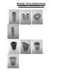
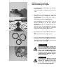
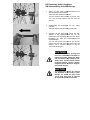
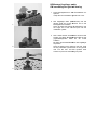
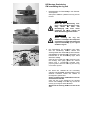
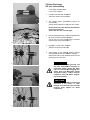
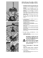
TECHNICAL MANUAL
hub
www.dtswiss.com
HXW19010NMANLS
Inhaltsverzeichnis / Table of contents
Einleitung ...........................................................................................................................................2
Instructions ........................................................................................................................................3
Montage / Demontagewerkzeug .......................................................................................................4
Assembly / disassembly tool ............................................................................................................4
Ersatzteile & technische Daten .........................................................................................................6
Spare parts & technical specification...............................................................................................6
180 ceramic 100mm nondisc..................................................................................................................................... 6
180 ceramic 130mm road Shimano superlight........................................................................................................... 7
180 ceramic 130mm road Campagnolo (9/10 speed) ............................................................................................... 8
180 ceramic 100mm DB center lock and IS............................................................................................................... 9
180 ceramic 135mm DB center lock and IS............................................................................................................. 10
Entfernen der Kassette ....................................................................................................................11
Removing the cassette ....................................................................................................................11
HR Demontage Freilaufkörper ........................................................................................................12
RW disassembling the freewheel....................................................................................................12
HR Demontage Gewindering ...........................................................................................................13
RW disassembling the ring nut .......................................................................................................13
HR Demontage beider Kugellager ..................................................................................................14
RW disassembling both ball bearings ............................................................................................14
HR Montage Kugellager rechts .......................................................................................................15
RW assembling the right ball bearing ............................................................................................15
HR Montage Gewindering ...............................................................................................................16
RW assembling the ring nut ............................................................................................................16
HR Montage Dichtung Nabe/Rotor..................................................................................................17
RW installing the seal hub/rotor .....................................................................................................17
HR Montage Kugellager links..........................................................................................................18
RW installing the left hand bearing ................................................................................................18
HR Montage Freilaufkörper .............................................................................................................19
RW assembling the freewheel.........................................................................................................19
VR Nabe Demontage ........................................................................................................................21
FW hub disassembling ...................................................................................................................21
VR Nabe Montage 180 nondisc und DB CL ....................................................................................22
FW hub assembling 180 nondisc and db cl ...................................................................................22
DT SWISS SERVICE CENTERS .......................................................................................................23
1
Einleitung
Bitte lesen Sie die gesamte Anleitung aufmerksam durch, bevor Sie die Naben einsetzen oder eine Wartung vornehmen.
Die Naben sind in dieser Anleitung im kompletten Laufrad gezeigt. Die Wartung sollte wenn möglich auch im kompletten Laufrad
erfolgen, da sonst einige Arbeitsschritte mit diesen Werkzeugen nicht richtig ausgeführt werden können.
Diese Anleitung richtet sich in erster Linie an Fachhändler mit dem entsprechenden technischen Wissen. Sie vermittelt Ihnen die
grundlegenden Konstruktionsmerkmale der DT Swiss Naben sowie Anleitungen zu deren Wartungs- und Revisionsarbeiten. Bitte beachten
Sie unbedingt, dass für die notwendigen Unterhaltsarbeiten nur Original DT Swiss Spezialwerkzeug benutzt werden darf. DT Swiss AG
behält sich vor, bei unsachgemässer Wartung jegliche Garantiepflicht abzulehnen.
Aufgrund ständiger Verbesserungen der DT Swiss Produkte kann es vorkommen, dass die an Sie ausgelieferte(n) Nabe(n) in Einzelheiten
von der in dieser Anleitung beschriebenen Ausführung abweichen. Für die neuste Version unserer Servicedokumentation oder bei allfälligen
Fragen, wenden Sie sich bitte an die jeweilige Landesvertretung oder sehen Sie auf unserer Homepage http://www.dtswiss.com nach.
Bitte richten Sie Ihre spezielle Aufmerksamkeit auf Hinweise, die unter den folgenden Titeln aufgeführt sind:
ACHTUNG:
Bei Nichtbefolgung dieser Hinweise wird die Funktion der Nabe eingeschränkt und es kann zu Verletzungen mit schwerwiegenden
Folgen und zum Verlust der Produktegarantie führen.
Wichtige Hinweise zur Funktion der Nabe
•
Im Neuzustand hat die Nabe einen erhöhten Rollwiderstand, da das Fett im Freilauf noch nicht verteilt und die Dichtungen noch nicht
eingefahren sind.
•
Radiales einspeichen der DT Swiss Nabe ist nicht zulässig, da es zu unzulässigen Deformationen am Nabenflansch führen kann. DT
Swiss lehnt diesbezüglich jegliche Verantwortung ab. Ausgeschlossen davon sind die speziell für radiales Einspeichen
gekennzeichneten Naben.
•
Bei der Disc Brake Version sind unbedingt die Originalschrauben für die Bremsscheibe zu verwenden !
•
Überprüfen Sie vor jedem Einsatz die Funktionstüchtigkeit Ihrer Hinterradnabe. Stellen Sie fest, ob Freilauf und Kraftschluss
einwandfrei funktionieren. Wenn dies nicht der Fall ist, darf die Hinterradnabe nicht eingesetzt werden. In diesem Fall muss die
Störung vor dem Einsatz behoben werden. Sollten Sie nicht in der Lage sein den Fehler zu beheben, wenden Sie sich an Ihren
Fachhändler, Servicecenter oder sehen Sie auf der DT Swiss Website www.dtswiss.com nach.
•
Bei Nichtbefolgung dieser Hinweise wird die Funktion des Freilaufes eingeschränkt und es kann zu Verletzungen mit schwerwiegenden
Folgen und zum Verlust der Produktegarantie führen.
Wartung und Pflege der Nabe
Die Wartung der Hinter- und Vorderradnabe muss mindestens einmal jährlich durchgeführt werden. Bei regelmässigem Gebrauch unter
extremen Bedingungen (starker Regen, Schlamm, Transport im Regen) muss der Freilauf öfter gewartet werden.
Regelmässige Wartung der Nabe verhilft zu einer längeren Lebensdauer und zu optimalen Fahrleistungen während Jahren.
Durch übermässigen Wasserdruck (z.B. Hochdruckreiniger) kann Wasser in die Nabe eindringen. Verwenden Sie keine Lösungsmittel und
Tenside. Dies kann die Nabe beschädigen.
Garantiebestimmungen
DT Swiss AG mit Sitz in Biel (Schweiz) gewährt für die DT Swiss Produkte ab Kaufdatum zwei Jahre (24 Monate) Garantie auf Material- und
Produktionsfehlern. DT Swiss AG repariert oder ersetzt Produkte, die nach ihrem Ermessen als defekt anerkannt werden. Andere
Ansprüche sind von dieser Garantie ausgeschlossen.
Kein Anspruch auf Garantieleistung besteht bei:
•
•
•
•
•
normaler Abnutzung von Verschleissteilen
unsachgemässer Montage oder in Verbindung mit nicht passenden Produkten
unsachgemässer Instandhaltung, unsachgemässer Reparatur oder Veränderung
unsachgemässem Gebrauch, unsorgfältiger Behandlung, Missbrauch, Nachlässigkeit, grober und leichter Fahrlässigkeit bei Montage,
Wartung und Benutzung, kommerzieller Gebrauch oder Einsatz in Wettkämpfen
Lieferungs- und Transportschäden
DT Swiss AG haftet aus dieser Garantie nicht auf Schadensersatz, insbesondere nicht für indirekte unfallbedingte Schäden, mittelbare
Schäden und Folgeschäden. Zwingende gesetzliche Haftungsregelungen bleiben von dieser Garantie unberührt. Gerichtsstand und
Erfüllungsort ist Biel (Schweiz). Es gilt schweizerisches Recht.
Technische Änderungen bleiben vorbehalten.
Diese Garantiebestimmungen sind weltweit gültig mit Ausnahme von den USA und Canada.
2
Instructions
Please read the entire manual before using the hubs or before carrying out any kind of maintenance work.
In this manual, the hubs are shown installed in a complete wheel. Maintenance work should be carried out on complete wheels
where possible, as some steps can otherwise not be carried out correctly when using these tools.
This manual is intended for retailers with the appropriate skills and knowledge. It details the principle design features of DT Swiss hubs and
also provides instructions as to maintenance and repair work. Please take special care to use only original DT Swiss special tools in order to
undertake the work detailed in this manual. In the event of improper servicing of the hubs, DT Swiss LTD. has the right to refuse any
warranty.
Due to continual improvements that are made to DT Swiss products, it is possible that the hub(s) you have received differ slightly from the
model(s) described in this manual. For the newest version of the service manual or for miscellaneous questions, please consult the official
DT Swiss, representative for the country in which you reside or consult our Internet homepage http://www.dtswiss.com.
Please give special attention to the following notice which is listed under the title bellow:
CAUTION :
In the case of non-compliance with these instructions, the function of the hub will be impaired, which may lead to injuries with
serious consequences, and the loss of the product guarantee.
Maintenance of the hubs
Maintenance of the rear and front hubs wheel must be carried out at least once a year. When used under extreme conditions (heavy rain,
mud, transport in the rain etc.) the free-wheel should be serviced more often.
Regular maintenance of the hub helps to ensure a longer life and optimum running performance for years.
In the case of exposure to water under excessive pressure (e.g. high-pressure cleaners), water may penetrate into the hub. This may
damage the hub. Do not use any solvents or detergents.
Important
•
•
•
•
•
•
Before every use, check the function of your rear wheel hub. Make sure that the free-wheel and engagement connection function
impeccably. Should there be any mal-function, the rear wheel hub must not be used. In such a case, the problem must be repaired
before use. If you are not in a position to repair the hub, contact your dealer, service center or consult the DT Swiss website
www.dtswiss.com.
We strongly recommend that you have your wheels built by an experienced specialist. Proper wheel building is the best way to ensure
that your wheels will last and be problem-free.
New hubs have a higher rolling resistance than used hubs, because the grease in the freewheel has not yet been evenly distributed
and the seals have not yet been bedded in.
Radial lacing on DT Swiss hubs is not recommended as it may lead to impermissible deformations on the hub flange. Flange breakage
is not covered under the warranty in this case.
In the case of the Disc Brake version, the original screws must be used for the brake disc.
Disregarding these instructions will limit the function of the freewheel and can lead to injury or
other severe consequences and the loss of the product warranty.
Warranty terms
This Warranty gives you specific legal rights, and you may also have other rights which vary from state to state.
DT Swiss, Inc., with registered offices in Grand Junction, Colorado, with registered offices in Grand Junction, Colorado, will repair or replace
products that are accepted as being defective at its discretion for a period of 24 months from the date of purchase. In the case a product is
substituted for a defective product, the warranty period will not be extended. This Warranty is extended only to the original purchaser of the
product.
Any implied warranty with this product shall extend no longer than 24 months from the date of purchase. Some states do not allow
limitations on how long an implied warranty lasts, so this limitation may not apply to you.
In order to obtain service under this Warranty, the defective product must be sent, postage prepaid, to the following address after receiving
a return authorization number from technical services (Tel 970-242-9232).
There will be no Warranty service for the following:
•
•
•
•
•
•
•
•
•
Normal wear and tear of parts subject to wear
Incorrect wheel assembly
Alteration of product or use of product in combination with other products that do not fit
Incorrect maintenance or repair
Incorrect use, abuse, misuse, neglect, carelessness, commercial use or use in cycling competitions
Flange breakage
Delivery and transport damage
REPAIR OR REPLACEMENT OF DEFECTIVE PRODUCTS IS THE EXCLUSIVE AND SOLE REMEDY AVAILABLE.
DT SWISS, INC. SHALL NOT BE LIABLE FOR ANY INDIRECT, INCIDENTAL OR CONSEQUENTIAL DAMAGES.
These warranty terms are only valid for USA and Canada.
3
Montage / Demontagewerkzeug
Assembly / disassembly tool
1.
2.
3.
4.
5.
6.
7.
8.
9.
10.
Pos.
1
2
3
4
5
6
7
8
9
10
11
12
11.
Bezeichnung / Description
Lange Montagebuchse / Long installation tool (Ø15/24x60mm)
Kurze Montagebuchse / Short installation tool (Ø15/28x35mm)
Montagewerkzeug Dichtung / Seal installation tool (Ø15/36x10mm)
Demontagewerkzeug Achse / Axle disassembly tool
Montagebuchse für Gewindering / Ring nut installation tool
Achsenhalter Park Tool / Park Tool axle holder
DT Spezialfett / DT special grease
Mehrzweckfett / Multi-purpose
purpose grease
Werkzeugsatz für VR nondisc / Tool kit for front (Pos.9) (Ø17/26x40mm)
Werkzeugsatz für VR / Tool kit for front (Pos.10) ( Ø25/37x27mm)
Spezial Textil-Gewebeband
Gewebeband / Special textile fabric strap
Kunststoffhammer / plastic hammer
Werkzeugsatz komplett (Pos.1-11)
(Pos.1
Tool kit complete (pos.1-11)
12.
Art.No.
HXTXXX00N5025S
HXTXXX00N5024S
HXTXXX00N5026S
HXTXXX00N5031S
HXTXXX00N5027S
HXTXXX00N5001S
HXTXXX00NSG20S
HXTXXX00NMG20S
HWTXXX00NTKRAS
HWTXXX00NTKFRS
HXTXXX00N5139S
HWTXXX00NTK24S
Ersatzteile & technische Daten
Spare parts & technical specification
180 ceramic 100mm nondisc
Ersatzteile – Spare parts
POS.
1
2
3
BEZEICHNUNG
VR Endanschlag Ø17mm, komplett
Kugellager (Ø17x26x5mm) CERAMIC
VR Achse Ø17mm Aluminium
DESCRIPTION
FW adapter Ø17mm, complete
Ball bearing (Ø17x26x5mm) CERAMIC
FW axle Ø17mm aluminium
ART. NO.
HWAXXX00S1545C
HSBXXX00N1922S
HRCXXX00N1544S
Technische Daten – Technical specifications
Einbaubreite / Built-in-width
Gesamtlänge / Overall length
Speichenlochdurchmesser / Spoke hole diameter
Flanschabstand / Flange distance
links / left
rechts / right
Teilkreisdurchmesser / Pitch circle diameter
links / left
rechts / right
Gehäusematerial / Hub shell material
Achsenmaterial / Axle material
Gewicht ohne Schnellspanner / Weight without quick release
100 mm
110 mm
2.4 mm
37 mm
37 mm
39 mm
39 mm
Carbon / Aluminium
Aluminium
~ 96 g
6
180 ceramic 130mm road Shimano superlight
Ersatzteile – Spare parts
POS.
1
2
3
4
5
6
7
8
9
10
11
12
BEZEICHNUNG
HR Endanschlag links, 130mm, komplett
Kugellager (Ø15x24x5mm) CERAMIC
HR Achse Aluminium
Kugellager (Ø15x28x7mm) CERAMIC
Pass-Scheibe
Gewindering Aluminium
Dichtung Nabe/Rotor
Feder
Zahnscheibe superlight
Hülse Alu 15.4mm
Rotor Alu / Shimano sl, komplett
HR Endanschlag rechts, komplett
DESCRIPTION
RW adapter left, 130mm, complete
Ball bearing (Ø15x24x5mm) CERAMIC
RW axle aluminium
Ball bearing (Ø15x28x7mm) CERAMIC
Shim ring
Ring nut aluminium
Seal hub shell/rotor
Spring
Star ratchet superlight
RW spacer 15.4mm
Rotor alu / Shimano sl, complete
RW adapter right, complete
ART. NO.
HWAXXX00S1867S
HSBXXX001923S
HCCXXX00S2181S
HSBXXX00N1924S
HCDXXX00S1083S
HCDXXX00S1110S
HSOXXX00N1031S
HXDXXX00N1087S
HCDXXX00N1742S
HCDXXX00S1077S
HWRCBX00S1741S
HWAXXX00S1043S
Technische Daten – Technical specifications
Einbaubreite / Built-in-width
Gesamtlänge / Overall length
Speichenlochdurchmesser / Spoke hole diameter
Flanschabstand / Flange distance
links / left
Teilkreisdurchmesser / Pitch circle diameter
links / left
Gehäusematerial / Hub shell material
Achsenmaterial / Axle material
Rotor / Rotor
Freilauf / Freewheel
Gewicht ohne Schnellspanner / Weight without quick release
rechts / right
rechts / right
130 mm
140 mm
2.4 mm
33.2 mm
17 mm
41 mm
45 mm
Carbon / Aluminium
Aluminium
Alu; Shimano 8/9 and 10 speed
2 Zahnscheiben / 2 Star ratchets
~181 g
7
180 ceramic 130mm road Campagnolo
(9/10 speed)
Ersatzteile – Spare parts
POS.
1
2
3
4
5
6
7
8
9
10
11
12
13a
13b
BEZEICHNUNG
HR Endanschlag links, 130mm, komplett
Kugellager (Ø15x24x7mm) CERAMIC
HR Achse Aluminium
Kugellager (Ø15x28x7mm) CERAMIC
Pass-Scheibe
Gewindering Aluminium
Dichtung Nabe/Rotor
Feder
Zahnscheibe superlight
Hülse Alu 15.4mm
Rotor Alu/ Campagnolo, komplett
HR Endanschlag Campa rechts, komplett
Lockring Campa für 12er Zahnkranz
Lockring Campa für 11er Zahnkranz
DESCRIPTION
RW adapter left, 130mm, complete
Ball bearing (Ø15x24x5mm) CERAMIC
RW axle aluminium
Ball bearing (Ø15x28x7mm) CERAMIC
Shim ring
Ring nut aluminium
Seal hub shell/rotor
Spring
Star rachet superlight
RW spacer 15.4mm
Rotor alu / Campagnolo, complete
RW adapter Campa right, compl.
Lockring Camp 12 tooth COC
Lockring Camp 11 tooth COC
ART. NO.
HWAXXX00S1867S
HSBXXX001923S
HCCXXX00S2181S
HSBXXX00N1924S
HCDXXX00S1083S
HCDXXX00S1110S
HSOXXX00N1031S
HXDXXX00N1087S
HCDXXX00N1742S
HCDXXX00S1077S
HWRCBX00S1296S
HWAXXX00S1112S
HCDXXX00N1115S
HCDXXX00N1132S
Technische Daten – Technical specifications
Einbaubreite / Built-in-width
Gesamtlänge / Overall length
Speichenlochdurchmesser / Spoke hole diameter
Flanschabstand / Flange distance
links / left
Teilkreisdurchmesser / Pitch circle diameter
links / left
Gehäusematerial / Hub shell material
Achsenmaterial / Axle material
Rotor / Rotor
Freilauf / Freewheel
Gewicht ohne Schnellspanner / Weight without quick release
rechts / right
rechts / right
130 mm
140 mm
2.4 mm
33.3 mm
16.9 mm
41 mm
45 mm
Carbon / Aluminium
Aluminium
Alu; Campagnolo 9/10-speed
2 Zahnscheiben / 2 Star ratchets
~190 g
8
180 ceramic 100mm DB center lock and IS
Ersatzteile – Spare parts
POS.
1
2
3
4
5
BEZEICHNUNG
Center lock Adapter, komplett
VR Endanschlag DB cl links, komplett
Kugellager (Ø15x24x5mm) CERAMIC
VR Achse D B center lock Alu
VR Endanschlag 100X, komplett
DESCRIPTION
Adapter center lock complete
FW adapter db cl left, complete
Ball bearing (Ø15x24x5mm) CERAMIC
FW axle DB center lock alu
FW adapter 100X, complete
ART. NO.
HWZXXX00S1588S
HWAXXX00S1517S
HSBXXX001923S
HRCXXX00N2180S
HWAXXX00S1219S
Technische Daten – Technical specifications
Einbaubreite / Built-in-width
Gesamtlänge / Overall length
Speichenlochdurchmesser / Spoke hole diameter
Flanschabstand / Flange distance
links / left
rechts / right
Teilkreisdurchmesser / Pitch circle diameter
links / left
rechts / right
Bremsaufnahme / Brake interface
Gehäusematerial / Hub shell material
Achsenmaterial / Axle material
Gewicht ohne Schnellspanner / Weight without quick release
Gewicht Center lock Adapter / Weight center lock Adapter
100 mm
110 mm
2.6 mm
22.5 mm
36 mm
44 mm
37.5 mm
Shimano center lock and IS
Carbon / Aluminium
Aluminium
~106 g
~29.5 g
9
180 ceramic 135mm DB center lock and IS
Ersatzteile – Spare parts
POS.
1
2
3
4
5
6
7
8
9
10
11
12
13
BEZEICHNUNG
Center lock Adapter, komplett
HR Endanschlag links, komplett
Kugellager(Ø15x24x5mm) CERAMIC
HR Achse
Kugellager(Ø15x28x7mm) CERAMIC
Pass-Scheibe
Gewindering Aluminium
Dichtung Nabe / Rotor
Feder
Zahnscheibe superlight
Hülse Alu 15.4mm
Rotor Alu / Shimano sl, komplett
HR Endanschlag rechts, komplett
DESCRIPTION
Adapter center lock complete
RW adapter left, 135mm, complete
Ball bearing (Ø15x24x5mm) CERAMIC
RW axle aluminium
Ball bearing (Ø15x28x7mm) CERAMIC
Shim ring
Ring nut aluminium
Seal hub shell/rotor
Spring
Star ratchet superlight
RW spacer 15.4mm
Rotor alu / Shimano sl, complete
RW adapter righte, complete
ART. NO.
HWZXXX00S1588S
HWAXXX00S1528S
HSBXXX001923S
HCCXXX00S2181S
HSBXXX00N1924S
HCDXXX00S1083S
HCDXXX00S1110S
HSOXXX00N1031S
HXDXXX00N1087S
HCDXXX00N1742S
HCDXXX00S1077S
HWRCBX00S1996S
HWAXXX00S1043S
Technische Daten – Technical specifications
Einbaubreite / Built-in-width
Gesamtlänge / Overall length
Speichenlochdurchmesser / Spoke hole diameter
Flanschabstand / Flange distance
links / left rechts / right
Teilkreisdurchmesser / Pitch circle diameter
links / left rechts / right
Bremsaufnahme / Brake interface
Gehäusematerial / Hub shell material
Achsenmaterial / Axle material
Rotor / Rotor
Freilauf / Freewheel
Gewicht ohne Schnellspanner / Weight without quick release
Gewicht Center lock Adapter / Weight center lock Adapter
135 mm
145 mm
2.6 mm
33 mm
19.5 mm
44 mm
47.5 mm
Shimano center lock and IS
Carbon / Aluminium
Aluminium
Aluminium; Shimano 8/9-speed
2 Zahnscheiben / 2 Star ratchets
~206 g
~29.5 g
10
Entfernen der Kassette
Removing the cassette
Die Kassette sollte nur demontiert werden,
wenn die Nabe komplett zusammengebaut ist.
The cassette should only be dismantled if the
hub is completely assembled.
1.
2.
1.
Lockring mit Zahnkranzabnehmer lösen.
Release the lockring using a freewheel tool.
2.
Mit Kunststoffhammer die Zahnkränze gegen Uhr
Uhrzeigersinn leicht lösen.
Loosen the sprockets by lightly tapping it counter
counterclockwise with the synthetic head hammer.
3.
Alle Zahnkränze vom Rotor entfernen.
Remove all the sprockets from the rotor.
4.
Mit Feile die Einkerbungen im Aluminiumrotor
grob entfernen.
Use a file to remove bad notches from the
aluminium rotor.
ACHTUNG:
3.
Der Aluminiumrotor muss gereinigt
und auf seinen einwandfreien Zu
Zustand hin untersucht werden.
Stellen Sie Risse fest, darf dieser
keinesfalls wieder eingesetzt werden,
sondern muss umgehend durch
einen Neuen oder einen Austauschrotor ersetzt werden.
CAUTION:
The aluminium rotor must be cleaned
and inspected. If any cracks or other
damage is visible, the components
must not be re-used,
used, but must be
replaced by a new or a reconditioned
rotor.
4.
HINWEIS:
Die Einkerbungen im Rotor haben keinen ne
negativen Einfluss auf die Funktion des Freilaufes.
NOTE:
Notches on the rotor do not have a negative
influence on the functionality of the freewheel.
HR Demontage Freilaufkörper
RW disassembling the freewheel
1.
Vorsicht: Verkantungsgefahr !
Caution: Ensure the rotor is not tilted !
1.
2.
2.
3.
4.
5.
Rotorseite des Laufrades in Achsenhalter
einspannen. Beidhändig am Laufrad nach Oben
ziehen.
Clamp the wheel into the axle holder. Pull the
wheel with both hands upwards.
Rotor entfernen. Zahnscheibe, Distanzhülse und
Feder aus dem Nabengehäuse entfernen. Zweite
Zahnscheibe und zweite Feder aus dem Rotor
entfernen.
Remove rotor. Remove the star ratchet, spacer
and spring from the hub housing. Remove the
second star ratchet and the second spring from
the rotor.
Wenn sich der Rotor nicht lösen lässt:
If the rotor stucks.
3.
Lockring auf Rotor schrauben.
Screw the lockring again onto the rotor.
4.
Demontagewerkzeug Achse in Rotor.
Put the axle disassembly tool into the rotor.
5.
Rotor mit Abziehwerkzeug demontieren.
Unscrew the rotor with the disasse
disassembly tool.
HR Demontage Gewindering
RW disassembling the ring nut
1.
Montagebuchse für Gewindering in den SchraubSchraub
stock einspannen.
Clamp the installation cylinder for the ring nut into
a vise.
2.
Die Achse des Laufrades in die Vorrichtung
schieben und gegen Uhrzeigersinn kräftig am
Laufrad drehen.
Push the wheel's axle into the cylinder. Spin the
wheel firmly in an anti-clockwise
clockwise direction.
1.
Der Gewindering löst sich, dabei wird die
Dichtung Nabe/Rotor mit aus dem Gehäuse
geschraubt und fällt über die Buchse auf den
Schraubstock.
The ring nut will be loosened and, at the same
time, the hub/rotor seal will also be unscrewed
and will fall over the cylinder onto the vise.
2.
3.
3.
Die Einzelteile mit einem trockenen Lappen reinrein
igen.
Clean the individual parts using a dry cloth.
4.
Das alte Schmierfett im Gewindering muss gründ
gründlich entfernt werden (evtl. Zahnbürste verwenden).
Thoroughly remove the old grease in the ring nut
using a toothbrush if necessary.
ACHTUNG:
Alle Einzelteile müssen gereinigt und
auf ihren einwandfreien Zustand hin
untersucht werden. Stellen Sie Risse
oder eine äussere Beschädigung fest,
dürfen diese Teile keinesfalls wieder
eingesetzt werden, sondern müssen
müs
umgehend durch DT Swiss Original
Originalteile ersetzt werden.
CAUTION:
4.
All components should be cleaned
and inspected. If any cracks or other
damage are visible, the parts must
not be used. They must be replaced
by original DT Swiss components.
HR Demontage beider Kugellager
RW disassembling both ball bearings
1.
Achse mit Hilfe eines Kunststoffhammers aus
dem Gehäuse herausschlagen.
Achse aus dem Gehäuse entfernen.
Use the synthetic head hammer to tap the axle
out of the housing. Remove the axle from the
housing.
1.
2.
2.
Endanschlag und Kugellager von der Achse
schieben.
Slide the adapter and ball bearing off the axle.
3.
Schieben Sie die demontierte Achse um 180°
gedreht in das Nabengehäuse ein, bis die
Achsschulter am Kugellager ansteht. Das zweite
Kugellager mit Hilfe des Kunststoffhammers
herausschlagen
Turn the axle around and insert it into the hub
housing until the axle collar butts against the ball
bearing. Use a synthetic
nthetic hammer to tap the
second ball bearing out.
ACHTUNG:
3.
Alle Einzelteile müssen gereinigt und
auf ihren einwandfreien Zustand hin
untersucht werden. Stellen Sie Risse
oder eine äussere Beschädigung
Be
fest,
dürfen diese Teile keinesfalls wieder
eingesetzt werden, sondern müssen
umgehend durch DT Swiss Origina
Originalteile ersetzt werden.
CAUTION:
All components should be cleaned
and inspected. If any cracks or other
damage are visible, the parts must
not be used. They must be replaced
by original DT Swiss components.
HR Montage Kugellager rechts
RW assembling the right ball bearing
1.
Kurze Montagebuchse in den Schraubstock einein
spannen.
Clamp the short installation cylinder into a vise
vise.
2.
Das Kugellager 6902 (Ø15/28x7mm) auf die
längere Seite der Achse stecken und in die
Montagebuchse schieben.
Place the 6902 ball bearing (Ø15/28x7mm) onto
the longer end of the axle and push into the
installation cylinder.
3.
Das Laufrad mit der Antriebsseite
Antriebsseit auf die Achse
stecken. Die lange Montagebuchse Ø24 auf der
gegenüberliegenden Seite auf die Achse
schieben.
Mit Hilfe des Kunststoffhammers das Kugellager
einpressen.
Place the wheel's drive side over the axle. Push
the long installation cylinder Ø24 on the opposite
side over the axle. Use the synthetic head
hammer to press the ball bearing into place.
1.
2.
3.
HR Montage Gewindering
RW assembling the ring nut
1.
Montagebuchse für Gewindering in den SchraubSchraub
stock spannen.
Clamp the installation cylinder for the ring nut into
the vise.
ACHTUNG:
1.
Bevor Sie den Gewindering monmon
tieren, untersuchen Sie diesen sorg
sorgfältig.
Stellen
Sie
dabei
eine
Beschädigung fest, muss die
dieser
umgehend mit einem original DT
Swiss Gewindering ersetzt werden.
CAUTION:
Before installing the ring nut,
examine it carefully. If the component
is damaged it must be discarded and
replaced immediately by an original
DT Swiss ring nut.
2.
2.
Den Gewindering mit Aussparung nach Oben
über die Verzahnung
zahnung stecken, danach das
Aussengewinde des Gewinderings leicht einfetten
(handelsübliches Mehrzweckfett verwenden). Die
Pass-Scheibe
Scheibe in den Gewindering legen, damit
diese flach aufliegt.
Place the ring nut with the recess uppermost over
the toothing; then
en lightly grease the external
thread using a commercially available multimulti
purpose grease. Place the shim ring into the ring
nut so that it lays flat.
3.
Die Achse des Laufrades in die Vorrichtung
schieben und vorsichtig den Gewindering in das
Gehäuse schrauben, indem das Laufrad im
Uhrzeigersinn gedreht wird.
Achten sie darauf, dass das Gehäuse nicht am
Schraubstock verkratzt.
Insert the axle of the wheel into the clamped
fixtures and carefully screw the ring nut into the
th
housing by turning the wheel clockwise.
Watch that the housing doesn’t scratch at the
vise.
3.
HR Montage Dichtung Nabe/Rotor
RW installing the seal hub/rotor
1.
1.
Die lange Montagebuchse Ø24 in den Schraubstock einspannen.
Clamp the long installation Ø24 cylinder into a
vise.
2.
Rad über die Montagebuchse stecken.
Put the wheel over the installation tool.
WICHTIG:
Bei der Montage der neuen Dichtung
darf nur das rechte Kugellager 6902
(Ø15/28x7mm) im Gehäuse ein
eingepresst sein. Das linke Kugellager
darf erst nach der Montage der
Dichtung eingepresst werden!
IMPORTANT:
2.
When installing a new seal, only the
right hand ball bearing 6902
(Ø15/28x7mm) should be in place.
The left hand ball bearing must not
be pressed in until the seal has been
installed !
Wenn die Dichtung abgenutzt oder defekt ist,
so muss diese unbedingt ersetzt werden.
If the seal shows signs of wear or damage, it
must be replaced immediately.
3.
3.
Die Dichtung auf das Montagewerkzeug für die
Rotordichtung montieren.
Beachten Sie bitte, dass die Dichtung nicht
ni
falsch vormontiert wird.
Place the seal over the rotor seal installation tool.
Ensure that it is placed with the correct
orientation.
4.
Das Montagewerkzeug für die Rotordichtung mit
der vormontierten Dichtung auf die Achse
schieben.
Push the rotor seal installation tool with the seal
on it over the axle.
5.
Die kurze Montagebuchse Ø28 auf die Achse
schieben.
Place the short installation cylinder Ø28 over the
axle.
Dichtung mit Hilfe des Kunststoffhammers in das
Gehäuse einpressen.
Press the seal into the housing by tapping it with
the synthetic head hammer.
4.
5.
HR Montage Kugellager links
RW installing the left hand bearing
1.
2.
1.
Montagebuchse für Gewindering in den Schraub
Schraubstock spannen.
Clamp the installation cylinder for the ring nut into a
vise.
2.
Laufrad mit der Antriebsseite über die Buchse
schieben.
Push the drive side of the wheel over the cylinder.
3.
Die Achse etwa 10mm herausziehen. Das
Kugellager 6802 (Ø15/24x5mm) über die Achse ins
Gehäuse schieben.
Pull out the axle about 10mm. Place the ball
bearing 6802 (Ø15/24x5mm) carefully into the
housing.
4.
Die lange Montagebuchse Ø24 auf die Achse
schieben und mit Hilfe des Kunststoffhammers das
Kugellager 6802 (Ø15/24x5mm)
mm) einpressen.
Place the long installation Ø24 cylinder over the
axle and press the ball bearing 6802
(Ø15/24x5mm) into place by tapping it with the
synthetic head hammer.
Beim Drehen der Achse darf kein
unregelmässiger Widerstand spürbar
sein. Ziehen und drücken Sie an der
Achse um festzustellen ob kein
seitliches Spiel vorhanden ist.
When you turn the axle, you should
not be able to feel any irregular
friction. Push and pull the axle in
order to make sure that there is no
lateral play in the axle.
3.
5.
4.
5.
Mit einem Pinsel das Kugellager leicht einfetten
(handelsübliches Mehrzweckfett verwenden).
Lightly grease the ball bearing using a
commercially available multi-purpose
purpose grease and a
paintbrush.
Kompletten Endanschlag auf die Achse stecken
und andrücken.
Push the complete adapter over the axle and press
it into place.
HR Montage Freilaufkörper
RW assembling the freewheel
1.
1.
Den gereinigten Gewindering im Gehäuse leicht
einfetten (DT Swiss Spezialfett verwenden).
Use DT Swiss special grease to lubricate the
cleaned ring nut inside the hub shell.
2.
Distanzhülse über die Achse bis ans Kugellager
schieben. Feder einsetzen (grosser Durchmesser
auf Lagerring). Die Feder muss nach dem
Einsetzen auf dem Lagerring aufliegen.
Push the spacer over the axle until it butts against
the ball bearing. Insert the spring (large diameter
on ball bearing ring). The
he spring should lay
directly against the ball bearing collar.
3.
Rechte Rotorseite mit einem Lappen reinigen.
Innenverzahnung auf der linken Seite mit einer
Zahnbürste reinigen
Clean the right hand of the rotor with a clean
cloth. Clean the internal toothing on the left hand
with a tooth brush.
2.
Bevor Sie die zweite Feder in den
Rotor legen, müssen die Kugellager
im Rotorgehäuse auf Ihren einwandeinwand
freien Lauf untersucht werden. Sollte
eines nicht
ht in Ordnung sein muss der
Rotor mit einem neuen oder einem
Austauschrotor ersetzt werden.
Before positioning the second spring
into the rotor housing, check that the
rotor ball bearings spin freely without
binding. If any binding or scratching
is detected,
ed, replace the rotor with a
new or reconditioned one.
3.
4.
4.
Die Feder in den Rotor einsetzen, damit der
grössere Durchmesser auf der Pass
Pass-Scheibe
aufliegt.
Place the spring into the rotor with the large
diameter end laying against the shim ring
ring.
Zahnscheiben sorgfältig mit einem trockenen
Lappen reinigen. Beide Zahnscheiben müssen
untersucht werden. Stellen Sie dabei eine
Beschädigung fest, müssen sie umgehend mit DT
Swiss
Originalteilen
ersetzt
werden.
Zahnscheiben gleichmässig mit WENIG Fett
einfetten.
Carefully clean the star ratchets with a dry cloth.
Inspect both star ratchets for damage. If any
damage is visible, the parts must be replaced
using original DT Swiss components. LIGHTLY
grease both star ratchets.
ACHTUNG:
Die Zahnscheiben nicht mit normalem
Fett einfetten, da dies die Funktion der
Stirnradverzahnung beeinträchtigt. Ausschliesslich das von DT Swiss empemp
fohlene Spezialfett verwenden.
CAUTION
5.
5.
6.
:
Never use normal grease in the
freewheel mechanism, because this will
impair the nction of the star ratchet
teeth. Only use DT Swiss recommended
special grease for this procedure !
Beide eingefetteten Zahnscheiben, mit der Ver
Verzahnung gegeneinander, über die Achse legen.
Place both greased star ratchets with the toothing
towards one another over the axle.
6.
Rotor auf die Achse stecken.
Push the rotor over the axle.
Vorsicht : Verkantungsgefahr !
Caution: Ensure the rotor is not tilted !
7.
Rechten Endanschlag gut reinigen und einfetten
(handelsübliches Fett verwenden). Endanschlag
rechts auf die Achse stecken und von Hand
aufdrücken.
Thoroughly clean the right hand adapter and
lubricate it using commercially available grease.
Place the adapter over the right hand end of the axle
and press into place manually.
Vorsicht: Verkantungsgefahr !
Caution: Ensure the adapter is not tilted !
Achten Sie darauf, dass der Endanschlag spürbar
einschnappt !
Ensure that the adapter audibly clicks into place!
8.
Nach der Montage der Nabe muss eine
Funktionsprüfung erfolgen, indem man ruckartig am
Rotor dreht.
After installing the hub, check its function by giving it
a sharp, quick spin.
7.
ACHTUNG:
8.
Wenn die Zahnscheiben nicht einrasten,
ist möglicherweise
weise zuviel Fett im Freilauf
vorhanden oder es wurde ein falsches
Fett verwendet. In diesem Fall etwas Fett
entfernen, resp. das richtige Fett ver
verwenden.
CAUTION:
If the ratchets do not catch, there could
be too much grease inside the rotor, or
the wrong type of grease was used. In
this case, remove some of the grease or
replace it using grease of the correct
type.
VR Nabe Demontage
FW hub disassembling
Lösen beider Endanschläge:
Loosen both adapters.
1.
1.
Laufrad in Achsenhalter einspannen.
Clamp the wheel in the axle holder.
2.
Am Laufrad ziehen (Endanschlag klemmt im
Achsenhalter).
Pull the wheel (adapter is held by the axle holder).
Achten Sie darauf, dass Sie den Schraubstock
nicht zu fest anziehen !
Ensure that the vise is not too tight!
3.
Mit Demontagewerkzeug und Kunststoffhammer
die Achse aus dem Gehäuse schlagen.
Tap the axle out of the housing using a synthetic
head hammer and disassembly tool.
4.
Kugellager von der Achse schieben.
Slide the ball bearing off the axle.
5.
Achse wieder in das Gehäuse stecken und das
zweite Kugellager aus dem Gehäuse schlagen.
Reinsert the axle into the shell and tap the second
ball bearing out of the shell.
2.
3.
ACHTUNG :
Alle Einzelteile müssen gereinigt, und
auf ihren einwandfreien Zustand hin
untersucht werden. Stellen Sie Risse
oder eine äussere Beschädigung fest,
dürfen diese Teile keinesfalls wieder
eingesetzt werden, sondern müssen
umgehend durch DT Swiss OriginalOriginal
teile ersetzt werden.
CAUTION :
4.
5.
All components should be cleaned and
inspected. If any cracks or other
damage are visible, the parts must be
replaced using original DT Swiss
components.
VR Nabe Montage 190 nondisc und DB CL
FW hub assembling 190 nondisc and db cl
1.
190 nondisc Montagebuchse nondisc Ø26 in den
Schraubstock spannen. Neues Kugellager 6803
(Ø17/26x5mm) mit Vorderradachse in die Buchse
schieben.
190 DB CL Lange Montagebuchse Ø24 in den
Schraubstock spannen. Neues Kugellager 6802
(Ø15/24x5mm) mit Vorderradachse in die Buchse
schieben.
190 nondisc Clamp the installation cylinder for
nondisc Ø26 hub into the vise. Push the new ball
bearing 6803 (Ø17/26x5mm) with the front axle
into the cylinder.
190 db cl Clamp the installation cylinder Ø24 into
the vise. Push the new ball bearing 6802
(Ø15/24x5mm) with the front axle into the
cylinder.
2.
Laufrad auf die Achse schieben und Achse ca.
5mm herausziehen.
190 nondisc Zweites Kugellager 6803
(Ø17/26x5mm) auf die Achse schieben und leicht
ins Gehäuse drücken.
190 DB CL Zweites Kugellager 6802
(Ø15/24x5mm) auf die Achse schieben und leicht
ins Gehäuse drücken.
Place the wheel over the axle and pull out the axle
about 5 mm.
190 nondisc Push the second ball bearing 6803
(Ø17/26x5mm) over the axle and press it lightly
into the housing.
190 db cl Push the second ball bearing 6802
(Ø15/24x5mm) over the axle and press it lightly
into the housing.
3.
Mit Hilfe eines Kunststoffhammers beide
Kugellager einpressen.
Press both ball bearings into place using the
synthetic head hammer.
1.
2.
3.
Beim
eim Drehen der Achse darf kein
unregelmässiger Widerstand spürspür
bar sein. Ziehen und drücken Sie an
der Achse um festzustellen ob kein
seitliches Spiel vorhanden ist.
When you turn the axle, you should
not be able to feel any irregular
friction. Push and pull the axle in
order to make sure that there is no
lateral play in the axle.
4.
5.
4.
Beide Kugellager aussen mit einem Pinsel
einfetten
(handelsübliches
Mehrzweckfett
verwenden).
Grease both bearings using a commercially
available multi-purpose
purpose grease and a paintbrush.
5.
Endanschläge auf die Achse stecken und von
Hand aufdrücken.
Position the adapters onto the end of the axle and
press into place manually.
DT SWISS SERVICE CENTERS
Siehe Service Center / see Service Center List :
http://www.dtswiss.com/Service/ServiceCenters.aspx
www.dtswiss.com