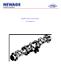
1
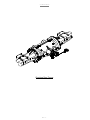
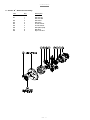
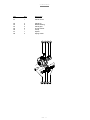
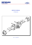
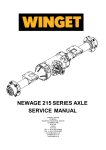
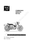
SERVICE MANUAL
915 Series Axle
915 Service Manual
Issue 1 – September 2003
CONTENT:
1 INTRODUCTION
Page – 3 -
2 GENERAL DESCRIPTION
Page – 3 -
3 IDENTIFICATION
Page – 3 -
4 GENERAL SERVICE INFORMATION
.1
4.1 Routine Maintenance
.2
4.2 Lubricants
.3
4.3 Greases
.4
4.4 Brake Fluid – IMPORTANT
.5
4.5 Liquid Sealant
.6
4.6 Fasteners – Tightening Torque
4.7 Axle Backlash Figures
5
Page – 5
Page – 5 Page – 5 Page – 5 Page – 5 Page – 5 Page – 5 Page – 6 -
915 AXLE ASSEMBLIES
Page – 7 -
.7
5.1 Section ‘A’ - Crown Wheel and Pinion Assembly
.8
5.2 Section ‘B’ - Differential Assembly
.9
5.3 Section ‘C’ - Planet Carrier Assembly
Page – 10 Page – 12 Page – 14 -
.10 5.4 Section ‘D’ - Hub Assembly
Page – 16 -
.11 5.5 Section ‘E’ - Axle Main case Assembly
Page – 18 -
.12 5.6 Section ‘F’ - General Parts
6
Page – 7 -
SPIRAL BEVEL GEAR TOOTH CONTACT
Page – 20 -
Page - 2 -
915 Service Manual
1
INTRODUCTION
Spare parts for Newage axles may only be obtained from the original equipment manufacturer and not directly
from Newage. Always quote your vehicle/machine serial number and axle serial number – see section titled
'Identification.'
If possible, the repair/service should be carried out in a clean environment. Where this is not possible and the
work must be completed on site, appropriate measures must be taken to ensure that dirt or foreign matter does
not enter the unit. Newage axles are designed to operate in the arduous conditions found in the construction
industry; providing they are maintained regularly they will provide the service our customers expect from Newage
products.
2
GENERAL DESCRIPTION
The 915 series axle is a double reduction unit, with oil immersed, multi-plate disc brakes.
The centre casing houses the 1st reduction spiral bevel pinion and crown wheel (fixed to a 4 pinion differential),
the oil immersed brakes and the 2nd reduction planetary assembly. The axle shafts are fully floating (i.e. not
subjected to wheel loads) with the wheel hubs supported on opposed tapered roller bearings.
3
IDENTIFICATION
If spares are required, please quote the axle series and the vehicle/machine model and serial number. Newage
axles are produced with a variety of track widths, mounting centres, wheel hub centres, ratios and input
couplings to suit individual customer requirements, therefore it is important to identify the axle correctly
The part number allocated to each axle describes the basic specification as below.
Page - 3 -
915 Service Manual
4
GENERAL SERVICE INFORMATION
4.1 Routine Maintenance
Ÿ
Ÿ
Ÿ
Ÿ
Ÿ
Ÿ
Check for oil leaks around joints and seals:
Check wheel nut tightness:
Check wheel hub bearing adjustment:
Check axle Arm/Main case joint securing bolts:
Check Half Shaft bolts:
Check Prop-Shaft Nuts:
Weekly
Weekly
1,000 hours
Monthly
Monthly
Monthly
4.2 Lubricants
Only those lubricants shown below, or their direct equivalents must be used.
Ÿ
BP SUPER TRANSMISSION S
The oil is added via the combined filler/level plug positioned in the rear of the axle main case (Approximate oil
capacity of 15 litres (26.4 pints)).
•
P80 OIL SEAL LUBRICANT – used when installing new oil seals
4.3 Greases
Pack the gaps between oil seal lips at major overhauls, or whenever a repair to these areas is performed.
Ÿ
CASTROL SPHEEROL L-EP2
4.4 Brake Fluid – IMPORTANT
The axle brakes operate with a mineral hydraulic fluid (ISO VG32). On no account must a "vegetable" based
brake fluid (SAE J1703) be used.
Whenever the brakes are serviced it is essential that the cylinder bores, pistons and seals are clean before
assembly, and may be lightly coated with one of the mineral based fluids shown below.
Ÿ
MOBIL DTE24
4.5 Liquid Sealant
The ‘Axle Arm/Main case’ joint faces must be sealed with any of the following:
Ÿ
Ÿ
LOCTITE "595"
HERMETITE “RED”
4.6 Fasteners – Tightening Torque
Ÿ
Ÿ
Ÿ
Ÿ
Ÿ
Ÿ
Ÿ
Ÿ
spacer
Ÿ
Ÿ
Ÿ
Differential assy. bolt (M12) Grade 10
Differential assy. nut (M12) Grade 10
Diff. bearing carrier shoulder bolt (M10)
Handbrake end cover cap bolts (M6) Grade10
Diff. Bearing carrier tab washer bolts (M6) Grade 8
Differential bearing adjuster nuts
Axle arm-main case bolts (M16)
Coupling nut (M20)
Drag Torque
Wheel nuts. 7/8" B.S.F.
Wheel nuts. 18mm
Axle shaft/Wheel hub bolts (M16)
115 Nm
115 Nm
61 Nm
14 Nm
10 Nm
21 Nm
206 Nm
2.26/2.94Nm
450 Nm
450 Nm
206 Nm
Page - 4 -
(84 lb.ft)
(84 lb.ft)
(45 lb.ft)
(10 lb.ft)
(8 lb.ft)
(15 lb.ft)
(152 lb.ft)
(20/26lb.in) after collapsing
(331 lb.ft)
(331 lb.ft)
(152 lb.ft)
915 Service Manual
4.7 Axle Backlash Figures
Axles
Pin/wheel
Drive Flange
P.C.D.
Backlash
915-2180
(1480 Yoke)
108.05
0.47-0.55
Series (915)
Assy 915-9520
915-2070
915-2080
Page - 5 -
915 Service Manual
5
915 AXLE ASSEMBLIES.
5.1 Section ‘A’ - Crown wheel and Pinion Assembly
Item
A1
A2
A3
A4
A5
A6
A7
A8
A9
A10
A11
A12
Qty
1
1
1
As required
As required
As required
2
1
1
1
1
1
1
1
Description
Spiral bevel wheel
Input drive flange
Spiral bevel pinion
Shim 0.05mm
Shim 0.075mm
Shim 0..25mm
Seal
Collapsible spacer
Bearing cup
Bearing cone
Plain washer
Nut M20
Seal cover
Bearing
Page - 6 -
915 Service Manual
Removing & Servicing the Crown Wheel and Pinion.
1.
Remove the drain plug (E6) and drain the axle oil.
2.
Remove both axle arm assembly’s by removing 12 bolts per side (F4, page 17). Withdraw the planet
carrier assy (see Section C), and sun gear (F7).
3.
Remove annulus (F6) using extractor tool or pinch bars.
4.
Remove the brake spacer plate (F8) and the other brake components (F9 & F10). See Section F. Use
pinch bars at the back of the brake piston (E11) to extract.
5.
Unscrew and remove 4 shoulder screws (E9) and extract the Diff. Bearing Carrier (E3) through the bore
of the Main case (E1). Feed Diff and crown wheel assembly through bore of the Main case.
IMPORTANT: It is essential that a protective sleeve is used over the parts being withdrawn through
the bore to prevent damage to the brake cylinder bore. Failure to observe this procedure will result in
a loss of brake efficiency or complete brake failure.
6.
To remove tab washers (E4) securing the diff housing, release the two screws 2 screws (E23) from Diff
adjusting nut (E2)
7.
Unscrew brg. adjuster nuts (E2) and push brg. cups (E8) out of bores.
8.
While reacting against drive flange to prevent it from turning release the nut (A10) and remove the
washer (A9) from the pinion shaft (A3). Remove the flange (A2). Using a soft drift, remove the pinion from inside
the main case, taking care not to damage the teeth.
9.
Inspect the bearings (A7/A8) for wear and damage. If replacing the inner bearing on the pinion head, use
a bearing puller to extract the cone. Discard collapsible Spacer (A6). Drift out brg; Cups (A7/8) from the main
case bore, taking care not to loose the shims (A4) located behind the brg; cup of the pinion head bore.
IMPORTANT: Once dismantled it is necessary to reset the pinion backlash to ensure the correct
meshing of the crown wheel / pinion. Always use new collapsible spacer (A6) and a new nut (A10).
See section “F” for the crown wheel / pinion setting up procedure.
10.
Record the following information of the original components, in the following sequence.
(a) = The pinion (A3) mounting distance etched on the head (range generally between 115.1>114.9mm).
(b) = The overall bearing seated width of pinion head bearing, (A12)(generally 30.162mm +/- 0.203mm).
(c) = The shim thickness (A4).
(d) = (a) + (b) + (c).
11.
If replacing the pinion (A3) or pinion head bearings (A7, A8) the following procedure needs to be carried
out. Record the following information of the new components to be fitted as follows: (e) = The pinion (A3) mounting distance etched on the head(range generally between 115.1>114.9mm).
(f) = The overall bearing seated width of pinion head bearing, (A12)(generally 30.162mm +/- 0.203mm).
(g) = (e) + (f)
(h) = The new shim thickness (A4) to be determined.
12. New shimming:
New Shim thickness =
(h) = (d) - (g)
Page - 7 -
915 Service Manual
13.
To assemble the unit, reverse the above procedure, and proceed as follows.
14.
Pinion assy. must be fitted before crown wheel/diff assy. Tighten the new pinion nut (A10) until the new
spacer (A6) collapses and the entire end float between the pinion bearings is taken up. Drag torque 2.26 /
2.94Nm (20/26 lb.in). Spin over several times and recheck torque.
Note, the tightening torque to collapse the spacer should not be less than 245 Nm (180 lb.ft).
This equates to a pre-load of 59-98N (13.2-22lbf) for new bearings, or 29.5-59N (6.6-13.2lbf) for used
bearings is obtained. The pre-load is measured by binding a piece of string around the coupling (A2) and
measuring the load to turn the coupling with a spring balance – see drawing below. This must be carried out
with the crown wheel/pinion mesh disengaged.
15.
Fit diff bearing cups (E8) into the main case (E1) and diff brg; carrier (E3). Screw brg; adjuster nut (E2)
loosely to retain Brg; cups in housing bores.
16.
It is advisable to stand main case on its end with the brg. cup (E8) on the bottom. Lower differential
assembly complete with crown wheel through main bore until the bottom bearing (E8) seats in the bearing cup
(E8). See paragraph 5 on page 7.
17.
Fit Diff. Bearing Carrier (E3) so that the 2 tapped holes for locating screws are towards the brake feed
holes on the main case. This is important, as it will allow good oil circulation to other internal
components. Ensure that the shoulder screw holes align with the holes in the main case. Apply silicone
sealant to under the head prior to fitment of the shoulder screw (E9) and repeat three times. Torque to the
recommended figure.
18.
Insert bearing cup through Diff. Bearing Carrier (E3) and loosely fit bearing adjuster nut (E2).
19.
Position Main case (E1) so bore is horizontal.
20.
Adjust both bearing nuts (E2) to obtain the required pinion & wheel backlash. Tighten to the
recommended tightening torque. See section 4-7.
21.
Locate two new tab washers (E4) to both adjusting nuts (E2) fit two screws (E23) and tighten to the
recommended torque.
22.
Ensure all joints are clean and free of the original jointing compound and reseal. Locate each axle arm
assembly on the dowels positioned in the main case, refit the 12 bolts (F4) and tighten to recommended
tightening torque.
23.
Refit drain plug (E6) and refill to the correct level with recommended oil.
Page - 8 -
915 Service Manual
Checking Drag Torque
Page - 9 -
915 Service Manual
1.1 Section ‘B’ - Differential Assembly
Item
Qty
Description
B1
1
1
2
4
2
4
2
8
8
Diff case LH
Diff case RH
Diff wheel
Diff pinion
Thrust washer
Thrust washer
Diff spider (half)
Bolt M12
Nyloc nut M12
B2
B3
B4
B5
B6
B7
B8
Page - 10 -
915 Service Manual
Servicing the Differential Assembly
Note: This procedure assumes the axle is stripped down to main case assembly only.
1.
To remove the annulus (F6) using an extractor tool or pinch bars located behind the annulus in a scissor
fashion.
2.
Remove the brake spacer plate (F8) and the brake components (F9, F10). See Section E. Using pinch
bars at the back of the brake piston (E11) to extract.
3.
Remove the 4 shoulder screws (E9) and extract the Diff. Bearing Carrier (E3) through the bore of the
Main case (E1). Feed Diff and crown wheel assembly through bore of the Main case.
Note: See paragraph 5 page 7.
4.
Remove 2 screws (E23) securing the diff brg; housing, tab washer (E4) to the diff brg; adjuster nut (E2).
5.
Unscrew brg. adjuster nuts (E2) and push brg; cups (E8) out of bores.
6.
Remove the 8 nuts & bolts (B7, B8). The crown wheel (A5) can now be drifted off diff case.
assembly will split into 2 halves. Taking care not to lose internal components.
7.
The
Inspect all gears, bearings and spider for damage and wear. Replace if necessary.
8. To reassemble reverse the procedure.
Important: Great care must be taken when refitting the reassembled diff back into the main. Clearance
is very limited and to avoid personal injury it is advisable lower the fully assembled diff into the case
using a sling made from strong twine.
Note: To reset the backlash see page 7 taking note of paragraph 5 also.
Page - 11 -
915 Service Manual
5.3 Section ‘C’ - Planet Carrier Assembly
Note: This procedure assumes the axle is stripped down to the main assembly only, with planetary
Remaining in place.
1.
The planet carrier assembly can now be removed from the centre casing. Take care not to withdraw the
floating sun gear.
2.
Check the planet gears and the mating gear teeth on the annulus and sun gear for damage and
wear. The planet gears should run free in the planet pins, without excessive radial “play” Replace if
worn. Note: When servicing the planet assembly we recommend all three gears and bearings are replaced. See
section A.
3.
To replace the planet gears, pins or bearings, drift through the spring dowels (C8), which locates the
planet pins (C2) through the planet carrier (C1), lightly drift the planet pins through the planet carrier. Remove
the loose planet gears (C4); thrust washer (C5) and planet brgs; (C3). Remove circlip (C6), which secures the
spacer (C7).
Note: the spacer (C7) is fitted with the chamfer facing outwards.
4.
Remove the old spring dowels (C8) from the planet carrier (C1).
5.
To reassemble: Replace the spacer & circlip (C6, C7) fit the planet brgs; (C3) into planet gears. (C4)
locate the bottom thrust washer, place the planet gear on top of the thrust washer and from the underside gently
tap the planet pin through the carrier, thrust washer & planet gear.
Note: when you begin this procedure it is important that the cross in the planet pin is aligned with the
cross hole in the planet carrier. When part way through fit the top thrust washer and continue to drift the
planet pin all the way through the carrier until it is flush.
6.
Secure by fitting new spring dowel (C8) and peen over the hole in the planet carrier to prevent the spring
dowel from drifting out of position.
7.
Check for free rotation of the planet gears.
8.
To refit to the main case, engage the spline of the sun gear (F). Mesh the planet gears with the annulus
(F6) and push into position.
Page - 12 -
915 Service Manual
Item
Qty
Description
C1
1
Planet carrier
C2
C3
C4
C5
C6
C7
C8
3
6
3
6
1
1
3
Planet pin
Needle bearing
Planet gear
Thrust washer
Circlip
Spacer
Spring dowel
Page - 13 -
915 Service Manual
Page - 14 -
915 Service Manual
5.4
Section 'D' - Hub Assembly
Item
Qty
Description
D1
D2
D3
D4
D5
D6
D7
D8
D9
D10
D11
1
8
8
10
2
1
1
1
1
1
1
Hub (i.e. per side)
Wheel stud
Wheel nut
Bolt M16 x 45mm
Dowel pin
Bearing
Bearing
Hub seal
Spacer
Lock washer
Locknut
Page - 15 -
915 Service Manual
Servicing the Hub Assembly
The hub assembly can be serviced with the axle arm still connected to the main case. Procedure is as follows: 1.
Remove bolts (D4) that secures the axle shaft (F1) to the hub. By drifting the axle shaft off the dowels
and withdraw the shaft. Inspect the spline form for damage and wear. (Flat on hub is provided to aid extraction).
2.
Straighten locking tab ears on lock washer (D10), undo lock nut (D11) remove lock washer (D10) and
bearing spacer (D9).
3.
The hub (D1) can now be withdrawn from the axle arm stub.
Care must be taken not to drop the loose brg. cone.
4.
Examine all brg; cups & cones for wear or damage replace as necessary.
Note: We recommend the hub oil seals are always changed when the hub has been removed.
5.
The bearing cup (D6 & D7) can be drifted out of the hub (D1) if they need replacing. When fitting
new
cups (D6 & D7) ensure that they are aligned squarely to the bores before pressing in.
Note: If the brg. (D7) is replaced oil seal (D8) will also need replacing.
Note: When refitting D8 oil seal, the bore must be cleaned/ degreased and seal lubricant P80 used.
6.
If the oil seal shield (F2) needs replacing it can be drifted off the axle arm. When drifting on the
replacement, care must be taken not to damage the oil seal running diameter.
Before refitting the seal housing ensure all of the original sealant is removed, this may require use of a solvent.
Apply "Loctite" grade 601 to both the to seal housing location point of the arm, and to the seal bore diameter
immediately prior to reassembly. Ensure the seal diameter is free from dirt and damage.
7.
Prior to reassembly of the hub brgs; apply a recommended quality grease to ensure the brgs; are
lubricated on the initial start up.
8.
Note: To adjust the hub bearings.
Ÿ Tighten the lock nut (D11) to a torque of 140 Nm (100 lb.ft). When checking the torque setting turn the wheel
hub a few turns in each direction to ensure the bearings have "seated" correctly and recheck tightening torque.
Repeat this procedure 3 times.
Ÿ
Slacken the nut back a distance equal to 2 tabs of the lock washer (D10).
Ÿ
Bend ear of lock washer over to secure the nut.
9.
To reassemble the hub assembly, clean off the original silicone sealant with a solvent. Reapply a
continuous bead of silicone sealant, and reseal the axle shaft joint to the hub using the same silicone sealant,
reverse the above procedure using a new lock wsher (D10).Note:
To adjust the hub bearings.
Page - 16 -
915 Service Manual
5.5
Section 'E' - Axle Main case Assembly
(See Diagram on page 17)
Item
Qty
E1
E2
E3
E4
E5
E6
E8
1
2
1
2
1
2
2
2
4
1
1
1
1
2
1
1
1
1
2
2
12
2
4
E9
E10
E11
E12
E13
E14
E15
E16
E17
E18
E19
E20
E21
E22
E23
Description
Main case
Bearing Adjustment Nut
Diff. bearing carrier
Lock plate
Breather
Drain plug / level plug
Bearing cup
Bearing cone
Shoulder screw
O-ring small
Brake piston
O-ring large
Bleed valve.
Hand brake operation lever
Brake level return spring RH
Brake level return spring LH
Handbrake lever cover RH
Handbrake lever cover LH
Handbrake lever ‘O’ ring
Handbrake lever ‘O’ ring
Screw M6
Brake lever bush
Screw M6
IMPORTANT: The axle brakes operate with a mineral hydraulic fluid ISO VG32 Specification.
DO NOT USE "Vegetable" based brake fluid (SAE J1703) should not be used.
1.
To gain access to the brakes, the procedure is the same as previously described in section B
2.
When removing the brake plates count them as the number can vary with axle models.
Under normal operating conditions the brakes should last several years. The condition of the brakes
can be checked as follows: Ÿ Paper brake disc (F9) – not less than 4mm thickness.
Ÿ Fixed brake plate (F10) – not less than 2mm thickness. Check for uneven surface wear or heat
discolouration on fixed plate.
3.
The brake piston (E11) can be gently removed from the cylinder using pinch bars in a scissor fashion
locating them behind the piston. Check “o” rings (E10/E12) for wear or damage.
Note: All brake components must be free of damage & remain clean at all times, if in doubt change
the appropriate parts.
4.
To reassemble, reverse the above procedure. Ensure that piston bores are clean and the brake
plates are assembled on the sun gear spline (F7) with the oil feed holes in the sintered plates correctly
aligned for oil circulation.
5.
To remove hand brake operating lever (E14) loosen nut (F14) and bolt (F13) and gently drift the lever from
spline.
6.
Remove 6 M6 cap head bolts (E21) per side and withdraw cover (E17/ E18), spring (E15/E16) and brake
lever LH or RH (F12).
Page - 17 -
915 Service Manual
7.
Repeat steps 6 and 7 for the opposite hand. Note. The cap, spring and brake lever are ‘handed',
and on rebuild must be fitted to the same side of the axle.
8.
Check the condition of the brake lever bush (E22) bore. If this requires replacing drift it through the main
case. Ensure the replacement is fitted square.
9.
To reassemble, reverse the above procedure replacing the brake lever bush “o” rings (E19, E20) with the
brake lever bush (E20).
Page - 18 -
915 Service Manual
5.6 Section 'F' - General parts
Item
F1
F2
F3
F4
F5
F6
F7
F8
F9
F10
F11
F12
F13
F14
Qty
2
2
2
24
6
2
2
2
4
4
1
1
2
2
Description
Axle shaft
Cover wheel hub seal
Axle arm
Bolt M12
Dowel pin.
Annulus
Sun gear
Brake spacer plate
Brake disc
Brake plate
Brake lever RH
Brake lever LH
Bolt M10
Nyloc Nut M10
Page - 19 -
915 Service Manual
SAFETY: Prior to removal of an axle arm we recommend that lifting tackle is available, due to the
weight of the associated components.
1 Making sure the weight is fully supported, remove the bolts (F4) around the flange of the axle arm connecting
it to the main case and withdraw the axle arm (F3).
Note this can be done with or without the hub assembly fitted to the arm.
2.
Before refitting the axle arm, ensure the mating faces on the axle arm flange and centre case are
clean and free of damage.
Apply a continuous bead of the recommended sealing agent (see section 4.5).
3.
Locate axle arms on main case dowels with mounting pad on arm upper- most.
4.
Apply approved tightening torque (section 4.6 page 4) to the axle arm bolts diametrically opposed and
draw arms onto main case dowels & joint face.
5.
Refill with recommended oil to the correct level.
Page - 20 -
915 Service Manual
1
SPIRAL BEVEL GEAR TOOTH CONTACT
Contact may vary, but
approximately in the
spaced between root
may be towards toe on
flanks,
or
marking
towards toe on convex
concave flank or vice
generally
is
tooth centre, equiand tip. The marking
some gears on both
crossed slightly i.e.
flank and heel on
versa.
If, compared to the
factory
contact, the contact appears as shown below, then corrective action should be taken as follows:
1.1 ERROR 1: Pinion too far out of mesh
Convex flank
Contact further to
toe and tip than
factory marking.
Concave flank
Page - 21 -
tooth
915 Service Manual
Contact further to heel and tip than factory marking.
ACTION: Recheck and decrease shims below pinion cartridge flange.
Page - 22 -
915 Service Manual
1.2 ERROR 2: Pinion too far into mesh
Convex flank
Contact further to heel and root rather than factory marking.
Concave Flank
Contact further to toe and root than factory marking.
ACTION: Recheck and increase shims below pinion cartridge flange.
Page - 23 -
915 Service Manual
This page is intentionally left blank.
Page - 24 -