1
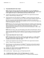
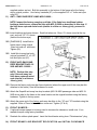
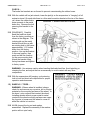
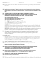
FORM #9666.05-092605 PRINTED IN U.S.A. PAGE 1 OF 10 6” Lift System for 1999 and newer Ford F-250 / 350 Super Duty 4WD Pickup INSTALLATION INSTRUCTIONS INTRODUCTION Installation requires a professional mechanic. Prior to beginning, check all suspension-to-frame attaching points for stress cracks. The overall vehicle must be in excellent working condition; repair or replace all worn parts. Read instructions several times before starting. Be sure you have all needed parts and know where they install. Read each step completely as you go. NOTES: • The rear lift is sold separately and includes separate installation instructions. • Save all factory mounting hardware for reuse, unless otherwise noted. • A factory service manual must be on hand. The manual will contain fastener torque specifications, assembly techniques, and / or special tool requirements that are unique to this particular year and model vehicle. • Do not add or fabricate any components to gain additional suspension height. • Prior to attaching components, be sure all surfaces are free of grit, grease, undercoating, etc. • A torque specification in foot-pounds is shown in parenthesis “( )” after each fastener. • Use the check off box “” found at each step to help you keep your place. Two “” denotes that one box is for the driver side and one is for the passenger side. PARTS LIST … The part number is stamped into each part or printed on an adhesive label. Identify each part and place the appropriate mounting hardware with it. PART NO DESCRIPTION NEW ATTACHING HARDWARE (Qty.- if more than one) (Qty.- if more than one) 01-216-6 ...................... (2) front leaf spring, diesel, V-10 OR 01-225-6 ...................... (2) front leaf spring, gas V-8 FORM #9666.05-092605 PRINTED IN U.S.A. PAGE 2 OF 10 55-03-9660................... (2) front anti-sway bar drop ......... (4) bushing link (2) sleeve, 12mm ID early style anti-sway bar links (2) sleeve, 1/2" ID (2) 1/2" x 2-1/2" bolt (2) 1/2" Nyloc nut OR 55-18-9660................... front anti-sway bar drop ............... (1) 12mm x 80mm bolt bracket, passenger side (1) 12mm stover nut 55-19-9660................... front anti-sway bar drop ............... (1) 12mm x 80mm bolt bracket, driver side (1) 12mm stover nut late style anti-sway bar links 55-07-9660................... track bar bracket .......................... (1) 5/8” x 3-1/2” bolt (1) 5/8” nyloc nut 01-1109 ........................ pitman arm models made on or prior to 2/28/99 OR 55-07-9662................... track bar bracket 01-1112 ........................ pitman arm models made on or after 3/1/99 55-06-9660................... (2) compression travel ................. (4) 3/8” x 1” bolt stop extension, front (4) 3/8” nyloc nut 01-300 .......................... (2) polyurethane bumpstop,......... (2) 3/8” lock washer front (2) nut 55-06-9660................... (2) compression travel ................. (2) 7/16” x 1-3/4” bolt stop extension, rear (2) 7/16” nyloc nut (2) 7/16” ID sleeve 85144 ........................... (2) shock absorber, front ............. (2) shock boot*, tie, decal (2) hardware pack 85168 ........................... (2) shock absorber, rear .............. (2) shock boot*, tie, decal (2) hardware pack *(Note: Shock boots, if desired, purchased seperately) 0034 ............................. Superlift badge ............................ alcohol wipe pad 00461 ........................... decal, “Warning To Driver” INSTALLATION PROCEDURE 1) PREP ARE VEHICLE... Place vehicle in neutral. Raise front of vehicle and secure a jack stand beneath each frame rail, behind the front spring shackles. Ease the frame down onto the jack stands. Leave the jack under the axle to support it while the suspension is disassembled. Place transmission in low gear or “park”, and chock rear tires. Remove front tires. FORM #9666.05-092605 PRINTED IN U.S.A. PAGE 3 OF 10 2) REMOVE FRONT BUMPER... Using a clip tool or a large flat head screwdriver, disconnect the rubber splash panel from beneath the front bumper. Disconnect the block heater plug “Christmas tree” clip from the bumper (if so equipped). Remove the four bumper-to-frame bolts and lay the bumper aside. 3) TRACK BAR / ANTI-SW AY BAR… NOTE: The track bar’s lower end attaches to the passenger side of the front axle. It’s upper end mounts to a bracket that ties into the passenger side frame rail and the primary frame crossmember. Disconnect the track bar from it’s upper mounting bracket and let the bar hang. Now unbolt the bar’s upper end mounting bracket. NOTE: On each side, anti-sway bar links span from the sway bar body up to the frame rails. Remove the anti-sway bar links. Remove the factory shock absorbers. NOTE: On each side, a rubber compression travel stop is bolted to the bottom of the frame rail, just inboard of the shock absorbers. Remove the compression travel stops. 4) FRONT LE AF SPRING REMOV AL... Leaf spring removal and installation (steps 4 and 5) is performed one side at a time. Start with the driver side. Position the floor jack under the driver side knuckle. Load the jack so that it supports, not raises, the axle; the frame rail is to remain securely on the jack stand. Remove the two spring-to-axle U-bolts. Now remove the top U-bolt / shock plate and the bottom U-bolt cradle. Remove the spring shackle bolt and swing the shackle back and away from the spring. Unbolt the spring’s front eye from it’s hanger, then lower the jack enough to allow spring removal. 5) SUPERLIFT SPRINGS... There is not a designated front or rear spring eye; both ends are dimensionally the same. It is easiest to insert the Superlift spring from front of vehicle. Position the spring eye in the front hanger and install the factory bolt from the inside, facing outward. Install factory retaining nut and hand tighten only. The bolt is fully tightened in a later step when the suspension is supporting vehicle weight. FORM #9666.05-092605 PRINTED IN U.S.A. PAGE 4 OF 10 Position the spring onto the axle. Raise the jack and mate the rear spring eye to the shackle. Insert factory bolt from the inside, facing outward. Install factory nut and hand tighten only. Position top U-bolt plate, and bottom U-bolt cradle, and install the supplied U-bolts. Snugup, do not fully tighten U-bolts. As with the spring eye bolts, they are fully tightened later. Repeat steps 4 and 5 on passenger side. 6) PITMAN ARM #01-1109 OR #01-1112… Inspect all steering link ends for looseness and/or wear and replace as necessary. Center the steering wheel so that the tires (if they were on the vehicle), point straight ahead. Make a note of the factory pitman arm’s position in relationship to the steering box/frame. Remove the cotter key and jam nut on the drag link where it attaches to the pitman arm. Use a pickle fork or other suitable tool to separate the drag link. Remove the jam nut on the end of the sector shaft. Using a pitman arm puller tool (available at most auto parts stores), separate the pitman arm from the sector shaft. IMPORTANT: Prior to installing the dropped pitman arm, compare the spline count and indexing lugs of the stock pitman arm with the supplied pitman arm to verify the correct arm has been applicated for the vehicle. This can be accomplished by stacking the stock arm on the supplied arm (see DIAGRAM 1). The splines and indexing lugs must line up exactly. If a difference is noted (i.e. the pitman arms do not line up), contact Superlift before proceeding. Position the Superlift pitman arm (#01-1109 on models made prior to 2/28/99 or #01-1112 on models made on or after 3/1/99) on the sector shaft in the exact same position as the original arm. Reinstall the factory jam nut and tighten (200) Reconnect the drag link to the pitman arm, install the jam nut, and tighten (67). Once the nut is torqued, install a new cotter key. FORM #9666.05-092605 7) PRINTED IN U.S.A. PAGE 5 OF 10 TRACK BAR BRACKET #55-07-9660… NOTE: Perform this step only if the vehicle was made on or prior to 2/28/99. For vehicles made on or after 3/1/99, proceed to step 8. The production date can be found on the upper left corner of a label located on the driver side door post. Install the new Superlift track bar bracket #55-07-9660 in the original track bar bracket location. Reuse the factory fasteners (130). Attach the upper end of the track bar to the upper “07” bracket mounting hole using the supplied 5/8” x 3-1/2” bolt and 5/8” nyloc nut. The track bar sleeve clearance is tight for this bolt and it may require some light taps with a hammer to seat fully; use caution not to damage the bolt threads.The bolt should be installed from front to rear and hand tighten only. It will be fully tightened in a later step. NOTE: Because of the extremely tight clearance between the supplied track bar bolt and the sleeve in the upper end of the track bar, it may be necessary on some vehicles to drill out the upper track bar sleeve using a 5/8” drill bit. If this becomes necessary, it is strongly recommended that the track bar be removed from the vehicle and placed in a vise or other suitable fixture for drilling. NOTE: While the factory upper track bar hardware will fit with the Superlift bracket, failure to replace the factory hardware with the supplied 5/8” bolt will result in an intermitent “popping” noise, especially while turning, due to excessive clearance between the factory bolt and sleeve. 8) TRACK BAR BRACKET #55-07-9662... NOTE: Perform this step if the vehicle w as was made on or after 3/1/99. The production date can be found on the upper left corner of a label located on the driver side door post. Install the new Superlift track bar bracket #55-07-9662 in the original track bar bracket location. Reuse the factory fasteners (130). Attach the upper end of the track bar to the lower “07” track bar mounting hole using the factory hardware. Insert the bolt from front to rear and hand tighten only; the bolt is fully tightened in a later step. 9) SUPERLIFT FRONT SHOCK ABSORBERS #85144... Install shock bushings, boot, and decal. Install the shock. Tighten the upper nut (76) and lower bolt (76). 10) COMPRESSION TRAVEL STOP EXTENSIONS #55-15-9660... On each side, attach a #01-300 poly bumpstop to a “15” extension bracket using the FORM #9666.05-092605 PRINTED IN U.S.A. PAGE 6 OF 10 supplied washer and nut. Bolt this assembly to the bottom of the frame rail at the factory stop’s original position. Use factory hardware (67) or the supplied 3/8” x 1” bolts and nyloc nuts (23). 11) ANTI – SWAY BAR DROP LINKS #55-03-9660... NOTE: Inspect the factory sway bar end links. If the links have traditional rubber bushings and sleeves, replace the links with #55-10-9660 as described in this step. If the links have captured swivel ends (similar to a Heim or Johnny joint), proceed to Step 12. Insert bushings and wear sleeves. Each link takes one 12mm I.D. sleeve (used at the top eye), and one 1/2" I.D. sleeve (used at the bottom eye). [DIAGRAM 2] Install link-toframe mount using original 12mm bolt and nut as shown. Tighten (60). Install link-to-sway bar body using a furnished 1/2" x 2-1/2" bolt and Nyloc nut (57). 12) FRONT ANTI-SWAY BAR DROP BRACKETS #55-189660 AND #55-19-9660… NOTE: Perform this step only if the anti-sway bar links have captured swivel ends (similar to a Heim or Johnny joint). Remove the factory anti-sway bar frame brackets (where the upper end of the sway bar link attaches to the frame). Save all hardware for reuse. Attach the Superlift anti-sway bar drop brackets (#55-18-9660 passenger side and #55-199660 driver side) to the frame in the same location as the original brackets using the factory hardware. Tighten to factory specs. Attach the upper end of the factory anti-sway bar links to the “18” and “19” brackets using the supplied 12mm x 70mm bolt and 12mm stover nut. Tighten (37 lb-ft). 13) FRONT BUMPER... If optional bumper spacer kit is being used to increase tire clearance, install now. If not, reattach bumper using factory hardware. Reattach the rubber splash panel. Insert the block heater wiring loom “Christmas tree” plug. 14) FRONT BRAKE LINE BRACKET RELOCATION and INITI AL CLE AR ANCE FORM #9666.05-092605 PRINTED IN U.S.A. PAGE 7 OF 10 CHECK... The brake line brackets are re-formed to prevent overextending the rubber hoses. With the vehicle still on jack stands, lower the jack(s) so the suspension is “hanging” at full extension travel. On each side there is a thin metal mounting bracket at the top of the frame rail, where the rubber brake hose connects to the metal brake line. Remove the bolt securing this bracket to the frame. [DIAGRAM 3] Carefully bend the hard line down from the factory position as shown in the diagram. The indexing tab on the metal bracket should line up with an existing hole in the frame approximately 1-1/2 inches down from the factory position. Line up the bracket in the new location, then mark and drill the location for the new mounting hole. Attach the bracket using factory hardware and tighten to factory specs. WARNING: Use extreme caution when bending the brake hard line. Avoid pinching or crimping the line, and adjust the line as necessary to avoid contact with any other components. With the suspension still hanging, cycle steering lock-to-lock and check all components for proper operation and clearances. 15) WHEELS / TIRES... WARNING: When a wheel is installed, always check for and remove any corrosion, dirt or foreign material on the mounting surfaces of the wheel, or the drum / rotor surfaces that contact the wheel. Installing wheels without proper metal-to-metal contact at the wheel mounting surfaces can cause the lug nuts to loosen and the wheel to come off while the vehicle is in motion. NOTE: Inspect the lug nut and washer assemblies. Replace the assembly if the washer portion will not spin freely. FORM #9666.05-092605 PRINTED IN U.S.A. PAGE 8 OF 10 Position wheel / tire onto vehicle. Turn the wheel until one lug is at the top of the wheel hub bolt circle. Install the lug nuts loosely. Tighten the lug nuts only until snug using the lug nut tightening pattern shown in [DIAGRAM 4] to minimize runout. The lug nuts are fully tightened in a later step. 16) TORQUE SPECIFICATIONS and FINAL CLE AR ANCE CHECK... Raise vehicle and remove jack stands. Lower the vehicle to the ground so that the suspension is supporting the weight of the vehicle. Torque the following: 1) spring-to-axle U-bolts (99) 2) front leaf springs, rear (shackle) eye (185) 3) front leaf springs, front eye (259) 4) 5/8” track bar eye bolt, upper end (112) OR factory track bar eye bolt, upper end (129) 5) [DIAGRAM 4] wheel lug nuts (148) CAUTION: Failure to tighten the lug nuts in the sequence shown can result in high tire and wheel runout, which speeds up the development of brake roughness, shudder and vibration. WARNING: Retighten lugs at 500 miles after any wheel change, or anytime the lug nuts are loosened. Failure to do so could cause wheels to come off while vehicle is in motion. Once again, cycle the steering lock-to-lock (suspension loaded) and inspect the tires / wheels, steering, suspension and brake systems for proper operation, tightness and adequate clearances. 17) RE AR LIFT... Superlift’s rear block lift includes it’s own generic installation instructions. To eliminate any possible confusion, we are verifying here that the Superlift lift blocks seat against the axle, and the factory spacers are placed on top of the Superlift blocks. Torque specification for the Superlift 5/8” diameter U-bolts and Nyloc nuts is (185). 18) REAR COMPRESSION TRAVEL STOP EXTENSIONS #55-06-9660… On each side, unbolt the factory rear compression travel stops attached to the bottom of the frame. Save the factory nut for reuse Attach the original compression travel stops to the #55-06-9660 extension brackets. The supplied 7/16” ID sleeve should be installed under the factory nut to compensate for the excessive stud length of the factory snubber. Attach the #55-06-9660 bracket to the bottom of the frame at the stop’s original position using the supplied 7/16” x 1-3/4” bolt and nyloc nut. Tighten (37). 19) SUPERLIFT RE AR SHOCK ABSORBERS #85168... Remove the factory shock absorber. The lower end of the shock is attached to bracket, which in turn, attaches to the axle tube via FORM #9666.05-092605 PRINTED IN U.S.A. PAGE 9 OF 10 a U-bolt. To shorten the required shock length, loosen the U-bolt and rotate the shock attachment point up. There is a bracket locating tit on the axle tube; the bracket / U-bolt assembly will rotate up until the U-bolt makes contact with the tit. Evenly tighten the U-bolt nuts: Ford axle (35), Dana axle (46). Install the shock bushings, boot and decal. Install the shock. Tighten both shock eye mounts (46). 20) HE ADLIGHTS... Readjust headlights to proper setting. 21) SUPERLIFT NAME BADGE and WARNING DECAL. .. The system includes one 2" x 5" name badge (#0034). Additional and / or larger badges are available from Superlift or a Superlift dealer. We suggest putting the badges on the front fenders, tailgate, or rear window. The badge mounts by means of factory applied, doublebacked tape. Follow these instructions to ensure that badge sticks properly: Clean designated area with warm, soapy water. Rinse and wipe dry with a soft, lint free towel. Thoroughly prep the area with the furnished alcohol wipe pad and wipe dry with a soft, lint free towel. Do not touch the surface again with your hands; they transfer body oils. Remove mounting tape backing, line up badge, and press in place. Do not touch mounting tape or allow tape to get dirty. Press firmly on the badge face and hold a few seconds to seat mounting tape. A superior adhesive bond forms over time. We recommend allowing 24 hours of cure time before washing and waxing. The emblem itself can be cleaned with any glass cleaner. Install the “WARNING TO DRIVER” decal on the inside of the windshield, or on the dash, within driver’s view. Refer to the “NOTICE TO DEALER AND VEHICLE OWNER” section on the back page. IMPORTANT PRODUCT USE INFORMATION As a general rule, the taller a vehicle is, the easier it will roll over. Offset, as much as possible, what is lost in roll over resistance by increasing tire track width. In other words, go “wide” as you go “tall”. Many sportsmen remove their mud tires after winter / hunting season and install ones more appropriate for street driving; always use as wide a tire and wheel combination as possible to enhance vehicle stability. We strongly recommend, because of roll over possibility, that the vehicle be equipped with a functional roll bar and cage system. Seat belts and shoulder harnesses should be worn at all times. Avoid situations where a side rollover may occur. Generally, braking performances and capabilities are decreased when significantly larger / heavier tires and wheels are used. Take this into consideration while driving. Do not add, alter, or fabricate any factory or aftermarket parts to increase vehicle height over the intended height of the Superlift product purchased. Mixing component brands is not recommended. Most states have some type of law limiting vehicle height. The amount of lift allowed, and how the lift may FORM #9666.05-092605 PRINTED IN U.S.A. PAGE 10 OF 10 be achieved, varies greatly. Several states offer exemptions for farm or commercially registered vehicles. It is the owner’s responsibility to check state and local laws to ensure that their vehicle will be in compliance. Superlift makes no claims regarding lifting devices and excludes any and all implied claims. Superlift will not be responsible for any altered product or any improper installation or use of our products. We will be happy to answer any questions concerning the design, function, and correct use of our products. IMPORTANT MAINTENANCE INFORMATION It is the ultimate buyer’s responsibility to have all bolts / nuts checked for tightness after the first 100 miles and then every 1000 miles. The steering, suspension and driveline systems, along with wheel alignment should be inspected by a qualified professional mechanic at least every 3000 miles. NOTICE TO DE ALER AND VEHICLE OWNER Any vehicle equipped with a Superlift lifting device must have the enclosed “Warning to Driver” decal installed on the inside of the windshield or on the vehicle’s dash, within driver’s view. The “Warning to Driver” decal is to act as a constant safety reminder for whoever may be operating the vehicle. The WARRANTY IS VOID unless this decal is in place. INSTALLING DEALER... It is your responsibility to install warning decal and forward these installation instructions to the vehicle owner for review of warnings, product use and maintenance information. Replacement warning decals are available free upon request. These instructions are to be kept with the vehicle registration papers and owners manual for the service life of the vehicle. SUPERLIFT LIMITED LIFETIME W ARRANTY Suspension products bearing the Superlift (LKI Ent.) name are warranted for as long as the original purchaser owns the vehicle that the LKI product was originally installed on. This warranty is nontransferable. Warranty covers only the product, no labor, time loss, or freight incurred. Any product that has been abused, altered, incorrectly installed, or used in competition is not covered. Product finish, spring bushings, Polyurethane products, and normal wear is not covered. The LKI product is subject to replacement or repair. No other warranties are expressed or implied. An authorized Superlift dealer must inspect the part in question and confirm that the “Warning to Driver” decal is properly displayed. A copy of the sales invoice is required for warranty consideration. SUPERLIFT SUSPENSION SYSTEMS 300 Huey Lenard Loop Rd. West Monroe, Louisiana 71292 Phone: (318) 397-3000 Sales / Tech: 1-800-551-4955 FAX: (318) 397-3040 Web Site: www.superlift.com