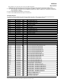
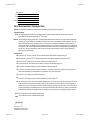
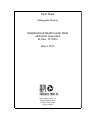
1
Tel 713 871 8484 Fax 713 871 8440 Project: Addendum No: Far East Clinic 1521 Joe Battle Blvd. El Paso, Texas 79936 Neighborhood Health Center West 6600 North Desert Blvd. El Paso, Texas 79912 Architect’s Project No. Date of Issue: 5/19/2015 Contract For: General Construction For Bids Due: May 28, 2015 414018 & 414019 From: Karen Killingsworth, AIA Page Southerland Page, Inc. 1100 Louisiana, Suite One Houston, TX 77002 Owner: Maria Zampini, COO University Medical Center of El Paso 4815 Alameda Ave. El Paso, Texas 79905 Distribution: Page Southerland Page, Inc. 1100 Louisiana, Suite One Houston, TX 77002 Pagethink.com Owner Consultant(s) Bidders Description: 1. 2. 3. 4. 5. 6. 7. 8. 9. 10. 11. 12. 13. 14. Far East Landscape Drawings: Shift landscape areas near the entry. Far East Landscape Drawings: Adjustments to plant locations and quantity throughout the site. Far East Landscape Drawings: Adjustments to the Landscape Ordinance calculations. Far East Landscape Drawings: General adjustments to the irrigation system throughout the site. West Clinic Landscape Drawings: Shift the majority of the landscape areas throughout the site. West Clinic Landscape Drawings: Adjustments to plant locations and quantity throughout the site. West Clinic Landscape Drawings: Adjustment of the size and location of the "native area." West Clinic Landscape Drawings: Adjustments to the Landscape Ordinance calculations. West Clinic Landscape Drawings: General adjustments to the irrigation system throughout the site. Landscape drawings issued in this addendum have revised sheet numbers ending with the designation “-R” to represent a revision to that sheet. Revisions of Architectural Site Plan at Neighborhood Health Center West and Far East to clarify notations and site element types and locations. Clarification of quantity and location of benches at exterior. Clarification of exterior section and plan details with regard to sheet waterproofing, foil-faced rigid insulation, and air barrier. Clarification of exterior section and plan details with regard to connections between curtain wall system and back up. The following items are to be integrated into the drawings as additions or deletions to the documents issued for construction: A) Sheet A-682 – ARCHITECTURAL – INTERIOR COLOR/MATERIAL LEGEND AND DETAILS, Interiors - Color/Material Schedule: PSP Project No. 414019 & 414018 Printed 5/19/2015 Path: P:\414019\C-ConstAdmin\C02b Addenda\Addendum-2015-05-19.docx Page 1 of 3 ADDENDUM May 19, 2015 Epoxy terrazzo: TZ-1, TZ-2, TZ-3, TZ-4, TZ-5, TZ-X, Add in Comments: “AGGREGATE AND COLOR TO MATCH EXISTING EPOXY TERRAZZO AT UMC HOSPITAL MAIN ENTRY LOBBY AREAS.” 15. The following items are to be integrated into the specifications as additions or deletions to the documents issued for construction: 1. Section 087100 Door Hardware – 3.8 Door Hardware Schedule: Revise All door hardware sets containing the electrified locks marked L9093EU to L9092EU. 16. Refer to attached Civil Sheet modifications for further items. 17. Refer to attached MEP Addendum Description for further items. Revised Drawing List: This addendum includes drawing sheets that have been added or revised as of May 19, 2015. Please replace any prints from the original issue set with those below marked "R", and ADD sheets marked "A" to your bidding documents. Sheet No. FC-100 FC-101 FC-102 FC-200 FC-201 FC-300 FC-400 FC-500 WC-100 WC-101 WC-102 WC-200 WC-201 WC-300 WC-400 WC-500 C-600 C-601 C-604 C-606 C-607 L-100-R LC-101-R LC-102-R LC-103-R LP-101-R LP-102-R LP-103-R LI-101-R LI-102-R LI-103-R L-100-R LC-101-R LC-102-R LC-103-R LP-101-R LP-102-R LP-103-R LI-101-R LI-102-R LI-103-R AS-101 FAS-101 A-501 A-502 A-503 A-504 A-505 A-511 A-512 P-102 P-406 P-612 M-511 Revision Date 05/19/2015 05/19/2015 05/19/2015 05/19/2015 05/19/2015 05/19/2015 05/19/2015 05/19/2015 05/19/2015 05/19/2015 05/19/2015 05/19/2015 05/19/2015 05/19/2015 05/19/2015 05/19/2015 05/19/2015 05/19/2015 05/19/2015 05/19/2015 05/19/2015 05/19/2015 05/19/2015 05/19/2015 05/19/2015 05/19/2015 05/19/2015 05/19/2015 05/19/2015 05/19/2015 05/19/2015 05/19/2015 05/19/2015 05/19/2015 05/19/2015 05/19/2015 05/19/2015 05/19/2015 05/19/2015 05/19/2015 05/19/2015 05/19/2015 05/19/2015 05/19/2015 05/19/2015 05/19/2015 05/19/2015 05/19/2015 05/19/2015 05/19/2015 05/19/2015 05/19/2015 05/19/2015 05/19/2015 Status R R A R A R R R R R A R A R R R R R R A A R R R R R R R R R R R R R R R R R R R R R R R R R R R R R R R R R Sheet Title CIVIL DEMOLITION PLAN CIVIL SITE PLAN ALTERNATE PAVING PLAN GRADING PLAN GRADING SECTIONS DRAINAGE PLAN UTILITY PLAN STORM WATER POLLUTION PREVENTION NOTES CIVIL DEMOLITION PLAN CIVIL SITE PLAN ALTERNATE PAVING PLAN GRADING PLAN GRADING SECTIONS DRAINAGE PLAN UTILITY PLAN STORM WATER POLLUTION PREVENTION NOTES STANDARD DETAILS STANDARD DETAILS WATER AND SEWER DETAILS CONCRETE PAVING DETAILS CURB INLET DETAILS FAR EAST-LANDSCAPE MASTER PLAN FAR EAST-LANDSCAPE CONSTRUCTION PLAN FAR EAST-LANDSCAPE CONSTRUCTION PLAN FAR EAST-LANDSCAPE CONSTRUCTION PLAN FAR EAST-LANDSCAPE PLANTING PLAN FAR EAST-LANDSCAPE PLANTING PLAN FAR EAST-LANDSCAPE PLANTING PLAN FAR EAST-LANDSCAPE IRRIGATION PLAN FAR EAST-LANDSCAPE IRRIGATION PLAN FAR EAST-LANDSCAPE IRRIGATION PLAN FAR EAST-LANDSCAPE MASTER PLAN WEST-LANDSCAPE CONSTRUCTION PLAN WEST-LANDSCAPE CONSTRUCTION PLAN WEST-LANDSCAPE CONSTRUCTION PLAN WEST-LANDSCAPE PLANTING PLAN WEST-LANDSCAPE PLANTING PLAN WEST-LANDSCAPE PLANTING PLAN WEST-LANDSCAPE IRRIGATION PLAN WEST-LANDSCAPE IRRIGATION PLAN WEST-LANDSCAPE IRRIGATION PLAN ARCHITECTURAL – SITE PLAN WEST ARCHITECTURAL – FAR EAST SITE PLAN ARCHITECTURAL – EXTERIOR SECTION DETAILS ARCHITECTURAL – EXTERIOR SECTION DETAILS ARCHITECTURAL – EXTERIOR SECTION DETAILS ARCHITECTURAL – EXTERIOR SECTION DETAILS ARCHITECTURAL – EXTERIOR SECTION DETAILS ARCHITECTURAL – EXTERIOR PLAN DETAILS ARCHITECTURAL – EXTERIOR PLAN DETAILS OVERALL PLUMBING ROOF PLAN ENLARGED PLUMBING PLAN PLUMBING RISER DIAGRAMS MECHANICAL COMCHECK PSP Project No. 414019 & 414018 Printed 5/19/2015 Path: P:\414019\C-ConstAdmin\C02b Addenda\Addendum-2015-05-19.docx Page 2 of 3 ADDENDUM May 19, 2015 FES-101 WES-101 E-106 05/19/2015 05/19/2015 05/19/2015 R R R ELECTRICAL SITE PLAN ELECTRICAL SITE PLAN ELECTRICAL SPECIAL SYSTEMS PLAN Revised Technical Specification Sections (Project Manual): PHYSICIST REPORT –Far East – Shielding Calculations and Recommendations, dated 05/06/2015. PHYSICIST REPORT – West Clinic – Shielding Calculations and Recommendations, dated 05/06/2015. 230900 – AUTOMATIC TEMPERATURE CONTROLS 236010 – REFRIGERANT PIPING TRAINING PLAN UMC TRAINING AGENDA Attachments: Civil Sheet Modifications MEP Addendum Description PSP Project No. 414019 & 414018 Printed 5/19/2015 Path: P:\414019\C-ConstAdmin\C02b Addenda\Addendum-2015-05-19.docx Page 3 of 3 Shielding Calculations & Recommendations Radiographic Room Neighborhood Health Center West 6600 North Desert Blvd El Paso, TX 79912 May 6, 2015 Radiological Physics, Inc. 4333 Donnybrook Place El Paso, Texas 79902 (915) 747-4828 UMC Facilities (05-05-2015).xlsm Comments Comments Calculations based on the floor plan and estimated workload show that there are barriers with no added shielding required as well as barriers with additional lead shielding required. When deciding on lead, it should be remembered that occupancy factors used in the analysis could change in the future. For example, a storage room or electrical room may someday be converted into a waiting area. If the minimum amount of lead is used, then changing the occupancy factor could change the lead requirements. It is advisable to use the maximum lead specified for all the barriers as a conservative approach thus taking out possible uncertainties that could occur. The secondary barriers (barriers without the wall buckys) in the x-ray rooms can be shielded with 1/32nd inch lead. This value is based on the assumptions and current floor plan as well as current occupancy of the surrounding areas. The primary barrier, the barrier with the wall buckys, require and equivalent of 1/16th inch lead. It is sometimes assumed that the wall bucky is equivalent to 1/32nd inch lead. However, some facilities prefer not to make this assumption and use 1/16th inch lead. It is strongly advised to use one thickness for this facility, that is, 1/16th in lead. Using two different thicknesses of lead can lead to construction errors requiring expensive room modifications. The calculations for this analysis are based on the National Council Radiation Protection Report No. 147, "Structural Shielding Design for Medical X-Ray Imaging Facilities" published in 2004. The shielding design is for the specified equipment, the room layout and occupancy of the adjacent areas as indicated on the included floor plan.Using the conservative approach for the allowed exposure to individuals there is room to have a higher workload and still have a valid design. Periodic small variations of the workload will not invalidate this analysis since the allowed exposures to idividuals are specified as annual exposure. Texas Regulations for Control of Radiation 25 TAC §289.231(m)(1)(A) require that the occupational dose to individuals not exceed 5 rems (5000 millirems) per year. In addition, 25 TAC §289.231(o)(1)(A) requires and that dose to individual members of the public from radiation machines be limited to 0.5 rem (500 millirems) per year. Texas Regulations require that the unit be registered with the Texas Department of State Health Services within 30 days after installation. The registration information can be obtained from the Radiation Licensing Branch at (512) 834-6688. Texas Regulations require that new units and units that have been moved have a Equipment Performance Evaluation tested by a Texas Licensed Medical Physicist within 30 days after installation. To show compliance with the Texas Department of State Health Services, the registrant must measure or calculate the radiation to individual members of the public and radiation workers. This can be done by an on-site review by Radiological Physics, Inc. where the amounts of radiation are measured and the exposure to individuals is calculated. A report is provided which includes calculations to show compliance with Texas Regulations. As an alternative, the registrant can post radiation monitors in the facility for several months to measure the radiation levels to the surrounding areas. Refer to the enclosed monitoring guide. For questions regarding this shielding analysis call John Winston at (915) 422-3252 or email to [email protected] . John W. Winston, Jr., MS, DABR Certified Diagnostic Radiological Physicist President and Chief Medical Physicist Radiological Physics, Inc. 4333 Donnybrook Place El Paso, Texas 79902-1312 UMC Facilities (05-05-2015).xlsm Radiographic Room I Date: Facility: Address1: Address2: Room ID: Unit: May 6, 2015 Neighborhood Health Center West 6600 North Desert Blvd El Paso, TX 79912 Radiographic Room X-Ray Primary Barriers Barrier ID Bucky Description Bucky Dp (ft) 11.0 Dp (m) 3.4 Occu (T) 1.0000 Use (U) 1.000 Kp(0) 0.20462 Concrete Xb (mm) 1.5 Gypsum Xb (mm) 118.6 Floor 4.0 1.2 0.0000 0.000 0.00000 0 0 *Unit's Bucky is equivalent to approximately 1/32nd inch lead. Adding 1/32nd to the barrier would provide adequate protection. Steel Xb (mm) 364.7 0 Lead Xb (mm) 1.5 Concrete (mm) 0 Current Lead Lead (in) 1/32 Concrete (in) n/a Required Lead Xb(mm) 0.28 0.12 0.05 0.28 0.09 0.58 0.34 0.0 0.0 0.0 Lead Lead (in) 1/32 1/32 1/32 1/32 1/32 0 0 0 Rad Room (all barriers) Workload Distribution Parameter Lead Concrete Gypsum Glass alpha = 2.34600 0.03626 0.01420 0.03907 beta = 15.90000 0.14290 0.05781 0.10690 gamma = 0.49820 0.49320 0.74450 0.59400 1 K pri = 2.3 Table 4.5, NCRP 147, workload distributions Rad Room (Floor) Parameter alpha = beta = gamma = 1 K pri = Lead 2.26400 13.08000 0.56000 5.2 Workload Distribution Concrete Gypsum Steel 0.03626 0.01420 0.21790 0.14290 0.05781 2.67700 0.49320 0.74450 0.72090 Table 4.5, NCRP 147, workload distributions N= 150 patients per week P= 0.02 mSv/Week T = Occupancy Factor U = Use Factor (% time at barrier) Secondary Barriers Description Barrier ID AB Control Barrier BC Corridor CD Door DE Reading Room EF Linen Room FG Lab GH Tech Work Area HA Entry / corridor Above n/a Below n/a th 1/16 lead = 1.6 mm Ds (ft) 11.0 9.0 11.0 11.0 11.0 5.0 9.0 15.0 = N= P= Use (U) = T= Parameter alpha = beta = gamma = Radiological Physics, Inc. Occu (T) 1.000 0.200 0.125 1.000 0.200 1.000 1.000 0.125 0.000 0.000 K(0)sec 3.67E-01 5.48E-01 3.67E-01 3.67E-01 3.67E-01 1.78E+00 5.48E-01 1.97E-01 Bsec 5.45E-02 3.65E-02 5.45E-02 5.45E-02 5.45E-02 1.13E-02 3.65E-02 1.01E-01 Lead (mm) Xb (mm) 0.3 0.1 0.1 0.3 0.1 0.6 0.3 0.0 Concrete Xb (mm) 25.6 12.3 5.2 25.6 8.8 49.1 30.9 1.2 Gypsum Xb(mm) 79.7 35.5 13.7 79.7 24.4 157.1 97.7 2.9 Recommend Lead Lead (in) 1/16 1/16 1/16 1/16 1/16 1/16 1/16 0 0 1/32nd inch lead = 0.80 mm Rad Room (floor or other barriers) K1sec Dsec (m) 3.35 2.74 3.35 3.35 3.35 1.52 2.74 4.57 Workload Distribution 0.033 Table 4.7, NCRP 147, workload distributions 125 patients per week 0.02 mSv/Week 1.000 scatter & leakage always strike barriers Occupancy factors for areas beyond the barrier in question Lead 2.51300 17.34000 0.49940 Concrete 0.03920 0.14640 0.44860 Gypsum Plate Glass 0.01640 0.04299 0.06080 0.10700 0.74720 0.55380 4333 Donnybrook Place El Paso, Texas 79902-1312 UMC Facilities (05-05-2015).xlsm Radiographic Room I Date: Facility: Street: City: Room ID: Unit: May 6, 2015 Neighborhood Health Center West 6600 North Desert Blvd El Paso, TX 79912 Radiographic Room X-Ray Barrier Recommendations: Radiographic Room Workload This analysis assumes 150 studies for the weekly workload. Workloads in practice can vary from this assumption. Primary Barrier (Bucky) Bucky: The primary barrier (toward the chest bucky) requires approximately one millimeter of lead equivalent total. The bucky itself is equivalent to approximatey 1/32nd inch lead. Recommend using 1/16th. See Comments. Comments: The barrier holding the wall bucky requires 1/16th. The secondary barriers (barriers without the wall buckys) in the x-ray rooms can be shielded with 1/32nd inch lead. This value is based on the assumptions and current floor plan as well as current occupancy of the surrounding areas. The primary barrier, the barrier with the wall bucky, requires an equivalent of ~1/16th inch lead. It is sometimes assumed that the wall bucky is equivalent to 1/32nd inch lead. However, some facilities prefer not to make this assumption and use 1/16th inch lead. It is strongly advised to use one thickness for this facility, that is, 1/16th inch lead. Using two different thicknesses of lead can lead to construction errors requiring expensive room modifications. For example, if the CT scanner is being installed with 1/16th inch then it would be wise to have one thickness for all the x-ray rooms especially if the barriers are going up at the same time. Secondary Barriers AB: A minimum of 1/32nd inch lead to is required. The barrier must extend at least 7-feet from the floor. Recommend using 1/16th. AB: Viewing Window - A minimum of 1/32nd inch lead-equivalent glass window with a lead-lined window frame. Recommend using 1/16th. BC A minimum of 1/32nd inch lead to a height of 7 feet from the finished floor. Recommend using 1/16th. CD: For the Room Entry Door, use a solid core door with a minimum of 1/32nd inch lead. Recommend using 1/16th. DE: A minimum of 1/16th inch lead to a height of 7 feet from the finished floor. Recommend using 1/16th. EF: A minimum of 1/32nd inch lead to a height of 7 feet from the finished floor. The occupancy for the linen room is different from the reading room. This barrier requires less shielding but it is recommended to use one thickness so using 1/16th is recommended. FG: A minimum of 1/32nd inch lead is required. Recommend using 1/16th. GH: A minimum of 1/32nd inch lead to a height of 7 feet from the finished floor. Recommend using 1/16th. HA: The entrance into the x-ray room, does not require additional lead shielding. Most, if not all of the x-rays are taken from the other side of the room (wall bucky) which allows the control booth to shield the opening. Scatter from any exams shot from the middle of the table will mostly intercepted by the control booth. If on the rare occasion that there is a direct line of scatter to the opening, the occupancy rate in the corridor is only considered as 0.125 so a person would have be in that spot exactly when the x-ray was produced and the scatter would be extremely low. Therefore, no lead is required in the opening because of distance to the opening from the x-ray tube, scatter in the room and because of occupancy factors assumed for the corridor. Above: There is nothing above the room. No additional shielding required. Below: There is nothing below the room. No additional shielding required. John W. Winston, Jr., MS Certified Diagnostic Radiological Physicist Texas Medical Physics License MP0105 Radiological Physics, Inc. 4333 Donnybrook Place El Paso, Texas 79902-1312 UMC Facilities (05-05-2015).xlsm Construction Guide CONSTRUCTION GUIDE General Remarks : This design will provide adequate protection for current safety regulations. There has been considerable work done to show that current shielding in x-ray facilities is adequate for proposed reductions in allowed exposures to radiation workers and the general population. The following are comments concerning the construction details. Interior Walls : Typically, lead is applied to 5/8-inch gypsum board to a height of seven (7) feet from the floor. Barriers common to rooms only require the lead shielding on one side. For example, if a barrier requires 1/16th then a single sheet of gypsum board with 1/16th inch lead is sufficient, that is, both sides do not have to include the lead. Exterior Walls : n/a Barrier Penetrations : Penetrations in the lead barriers for junction boxes, etc. need to be compensated for with lead backing to provide the consistent protection. Screw penetrations do not have to have lead caps; the metal screws provide good protection for the small penetration. Joints : The joints between lead sheets should be constructed so that their surfaces are in contact with an overlap of not less than ~1/2 inch. Joints between different kinds of protective material, such as lead and concrete, should be constructed so that the overall protection of the barrier is not impaired. However, small gaps between the lead shielding and the floor will not be detrimental. Doors : Use solid-core lead lined doors. Door Interlocks, Warning Light, and Warning Signs: Door interlocks are not recommended unless the operator cannot see the room entry from the control booth area. The area shall be marked with a Caution Radiation Area sign. A warning light is not required by Texas Regulations. Floors and Ceilings : Only scatter and leakage radiation (no primary beam) strike the ceiling and floor barriers. There is nothing below the x-ray room so no additional protection is needed. The concrete in the ceiling is adequate protection for the areas above. Radiation Protection Surveys : The site is responsible for getting a radiation survey performed by a medical physicist licensed in Texas Regulations. A long-term survey is also recommended to demonstrate that the radiation levels in areas occupied by members of the general public are compliant with regulations. Radiological Physics, Inc. 4333 Donnybrook Place El Paso, Texas 79902-1312 UMC Facilities (05-05-2015).xlsm Monitoring Area Monitoring Guide You may want to monitor areas like exam rooms, reception areas, waiting rooms, hallways, etc. where members of the general public might be during an x-ray examination to verify the exposures are below regulatory limits. This is best done by using monitors that integrate exposures over a period of time. Order radiation monitors from your radiation monitoring service. Inform them that you only want the extra monitors for 2 or 3 months or whatever your time frame is. Mount the monitors in the appropriate places being careful to make a list of which monitors went where (the monitors are numbered). For example, monitor 001 was placed on the exam room wall closest to the x-ray room. It is very important to make an accurate list. Mount the monitors so the face of the monitor is facing the direction from where the x-ray source is if possible. Follow the instructions provided by the vendor as far as the control monitors are concerned. They should be placed in an area that receives no radiation. Make a note of the date that the monitors were put in place. They will be returned with personnel monitors monthly or quarterly. For X-9 monitors: After a period of approximately 3-6 months, remove the monitors and make note of the date they were taken down. Divide the NET value of millirems by the number of workweeks (5-day week) between the dates monitored. If the NET value is negative, then assume that the value was zero, i.e., no radiation was accumulated at that position. These values of millirem/week should be less than 10 millirem/week (500 millirem/year) for x-ray units and 2 millirem/week (100 millirem/year) for radioactive materials. Make sure that you make a note on the report that the levels are below the regulatory limits and that the areas are acceptable for the general population. If the numbers exceed the regulatory limits then you should contact a licensed physicist for consultation. File the results so they can be reviewed by the state inspectors. RPI could perform an on-site survey instead of monitoring. Radiological Physics, Inc. 4333 Donnybrook Place El Paso, Texas 79902-1312 Floor Plans Radiographic Room(s) Neighborhood Health Center West 6600 North Desert Blvd El Paso, TX 79912 May 6, 2015 Radiological Physics, Inc. 4333 Donnybrook Place El Paso, Texas 79902 (915) 747-4828 x- ~~j ~DC>YV\ Linen t (95/0*" 120 IS U fY\ .~, \.~_-1 /~ ?R~} '! 8 8 "CJllD;;~1 O!==---~'-:// / <STL0117 >-E~r" II ".1315 6 . @ ..::::: ~' General Rad '3: 7 ~------------ I I <XRY02OO£l , + I Clinical Bulk Clean 'L Supply ~OOIDX8 R39> CD @ Dt:"'M~~ "'V~ ,.... -TZQl~ UMC El Paso Far East Clinic and Neighborhood Healthcare Center West Page Project No. 414018 and 414019 Issue for Construction April 13, 2015 Supplement to 230900 Automatic Temperature Controls 2.9 Building Energy Monitoring Specification 1.1 GENERAL 1.2 Building Energy Management System shall continuously optimize building energy performance with general functions as follows: Real-time monitoring of all energy-related data gathered from electric, meter. Automated Energy analytics and visualization technologies Advanced analytics to detect operational anomalies (faults) and identify potential Energy Conservation Measures Sustainability support including Energy Star ratings, tracking carbon emissions, personalized dashboards to engage occupants Financial Reporting facilities track budget vs actual performance in real-time. Enterprise Data Management: data and user management for building, campus or multi-site portfolio in secure environment to protect data while ensuring that energy data is available anywhere, anytime. ARCHITECTURE/COMMUNICATION A. Building Energy Management System (BEMS) data shall be able to be gathered by: 1. Hardwired, or wireless, direct connection to gateway including: a. Tracer SC b. Trane Connectivity Module 2. Communicated Building Automation System points gateway a. Any input or output point on the Building Automation System shall be available for monitoring and reporting through the BEMS software. Refer to system point lists for specific data points to be monitored as part of this installation. B. BEMS Software shall store and provide data access via cloud-based server: 1. Data is stored in a Class 5 secure hosting location protected by ISO 5001-complaint firewall and intrusion detection systems with support for major network security protocols such as HTTPS and SFTP to securely access and store data. 2. BEMS data shall use “push” technology to communicate with and send data to the central server, requiring limited outbound ports C. BEMS software shall integrate and operate seamlessly with Building Automation System architectures supporting an enterprise-wide metering application. 1.3 OPERATOR INTERFACE A. BEMS Software Access: 1. Shall include user-friendly and secure software (web application) that ensures energy management functions are available from any internet-connected workstation, anytime. 2. The user interface shall be accessible via a web browser using HTML5. No additional software application installation shall be required for communication with the software 3. The operator interface shall support the following Internet web browsers: a. Internet Explorer 8.0+ b. Firefox 4.0+ c. Chrome 10.0+ d. Opera 4. Access shall be controlled with a secure ID and password B. Building Energy Management software Addendum 5/19/2015 UMC El Paso Far East Clinic and Neighborhood Healthcare Center West Page Project No. 414018 and 414019 Issue for Construction April 13, 2015 C. BEMS Software shall provide comprehensive functionality to analyze energy use and costs, and shall validate performance of the building and its automation system by integrating meter data, and other Building Automation System points as noted. 1. Shall provide real-time monitoring of all energy data gathered from meter, sub-meter, sensor or building automation systems. 2. Shall provide advanced analytics that reveal previously undetected operational anomalies and provide insight into potential Energy Conservation Measures. 3. The software shall be configured, not programmed. All software shall be configured by the vendor and delivered ready to use. This configuration shall include preparation of all graphics, and displays required as a part of this project. 4. The software (web application) shall be a standard product offering with no customization required.. 5. Clients shall interface with the software via any standard browser application. D. ENERGY MONITORING SOFTWARE 1. Shall record and store interval data for real-time monitoring of: a. electricity 2. Shall support multiple utility tariff structures for flat rate, time of day, demand surcharges, ratchet charges and tiered rate for specific calendar periods (seasons) 3. Shall provide customizable dashboards for personalized, real-time view of energy use and costs for each individual or group of users a. Users shall have the ability to modify personal dashboards at any time in real-time using a library of widgets specific to the project site or drawing on a vendor-provided library of general widgets 4. Shall provide advanced regression-based Energy Baseline Model which incorporates historical energy, temperatures and occupancy data into the baseline calculation consistent with the Section 4.8.4 IPMVP Framework and interpolates data values to ensure that statistical error does not invalidate results. a. b. c. d. Use of 15 minute weather updates from national weather services Ability to select and customize baseline period Users can log adjustments to the baseline Graphical charts covering: i) Predicted Baseline ii) Actual Energy Costs iii) Savings Estimate per baseline iv) Running tally of projected savings over baseline e. Automated portfolio scorecards based on normalized baseline data: i) Ability to select peer building groupings ii) Automatic identification of best and worst performers f. Users can record Energy Conservation Measures (ECMs) and link in related engineering analysis or other documentation 5. Automated Energy Analytics a. Ability to generate energy consumption and demand charge savings using specific tariff schedules b. Shall provide analytics via trend or scatter plots including: i) Ability to plot multiple variable ii) Ability to set time period Addendum 5/19/2015 UMC El Paso Far East Clinic and Neighborhood Healthcare Center West Page Project No. 414018 and 414019 Issue for Construction April 13, 2015 iii) Ability to export graphs as pdf or .csv files iv) Automatic data interpolation of missing data points, clearly flagged as interpolated points in trend reports/graphics c. Shall provide automated Off-Hour Analysis to identify excessive energy consumption during unoccupied hours including: i) Compares actual energy usage data against a calculated baseload ii) visualization of off-hours waste in kilowatts and dollars iii) Identifies which building asset appears to be wasting the most energy, the number of hours of waste, and the estimated cost of the waste iv) Ability to define operating schedules for individual building assets for granular analysis v) identifies possible causes vi) analysis can be exported as image or .csv d. Shall provide advanced Spectral Analysis to visualize energy usage or demand over a select period in a single graphic without any loss of data resolution. Minimum capability shall include Heat Map visualization technique using colors to highlight high and low energy usage according to day of the week and time of day, in order to spot anomalies for: i) Demand ii) Energy Consumption iii) Apparent Power iv) Power Factor v) Temperature e. Shall provide comparison metric tool to design and display variables between selectable periods of time f. Shall provide Time-of-Use breakdowns for peak, off-peak, near-peak periods 6. Shall provide Energy Performance Reports based on a library of key performance indicators (KPIs) including at a minimum: a. Monthly and annual energy consumption or demand, totals by utility type, energy intensity metrics (cost per sqft, W per sqft, peak kW/year), Energy Star Rating b. Reports are exportable to pdf, .xls, and .csv files. 7. Shall provide Energy Budget Tracking to set and track energy budgets based on current usage for a building, department or across a portfolio of buildings: a. Includes budget amount, actual amount and projection by month-end b. Based on local tariff schedules for each building 8. Shall support multiple utility tariff structures by building including flat rate, time of day, demand surcharges, and tiered rate for specific calendar periods 9. Shall provide Energy Demand Alerts to notify the energy manager to take action and avoid increased energy waste and utility charges 10. Demand Alert as approach new demand peak, with ability to set alert thresholds a. Daily Energy Consumption Alerts with ability to set alert thresholds b. Off-hours Consumption Alert with ability to set sensitivity ranges c. Notification Email and SMS alerts based on customizable preferences E. Automated Fault Detection and Diagnostics 1. Provide capability to remotely monitor and record interval data for building system or subsystems such as chillers, boilers, AHU’s, RTU’s, VAVs, etc. Addendum 5/19/2015 UMC El Paso Far East Clinic and Neighborhood Healthcare Center West Page Project No. 414018 and 414019 Issue for Construction April 13, 2015 2. Provide Advanced Analytics for building systems and subsystems to identify anomalies and patterns a. Diagnose problem, calculate cost of not resolving fault (energy waste) using specific tariff schedule b. Minimum information per asset fault shall be: date of first and last detection, number of episodes and total hours, projected annual savings in dollars and Mbtu c. Charting of key variables related to detected fault d. Automated recommendations for resolution 3. Shall provide fault Tracking Application to monitor the status of faults: a. Ability to designate fault as accepted, in progress or rejected b. Ability to forward with notations via email or txt 4. Shall provide ability to set thresholds for Fault alerts, at a minimum three levels: a. Notice b. Warning c. Critical F. Enterprise and Data Management Functions 1. Shall provide user and user group management tools to allow for secure access with the ability to grant or restrict access in the following ways: a. Limit data access at the asset level b. Limit ability to view report, analytics or specific software features c. Read Only vs Edit privileges where appropriate 2. Shall provide Message Notifications customizable per individual user or user group with settings for: a. Email notification frequency b. SMS text notification frequency 3. Shall provide embedded mapping and data management tools to allow administrative users to easily integrate additional buildings, equipment/sub-systems, sensors, meters, sub-meters, generation sources (without custom programming) 4. Shall provide Data Exports: Reports and analytical data shall be exportable in multiple, standard formats such as .csv files, PDF images or vectors 5. Shall provide embedded tariff templates with ability to modify tariff schedules for custom variables 6. Shall provide ability to assign End Use energy consumption using industry-standard classifications 7. Shall provide ability to create custom widgets without programming 8. Shall provide ability to create virtual meter points in simple tool, then trend and report in same manner as any point in the system 9. Shall provide automatic data interpolation of missing data points and clearly flagged as interpolated points in trend reports/graphics Addendum 5/19/2015 UMC El Paso Far East Clinic and Neighborhood Healthcare Center West Page Project No. 414018 and 414019 Issue for Construction April 13, 2015 SECTION 236010 – REFRIGERANT PIPING PART 1 - GENERAL 1.1 RELATED DOCUMENTS A. 1.2 Drawings and general provisions of the Contract, including General and Supplementary Conditions and Division 01 Specification Sections, apply to this Section. SUMMARY A. 1.3 This Section includes refrigerant piping used for Variable Refrigerant Flow HVAC applications. PERFORMANCE REQUIREMENTS A. Line Test Pressure for Refrigerant R-410A: 1. 1.4 Liquid, Suction, & Discharge Gas Lines for VRV Applications: 550 psig. SUBMITTALS A. Shop Drawings: Show layout of refrigerant piping on drawings, including Pipe Sizing Layout, valve arrangements and locations if thru-port shut off valves are to be used, connection details. Show interface and spatial relationships between piping and equipment. 1. 2. Shop Drawing Scale: 1/4 inch equals 1 foot (1:50). Refrigerant piping indicated on Drawings is schematic only. Piping Layout and Sizing to conform to Equipment Manufacturers requirements and piping limitations to ensure proper operation and compliance with warranties of connected equipment. B. Welding certificates. C. Installation Training certificates D. Field quality-control test reports. 1.5 QUALITY ASSURANCE A. Welding: Qualify procedures and personnel according to ASME Boiler and Pressure Vessel Code: Section IX, "Welding and Brazing Qualifications." B. Comply with ASHRAE 15, "Safety Code for Refrigeration Systems." C. Comply with ASME B31.5, "Refrigeration Piping and Heat Transfer Components." REFRIGERANT PIPING 236010 - 1 UMC El Paso Far East Clinic and Neighborhood Healthcare Center West Page Project No. 414018 and 414019 1.6 Issue for Construction April 13, 2015 PRODUCT STORAGE AND HANDLING A. 1.7 Store piping in a clean and protected area with end caps in place to ensure that piping interior and exterior are clean when installed. COORDINATION A. Coordinate size and location of roof curbs, equipment supports, and roof penetrations. These items are specified in Division 07 Section "Roof Accessories." PART 2 - PRODUCTS 2.1 COPPER TUBE AND FITTINGS A. Copper Tube: Refrigeration Copper Type ACR. B. Wrought-Copper Fittings: ASME B16.22. C. Wrought-Copper Unions: ASME B16.22. D. Brazing Filler Metals: 15% Silver Brazing Alloy 2.2 VALVES AND SPECIALTIES A. Valves: 1. B. Specialties: NOT ALLOWED 1. 2.3 If Manual Shut Off Valves Are Required Use Only Complete Thru-Port Valves With Downstream Pressure Port. Filter Driers, Strainers, Flexible Connectors, Sight Glasses, Moisture Indicators, Oil Traps, Check Valves, Non Thru-Port Service Valves, Solenoid Valves, Pressure Relief Valves, Thermostatic Expansion Valves, Mufflers, Liquid Accumulators, or other Specialties Are NOT PERMITTED TO BE USED With Any System Per Manufacturers Requirements. REFRIGERANTS A. Available Manufacturers: Subject to compliance with requirements, manufacturers offering products that may be incorporated into the Work include, but are not limited to, the following: 1. 2. 3. 4. B. Atofina Chemicals, Inc. DuPont Company; Fluorochemicals Div. Honeywell, Inc.; Genetron Refrigerants. INEOS Fluor Americas LLC. ASHRAE 34, R-410A: Pentafluoroethane/Difluoromethane. REFRIGERANT PIPING 236010 - 2 UMC El Paso Far East Clinic and Neighborhood Healthcare Center West Page Project No. 414018 and 414019 Issue for Construction April 13, 2015 PART 3 - EXECUTION 3.1 PIPING APPLICATIONS FOR REFRIGERANT R-410A A. 3.2 Liquid, Suction, & Discharge Gas Lines for Variable Refrigerant Flow Air-Conditioning Applications: Copper, Type L or ACR, annealed-temper tubing and wrought-copper fittings with brazed joints. VALVE AND SPECIALTY APPLICATIONS A. Complete Thru-Port Manual Shut Off Valves with Downstream Pressure Taps may be used if scheduled or shown on drawings. 1. 3.3 Filter Driers, Strainers, Flexible Connectors, Sight Glasses, Moisture Indicators, Oil Traps, Check Valves, Non Thru-Port Service Valves, Solenoid Valves, Pressure Relief Valves, Thermostatic Expansion Valves, Mufflers, Liquid Accumulators, or other Specialties Are NOT PERMITTED TO BE USED With Any System Per Manufacturers Requirements. PIPING INSTALLATION A. Drawing plans, schematics, and diagrams indicate general location and arrangement of piping systems; indicated locations and arrangements were used to size pipe and other design considerations. Install piping as indicated unless deviations to layout are approved on Shop Drawings. B. Install refrigerant piping according to ASHRAE 15. C. Install piping in concealed locations unless otherwise indicated and except in equipment rooms and service areas. D. Install piping indicated to be exposed and piping in equipment rooms and service areas at right angles or parallel to building walls. Diagonal runs are prohibited unless specifically indicated otherwise. E. Install piping above accessible ceilings to allow sufficient space for ceiling panel removal. F. Install piping adjacent to machines to allow service and maintenance. G. Install piping free of sags, bends, & traps. H. Install fittings for changes in direction. I. Select system components with pressure rating equal to or greater than system operating pressure. J. Install Refrigerant Piping In Accordance With Manufacturers Installation Requirements. K. Install piping as short and direct as possible, with a minimum number of joints, elbows, and fittings. REFRIGERANT PIPING 236010 - 3 UMC El Paso Far East Clinic and Neighborhood Healthcare Center West Page Project No. 414018 and 414019 Issue for Construction April 13, 2015 L. Arrange piping to allow inspection and service of refrigeration equipment. Install valves if required in accessible locations to allow for service and inspection. Install access doors or panels as specified in Division 08 Section "Access Doors and Frames" if valves or equipment requiring maintenance is concealed behind finished surfaces. M. Install refrigerant piping in protective conduit where installed belowground and all underground piping must adhere to manufacturer’s installation requirements. N. Install Expansion Loops per manufacturer’s installation requirements as required. O. When brazing refrigerant piping a minimum 3psi Dry Nitrogen purge is required to prevent oxidation formation on the interior walls of the brazed joint. P. Install manufacturers Fittings or Headers where lines branch off to Branch Selector Boxes or Air Handler locations in strict accordance with manufacturer’s installation requirements. Q. Identify refrigerant piping and valves according to Division 23 Section "Identification for HVAC Piping and Equipment." R. Install sleeves for piping penetrations of walls, ceilings, and floors. Comply with requirements for sleeves specified in Division 23 Section "Sleeves and Sleeve Seals for HVAC Piping." S. Install sleeve seals for piping penetrations of concrete walls and slabs. Comply with requirements for sleeve seals specified in Division 23 Section "Sleeves and Sleeve Seals for HVAC Piping." T. Install escutcheons for piping penetrations of walls, ceilings, and floors. Comply with requirements for escutcheons specified in Division 23 Section "Escutcheons for HVAC Piping." 3.4 PIPE JOINT CONSTRUCTION A. Ream ends of pipes and tubes and remove burrs. B. Remove scale, slag, dirt, and debris from inside and outside of pipe and fittings before assembly. C. Fill pipe and fittings with an inert gas (nitrogen), during brazing or welding, to prevent scale formation. D. Brazed Joints: Construct joints according to AWS's "Brazing Handbook," Chapter "Pipe and Tube." 1. 3.5 Use 15% Silver Brazing Alloy for joining copper fittings with copper pipe. HANGERS AND SUPPORTS A. Hanger, support, and anchor products are specified in Division 23 Section "Hangers and Supports for HVAC Piping and Equipment." B. Install the following pipe attachments: 1. Adjustable steel clevis hangers for individual horizontal runs less than 20 feet (6 m) long. REFRIGERANT PIPING 236010 - 4 UMC El Paso Far East Clinic and Neighborhood Healthcare Center West Page Project No. 414018 and 414019 2. 3. C. 2. 3. 4. 5. 3.6 Horizontal Runs of Refrigerant Piping to be free-floating to alloy for expansion and contraction of copper pipe. If clamps are required use clamps that allow for pipe to move inside insulation. Hydrosorb or Cushion Clamps are not recommended for horizontal runs but may be used for vertical runs of refrigerant piping. Install hangers for copper tubing with the following maximum spacing and minimum rod sizes: 1. D. Issue for Construction April 13, 2015 NPS 1/2 (DN 15): Maximum span, 60 inches (1500 mm); minimum rod size, 1/4 inch (6.4 mm). NPS 5/8 (DN 18): Maximum span, 60 inches (1500 mm); minimum rod size, 1/4 inch (6.4 mm). NPS 1 (DN 25): Maximum span, 72 inches (1800 mm); minimum rod size, 1/4 inch (6.4 mm). NPS 1-1/4 (DN 32): Maximum span, 96 inches (2400 mm); minimum rod size, 3/8 inch (9.5 mm). NPS 1-1/2 (DN 40): Maximum span, 96 inches (2400 mm); minimum rod size, 3/8 inch (9.5 mm). Support multifloor vertical runs at least at each floor. FIELD QUALITY CONTROL A. Perform tests and inspections and prepare test reports. B. Tests and Inspections: 1. 2. Comply with ASME B31.5, Chapter VI. Test Liquid, Suction, & Discharge Gas refrigerant piping lines to 550psi dry nitrogen for 24hrs per manufacturers requirements. Test piping of each system separately at not less than the pressures indicated in Part 1 "Performance Requirements" Article. a. b. c. d. 3.7 Fill system with nitrogen to the required test pressure. System shall maintain test pressure at the manifold gage throughout duration of test. Test joints and fittings with electronic leak detector or by brushing a small amount of soap and glycerin solution over joints. Remake leaking joints using new materials, and retest until satisfactory results are achieved. SYSTEM EVACUATION A. Evacuate system using the following procedures: 1. Use vacuum pump capable of 29+ inches of vacuum 2. Confirm Condensing Unit main shut off valves are closed completely. 3. Vacuum Pump to have check valve to prevent mineral oil to be drawn into system. 4. Vacuum Pump to have fresh oil prior to evacuation. 5. Evacuate entire refrigerant system with a vacuum pump to hold at 900 microns. 6. Break vacuum with dry nitrogen to 2-3psi pressure and hold for 15 minutes. 7. Evacuate entire refrigerant system with a vacuum pump to hold at 900 microns. Hold for 20 minutes. 8. Break vacuum with dry nitrogen to 2-3psi pressure and hold for 15 minutes. REFRIGERANT PIPING 236010 - 5 UMC El Paso Far East Clinic and Neighborhood Healthcare Center West Page Project No. 414018 and 414019 9. 10. 11. 3.8 Issue for Construction April 13, 2015 Evacuate entire refrigerant system with a vacuum pump to hold at 900 microns. Hold for 24 hours. System is ready to add additional refrigerant charge. Additional Refrigerant Charge To Be Calculated By Equipment Manufacturers Representative. SYSTEM CHARGING A. Charge system using the following procedures: 1. 2. 3. 4. Use only R-410A Refrigerant. Liquid only to be added to system. Follow Manufacturers procedures to charge system. Once charged, Condensing Unit main shut off valves can be opened and system can be commissioned. END OF SECTION REFRIGERANT PIPING 236010 - 6 UMC El Paso Far East Clinic and Neighborhood Healthcare Center West Page Project No. 414018 and 414019 Issue for Construction April 13, 2015 TRAINING PLAN PART 1 - GENERAL 1.1 TRAINING PLAN A. GC with assistance from responsible Subcontractors/Vendors develops a detailed plan for Owner Training. B. Training Plans shall be submitted to Architect/Engineer/Owner/CAX in discipline specific notebooks including the following: 1. 2. 3. Cover sheet for each Training Plan notebook. Each Training Plan shall have an individual, discipline specific tag (e.g. Mechanical Training (Volume 1, 2, 3, etc.), Electrical Training, Plumbing Training, etc.). Table of Contents for each notebook. Separate tagged divider by specification section for each item (or items) of equipment training or system training provided. Each tagged divider section shall include the following training information: a. Equipment (included in training) b. Intended audience c. Location of training d. Objectives e. Subjects covered f. Duration of training on each subject g. Instructor for each subject and qualifications. h. Methods (classroom lecture, video, site walk-through, actual operational demonstrations, written handouts, etc.) C. 1.2 GC will submit initial Training Plans to for Architect/Engineer/Owner/CAX for review within 60 days of completion of submittal process (i.e. all equipment/systems approved by A/E). Architect/Engineer/Owner/CAX reviews Training Plan for content and format. Architect/Engineer/Owner/Cax shall return Training Plan with comments to GC/Subcontractor. GC/Subcontractor shall revise Training plan based on review comments. D. Subcontractors/vendors will execute training exercises per Training Plan. E. GC/Subcontractors will compile all training documentation (sign-in sheets, handouts, etc.) and include in respective tabbed sections of Training Plan. GC will submit executed Training Plan notebook including all training documentation to owner on completion of Owner Training exercises. DEMONSTRATING AND TRAINING A. Contractor shall demonstrate operation of and train Owner’s representatives in operation, maintenance and troubleshooting of systems, subsystems, and equipment to Owner’s representatives. B. Written curriculum: At least one month before training is scheduled to commence, Contractor shall submit five copies (unless different quantities are specifically stipulated elsewhere in these Specifications) of: 1. Statement of learning objective for each module for each type of equipment and system. Addendum 5/19/2015 UMC El Paso Far East Clinic and Neighborhood Healthcare Center West Page Project No. 414018 and 414019 2. 3. Issue for Construction April 13, 2015 Detailed outline of instructional program for training for module for each type of equipment and system. Schedule of proposed dates, times, length of instruction time, and instructors' names for each training module. C. Digital curriculum: Contractor is required to provide digitized copies of O&M and service manuals in PDF format for use during training. CDs should contain an index that is hyperlinked so users can click on an item in the index and be forwarded to the operating and maintenance instructions for that item. Hard copies in lieu of digitized manuals are acceptable at owners discretion. D. The persons providing training for Contractor shall be factory-trained and manufacturer authorized service representatives who are experienced in operation, maintenance and troubleshooting procedures and training for the specific equipment and systems installed on this Project. The Contractor shall submit the trainers’ qualifications to Prime Professional at least one month before training is scheduled to commence. Trainers shall have practical building operating expertise as well as knowledge of all modes of operation of the specific piece of equipment or system. E. Classroom sessions shall include the use of overhead projections, slides, video and audio taped material as may be appropriate. Hands-on training shall include start-up, operation in all modes of operation including manual, automatic, occupied, unoccupied, shut-down and emergency. Training shall include a specific schedule for preventive maintenance showing when and how equipment is to be maintained. F. During any class or demonstration, should the system fail to perform in accordance with the requirements of the operation and maintenance manual or sequence of operations, the system shall be repaired or adjusted and the demonstration or class repeated. G. Installing Contractors shall distribute copies of training literature (guides, books, handouts, graphic exhibits, etc.) to each trainee at least ten days before each training session so trainees have sufficient time to review the course literature in advance of each session. H. One or more UMC employees or representatives of Discipline may attend each training session. Re-training shall be provided by Installing Contractors at no additional cost to Owner if Discipline CAx Sub consultant or designated owner representative determines that the training goal was not achieved. PART 2 - PRODUCTS PART 3 - EXECUTION 3.1 SYSTEM START-UP AND TRAINING A. System start-up shall be provided by a factory-authorized representative of the airflow control system manufacturer. Start-up shall also provide electronic verification of airflow, supply, make-up, general exhaust, system programming and integration to BMS (when applicable). B. The balancing contractor shall be responsible for final verification and reporting of all airflows. Addendum 5/19/2015 UMC El Paso Far East Clinic and Neighborhood Healthcare Center West Page Project No. 414018 and 414019 3.2 3.3 Issue for Construction April 13, 2015 C. The airflow control system supplier shall furnish a minimum of eight hours of owner training by factory trained and certified personnel. The training will provide an overview of the job specific airflow control components, general procedures for verifying airflows of air valves,and general troubleshooting procedures. D. Operation, service and maintenance manuals, including as-built wiring diagrams and component lists, shall be provided for each training attendee. TRAINING OF OWNER PERSONEL A. Sub-contractors will provide complete training in start-up, operation and maintenance of all equipment under contract. B. GC and Sub-contractors will be responsible for developing Owner training plan, scheduling of Owner training, execution of Owner training and documentation of completed Owner training. C. Commissary Agent (CAX) will be responsible for monitoring completion of Owner training. D. GC schedules training with CAX, Owner and Sub-contractors. CAX develops criteria to determine training satisfactorily completed. GC schedules training sessions with appropriate personnel. E. GC will prepare a Training documentation notebook all training documentation (signin sheets, handouts, etc.) tabbed by individual training session. GC will submit executed Training documentation notebook to CAX on completion of Owner Training exercises. TRAINING (DDC Controls contractor) A. Provide certification training on DDC system for up to six members of Owner's facilities maintenance staff and up to one member of Consultant’s staff. B. All training costs, including but not limited to cost of training materials and cost of travel expenses for Owner’s representatives and Consultant’s staff, shall be paid by the Controls Contractor. Such costs are included in the Contract Amount. C. The following amount of training shall be provided: D. 1. Initial classroom training: 40 hours of factory training classes to be conducted at least two months before on-site training. 2. Initial on-site training: 40 hours of on-site training using the actual control system. This training is a precedent to Substantial Completion. 3. Supplementary on-site training: 8 hours of on-site retraining at the 30-day milestone and 8 hours of on-site retaining at the 90-day milestone after Substantial Completion. Training shall be the same classroom instruction vendor provides to its technicians or other staff that programs field bus and IP programming, and shall allow participants to obtain same certifications vendor’s staff receives. As a minimum, training shall enable students to accomplish the following objectives. Addendum 5/19/2015 UMC El Paso Far East Clinic and Neighborhood Healthcare Center West Page Project No. 414018 and 414019 Issue for Construction April 13, 2015 1. Proficiently to operate the system 2. Create program routines. 3. restore and create databases 4. Understand control system architecture and configuration 5. Understand DDC system components 6. Understand system operation, including DDC system control and optimizing routines (algorithms), including but not limited to VAV systems, Chiller and Boiler plant control. 7. Operate workstation and peripherals 8. Log on and off system 9. Access graphics, point reports, and logs 10. Adjust and change system setpoints, time schedules, and holiday schedules 11. Recognize common HVAC system malfunctions by observing system graphics, trend graphs, and other system tools. 12. Understand system drawings and Operation and Maintenance manual 13. Understand job layout and location of control components 14. Access data from DDC controllers 15. Operate portable operator's terminals 16. Create and change system graphics 17. Create, delete, and modify alarms, including configuring alarm reactions 18. Create, delete, and modify point trend logs (graphs) and multi-point trend graphs 19. Configure and run reports 20. Add, remove, and modify system's physical points 21. Create, modify, and delete application programming 22. Add operator interface stations 23. Add a new controller to system 24. Download firmware and advanced applications programming to a controller 25. Configure and calibrate I/O points Addendum 5/19/2015 UMC El Paso Far East Clinic and Neighborhood Healthcare Center West Page Project No. 414018 and 414019 3.4 Issue for Construction April 13, 2015 26. Maintain software and prepare backups 27. Interface with job-specific, third-party operator software 28. Add new users and understand password security procedures 29. Site backup and restore E. Provide written course outline and materials according to Section 23 09 13 Article 1.08 (Submittals). Provide one copy of training material per student. F. Instructors shall be factory-trained and experienced in presenting this material. G. Perform classroom training using a network of working controllers representative of installed hardware. DUCTLESS SPLIT SYSTEMS GENERAL NOTES FOR REFERENCE. It is very important to specify that the owner shall obtain from the contractor the factory test tool, software or apps with required interconnection wires needed to field communication and troubleshoot the system in case of network communication failure. (In Mitsubishi the tool is known as M-tool, in Daikin the tool is a software tool with USB interconnecting wires, etc ) If the contractor cannot provide such tool due to equipment vendor proprietary constrains, a different brand capable to comply shall be considered. For Ductless system training, follow the factory training specified in the attached specifications added in this page and an additional 15 hours of training for 5 associates in addition to the equipment start up sessions. The 15 hours of training will distributed among both Clinics as per agreed agenda. Addendum 5/19/2015 Software requied. Training 4 1 Fire Alarm System VAV Verifier tools Yes 2 10 5 10 5 20 10 Chillers Boilers Fire Pump Sprinkler System Fire Pump Controler Electrical System Central Battery System Tech View5 Yes2 2 9 6 6 2 6 2 9 6 4 6 2 6 2 18 12 4 12 4 12 4 Ductless System ( Splits ) Water Pumps Service tool6 8 4 8 4 16 Electrical SKM Electric Power monitors Refrigerator Monitors Closed loops Sewer System Domestic Water Systems SKM Power tools7 DDC ( Controls ) Air Handlers Units VFD System4 9 Yes3 Tracer TU Rover Tech Support Yes2 2 2 4 4 6 2 4 4 6 8 2 4 8 8 12 5 7 5 7 10 14 3 St ar t an u p d wi de tn m es on sin st g ar tio n rs Ho u To ta l tC lin ic W es No .O Fa f U ct s e or rs y T to ra Ea in st in Cl g in ic Fa ct or yT ra in in g UMC TRAINING AGENDA note yes yes yes yes yes yes yes yes yes yes yes yes yes yes yes yes yes yes yes yes ABB Notes: 1. Provide factory training in network, FA work stations and programing of panels and dvcs. All expenses shall be covered by contractor with the exception of travel expenses. 2. If required to obtain a required certification to obtain software license. All expenses shall be covered be covered by contractor with the exception of travel expenses. 3. See outline for training included in this document for ductless systems. 4. Installed in two contractor provided laptops with at least a three year license. 5. Capabilities to start up, commissioning, service and maintenance tasks. Capability to perform the Following functions; Main processor software download, config settings, LLID binding, status and setpoints and diagnostics, active and historic events. and mode overiding. 6. Capabilities to start up, commissioning, service and maintenance tasks. Capability to perform the Following functions; Main processor software download, config settings, LLID binding, status and setpoints and diagnostics, active and historic events. and mode overiding. 7. Fully licensed software 2000 buses in contractor proided laptop. 8. Install full server software system with full functions to back up, restore, program and change graphics in case of network communication issues or server breakown in two contractor provided laptops. The laptop systems shall be capable of runing the network 9. The software, conecting wires or full adminstartor access capable of allowing full field VFD programing capabilities with out restrictions of access of functions or capabilities. The ontractor shall provide the complete service manual. UMC Clinics Civil Sheet Modifications Addendum ‐ May 19, 2015 West Clinic Sheet Number WC‐100 WC‐101 Sheet Name Civil Demolition Plan Civil Site Plan WC‐102 WC‐200 Alternate Paving Plan Grading Plan WC‐201 WC‐300 WC‐400 Grading Sections Drainage Plan Utility Plan WC‐500 SWPPP Notes Sheet Number FC‐100 FC‐101 Sheet Name Civil Demolition Plan Civil Site Plan FC‐102 FC‐200 Alternate Paving Plan Grading Plan FC‐201 FC‐300 FC‐400 Grading Sections Drainage Plan Utility Plan WC‐500 SWPPP Notes Sheet Number C‐600 C‐601 Sheet Name Standard Details Standard Details C‐604 C‐606 C‐607 Water and Sewer Details Concrete Paving Details Curb Inlet Details Modifications Demolition Keyed Notes clarified Entrance Driveway Layouts Modified Sidewalk width along South Desert Blvd. modified Fire Lane Area added @ Mech Room Flagpole(s) area added Parking Layout modified @ Bus Stop area New Sheet ‐ Alternate Bid Item Grades revised per Entrance Driveway modifications Grading Sections added City of El Paso Grading Ordinance Notes added New Sheet Drainage calcs & patterns revised per Entrance Driveway modifications New Fire Hydrant (FH) added Existing vicinity FH info. added Gas Meter installation clarified Sewer Line route modified Best Management Practices (BMP) notes added East Clinic Modifications Demolition Keyed Notes clarified Entrance Driveway Layouts Modified Sidewalk width & location along Joe Battle Blvd. modified Fire Lane Area added @ Mech Room Flagpole(s) area added Parking Layout modified @ Bus Stop area Rockwall added ‐ Alternate Bid Item Bus Stop Location modified New Sheet ‐ Alternate Bid Item Grades revised per Entrance Driveway modifications Grading Sections added City of El Paso Grading Ordinance Notes added New Sheet Drainage calcs & patterns revised per Entrance Driveway modifications New Fire Hydrant (FH) added Existing vicinity FH info. added Gas Meter installation clarified Best Management Practices (BMP) notes added Shared Details Modifications Misc. updates to individual details/notes Pedestrian Handrail detail added Rockwall detail added ‐ Alternate Bid Item Fire Hydrant details added New Sheet ‐ details for Alternate Paving Plan New Sheet ‐ details for new curb inlet (West Clinic) MEP ADDENDUM DESCRIPTION May 19, 2015 PROJECT Far East and Neighborhood Health Care Center West ENGINEER RBM Engineering, Inc. 150 N. Festival Dr. El Paso, Texas 79912 OWNER University Medical Center of El Paso This addendum forms a part of the Contract Documents and modifies the original specifications and drawings dated April 13, 2015. Acknowledge receipt of this addendum in the space provided on the Bid Form. Failure to do so may subject the bidder to disqualification. A. Specifications: The following items are to be integrated into the specifications and drawings as additions or deletions to the documents issued for bid for the above referenced project: 1) 2) 3) 4) 5) Section 237200 OUTDOOR CENTRAL AIR HANDLING UNITS a) Part 2, 2.12 “Factory-Engineered Automatic Temperature Controls” to be omitted. All controls to be provided by Section 230900 Automatic Temperature Controls. All controls shall be field installed, tested and programmed. Section 233616 VARIABLE AIR VOLUME UNITS a) Part 2, 2.06.A “DIRECT DIGITAL CONTROLS”, “ to be omitted. All controls to be provided by Section 230900 Automatic Temperature Controls. All controls shall be field installed, tested and programmed. Section 233616 VARIABLE AIR VOLUME UNITS a) Part 2, 2.06.B.1 “VARIABLE AIR VOLUME (VAV) TERMINAL UNIT CONTROL”, statement “The DDC VAV controller, damper motor, transducer and transformer shall be factory mounted by the VAV box supplier” to be omitted. All controls to be provided by Section 230900 Automatic Temperature Controls. All controls shall be field installed, tested and programmed. Section 238129 FAN COIL UNITS a) Part 2, 2.09 CONTORLS – section to be omitted. All controls to be provided by Section 230900 Automatic Temperature Controls. All controls shall be field installed, tested and programmed. Section 230900 Automatic Temperature Control System a) Part 1, 1.2 SCOPE OF WORK- . All controls to be provided by Section 230900 Automatic Temperature Controls. All controls shall be field installed, tested and programmed. b) Part 2, add the attached paragraph 2.9 Building Energy Monitoring Specification to this section of the specifications. c) On Building Automation System, Chillers, AHUs, VFDs and Fire Alarm Systems, the contractor shall provide software administrator access code to owner reps. Must provide two fully licensed ( in addition to any specified else were this manual for desktops ) service, troubleshooting, programing adjusting and calibrating capable software and hardware ( field interconnecting hardware required ) to access any field equipment device controllers such as BAS controllers, VFDs, Chillers, AHUs, VAVs or any third party integration device. d) Automatic Temperature Control/Facilities Management System contractor shall provide detailed “As-built” of all the Network Distribution Communication Wiring layout for low voltage wiring to owner. Indicate routing paths, locations of all control devices and components and all termination points. 6) 7) 8) 9) 10) 11) 12) 13) 14) 15) 16) Section 236010 Refrigerant Piping a) The attached specification section shall be included in the project manual. b) Sample of brazed joint to be submitted to owner for approval. c) Testing and verification of all installed brazed joint shall be provided to owner for verification and approval. Any reference to Submittals “or submitted electronically if later requested” in project manual to be omitted. All Submittals shall be provided electronically only. Section 211000-10 2.04 A.6 - Wire guards for sprinkler heads are only required in Mechanical Room 1722 regardless of celling height. Section 220500 BASIC MECHANICAL REQUIREMENTS a) All VFD driven motors shall have shaft ground brushes and must be VFD ready type motor. b) Equipment manufacture must provide service/trouble shooting manual to owner. c) Equipment Training shall be designed to cover the required depth of knowledge to operate the equipment item and component. Section 236426 AIR COOLED SCROLL CHILLERS a) Part 1, 1.3.D Statement “from date of initial start-up or SIXTY SIX months from date of shipment; whichever occurs first” shall be omitted. Statement shall read “shall begin on the date of substantial completion” as referenced in section 220500 “BASIC MECHANICAL REQUIREMENTS”. Sections 220500 Basic Mechanical Requirements, 230900 Automatic Temperature Controls, 232123 HVAC Pumps, 232125 Variable Frequency Drives, 232500 Water Treatment, 233423 Exhaust Fans, 233616 VAV Terminals, 235216 Boilers, 236426 Chillers, 237200 VAV Air Handling Units, 238126 Ductless Split Systems, 238219 Fan Coil Units. Owner Training requirements. a) Add the attached UMC Training Plan and Training Agenda descriptions for owner training on all equipment and systems. b) On Building Automation System, Chillers, AHUs, VFDs and Fire Alarm Systems, the contractor shall provide software administrator access code to owner reps. Must provide two fully licensed ( in addition to any specified else were this manual for desktops ) service, troubleshooting, programing adjusting and calibrating capable software and hardware ( field interconnecting hardware required ) to access any field equipment device controllers such as BAS controllers, VFDs, Chillers, AHUs, VAVs or any third party integration device. Sections 260000 Electrical General Provisions, 260573 Short Circuit Study/Arc Flash Hazard Analysis, 262413 Switchboards, 262416 Panelboards, 263553 Transient Voltage Surge Suppression, 265400 Lighting Controls. Owner Training requirements. a) Add the attached UMC Training Plan and Training Agenda descriptions for owner training on all equipment and systems. Sections 260000 Electrical General Provisions a) The contractor shall provide a thermal infrared scan of all electrical switchboards, panelboards, disconnects over 30 amps, and transformers 7 days prior to the facility being open to the public. b) The contractor shall provide a thermal infrared scan of all electrical switchboards, panelboards, disconnects over 30 amps, and transformers 11 months after the facility is officially opened. c) Without additional cost to the Owner the contractor shall fix or retorqued any connections identified as being “hot” or “loose”. Sections 260573 Short Circuit Study/ARC Flash Hazard Analysis a) As noted the studies shall be performed using SKM Systems Analysis, Inc. software. b) As part of field verification of breaker setting that are called for in the studies, the contractor shall field test the breaker setting after installation and prior to Owner occupancy. The Engineer and Owner shall witness these verification tests. c) As part of the project the contractor shall purchase and deliver to UMC new SKM Power Tools for Windows. Purchased from SKM Systems Analysis, Inc. Only (1) set of software will be required for the project. The software shall be the latest versions available, as such the software shall not be purchased until the end of construction of the second building; unless requested by UMC earlier. Support and maintenance of the software after one year is not to be included. As a minimum the following software shall be provided: Dapper (5,000 Buses), Captor, ARC Flash Evaluation, A_Fault, IEC_Fault (909), IEC_Fault (363). Currently, the SKM PTW Combo-Pack 1, with 5,000 Buses will be adequate to fulfill the requirement. Sections 262413 Switchboards a) The metering as called for in Part 2 Paragraph 1.1 F. shall be integrated with the Building Automation System via Bacnet, Serial Connection, IP connection ,or as needed. Section 265100 Interior Light Fixtures, Section 265600 Exterior Lighting Fixtures a) Prior approvals are not required for substitutions of light fixtures on the project. b) Substitutions shall closely match the aesthetic appearance of the specified fixture. c) Substitutions shall have the lumen output within 95% of the specified fixture. d) The photometric of substitution fixtures shall be equal to the specified fixtures. e) The final judgement of substituted fixtures being equal is with the Engineer. 17) Sections 283100 Fire Alarm System a) The contractor shall provide factory training for (2) UMC employees. The factory training shall be for 5-10 days or as necessary for the employees to be adequately trained to be able to perform programming and maintenance on the fire alarm system. The contractor shall pay for air travel on standard commercial airlines to the training site, shall pay for a hotel room for each employee for the number of days of the course, pay for cab or rental car to get from the airport to the hotel and from the hotel to the training site. The contractor shall pay for the cost of the training classes. Meals are not required to be included b) The contractor shall provide a new laptop for each building with the necessary fire alarm software. c) The contractor shall provide as-builts of the conduit system and final addresses for all devices. 18) Specification Division 21, 22, 23, 26, 27 and 28 sub-contractors are notified that in addition to the Architects and Engineers providing review comments to submittals, site observations during construction and preparing punch lists that UMC and their Commissioning Agent will be doing the same. B. Drawings: The following items are to be integrated into the drawings as additions or deletions to the documents for construction: Mechanical Sheets 1) Sheet M-103, Medication Rooms 1519 and 1616. a) Room1519 shall be provided with ductless split systems for unoccupied hours cooling and heating. Contractor shall provide CU-7 outdoor unit on roof and FC-7-1 wall mounted indoor unit for this room. CU-7 shall be a Trane model 4TYK6518A and FC-7-1 shall be a Trane model 4MYW0018A wall unit. b) Room1616 shall be provided with ductless split systems for unoccupied hours cooling and heating. Contractor shall provide CU-8 outdoor unit on roof and FC-8-1 wall mounted indoor unit for this room. CU-8 shall be a Trane model 4TYK6518A and FC-8-1 shall be a Trane model 4MYW6518A wall unit. 2) Sheet M-601 a) Heat Pump Unit Schedule: Add CU-7 to serve Medication Room 1519. CU-7 shall be a Trane model 4TYK6518A. b) Heat Pump Unit Schedule: Add CU-8 to serve Medication Room 1616. CU-8 shall be a Trane model 4TYK6518A. c) Cassette Schedule: Add FC-7-1 to serve Medication Room 1519. FC-7-1 shall be a Trane model 4MYW6518A. d) Cassette Schedule: Add FC-8-1 to serve Medication Room 1616. FC-8-1 shall be a Trane model 4MYW6518A. 3) Sheet M-511 a) See attached M-511, Schematics adding point list schedule for Variable Frequency Drives (VFD’s). Replace this sheet in its entirety. Plumbing Sheets 1) Sheet P-102 a) See attached P-102, Overall Roof Plumbing Plan for clarification of 3” downspouts from roof gutter system down to splash block on lower roof. Replace this sheet in its entirety. 2) Sheet P-402 a) Clarification: Exam room sinks S-1 shall not be installed at every location. Plumbing rough in for waste, vent, cold water and hot water shall be installed at all locations. Sink S-1 shall only be installed where indicated on the Architectural sheets. Refer to sheets A-101B and A-101C, keyed notes 1 and 3 for specific information. 3) Sheet P-404 a) Clarification: Exam room sinks S-1 shall not be installed at every location. Plumbing rough in for waste, vent, cold water and hot water shall be installed at all locations. Sink S-1 shall only be installed where indicated on the Architectural sheets. Refer to sheets A-101B and A-101C, keyed notes 1 and 3 for specific information. 4) Sheet P-406 a) See attached P-406, Enlarged Plumbing Plan for corrected waste, vent and water piping to exam rooms. Replace this sheet in its entirety. b) Clarification: Exam room sinks S-1 shall not be installed at every location. Plumbing rough in for waste, vent, cold water and hot water shall be installed at all locations. Sink S-1 shall only be installed where indicated on the Architectural sheets. Refer to sheets A-101B and A-101C, keyed notes 1 and 3 for specific information. 5) Sheet P-612 a) See attached P-612, Plumbing Riser Diagram Plan for corrected waste, vent and water piping rough-ins to exam rooms. Replace this sheet in its entirety. Electrical Sheets 1) Sheet E-103 a) The location of Panel “B” may be adjusted as to location in the field. The contractor’s bid shall include the adjustment of the panel location up to 45 feet in any direction from its current location. b) The location of Panel “C” and “D” may be adjusted as to location in the field. The contractor’s bid shall include the adjustment of the panel location up to 25 feet in any direction from its current location. 2) Sheet E-104 a) Medication Room 1519 will have a new split system added per this addendum. Provide electrical connections as follows: Connect to the roof mounted CU-7 and extend a 208V, 1 phase #10 circuit to Panel “B”. Add (1) 30/2 CB in this panel. Connect to the cassette in the room and extend a 208V, 1 phase #12 circuit to Panel “B”. Add (1) 15/2 CB in this panel. b) Medication Room 1616 will have a new split system added per this addendum. Provide electrical connections as follows: Connect to the roof mounted CU-8 and extend a 208V, 1 phase #10 circuit to Panel “F”. Add (1) 30/2 CB in this panel. Connect to the cassette in the room and extend a 208V, 1 phase #12 circuit to Panel “F”. Add (1) 15/2 CB in this panel. 3) Sheet E-106 a) See attached E-106 Electrical Special systems for corrected data locations, duress buttons, general notes and general changes. Replace this sheet in its entirety. 4) Sheet E-401 a) In Wait 1005 the power only floor box noted by keyed note 5 shall be Hubbell, or equal, Cat # PFBRG1 non-metallic concrete floor box, # SB3083 Brass Carpet Flange, # S3826 Brass outlet cover. Provide (1) 20 amp duplex outlet, tamper proof. 5) Sheet E-402 a) Large Conference 1030 provide a ceiling outlet at the location of the ceiling projector. Connect this outlet to the circuit feeding the overhead projector screen. b) In Wait 1005 the power only floor box noted by keyed note 5 shall be Hubbell, or equal, Cat # PFBRG1 non-metallic concrete floor box, # SB3083 Brass Carpet Flange, # S3826 Brass outlet cover. Provide (1) 20 amp duplex outlet, tamper proof. c) Pharmacy 1801 the floor outlets noted by keyed note 1 shall be Hubbell, or equal, Cat #S1PFB non-metallic floor box, # S1SPFFT-BSR furniture feed cover. Provide flex connection from the #12 wires in this box to the power feed on the modular furniture racks. Additionally provide a ¾” underground conduit from each box stubbed to an accessible ceiling, with a pull string. d) Large Conference Room 1030 provide a power and data floor box in the quantity and locations shown on E-106. Prior to rough-in field determine locations. The power/data floor boxes shall be Hubbell, or equal, Cat # LCFBSSA, # LCFBCBRSTC brass cover, (6) # LCFBP8 outlet covers with (8) 20 amp duplex outlets, (2) # LCFBIM data plate, (1) # LCFBP14 blank. Each box shall have (1) ¾” conduit stubbed to an accessible ceiling. Each floor box shall have a dedicated #10 20A, 120v homerun to Panel “G”. Connect to a spare breaker. 6) Sheet E-403 a) Conference/Dining 1730 provide a ceiling outlet at the location of the ceiling projector. Connect this outlet to the circuit feeding the overhead projector screen. b) On Keyed Note 1, the typical room reference shall be Patient 14, Room 1562. 7) Sheet E-404 a) On Keyed Note 1, the typical room reference shall be Patient 14, Room 1562. 8) Sheet E-603 a) Light fixture type “D” shall be Philips #LF4EZ3840ULAG, 4’ linear LED strip, 42 watt, chain hung. This fixture shall be used in lieu of specified. b) Light fixture type “DE” shall be Philips #LF4EZ3840ULAG, 4’ linear LED strip, 42 watt, emergency battery chain hung. This fixture shall be used in lieu of specified. c) Light fixture type “M” shall be LSI #W442-LED-HO-NW (4000k)-UE, 0-10v dimming. This fixture to be mounted over mirror. This fixture shall be used in lieu of specified. 9) Sheet FES-101 a) See attached FES-101 Electrical Site Plan – Far East for added site sign and bus stop conduit change. Replace this sheet in its entirety 10) Sheet WES-101 b) See attached WES-101 Electrical Site Plan –West for added site sign. Replace this sheet in its entirety. General Items: 1) 2) On Building Automation System, Chillers, AHUs, VFDs and Fire Alarm Systems, the contractor shall provide software administrator access code to owner reps. Must provide two fully licensed ( in addition to any specified else were this manual for desktops ) service, troubleshooting, programing adjusting and calibrating capable software and hardware ( field interconnecting hardware required ) to access any field equipment device controllers such as BAS controllers, VFDs, Chillers, AHUs, VAVs or any third party integration device. Automatic Temperature Control/Facilities Management System contractor and Fire Alarm contractor shall provide “As-built” Network Distribution Communication Wire layout to owner. Prior Approvals: 1) Specification Reference, 01 6000 and applicable equipment sections; The following manufacturers have submitted prior approval requests and shall be allowed to submit proposals for their equipment on the project. This does not indicate any final approval of submitted equipment. All equipment and materials for the project shall be submitted by the contractor(s) for performance verification and specification compliance. a) YORK chiller. b) Jay R Smith Cleanouts, Drains, Carriers. c) T&S Brass Faucets and Trim. d) Acorn Mixing Valves. e) McGuire stops, supplies and P-Traps. Revised Drawing List Sheet No. Revision Date Status Sheet Title P-102 P-406 P-612 M-511 E-106 FES-101 WES-101 05/19/2015 05/19/2015 05/19/2015 05/19/2015 05/19/2015 05/19/2015 05/19/2015 R R R R R R R OVERALL ROOF PLUMBING PLAN ENLARGED PLUMBING PLAN PLUMBING RISER DIAGRAMS SCHEMATICS ELECTRICAL SPECIAL SYSTEMS ELECTRICAL SITE PLAN – FAR EAST ELECTRICAL SITE PLAN - WEST END OF MEP ADDENDUM DESCRIPTION