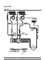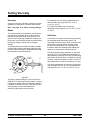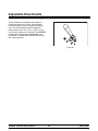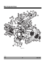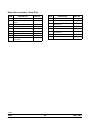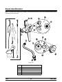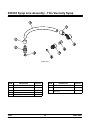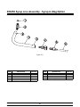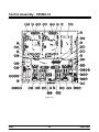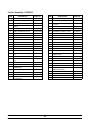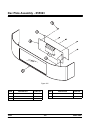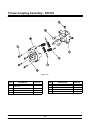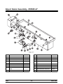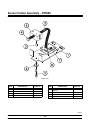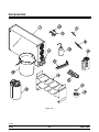
1
Model C602
Combination Shake /
Soft Serve Freezer
Service Manual
057888-S
6/24/04
Table of Contents
Section 1: Introduction . . . . . . . . . . . . . . . . . . . . . . . . . . . . . . . . . . . . . . . . . . . . . . . . . . . . . .
Safety . . . . . . . . . . . . . . . . . . . . . . . . . . . . . . . . . . . . . . . . . . . . . . . . . . . . . . . . . . . . . . . . . . .
Refrigerant . . . . . . . . . . . . . . . . . . . . . . . . . . . . . . . . . . . . . . . . . . . . . . . . . . . . . . . . . . . . . . .
Model C602 Specifications . . . . . . . . . . . . . . . . . . . . . . . . . . . . . . . . . . . . . . . . . . . . . . . . .
Installation Instructions . . . . . . . . . . . . . . . . . . . . . . . . . . . . . . . . . . . . . . . . . . . . . . . . . . . .
Section 2: Systems, Controls and Operations . . . . . . . . . . . . . . . . . . . . . . . . . . . . . . . .
Running Specifications . . . . . . . . . . . . . . . . . . . . . . . . . . . . . . . . . . . . . . . . . . . . . . . . . . . .
Refrigeration System Schematic . . . . . . . . . . . . . . . . . . . . . . . . . . . . . . . . . . . . . . . . . . . .
Control Panel Functions . . . . . . . . . . . . . . . . . . . . . . . . . . . . . . . . . . . . . . . . . . . . . . . . . . .
Freezer Lock-Out . . . . . . . . . . . . . . . . . . . . . . . . . . . . . . . . . . . . . . . . . . . . . . . . . . . . . . . . .
Service Menu . . . . . . . . . . . . . . . . . . . . . . . . . . . . . . . . . . . . . . . . . . . . . . . . . . . . . . . . . . . .
Heat Treatment Cycle . . . . . . . . . . . . . . . . . . . . . . . . . . . . . . . . . . . . . . . . . . . . . . . . . . . . .
Heat Treatment Graph . . . . . . . . . . . . . . . . . . . . . . . . . . . . . . . . . . . . . . . . . . . . . . . . . . . . .
Timers . . . . . . . . . . . . . . . . . . . . . . . . . . . . . . . . . . . . . . . . . . . . . . . . . . . . . . . . . . . . . . . . . . .
Glycol System . . . . . . . . . . . . . . . . . . . . . . . . . . . . . . . . . . . . . . . . . . . . . . . . . . . . . . . . . . . .
Glycol Path . . . . . . . . . . . . . . . . . . . . . . . . . . . . . . . . . . . . . . . . . . . . . . . . . . . . . . . . . . . . . .
Setting Viscosity . . . . . . . . . . . . . . . . . . . . . . . . . . . . . . . . . . . . . . . . . . . . . . . . . . . . . . . . . .
Portion Control (Shake) . . . . . . . . . . . . . . . . . . . . . . . . . . . . . . . . . . . . . . . . . . . . . . . . . . . .
Adjustable Draw Handle . . . . . . . . . . . . . . . . . . . . . . . . . . . . . . . . . . . . . . . . . . . . . . . . . . .
Control Overview . . . . . . . . . . . . . . . . . . . . . . . . . . . . . . . . . . . . . . . . . . . . . . . . . . . . . . . . .
Universal Control (UVC3) . . . . . . . . . . . . . . . . . . . . . . . . . . . . . . . . . . . . . . . . . . . . . . . . . .
Electrical System Modes of Operation Chart . . . . . . . . . . . . . . . . . . . . . . . . . . . . . . . . . .
Electrical System - L1 Power Path . . . . . . . . . . . . . . . . . . . . . . . . . . . . . . . . . . . . . . . . . .
Shake Draw Sequence Chart . . . . . . . . . . . . . . . . . . . . . . . . . . . . . . . . . . . . . . . . . . . . . . .
Shake Draw Solenoid Electrical Circuit . . . . . . . . . . . . . . . . . . . . . . . . . . . . . . . . . . . . . .
Shake Dispensing Alignment Procedure . . . . . . . . . . . . . . . . . . . . . . . . . . . . . . . . . . . . .
Syrup Delivery . . . . . . . . . . . . . . . . . . . . . . . . . . . . . . . . . . . . . . . . . . . . . . . . . . . . . . . . . . . .
Syrup Calibration . . . . . . . . . . . . . . . . . . . . . . . . . . . . . . . . . . . . . . . . . . . . . . . . . . . . . . . . .
Section 3: Troubleshooting . . . . . . . . . . . . . . . . . . . . . . . . . . . . . . . . . . . . . . . . . . . . . . . . .
General Troubleshooting Guide . . . . . . . . . . . . . . . . . . . . . . . . . . . . . . . . . . . . . . . . . . . . .
Air Mix Pump System Troubleshooting . . . . . . . . . . . . . . . . . . . . . . . . . . . . . . . . . . . . . . .
Peristaltic Syrup System Troubleshooting Guide . . . . . . . . . . . . . . . . . . . . . . . . . . . . . .
Shake Dispensing Mechanism Troubleshooting . . . . . . . . . . . . . . . . . . . . . . . . . . . . . . .
Shake Portion Control Troubleshooting . . . . . . . . . . . . . . . . . . . . . . . . . . . . . . . . . . . . . .
Bacteria Troubleshooting . . . . . . . . . . . . . . . . . . . . . . . . . . . . . . . . . . . . . . . . . . . . . . . . . .
Model C602
1
2
2
4
5
7
8
9
10
14
17
33
34
35
37
39
40
41
42
43
44
49
50
52
53
55
58
59
61
62
67
68
71
73
74
Table of Contents
Table of Contents - Page 2
Section 4: Parts . . . . . . . . . . . . . . . . . . . . . . . . . . . . . . . . . . . . . . . . . . . . . . . . . . . . . . . . . . . .
Parts Warranty Explanation . . . . . . . . . . . . . . . . . . . . . . . . . . . . . . . . . . . . . . . . . . . . . . . .
Main Exploded View . . . . . . . . . . . . . . . . . . . . . . . . . . . . . . . . . . . . . . . . . . . . . . . . . . . . . .
Operator Parts Identification . . . . . . . . . . . . . . . . . . . . . . . . . . . . . . . . . . . . . . . . . . . . . . . .
Front View . . . . . . . . . . . . . . . . . . . . . . . . . . . . . . . . . . . . . . . . . . . . . . . . . . . . . . . . . . . . . . .
Beater Door Assembly - Shake Side . . . . . . . . . . . . . . . . . . . . . . . . . . . . . . . . . . . . . . . .
Beater Door Assembly - Soft Serve Side . . . . . . . . . . . . . . . . . . . . . . . . . . . . . . . . . . . . .
Pump A. - Mix Simplified Shake - X57028-XX . . . . . . . . . . . . . . . . . . . . . . . . . . . . . . . .
Pump A. - Mix Simplified Soft Serve - X57029-XX . . . . . . . . . . . . . . . . . . . . . . . . . . . . .
Brush Identification . . . . . . . . . . . . . . . . . . . . . . . . . . . . . . . . . . . . . . . . . . . . . . . . . . . . . . . .
Syrup Cabinet View . . . . . . . . . . . . . . . . . . . . . . . . . . . . . . . . . . . . . . . . . . . . . . . . . . . . . . .
Syrup Pump & Tubes . . . . . . . . . . . . . . . . . . . . . . . . . . . . . . . . . . . . . . . . . . . . . . . . . . . . . .
X56652 Syrup Line Assembly - Triple Thick Shake Syrup . . . . . . . . . . . . . . . . . . . . . .
X59304 Syrup Line Assembly - Thin Viscosity Syrup . . . . . . . . . . . . . . . . . . . . . . . . . .
X58450 Syrup Line Assembly - Syrup-In-Bag Option . . . . . . . . . . . . . . . . . . . . . . . . . .
Control Assembly - X55966-33 . . . . . . . . . . . . . . . . . . . . . . . . . . . . . . . . . . . . . . . . . . . . .
Dec Plate Assembly - X55963 . . . . . . . . . . . . . . . . . . . . . . . . . . . . . . . . . . . . . . . . . . . . . .
Torque Coupling Assembly - X54722 . . . . . . . . . . . . . . . . . . . . . . . . . . . . . . . . . . . . . . . .
Glycol Heater Assembly - X55965-27 . . . . . . . . . . . . . . . . . . . . . . . . . . . . . . . . . . . . . . . .
Sensor Holder Assembly - X55980 . . . . . . . . . . . . . . . . . . . . . . . . . . . . . . . . . . . . . . . . . .
Accessories . . . . . . . . . . . . . . . . . . . . . . . . . . . . . . . . . . . . . . . . . . . . . . . . . . . . . . . . . . . . . .
Syrup Pump X53800-BRN/TAN . . . . . . . . . . . . . . . . . . . . . . . . . . . . . . . . . . . . . . . . . . . . .
Parts List . . . . . . . . . . . . . . . . . . . . . . . . . . . . . . . . . . . . . . . . . . . . . . . . . . . . . . . . . . . . . . . .
Wiring Diagrams . . . . . . . . . . . . . . . . . . . . . . . . . . . . . . . . . . . . . . . . . . . . . . . . . . . . . . . . . .
77
78
80
83
85
87
89
90
91
92
93
94
95
96
97
98
100
101
102
103
104
106
107
127
E April, 2004 Taylor
All rights reserved.
057888--S
The word Taylor and the Crown design
are registered trademarks in the United States
of America and certain other countries.
Table of Contents
Taylor Company
750 N. Blackhawk Blvd.
Rockton, IL 61072
Model C602
Section 1: Introduction
Model C602
S
Safety
S
Refrigerant
S
Specifications
S
Installation Instructions
1
Introduction
Safety
Refrigerant
______________________________
______________________________
We at Taylor Company, are committed to
manufacturing safe operating and serviceable
equipment. The many built-in safety features that
are part of all Taylor equipment are aimed at
protecting operators and trained service technicians
alike.
Taylor Company uses R404A refrigerant. This
refrigerant is generally considered non-toxic and
non-flammable; however, any gas under pressure is
potentially hazardous.
This manual is intended exclusively for Taylor
Company authorized service personnel.
NEVER fill any refrigerant cylinder
completely with liquid. Filling the cylinder to
approximately 80% will allow for normal expansion.
Stationary appliances which are not
equipped with a power cord and a plug or other
device to disconnect the appliance from the power
source must have an all-pole disconnecting device
with a contact gap of at least 3 mm installed in the
external installation.
Refrigerant liquid sprayed onto the skin may
cause serious damage to tissue. Keep eyes and skin
protected. If refrigerant burns should occur, flush
immediately with cold water. If burns are severe,
apply ice packs and contact a physician
immediately.
The Taylor Company reminds technicians to be
cautious of government laws regarding
refrigerant recovery, recycling, and reclaiming
systems. If you have any questions regarding
these laws, please contact the factory Service
Department.
This machine must be placed on a level
surface. Failure to comply may result in personal
injury or equipment damage.
DO NOT install the machine in an area
where a water jet could be used to clean or rinse the
freezer. Failure to follow this instruction may result in
serious electrical shock.
WARNING: R404A refrigerant used in conjunction
with polyolester oils is extremely moisture
absorbent. When opening a refrigeration system, the
maximum time the system is open must not exceed
15 minutes. Cap all open tubing to prevent humid air
or water from being absorbed by the oil.
DO NOT remove the door, beater, scraper
blades, drive shaft or air/mix pump unless all control
switches are in the OFF position. Failure to follow
this instruction may result in severe personal injury
from hazardous moving parts.
This machine is designed to operate indoors, under
normal ambient temperatures of 70°-75°F
(21°-24°C). The machine has successfully
performed in high ambient temperatures of 104°F
(40°C) at reduced capacities.
NOISE LEVEL: Airborne noise emission does not
exceed 70 dB(A) when measured at a distance of
1.0 meter from the surface of the machine and at a
height of 1.6 meters from the floor.
040608
Introduction
2
Model C602
Compressor Warranty Disclaimer
______________________________
It should be noted, that Taylor does not warrant the
refrigerant used in its equipment. For example, if the
refrigerant is lost during the course of ordinary
service to this machine, Taylor has no obligation to
either supply or provide its replacement either at
billable or unbillable terms. Taylor does have the
obligation to recommend a suitable replacement if
the original refrigerant is banned, obsoleted, or no
longer available during the five year warranty of the
compressor.
The Taylor Company will continue to monitor the
industry and test new alternates as they are being
developed. Should a new alternate prove, through
our testing, that it would be accepted as a drop-in
replacement, then the above disclaimer would
become null and void. To find out the current status
of an alternate refrigerant as it relates to your
compressor, call the local Taylor Distributor or the
Taylor Factory. Be prepared to provide the
model/serial number of the unit in question.
The refrigeration compressor(s) on this machine are
warranted for the term indicated on the warranty
card accompanying this machine. However, due to
the Montreal Protocol and the U.S. Clean Air Act
Amendments of 1990, many new refrigerants are
being tested and developed; thus seeking their way
into the service industry. Some of these new
refrigerants are being advertised as drop-in
replacements for numerous applications. It should
be noted that, in the event of ordinary service to this
machine’s refrigeration system, only the refrigerant
specified on the affixed data label should be used.
The unauthorized use of alternate refrigerants will
void your compressor warranty. It will be the owners’
responsibility to make this fact known to any
technicians they employ.
Model C602
3
Introduction
Model C602 Specifications
Freezing Cylinders
Electrical
Shake Side: One, 7 quart (6.6 liter)
Soft Serve: One, 3.4 quart (3.2 liter)
Mix Hopper
Standard is 208/230-60-3; however, other electrical
characteristics are available. Each unit requires
electrical service - Three Phase Maximum Fuse
Size: 40 A, Minimum Wire Ampacity: 36 A
Two, 20 quart (18.9 liter). Refrigerated to maintain
mix below 41°F (5°C).
Note: McDonald’s specifies Hubbell A460P9 plug
for 208-230/60-3 equipment.
Beater Motor
Air Cooled
Shake: 1.0 HP
Soft Serve: 1.5 HP
Clearance: A minimum of 3” (76 mm) is required
around all sides. Install the deflector provided to
prevent recirculation of warm air. Minimum air
clearances must be met to assure adequate air flow
for optimum performance.
Refrigeration System
Shake: 11,000 BTU/hr
Soft Serve: 9,500 BTU/hr
Dimensions
Refrigerant: R404A (BTU’s may vary depending on
compressor used.)
Width: 25-1/4” (641 mm) including cup/cone
dispenser: 32-3/8” (822 mm)
Height: 60-7/16” (1535 mm)
Depth: 38-7/8” (987 mm)
Floor Clearance: 4-3/4” (121 mm)
Main Compressor:
Air Cooled Units:
Shake: 54 oz (1,531 g) of R404A
Soft Serve: 46 oz (1,304 g) of R404A
Water Cooled Units:
Shake: 48 oz (1,361 g) of R404A
Soft Serve: 32 oz (907 g) of R404A
Approximate Weights
Net: 815 lbs. (369.7 kgs)
Crated: 1046 lbs. (474.5 kgs)
Volume: 66.5 cu ft (1.88 cu m)
Note: Specifications are subject to change. Check
the data label for proper charging specifications.
Figure 1
Introduction
4
Model C602
Installation Instructions
Beater Rotation
This machine must be placed on a level
surface. Failure to comply may result in personal
injury or equipment damage.
REMEMBER TO DISCONNECT ALL
POWER TO THE FREEZER! Failure to follow this
instruction may result in electrocution.
DO NOT install the machine in an area
where a water jet could be used to clean or rinse the
freezer. Failure to follow this instruction may result in
serious electrical shock.
Beater rotation = CLOCKWISE (when viewed from
the front of the machine).
Note: This machine is equipped with an interlock
circuit that prevents beater motor operation when
the freezer door is not installed.
Disconnect Switch
Stationary appliances which are not
equipped with a power cord and a plug or other
device to disconnect the appliance from the power
source must have an all-pole disconnecting device
with a contact gap of at least 3 mm installed in the
external installation.
1.
Remove the side panels.
2.
Place the power switch in the ON position.
3.
Select the WASH key on the control panel. This
activates the beater motor only.
CAUTION: Hazardous moving
components! Keep your hands clear when
operating the machine with the panels
removed. Failure to follow this instruction may
result in severe personal injury from hazardous
moving parts.
Air Cooled Units
These units require a minimum of 3” (76 mm) of air
clearance around all sides. Install the deflector
provided to prevent recirculation of warm air.
Minimum air clearances must be met to assure
adequate air flow for optimum performance.
4.
Check the rotation of the drive coupling located
on the output shaft of the gear reducer. The
coupling should be turning CLOCKWISE as
viewed from the front of the machine.
5.
Press the WASH key again to stop the beater
motor.
Gear Alignment and Rear Shell Bearing
1.
Make certain the drive shaft can easily slide in
and out of the female socket on the gear unit.
2.
If a drive shaft is binding, the gear unit could be
out of alignment (loose). Check the bolts on the
gear unit to be sure they are tight.
3.
If rotation is not correct, exchange any two incoming
power lines at the freezer main terminal box only
(splice box).
Inspect the rear shell bearing for tightness. Be
sure the locking tab has been folded over to
prevent the nut from loosening.
REMEMBER TO DISCONNECT ALL
POWER TO THE FREEZER! Failure to follow this
instruction may result in electrocution.
Note: If the gear unit is out of alignment, refer to
the General Service Manual.
Model C602
5
Introduction
Pump Motor Rotation
1.
Remove the air/mix pump assembly.
2.
Connect power to the freezer and place the
power switch in the ON position.
3.
Press the PUMP key on the control panel. This
will activate the pump motor only.
4.
Observe the pump ball crank. It should be
rotating counterclockwise.
Electrical Connections
Each freezer requires one power supply. Check the
data label on the freezer for fuse, circuit ampacity
and electrical specifications. Refer to the wiring
diagram, provided inside the control box, for proper
power connections.
In the United States, this equipment is intended to
be installed in accordance with the National
Electrical Code (NEC), ANSI/NFPA 70-1987. The
purpose of the NEC code is the practical
safeguarding of persons and property from hazards
arising from the use of electricity. This code contains
provisions considered necessary for safety.
Compliance therewith and proper maintenance will
result in an installation essentially free from hazard!
If rotation is not correct, refer to the wiring diagram
on the pump motor and re-wire accordingly.
In all other areas of the world, equipment should be
installed in accordance with the existing local codes.
Please contact your local authorities.
REMEMBER TO DISCONNECT ALL
POWER TO THE FREEZER! Failure to follow this
instruction may result in electrocution.
Stationary appliances which are not equipped with a
power cord and a plug or other device to disconnect
the appliance from the power source must have an
all-pole disconnecting device with a contact gap of at
least 3 mm installed in the external installation.
Introduction
6
Model C602
Section 2:
Systems, Controls and Operations
Model C602
S
Running Specifications
S
Refrigeration System Schematic
S
Control Panel Functions
S
Freezer Lock-Out
S
Service Menu
S
Heat Treatment Cycle
S
Heat Treatment Graph
S
Timers
S
Glycol System
S
Glycol Path
S
Setting Viscosity
S
Portion Control (Shake)
S
Adjustable Draw Handle
S
Control Overview
S
Universal Control (UVC3)
S
Electrical System Modes of Operation Chart
S
Electrical System - L1 Power Path
S
Shake Draw Sequence Chart
S
Shake Draw Solenoid Electrical Circuit
S
Shake Dispensing Alignment Procedure
S
Syrup Delivery
S
Syrup Calibration
7
Systems, Controls and Operations
Running Specifications
Pressures/Temperatures
Low Side (Suction)
The following are the Taylor Company
recommended settings for various components in
the Model C602. (See page 9 for the Refrigeration
System Schematic.)
Suction pressure equals expansion valve setting.
High Side (Discharge)
High side pressure varies for air cooled units,
depending on the ambient temperature.
Expansion Valve
Ambient Temperature
Normal Operating Head
Pressures
Soft Serve
Air Cooled: 20 - 22 psi. (138 - 152 kPa)
Water Cooled: 20 - 22 psi. (138 - 152 kPa)
for a normal product of 16_ - 18_F. (-8.8_to -7.7_C).
F
C
PSI
70_
21.1_
240 - 270
(1,655 - 1,862 kPa)
Shake
80_
26.7_
270 - 300
(1,862 - 2,069 kPa)
Air Cooled: 38 - 39 psi. (262 - 269 kPa)
Water Cooled: 38 - 39 psi. (262 - 269 kPa
for a normal product of 24_ - 26_F. (-4_C).
90_
32.2_
300 - 340
(2,069 - 2,344 kPa)
100_
37.8_
340 - 380
(2,344 - 2,620 kPa)
Note: Triple Thick Shake product temperature is
22_- 24_F. (-5_C).
Water Valve
Expansion Valve Adjustment
On a water cooled unit, the water valve should be
set to maintain a compressor head pressure of 255
psi. (1,758 kPa).
Connect your refrigerant gauge to the low side
access valve. Turn the access valve
counter-clockwise to open the valve.
Water Valve Adjustment
Adjust the pressure higher or lower by turning the
expansion valve adjustment screw. Clockwise turns
will raise the pressure and counterclockwise will
lower the pressure.
Note: Make this adjustment with mix in the cylinder
and the freezer in the AUTO mode. Be sure to allow
adequate time for pressure to stabilize.
Note: Make expansion valve adjustments with mix
in the freezing cylinder and the freezer in the AUTO
mode. Be sure to allow adequate time for the
pressure to stabilize.
Connect your refrigerant gauge to the high side
access valve. Turn the access valve counterclockwise to open the valve. Turning the adjustment
stem on the water valve clockwise will lower the
pressure.
Turn the access valve clockwise to close the valve.
Install and securely tighten the access valve caps
and the expansion valve cap.
Systems, Controls and Operations
Turn the access valve clockwise to close the valve.
Install and securely tighten the access valve caps.
8
Model C602
Refrigeration System Schematic
Figure 2
Model C602
9
Systems, Controls and Operations
Control Panel Functions
Figure 3
ITEM
1
2
3
4
5
6
7
8
9
DESCRIPTION
Keypad-Shake
Display-Vacuum
Fluorescent Menu (VFD)
Keypad-Menu (Entry/Exit)
Keypad-Soft Serve
Standby-Soft Serve
Standby-Shake
Keypad-Topping Heater
Display-LED Dual (Brush
Clean Countdown)
Keypad-Flavor Select
10
11
Switch-Power
Keypad-Calibrate Menu
12
Indicator Light-Mix Low
13
Indicator Light-Mix Out
Systems, Controls and Operations
FUNCTION
Used for selecting operating functions on the shake side of the machine.
Screen which displays menu options and notifies operator if a fault is
detected.
Used to select the Manager or Service Menu or to exit the Menu Display.
Used for selecting operating functions on the soft serve side of the
machine.
Indicates when the soft serve side is in the Standby mode.
Indicates when the shake side is in the Standby mode.
Used to activate the topping rail heaters.
Displays the number of days before brush cleaning is required.
Used for selecting the desired shake flavor to be dispensed. Also used
for opening and closing the draw valve when cleaning, sanitizing, and
priming the shake side.
When placed in the ON position, allows control panel operation.
Used to access the Calibrate Menu containing options for calibrating the
syrup dispensing rate or priming and flushing the syrup lines.
Illuminates when the mix hopper has a low supply of mix and should be
refilled as soon as possible.
Illuminates when the mix hopper has an insufficient supply of mix to
operate the freezer. The Auto mode will be locked out and the machine
will be placed in the Standby mode.
10
Model C602
Symbol Definitions
= CALIBRATE
To better communicate in the International arena,
the words on many of our operator keys have been
replaced by symbols to indicate their functions. Your
Taylor equipment is designed with these
International symbols.
= MENU DISPLAY
The following chart identifies the symbol definitions.
= AUTO
Power Switch
When placed in the ON position, the power switch
allows control panel operation.
= HEAT CYCLE
= WASH
Vacuum Fluorescent Display
= MIX PUMP
The vacuum fluorescent display (VFD) is located on
the front control panel. During normal operation the
display is blank. The display is used to show menu
options and notifies the operator if a fault is
detected. On International models, the display will
indicate the temperature of the mix in each hopper.
= STANDBY (SHAKE)
= STANDBY (SOFT SERVE)
= FLAVOR SELECTION
Indicator Lights
= MIX LOW
MIX LOW - When the MIX LOW symbol
is
illuminated, the mix hopper has a low supply of mix
and should be refilled as soon as possible.
= MIX OUT
symbol is
MIX OUT - When the MIX OUT
illuminated, the mix hopper has been almost
completely exhausted and has an insufficient supply
of mix to operate the freezer. At this time, the AUTO
mode is locked out and the freezer will be placed in
the STANDBY mode. To initiate the refrigeration
system, add mix to the mix hopper and touch the
= TOPPING HEATER-LEFT
= TOPPING HEATER-RIGHT
AUTO symbol . The freezer will automatically
begin operation.
Model C602
11
Systems, Controls and Operations
The SAFETY TIMEOUT screen will be displayed
with the alarm on, for 60 seconds or until any control
symbol is selected.
Heat Mode Symbol
When the HEAT MODE symbol
is illuminated,
the freezer is in the process of a heat cycle. The
heat mode symbol may be selected to start a heat
cycle following a freezer soft lock condition.
After the safety timeout has been completed and the
power switch is OFF, the following screen is
displayed. (See Figure 6.)
For some International models, the heat symbol can
be selected to manually start a heat cycle at any
time.
POWER SWITCH OFF
=-=-=-=-=-=-=UNIT CLEANED
Brush Clean Countdown - Displays the number of
days before the next brush cleaning is required.
When the display has counted down to “1”, the
machine must be disassembled and brush cleaned
within 24 hours.
Figure 6
Power Up
When the machine is powered the control system
will initialize to perform a system check. The screen
will display “INITIALIZING”. There will be four types
of data the system will check: LANGUAGE,
SYSTEM DATA, CONFIG DATA, and LOCKOUT
DATA.
Power Switch ON
When the power switch is placed in the ON position,
the control panel touch keys become operative. The
VFD will be either blank or indicate that the unit has
been cleaned. (See Figure 7.)
During the INITIALIZING... LANGUAGE screen, the
alarm will be on. If the system detects corrupt data
during INITIALIZING, the following display will alert
the operator that the control settings may have been
changed (See Figure 4.)
UNIT CLEANED
SERVICE REQ’D
NVRAM FAULT
RESET TO DEFAULTS
< PRESS TO CLEAR
Figure 7
Figure 4
Display for International Models Only:
Once the system has initialized, the number of days
remaining before the next required brush cleaning is
indicated on the control panel and the SAFETY
TIMEOUT screen is displayed with the alarm turned
on. (See Figure 5.)
Some International models will continuously display
the temperature of each mix hopper when the power
switch is in the ON position. (See Figure 8.)
HOPPERS
SAFETY TIMEOUT
ANY KEY ABORTS
21.1
UNIT CLEANED
Figure 5
Systems, Controls and Operations
21.0
Figure 8
12
Model C602
Heat Cycle
The HEAT symbols
on the control panel are
illuminated throughout the heat treatment cycle. Two
warning messages will be displayed on the screen.
“DO NOT DRAW” will be displayed when the mix
temperature is below 130°F (54.4°C). (See
Figure 9.)
L:
R:
DO NOT attempt to draw product or
disassemble the unit during the HEAT cycle. The
product is hot and under extreme pressure.
In the HEAT cycle, the mix temperature in the
hoppers and freezing cylinders must be raised to
151°F (66.1°C) within 90 minutes.
DO NOT DRAW
DO NOT DRAW
When the heating phase is complete, the freezer
goes into the holding phase of the cycle. The holding
phase will keep the temperature above 151°F
(66.1°C) for a minimum of 30 minutes.
Figure 9
When the temperature of the mix is above 130°F
(54.4°C) the screen will display a message
indicating that HOT PRODUCT is in the machine.
(See Figure 10.)
L:
R:
The final phase of the heat treatment cycle is the
cooling phase. The freezer must cool the mix below
41°F (5°C) within two hours.
When the entire heat cycle has been completed, the
HOT PRODUCT
HOT PRODUCT
will no longer be illuminated. The
HEAT symbols
machine will enter the STANDBY mode (STANDBY
and
illuminate). The machine can be
symbols
placed in AUTO or left in STANDBY.
Figure 10
Model C602
13
Systems, Controls and Operations
Freezer Lock-Out
Heat Cycle Failure Messages
will display the
Selecting the WASH symbol
following screen. (See Figure 12.)
To comply with health codes, heat treatment system
freezers must complete a heat treatment cycle
daily, and must be disassembled and brush cleaned
a minimum of every 14 days. Brush cleaning is the
normal disassembly and cleaning procedure found in
the Operator Manual. Failure to follow these
guidelines will cause the control to lock the freezer
out of the AUTO mode.
FREEZER LOCKED
Figure 12
2.
Always comply with local guidelines for the
maximum number of days allowed between brush
clean cycles. (See the Manager/Service Menu for
setting the Brush Clean interval, on page 21.)
If the Heat Treatment Cycle fails, the VFD will
display a failure message and return the freezer to
the STANDBY mode. A “lock” is defined as a special
STANDBY mode of operation which does not allow
the machine to operate in the AUTO mode.
There has been a thermistor failure (freezing
cylinder, hopper, or glycol) during the heat
treatment process. (See Figure 13.)
<
SYSTEM FAULT
FREEZER LOCKED
SERVICE REQ’D
PRESS TO CLEAR
Figure 13
Selecting the CALIBRATE symbol
will indicate
which thermistor caused the Hard Lock. (See
Figure 14.)
There are two types of freezer lock conditions that
can occur: Hard Lock or Soft Lock. A Hard Lock
requires the machine be disassembled and brush
cleaned. A Soft Lock can be corrected by either
disassembling and brush cleaning the machine, or
by starting another heat treatment cycle.
L: HOPPER THERM BAD
FREEZER LOCKED
Hard Lock: There are two causes of a hard lock
failure:
Figure 14
1.
If the machine has hard locked and an attempt is
made to enter AUTO, the machine will enter the
STANDBY mode and display the following message.
(See Figure 15.)
The brush clean timer has elapsed (maximum
setting of 14 days). (See Figure 11.)
BRUSH CLEAN TIMEOUT
FREEZER LOCKED
CLEANING REQ’D
WASH TO BRUSH CLEAN
FREEZER LOCKED
Figure 11
Systems, Controls and Operations
Figure 15
14
Model C602
To restore the message that identified the reason for
the hard lock, turn the power switch OFF for five
seconds and then return the power switch to the ON
position. The original message with the reason for
the Hard Lock will be displayed. The FAULT
DESCRIPTION can also be found in the Manager or
Service Menu (See page 22.)
Reasons For Soft Lock
Following are the variable messages for soft lock
failures that appear on the second line of the screen.
Power Switch Off
The FREEZER LOCKED message will remain on
the display until the brush clean requirements are
fulfilled. The freezer must be disassembled in order
to activate the five minute timer on the display
screen. Once the timer counts down to zero, the
lockout is cleared.
This soft lock will occur if the power switch is in the
OFF position and greater than 24 hours have
passed since the start of the 14 day timer, or the
start of the last successful Heat Treatment Cycle.
Soft Lock: If a heat treatment cycle has not been
initiated within the last 24 hours, a soft lock failure
will occur. A soft lock allows the operator to correct
the cause of the soft lock. The operator has the
option of either starting another heat cycle or brush
cleaning the machine. When a soft lock occurs, the
machine will go into the STANDBY mode. The
following message is displayed on the screen. The
reason for the soft lock is indicated on the second
line. (See Figure 16.)
Mix Out
This soft lock will occur if one or both sides has a
mix out condition and greater than 24 hours have
passed since the start of the 14 day timer or the
start of the last successful Heat Treatment Cycle.
Auto or Standby Off
This soft lock will occur if one or both sides is in the
OFF mode and greater than 24 hours have passed
since the start of the 14 day timer or the start of the
last successful Heat Treatment Cycle.
HEAT TREAT FAILURE
REASON
HEAT FOR HEAT CYCLE
WASH TO BRUSH CLEAN
No Heat Cycle Tried
Figure 16
No Heat Treatment Cycle was performed in the 24
hours after the start of the 14 day timer, or the start
of the last successful Heat Treatment Cycle. (AUTO
HEAT TIME was advanced,a power loss was
experienced at the time the cycle was to occur, or a
heat cycle failure not due to a thermistor failure.)
If the reason for the soft lock has been corrected,
selecting the HEAT symbol
initiates a Heat Cycle
immediately. Selecting the WASH symbol
when
the above message is displayed will hard lock the
machine and brush cleaning will be necessary.
Model C602
15
Systems, Controls and Operations
If the following screen appears, a soft lock has
occurred during the heat treatment cycle.
(See Figure 17.)
is selected to clear the
If the WASH symbol
lockout by brush cleaning the machine, the
FREEZER LOCKED message will remain on the
display until the brush clean requirements are
fulfilled. The freezer must be disassembled in order
to activate the five minute timer on the display
screen. Once the timer counts down to zero, the
lockout is cleared. (See Figure 20.)
HEAT TREAT FAILURE
FREEZER LOCKED
HEAT FOR HEAT CYCLE
WASH TO BRUSH CLEAN
Figure 17
A soft lock can also occur any time during operation
when the hopper or freezing cylinder temperature
rises above 59°F (15°C), or the temperature rises
and remains above 41°F(5°C) for more than four
hours. If a PRODUCT OVER TEMPERATURE
condition occurs during operation, the following
screen will appear. (See Figure 18.)
FREEZER LOCKED
Figure 20
To restore the message that identified the reason for
the soft lock, turn the power switch OFF for five
seconds, and then return the power switch to the
ON position. The original message with the reason
for the soft lock will be displayed. (See Figure 21.)
PRODUCT OVER TEMP
HEAT FOR HEAT CYCLE
WASH TO BRUSH CLEAN
HEAT TREAT FAILURE
REASON
HEAT FOR HEAT CYCLE
WASH TO BRUSH CLEAN
Figure 18
When one of these messages appears, automatic
freezer operation cannot take place until the freezer
is disassembled and brush cleaned, or has
completed a heat treatment cycle. Select the HEAT
symbol
Figure 21
to start a heat cycle, or select the WASH
The FAULT DESCRIPTION can also be found in the
Manager and Service Menus. (See page 22.)
symbol
to disassemble and brush clean the
machine.
Note: A record of Heat Cycle Data and Lock Out
History can be found in the Manager and Service
Menus. (See page 23.)
Once the freezer is unlocked by starting a heat
will illuminate
treatment cycle the HEAT symbol
and the following message will be displayed on the
screen. (See Figure 19.)
L: DO NOT DRAW
R: DO NOT DRAW
Figure 19
Systems, Controls and Operations
16
Model C602
Service Menu
The Service Menu option allows a trained service
technician to access and modify critical operating
parameters for the machine. All the menu screens
found in the Manager’s Menu are also included in
the Service Menu. To access the menu, touch the
center of the CONE symbol.
screen is displayed. The control keys for both sides
are only functional when the CURRENT
CONDITIONS screen is displayed.
Entering Access Code
With the ACCESS CODE screen on the display use
13117
the AUTO
or OPTIONAL FLAVOR
symbols
to set the first code number in the cursor position.
When the correct number is selected, touch the
CALIBRATION symbol
next number position.
to move the cursor to the
The access code for the Service Menu is 5231.
The access code for the Manager Menu is 8309.
(See Figure 23.)
ENTER ACCESS CODE
5231
_
Figure 22
The shake AUTO symbol
, the OPTIONAL
FLAVOR symbol
and the CONE symbol
will
be illuminated when the ACCESS CODE screen is
displayed.
Figure 23
In the Menu program, the shake side AUTO symbol
Continue to enter the proper access code numbers
until all four numbers are displayed, and then touch
, OPTIONAL FLAVOR symbol
CALIBRATION symbol
keys.
, and
. The Service Menu
the CALIBRATION symbol
list will display on the screen, provided the correct
access code is entered.
will function as menu
If an incorrect number is entered for the access
code, the display will exit the Menu program when
- increases the value above the cursor
AUTO
and used to scroll upward in text displays
the CALIBRATION symbol
Figure 24.)
- decreases the value
OPTIONAL FLAVOR
above the cursor and used to scroll downward in text
displays.
is selected. (See
13118
- advances the cursor position to
CALIBRATION
the right and is used to select menu options.
Note: You will not be able to dispense shakes while
accessing the Service Menu options, except when
the CURRENT CONDITIONS screen is displayed.
The soft serve side will continue operation in the
mode it was in when the Menu was selected.
However, the soft serve side control keys will not be
illuminated and are non-functional when a menu
Model C602
Figure 24
17
Systems, Controls and Operations
Service Menu Options
EXIT FROM MENU
Touch the AUTO symbol
Selecting “EXIT FROM MENU” will exit the Menu
and the return the control panel symbols to normal
operation.
or OPTIONAL FLAVOR
symbol
to move up or down through the Menu.
Select a Menu option by aligning the option with the
arrow on the left side of the screen, and then touch
SYRUP CALIBRATION
The SYRUP CALIBRATION option allows the
technician to access the CALIBRATION screen
selections from the Service menu. The same
functions found in the Calibration menu are
displayed on the screen when this menu option is
selected. (See Figure 25.)
. Exit the Menu
the CALIBRATION symbol
program by selecting EXIT FROM MENU or touch
the CONE symbol
.
The following menu options are listed in the Service
Menu:
Note: Options “EXIT FROM MENU” through
“CURRENT CONDITIONS” can also be accessed
through the Manager’s Menu.
>
UNFLAVORED DRAW
SYRUP CALIBRATION
SYRUP PRIME
EXIT
Figure 25
Note: The Unflavored Draw option will only appear
on the screen when the shake side is in the AUTO
mode.
EXIT FROM MENU
SYRUP CALIBRATION
VERIFY CALIBRATION
RESET DRAW COUNTER
SET CLOCK
AUTO HEAT TIME
AUTO START TIME
STANDBY MODE
BRUSH CLEAN CYCLE
MIX LEVEL AUDIBLE
FAULT DESCRIPTION
LOCKOUT HISTORY
HEAT CYCLE SUMMARY
HEAT CYCLE DATA
SYSTEM INFORMATION
CURRENT CONDITIONS
TEMPERATURE SCALE
STANDBY TEMPERATURE
HOPPER TEMPERATURE
GLYCOL TEMPERATURE
VISCOSITY SETTING
COMPRESSOR CYCLE TIME
COMPRESSOR ON DELAY
BEATER OFF DELAY
MIX PUMP OFF DELAY
WHITESPOT ADJUST
CAL SYRUP TIME
DRAW SAFETY TIME
EDIT UNIT ID
CALIBRATE PROXIMITY SWITCH
SELECT LANGUAGE
ABORT HEAT CYCLE
SYRUP MOTOR SETUP
See Syrup Calibration on page 59 for additional
information.
VERIFY CALIBRATION
The VERIFY CALIBRATION option is used to verify
that the amount of syrup dispensed is within the
proper specification. (See Figure 26.)
VERIFY CALIBRATION
Select a flavor
<- Press to clear
Figure 26
Remove the syrup valve from the dispensing door.
With the line fully primed with syrup, position the
syrup valve over the small chamber side of the
divided syrup cup, and then select the
corresponding favor selection. Syrup will flow into
the cup for 5 seconds (7 seconds for Triple Thick
Shake Syrup) and then automatically stop flowing.
Place the cup on a flat surface and check the
amount of syrup dispensed. If the level is not within
the correct specification, the flavor will need to be
recalibrated.
to exit the
Select the CALIBRATION symbol
VERIFY CALIBRATION screen and return to the
Menu list.
040617
Systems, Controls and Operations
18
Model C602
To change the date or time, select the SET CLOCK
RESET DRAW COUNTER
option in the menu. Touch the AUTO symbol
to
advance the arrow from Exit to Change, and then
The SERVING COUNTER screen is used to check
or reset the number of servings dispensed from the
machine. The SERVING COUNTER will
automatically reset to zero when the machine is
brush cleaned. (See Figure 27.)
touch the CALIBRATION symbol
Change option. (See Figure 30.)
to select the
SET CLOCK
08:00
04/02/2004
Change
> Exit
SERVINGS COUNTER
LEFT
RIGHT
0
0
> Next
Figure 30
Figure 27
Change the time by touching the AUTO
Reset the SERVING COUNTER by selecting the
CALIBRATION symbol
or
OPTIONAL FLAVOR symbol
with the cursor
under the hour position. Move the cursor to the
to advance to the next
minutes by selecting the CALIBRATION symbol
Once the correct minutes are entered, select the
screen. Select the AUTO symbol
to move the
arrow (>) to YES and select the CALIBRATION
.
to advance the cursor to
CALIBRATION symbol
the month. (See Figure 31.)
. The servings counter will reset to zero
symbol
and exit back to the Menu. (See Figure 28.)
SET CLOCK
08:00
04/02/2004
__
> Exit
RESET DRAW COUNTER
Yes
> No
Figure 31
Figure 28
Enter the correct month, day, and year. Then select
SET CLOCK
the CALIBRATION symbol
to advance to the
DAYLIGHT SAVING TIME screen. (See Figure 32.)
The SET CLOCK option allows the manager or
service technician to adjust the control clock date
and time. The date and time may only be changed
after the freezer has been manually cleaned but
before it has been placed in the AUTO or STANDBY
mode. The following message will be displayed if the
SET CLOCK option is selected when the machine is
not in a brush clean state. (See Figure 29.)
DAYLIGHT SAVING TIME
ENABLED
> Enable
Disable
Figure 32
SET CLOCK
08:00
04/02/2004
NO CHANGES ALLOWED
> Press Any Key
The Daylight Saving Time feature, when enabled,
will automatically adjust the control clock for daylight
saving time. To Disable the Daylight Saving Time
to move the
feature, select the AUTO symbol
arrow to Disable. Then touch the CALIBRATION
Figure 29
Model C602
symbol
19
to save the new setting.
Systems, Controls and Operations
AUTO HEAT TIME
Select the AUTO symbol
FLAVOR symbol
to increase or decrease the
hour to the desired setting. Then move the cursor to
the minutes position by selecting the CALIBRATION
The AUTO HEAT TIME screen allows the manager
or service technician to set the time of day in which
the heat treatment cycle will start. (See Figure 33.)
symbol
. Adjust the setting for minutes, then
select the CALIBRATION symbol
to save the
setting and return to the AUTO HEAT TIME screen.
Select the CALIBRATION symbol
screen and return to the Menu.
AUTO HEAT TIME
00:00
Change
> Exit
The AUTO START TIME option allows the manager
or service technician to set the time of day at which
the machine automatically enters the AUTO mode
from the STANDBY mode. The machine must be in
the STANDBY mode without a freezer lock condition
in order to AUTO start at the programmable time.
The AUTO START TIME can be disabled and will
require starting the AUTO mode manually. (See
Figure 35.)
Note: Do not advance the Auto Heat Time setting
except on the day the unit is brush cleaned.
Increasing the time between heat cycles will cause
the machine to soft lock if the start of the cycle does
not begin within 24 hours from the start of the
previous heat treatment cycle.
AUTO START TIME
DISABLED
Enable
> Disable
To set the AUTO HEAT TIME select the AUTO
to move the arrow to Change. Then
Figure 35
select the CALIBRATION symbol
. The screen
will display the time with the cursor under the hour
position. (See Figure 34.)
Enable the AUTO START TIME by selecting the
AUTO symbol
to move the arrow up to Enable.
Select the CALIBRATION symbol
the next screen. (See Figure 36.)
AUTO HEAT TIME
00:00
__
to advance to
AUTO START TIME
00:00
Change
> Exit
Figure 34
Systems, Controls and Operations
to exit the
AUTO START TIME
Figure 33
symbol
or the OPTIONAL
Figure 36
20
Model C602
Program the AUTO START TIME by selecting the
AUTO symbol
BRUSH CLEAN CYCLE
to move the arrow to Change.
Select the CALIBRATION symbol
the next screen. (See Figure 37.)
to advance to
The BRUSH CLEAN CYCLE option allows the
manager or service technician to select the
maximum number of days between brush cleaning
the machine. The brush clean cycle may only be
changed after the freezer has been manually
cleaned but before it has been placed in the AUTO
or STANDBY mode.
AUTO START TIME
00:00
__
Figure 37
The following message will be displayed if the
BRUSH CLEAN CYCLE option is selected when the
machine is not in a brush clean state.
(See Figure 39.)
Program the AUTO START TIME by increasing
(AUTO symbol
) or decreasing (OPTIONAL
FLAVOR symbol
) the hour setting above the
cursor. Select the CALIBRATION symbol
to
advance the cursor and program the minutes
setting.
BRUSH CLEAN CYCLE
TIME 14 DAYS
NO CHANGES ALLOWED
Press Any Key
to return to the
Select the CALIBRATION symbol
previous screen with the new time setting displayed.
Select the CALIBRATION symbol
screen and return to the Menu.
to exit the
Figure 39
STANDBY MODE
The Standby option is used only on models which
have the control panel Standby keys disabled.
Change the number of days between brush clean
intervals by selecting the AUTO symbol
to
decrease the days or the OPTIONAL FLAVOR
The STANDBY option is used to manually place the
left or right side in the standby mode during long, no
draw periods. Select the STANDBY screen from the
symbol
the CALIBRATION symbol
to save the setting
and exit back to the Menu. The number of days
displayed on the brush clean counter will change to
the new setting. (See Figure 40.)
to move the
Menu. Select the AUTO symbol
arrow up to the left (shake) or right (soft serve) side.
Select the CALIBRATION symbol
Standby for the selected side.
to increase the number of days. Select
to activate
Repeat the steps to activate Standby on the
remaining side. (See Figure 38.)
BRUSH CLEAN CYCLE
TIME 14 DAYS
STANDBY MODE
LEFT
RIGHT
> Exit
Figure 40
Figure 38
Always comply with local guidelines on the number
of days allowed between brush clean cycles.
Discontinue Standby operation for either side by
exiting the Menu and select the AUTO mode.
Model C602
21
Systems, Controls and Operations
MIX LEVEL AUDIBLE
Listed below are the variable messages which will
appear, along with an explanation for the corrective
action.
The MIX LEVEL AUDIBLE option, when enabled,
will alert the operator with an audible tone when
there is mix low or mix out condition. The following
screen is displayed upon selecting this option. (See
Figure 41.)
NO FAULT FOUND - There was no fault found in
the freezer. Nothing will appear on the screen after
this variable message appears.
BEATER OVERLOAD - Press the beater reset
button firmly for the side of the freezer with the fault.
MIX LEVEL AUDIBLE
ENABLED
> Enable
Disable
HPCO COMPRESSOR - Place the power switch in
the OFF position. Wait 5 minutes for the machine to
cool. Place the power switch in the ON position and
restart each side in AUTO.
HOPPER THERMISTOR BAD - Place the power
switch in the OFF position. Replace the bad probe.
Figure 41
BARREL THERMISTOR BAD - Place the power
switch in the OFF position. Replace the bad probe.
Disable the audible tone feature by selecting the
OPTIONAL FLAVOR symbol
to move the arrow
to DISABLE. Select the CALIBRATION symbol
to save the new setting and return to the Menu. The
control panel icons for Mix Low and Mix Out will
illuminate as the mix level drops in the hopper but
the audible tone will be disabled.
GLYCOL THERMISTOR BAD - Place the power
switch in the OFF position. Replace the bad probe.
LOCKOUT HISTORY
The LOCKOUT HISTORY screen displays a history
of the last 40 soft locks, hard locks, brush clean
dates, or aborted heat cycles. Page numbers are
indicated in the upper right hand corner. Page 1
always contains the most recent failure. (See
Figure 43.)
FAULT DESCRIPTION
The FAULT DESCRIPTION display will indicate if
there is a fault with the freezer and the side of the
freezer where the fault occurred. When no faults are
detected the following screen will be displayed. (See
Figure 42.)
LOCKOUT HISTORY
00/00/00
00:00
REASON
> Exit
FAULT DESCRIPTION
L: NO FAULT FOUND
R: NO FAULT FOUND
Figure 43
The second line of the screen displays the date and
time a failure occurs. The third line indicates the
reason for a failure, or will indicate if a successful
brush cleaning has occurred. Some failures occur
with multiple reasons. When this occurs, a page will
be generated for each reason.
Figure 42
Select the CALIBRATION symbol
to display the
next fault found or return to the Menu if no other
Select the AUTO symbol
faults exist. Selecting the CALIBRATION symbol
any time faults are displayed will clear the faults if
corrected, upon returning to the Menu screen.
Systems, Controls and Operations
2
or OPTIONAL FLAVOR
symbol
to advance forward or backward to view
each screen.
22
Model C602
Listed below are the variable messages that may
appear.
Faults Occurring While in AUTO Mode
(L/R) HPR>41F (5C) AFTER 4 HR - The mix
temperature in the left or right hopper was above
41°F (5°C) more than four hours.
Faults Occurring While Entering a Heat Treatment
Cycle
(L/R) BRL>41F (5C) AFTER 4 HR - The mix
temperature in the left or right barrel was above
41°F (5°C) more than four hours.
POWER SWITCH OFF - The power switch is OFF.
AUTO OR STBY OFF - The control was not in
AUTO or STANDBY.
(L/R) HPR>41F (5C) AFTER PF - The mix
temperature in the left or right hopper was above
41°F (5°C) more than four hours following a power
failure.
MIX OUT FAILURE - A mix out condition was
present.
NO HEAT CYCLE TRIED - The Auto Heat Time
was set to attempt a heat cycle more than 24 hours
after the last successful heat cycle.
(L/R) BRL>41F (5C) AFTER PF - The mix
temperature in the left or right barrel was above
41°F (5°C) more than four hours following a power
failure.
Faults Occurring While in Heat Mode
(L/R) HPR>59F (15C) - The mix temperature in the
left or right hopper exceeded 59°F (15°C).
HEAT MODE FAILURE - The maximum allowable
heat mode time exceeded 90 minutes.
(L/R) BRL>59F (15C) - The mix temperature in the
left or right barrel exceeded 59°F (15°C).
COOL MODE FAILURE - The maximum allowable
cool mode time exceeded 120 minutes.
HEAT CYCLE SUMMARY
The HEAT CYCLE SUMMARY screen displays the
hours since the last heat cycle, the hours since the
product temperature was above 150°F (65.6°C), and
the number of heat cycles completed since the last
brush clean date. (See Figure 44.)
TOTAL TIME FAILURE - The maximum allowable
total heat treatment time exceeded 4 hours.
BRUSH CLEAN TIMEOUT - The total days in
operation exceeded the brush clean cycle setting.
POWER SWITCH OFF - The power switch was
turned OFF during the heat cycle.
HEAT CYCLE SUMMARY
HRS SINCE HC
0
HRS SINCE 150.0
0
HRS SINCE BC
0
POWER FAIL IN H/C - A power failure occurred
during the heat treatment cycle.
(L/R) MIX LOW FAILURE - The mix level in the
(left/right) Hopper is too low for a successful heat
cycle.
Figure 44
HEAT CYCLE DATA
The HEAT CYCLE DATA screen contains a record
of up to 366 heat treatment cycles. The most recent
heat cycle data will be shown first. Each heat cycle
record or page has two screens. The first screen
displays the month and day of the heat cycle, the
start time and end time, and which side of the
machine underwent the heat treatment cycle; L for
Left side, R for Right side, and B for both sides. Line
3 displays the total time in each heat cycle phase.
Line 4 displays the glycol temperature at the
completion of the heat cycle and the page number.
(L/R) BEATER OVLD H/C - The overload tripped for
the (left/right) side beater motor.
(L/R) BRL THERM FAIL - The thermistor sensor for
the (left/right) side barrel failed.
(L/R) HOPPER THERM FAIL - The thermistor
sensor for the (left/right) side hopper failed.
(L/R) HPCO H/C - The (left/right) side high pressure
switch opened during the heat treatment cycle.
Model C602
23
Systems, Controls and Operations
Listed below are variable failure code messages
which could appear on line 2.
Select the AUTO symbol
to advance forward
through the data pages. Select the OPTIONAL
FLAVOR symbol
(See Figure 45.)
to reverse the page direction.
00/00 00:00 00:00
HEAT OVER COOL
00:00 00:00 00:00
TEMP AT END 0.0
HT
Heat Time Too Long
Mix temperature did not rise above 151°F
(66.1°C) in less than 90 minutes.
CL Cool Time Too Long
Mix temperature in the hopper and freezing
cylinder did not fall below 41°F (5°C) in less
than 120 minutes.
TT Total Time Too Long
The heat treatment cycle must be completed
in no more than 4 hours.
MO Mix Out Condition
A mix out condition was detected at the start
or during the heat cycle.
ML Mix Low Condition
The Heat Phase or Cool Phase time was
exceeded and a mix low condition was
present.
BO Beater Overload Condition
A beater overload occurred during the heat
cycle.
HO High Pressure Cut-Out Condition
A high pressure cut-out condition occurred
during the heat cycle.
PF Power Failure
A power failure caused the Heat Phase,
Cool Phase, or Total Cycle Time to exceed
the maximum allowed time. If a power failure
occurs, but the heat treatment cycle does
not fail, an asterisk(*) will appear on the third
line of the display.
PS Power Switch OFF
The power switch was placed into the OFF
position during the heat cycle.
TH Thermistor Switch OFF
A thermistor probe has failed.
RC Record Cleared
Data has not been written to the page or
cleared due to corrupt data.
OP Operator Abort
Indicates the heat cycle was aborted in the
OPERATOR ABORT option in the service
menu.
PD Product Door Not in Place
A product door is not in place or is loose.
B
RC
*
1
Figure 45
The second screen will have the same page number
and display the temperature recorded in each
hopper, barrel, and the temperature of the glycol
when the heat cycle was terminated. The left hopper
and barrel temperature is displayed on line 2 and the
right side temperatures on are line 3. The time in the
last phase of heat cycle, whether successful or
failed, is displayed on line 4.
Select the AUTO symbol
to advance to the next
page or the OPTIONAL FLAVOR symbol
the previous page. (See Figure 46.)
to view
HOPPER BARREL GLYCOL
000.0
000.0
000.0
000.0
000.0
PHASE TIME: 00:00
1
Figure 46
Heat Cycle Failure codes will display on the first
screen on line 2 if a failure occurred.
(See Figure 47.)
HOPPER BARREL GLYCOL
000.0
000.0
000.0 HT
000.0
000.0
PHASE TIME: 00:00
1
Figure 47
Systems, Controls and Operations
24
Model C602
SYSTEM INFORMATION
VISC
HOPPER
BARREL
GLYCOL
The SYSTEM INFORMATION is displayed on three
separate screens. The first screen contains the
control and software version installed in the
machine. (See Figure 48.)
0
41.0
41.0
0.0
41.0
41.0
41.0
Figure 51
SOFTWARE VERSION
SERIES C600 CONTROL UVC
VERSION 1.02
> Next
CURRENT CONDITIONS is the only Menu screen
that will return the left and right side control panel
keys to normal operation. The Menu keys will not be
illuminated when this option is selected so shakes
can be dispensed and all panel touch keys are fully
functional. Use this screen when you wish to remain
in the Menu and dispense a shake. Exit the
CURRENT CONDITIONS screen and return to the
Figure 48
to advance to
Select the CALIBRATION symbol
the next system information screen containing the
software language version. (See Figure 27.)
.
Menu by selecting the CALIBRATION symbol
Language
v1.12r00 English 568
>
Note: All screens from this point forward can only
be accessed through the service menu.
Next
TEMPERATURE SCALE
Figure 49
to advance to
Select the CALIBRATION symbol
the third system information screen containing the
model bill of material and machine serial number.
The TEMPERATURE SCALE option allows the
service technician to choose the scale in which the
machine will display all temperatures. (See
Figure 52.)
again will
Selecting the CALIBRATION symbol
return to the Menu list. (See Figure 50)
B.O.M. C600000000
S/N
K0000000
>
TEMPERATURE SCALE
FAHRENHEIT
> Fahrenheit
Celsius
Next
Figure 50
Figure 52
CURRENT CONDITIONS
The CURRENT CONDITIONS screen provides the
viscosity readings for the product when the side is
running and hopper and barrel temperatures for both
sides of the machine. The left column displays the
readings for the shake side and the right column
displays the soft serve side readings. The bottom
line in the display indicates the current glycol
temperature. (See Figure 51.)
To change the scale setting, use the AUTO
symbol
or OPTIONAL FLAVOR symbol
to
move the cursor along side of the desired
temperature scale then touch the CALIBRATION
to save the selection and return to the
symbol
service menu.
040608
Model C602
25
Systems, Controls and Operations
STANDBY TEMPERATURE
HOPPER TEMPERATURE
The STANDBY TEMPERATURE option allows the
service technician to adjust the freezing cylinder
temperature in the Standby mode. In Standby, the
machine will cycle the compressor (and beater) on if
the temperature of the product in the freezing
cylinder rises above the setpoint. The compressor
will cycle off when the temperature of the product in
the freezing cylinder drops 4°F (2.2°C) or more
below the set point. (See Figure 53.)
The HOPPER TEMPERATURE menu allows the
service technician to adjust the hopper temperature
by which the glycol pump and the left and right
glycol solenoids are controlled when the machine is
operating in AUTO or STANDBY modes.
Hopper cooling is activated when the mix
temperature rises above the set point temperature.
When the temperature drops 2°F (1°C) below the
set point the hopper cooling is discontinued. (See
Figure 55.)
STANDBY TEMP
L CUT IN AT : 30.5
CURRENT : 30.5
> Next
HOPPER TEMP
L CUT IN AT : 39.0
CURRENT : 39.0
> Next
Figure 53
Figure 55
Adjust the temperature setting using the AUTO
symbol
Adjust the temperature setting using the AUTO
to increase the temperature or
symbol
OPTIONAL FLAVOR symbol
to decrease the
temperature. Save the setting by selecting the
OPTIONAL FLAVOR symbol
to decrease the
temperature. Save the setting by selecting the
to advance to the next
CALIBRATION symbol
screen for the right side freezing cylinder Standby
temperature setting. (See Figure 54.)
to advance to the next
CALIBRATION symbol
screen for the right side Hopper temperature setting.
(See Figure 56.)
STANDBY TEMP
R CUT IN AT : 30.5
CURRENT : 30.5
> Next
HOPPER TEMP
R CUT IN AT : 39.0
CURRENT : 39.0
> Next
Figure 54
Figure 56
Select the CALIBRATION symbol
to save the
setting and return to the Service Menu.
Systems, Controls and Operations
to increase the temperature or
to save the
Select the CALIBRATION symbol
setting and return to the Service Menu.
26
Model C602
GLYCOL TEMPERATURE
VISCOSITY SETTING
The GLYCOL TEMPERATURE allows the Service
Technician to adjust the glycol temperature used to
control the glycol heater in the HEAT and HOLD
phases of the Heat Treatment Cycle.
The viscosity setting option allows the service
technician to adjust the viscosity at which the
compressor cycles off during the AUTO mode of
operation.
When the glycol temperature falls 6°F (3.3°C) or
more below the set point, the glycol heater is
activated. When the glycol temperature rises above
the set point, the heater is de-activated. The factory
glycol temperature setting is 178°F (81°C). (See
Figure 57.)
to move the cursor up
Select the AUTO symbol
to the left or right side viscosity setting. (See
Figure 59.)
VISCOSITY SETTING
LEFT
RIGHT
> Exit
GLYCOL TEMPS
HEATING : 178.0
CURRENT : 41.0
> Next
Figure 59
Figure 57
Shake Viscosity Setting (Left):
Adjust the temperature setting using the AUTO
symbol
to increase the temperature or
Select the AUTO symbol
OPTIONAL FLAVOR symbol
to decrease the
temperature. Save the setting by selecting the
to increase the viscosity
setting or the OPTIONAL FLAVOR symbol
decrease the setting. (See Figure 60.)
to advance to the next
CALIBRATION symbol
screen for the right Glycol temperature setting in the
HOLDING phase. (See Figure 58.)
to
VISCOSITY SETTING
LEFT = 4000HD
CURRENT = 0
GLYCOL TEMPS
HOLDING : 177.0
CURRENT : 41.0
> Next
Figure 60
Figure 58
The GLYCOL HOLDING TEMPERATURE set point
controls the glycol heater in the HOLDING phase of
the Heat Treatment Cycle. When the glycol
temperature is 6°F (3.3°C) or more below the set
point, the glycol heater is activated. When the glycol
temperature rises above the set point, the heater is
de-activated. The factory setting for the glycol
holding temperature is 177°F (81°C).
Note: A Hedlund (HD) is a Taylor factory defined
unit of measure representing the relative product
viscosity (thickness). Product in the shake machines
is normally set at a viscosity ranging from 4,000 to
7,500 HD’s to accomplish a neutral frozen product
temperature around 23° - 26°F (-5 to -3.3°C).
While the beater motor is on, the current viscosity
indicated on the display is updated continually.
When the beater motor is off, this value is zero.
Adjust the temperature setting using the AUTO
symbol
to increase the temperature or
OPTIONAL FLAVOR symbol
to decrease the
temperature. Select the CALIBRATION symbol
to save the setting and return to the Service Menu.
Model C602
to save the
Select the CALIBRATION symbol
setting and return the Service Menu.
27
Systems, Controls and Operations
Soft Serve Viscosity Setting (Right):
Advance to the next screen for the right side setting
or return to the service menu by selecting the
Enter the Viscosity option and select the AUTO
CALIBRATION symbol
.(See Figure 63.)
symbol
to move the cursor up to the right side
viscosity setting and select the CALIBRATION
symbol
. (See Figure 61.)
COMP CYCLE TIME
R CYCLE TIME : 10 MIN
VISCOSITY SETTING
RIGHT = 2.8 AMPS
CURRENT = 0.0
Figure 63
COMPRESSOR ON DELAY
Figure 61
Select the AUTO symbol
to increase the viscosity
The COMPRESSOR ON DELAY allows the service
technician to adjust the time the compressor will
delay starting when the unit is in the AUTO mode.
The range for the delay time is 2 seconds to 10
seconds and is adjustable in one-second intervals.
setting or the OPTIONAL FLAVOR symbol
to
decrease the setting. Select the CALIBRATION
to save the setting and return to the
symbol
screen to the Viscosity Setting menu.
Use the AUTO symbol
Soft serve viscosity is measured by monitoring the
amperage load of the beater motor. While the beater
motor is on, the viscosity or amperage is indicated
on the display. When the beater motor is off, this
value is zero.
FLAVOR symbol
to adjust the setting. The
recommended setting is 5 seconds for shake and 2
seconds for soft serve applications.
The Left Compressor On delay screen is displayed
first (See Figure 64.)
COMPRESSOR CYCLE TIME
The COMPRESSOR CYCLE TIME option allows the
service technician to set the time that the
compressor will cycle on in the AUTO mode when
product is not dispensed from the machine.
Compressor Cycle Times range from 5 – 15 minutes
for shake and soft serve applications and is
adjustable in one-minute intervals. Use the AUTO
COMP ON DELAY
LEFT : 5 SECONDS
or the OPTIONAL FLAVOR symbol
to
symbol
adjust the setting. The recommended cycle times
are 5 minutes for shake and 10 minutes for soft
serve.
Figure 64
Advance to the next screen for the right side setting
or return to the service menu by selecting the
CALIBRATION symbol
The Left Compressor Cycle Time is displayed first.
(See Figure 62.)
. (See Figure 65.)
COMP ON DELAY
RIGHT : 2 SECONDS
COMP CYCLE TIME
L CYCLE TIME : 5 MIN
Figure 62
Systems, Controls and Operations
or the OPTIONAL
Figure 65
28
Model C602
BEATER OFF DELAY
MIX PUMP OFF DELAY
RIGHT : 10 SECONDS
The BEATER OFF DELAY allows the service
technician to set the time the beater motor continues
to run after the compressor has cycled off. The
range for the delay time is 0 seconds to 10 seconds
and is adjustable in one-second intervals. Use the
AUTO symbol
or the OPTIONAL FLAVOR
Figure 68
symbol
to adjust the setting. The recommended
setting is 0 seconds for shake and soft serve
applications.
Select the CALIBRATION symbol
Service Menu.
The Left Beater OFF Delay screen is displayed first
(See Figure 66.)
to return to the
WHITE SPOT ADJUST
BEATER OFF DELAY
LEFT : 0 SECONDS
This option allows the service technician to set the
White Spot Adjustment for each syrup flavor. (See
Figure 69.)
Figure 66
Advance to the next screen for the right side setting
or return to the service menu by selecting the
CALIBRATION symbol
WHITESPOT ADJUST
TIME : 0.2 SEC
CHOCOLATE
. See Figure 67.)
BEATER OFF DELAY
RIGHT : 0 SECONDS
Figure 69
Figure 67
to increase the
Select the AUTO symbol
whitespot setting or the OPTIONAL FLAVOR
MIX PUMP OFF DELAY
symbol
The MIX PUMP OFF DELAY allows the service
technician to set the amount of time the mix pump
runs after the draw valve has closed (switch open).
This adjustment is for the soft serve mix pump only.
The recommended White Spot Setting for standard
shakes is 0.2 seconds. The recommended setting
for Triple Thick Shakes is 0.4 seconds.
The range is for the Pump Off Delay is 0 – 30
seconds and is adjustable in 1- second intervals.
Use the AUTO symbol
or the OPTIONAL
FLAVOR symbol
to adjust the setting. The
recommended setting is 10 seconds. (See
Figure 68.)
Model C602
to decrease the setting.
to save the
Select the CALIBRATION symbol
setting and advance to the Whitespot Setting for the
next flavor.
29
Systems, Controls and Operations
CAL SYRUP TIME
to save the setting and
CALIBRATION symbol
return to the Service Menu.
This option allows the service technician to adjust
the Calibrate Syrup Time which determines the flow
rate of the syrup.
EDIT UNIT ID
This option allows the service technician to enter the
factory Bill of Material (B.O.M.) code used to
assemble the machine, the freezer Serial Number
and the Store Identification Number. This
information must be programmed in the service
menu in order to view the information in the
SYSTEM INFORMATION screens. (See Figures 72,
73 & 74.)
Example: 1 oz.(28 g) syrup dispensed in 5 seconds.
The recommended Cal Syrup Time for standard
shakes is 5.0 seconds and is 7.0 seconds for Triple
Thick Shakes.
The following screen is displayed by selecting this
option: (See Figure 70.)
ENTER FREEZER BOM
C600000000
_
CAL SYRUP TIME
TIME : 5.0 SEC
Figure 72
Figure 70
Select the AUTO symbol
Select the AUTO symbol
to increase the time
OPTIONAL FLAVOR symbol
setting or the OPTIONAL FLAVOR symbol
to
decrease the setting. Select the CALIBRATION
to decrease the
value. Select the CALIBRATION symbol
to move
the cursor to the right and advance to the serial
number screen.
to save the setting and return to the
symbol
Service Menu.
DRAW SAFETY TIME
ENTER FREEZER SN
K0000000
_
This option allows the service technician to adjust
the Draw Safety Time used for closing the shake
draw valve in the AUTO Mode if the fill level is not
detected by the portion control sensor. The Draw
Safety Time should be set approximately 5 seconds
longer than the amount of time it takes to fill the
largest serving size.
Figure 73
Enter the serial number from the unit’s data label in
the same manner as the BOM, then select the
The following screen is displayed by selecting this
option. (See Figure 71.)
CALIBRATION symbol
to save the setting and
advance to the store identification screen.
DRAW SAFETY TIME
TIME : 11 SEC
ENTER STORE ID
00000
_
Figure 71
Figure 74
Enter the store number, then select the
to increase the Draw
Press the AUTO symbol
Safety Time setting or the OPTIONAL FLAVOR
symbol
to increase the value or
CALIBRATION symbol
to save the setting and
return to the Service Menu.
to decrease the setting. Select the
040608
Systems, Controls and Operations
30
Model C602
CALIBRATE PROXIMITY SWITCH
SELECT LANGUAGE
The SELECT LANGUAGE option allows the service
technician to select the language that will display on
the fluorescent display. Several language options
are available.
This option allows the service technicians to adjust
the mounting of the proximity switch. This procedure
must be performed while the machine is fully
assembled and properly primed. In addition, the
product temperature must be above 32°F (0°C) If
the temperature is below 32°F (0°C), the Temp.
Error screen will be displayed. (See Figure 75.)
Use the OPTIONAL FLAVOR symbol
symbol
or AUTO
to move the arrow to the desired
language then touch the CALIBRATION symbol
to save the selection. (See Figure 77.)
>
CAL PROXIMITY SW
ERROR TEMP MUST BE
GREATER THAN 32.0 F
> Exit
ENGLISH
ESPANOL
DANSK
FRANCIAS
Figure 77
Figure 75
ABORT HEAT CYCLE
This option allows the service technician to abort the
Heat Treatment Cycle if the machine is operating in
a heat cycle. The screen below will be displayed
upon selecting this option. Select the AUTO symbol
to move the arrow to “YES”, and then select the
When the barrel temperature is above 32°F (0°C)
the Cal Proximity screen will be displayed and the
shake side beater motor with be activated. (See
Figure 76.)
CALIBRATION symbol
to abort the heat cycle
and to return to the Service Menu. (See Figure 78.)
ABORT HEAT CYCLE
CAL PROXIMITY SW
RAW MIX 0
>
>
Exit
Yes
No
Figure 78
SYRUP MOTOR SETUP
Figure 76
The Syrup Motor Setup option allows the service
technician to adjust the running speed for each
syrup pump motor in the calibration mode and the
reverse time for the pump motor.
When the “CAL PROXIMITY SW” message is
displayed, adjusting the distance between the
proximity probe and the torque coupling will increase
or decrease the raw viscosity displayed. When the
raw viscosity is between 1000–1500, an audible tone
will sound at regular intervals. The target setting is
the middle of the audible tone range. Upon
completion of the calibrating procedures, lock the
switch down. Verify that the viscosity setting is
correct after the switch is locked. Selecting the
The proper syrup motor setting should be set to
gradually fill the calibration cup. If the syrup motor
setting is too fast the syrup will fill the cup too fast to
accurately stop the flow at the proper level.
The recommended setting for the syrup motor is 85
for thin viscosity shake syrup. For thick viscosity
syrup, the syrup motor setting may need to be set
higher (100 - 160) if the flow rate is too slow or the
amount of syrup measured in the Verification Mode
is not within the specified range.
will return to the Service
CALIBRATION symbol
Menu screen and discontinue beater motor
operation.
Model C602
31
Systems, Controls and Operations
The following screen appears when the Syrup Motor
Setup option is selected. (See Figure 79.)
If the reverse time setting is too short, pressure
remaining in the line may cause syrup to seep past
the duckbill valve after the shake is dispensed.
When this occurs, the flavoring will carry-over to the
next serving.
MOTOR SPEED SETUP
85
CHOCOLATE
If the reverse time setting is too long an air pocket
may form in the syrup line connected to the freezer
door. An air pocket in the line will delay syrup
blending with the frozen mix causing unflavored
product to be dispensed in the bottom of the cup.
Figure 79
Select the AUTO symbol
to increase the syrup
motor setting or the OPTIONAL FLAVOR symbol
to decrease the setting. Select the CALIBRATION
Select the AUTO symbol
symbol
to advance to the next screen.
time setting or the OPTIONAL FLAVOR symbol
to decrease the setting. Select the CALIBRATION
The second screen in the Syrup Motor Setup option
allows the service technician to adjust the reverse
time for the syrup pump motor. (See Figure 80.)
symbol
to advance to the motor speed setting
screen for the next flavor.
to increase the reverse
Enter the settings for the remaining flavors in the
same manner, then select the CALIBRATION
SYRUP MOTOR SETUP
TIME: 0.25 SEC
CHOCOLATE
symbol
to return to the Service Menu.
Note: To save the Syrup Motor Setup settings you
must advance through the screens for each flavor by
selecting the CALIBRATION symbol
. Exiting the
menu option by any other manner will not save the
new settings.
Figure 80
Each peristaltic pump motor must reverse the syrup
flow momentarily when the flow is stopped in order
to eliminate the pressure in the line and close the
duckbill syrup valve. The reverse time setting for
most thin viscosity syrups is 0.25 seconds. Thick
viscosity syrup may require a slightly longer reverse
time setting (0.26 – 0.32).
Examples: (Triple Thick Shake Settings)
FLAVOR
Chocolate
Strawberry
Vanilla
Optional
SPEED
160
140
85
100
REVERSE TIME
0.28
0.26
0.25
0.25
Systems, Controls and Operations
- 0.32
- 0.30
- 0.28
- 0.28
32
Model C602
Heat Treatment Cycle
The function of the Heat Treatment Cycle is to raise
the temperature of the mix in the freezing cylinder(s)
and hopper(s) high enough and quickly enough to
destroy bacteria. When this has been accomplished,
the temperatures must then be returned to a
temperature low enough and quickly enough to
retard spoilage.
The Hold Phase
During the HOLD phase, the temperature of the
product is “held” over 151.5_F (66_C) for a minimum
of 30 minutes to ensure the destruction of all harmful
bacteria in the product.
The Hold Phase Timer “times out” 30 minutes as
long as all freezing cylinder and hopper
temperatures remain above 151.5_F (66_C) for the
duration of the HOLD phase.
The Heat Treatment Cycle must be successfully
completed at least once every 24 hours or the
freezer will automatically lock itself in the STANDBY
mode.
The Heat Soak Timer prevents the HOLD phase
from entering the next COOL phase of the cycle until
the 30 minutes is satisfied and until the total time of
the HEAT and HOLD cycles combined is greater
than 115 minutes.
Single freezing cylinder operation is now available.
The software keeps track of the freezing cylinder(s)
“in use”. Therefore, the Heat Treatment Cycle can
now be performed on only one side, if the other side
has not been placed in AUTO or STANDBY since
the unit was last brush cleaned.
The Cool Phase
The Heat Treatment Cycle may be started
automatically according to the AUTO HEAT CYCLE
TIME.
During the COOL phase, the product in the freezing
cylinder and the hopper are lowered to 41_F (5_C)
or less. The unit must complete this phase in less
than 120 minutes.
IMPORTANT: The freezer must be operating in
either the STANDBY or AUTO mode before a Heat
Treatment Cycle can be started.
The COOL Phase Timer measures the maximum
allowable time the unit can remain in the COOL
phase. If the timer exceeds 120 minutes, the unit will
lock-out.
There are three phases in a Heat Treatment Cycle:
Heat, Hold and Cool.
During this phase, the temperatures of the product
in the freezing cylinder and hopper are raised over
151.5_F (66_C) in 90 minutes or less.
The Heat Cycle TT (Total Time) Timer “times out”
the maximum allowable time the unit can remain in
the Heat Treatment Cycle (4 hours). If the timer
exceeds four hours, the unit will lock-out. This timer
is a combination of the HEAT, HOLD, and COOL
Phase Times.
The Heat Phase Timer “times out” the maximum
allowable amount of time the unit can remain in the
HEAT phase of the Heat Treatment Cycle. If the
timer exceeds 90 minutes, the unit will lock-out.
When the entire Heat Treatment Cycle has been
completed, the normal display will appear, indicating
that the machine is operating in the STANDBY
mode.
The Heat Phase
Model C602
33
Systems, Controls and Operations
Heat Treatment Graph
During the HEAT and HOLD phases, the glycol is
heated by the use of a glycol heater. During the
COOL phase, the glycol and freezing cylinder
product are refrigerated by the use of the machine’s
main refrigeration system.
Once the HEAT Phase is complete, it is necessary
to complete the Heat Soak Timer. From the time the
Heat Phase is started, 115 minutes must transpire
before the cool phase may enter. Due to the
implementation of the Heat Soak Timer, the Heat
Cycle Data Screen will now refer to the HOLD phase
as the “OVER” phase.
At the start of the HEAT phase the glycol heater
begins to overcome the cold freezing cylinder
temperature and the glycol temperature raises
slowly to 178_F (81_C).
While in the COOL phase, the beater motor and the
main refrigeration system operate continuously until
the machine first cycles off. For the remainder of the
COOL phase, the beater motor and compressor
operate from a timed cycle. The timed cycle allows
the beater motor to stop for two minutes and then
run for six seconds. During the six seconds that the
beater motor is on, if the viscosity is below setpoint,
the compressor is turned on. When viscosity is
satisfied, the compressor and the beater are turned
off. The timed cycle continues in this manner until
the COOL phase is complete.
The purpose of the HEAT phase is to raise the
product temperature above 150_F (65_C) within 90
minutes. To satisfy the control system, the product
must actually reach 151.5_F (66_C). This
requirement ensures that the 150_F (65_C)
requirement has been met. Health laws require
these parameters to be 150_F (65_C) in 90 minutes;
however, the actual amount of time the freezer takes
to accomplish this requirement is closer to 60
minutes.
Figure 81
Systems, Controls and Operations
34
Model C602
Timers
Two Minute Stir Cycle
Mix Pump Timer
Shake - The mix pump will run for 10 seconds
anytime the unit is placed in the AUTO mode, but
not from STANDBY.
If either side of the machine is in the STANDBY
mode, the beater motor for that side will turn on for
six seconds every two minutes.
Soft Serve - The mix pump will run for 30 seconds
anytime the unit is placed in the AUTO mode.
If any hopper is above the cut-in temperature, the
beater stir cycle timer is activated.
Mix Draw Timer
(Soft Serve Application Only)
During the AUTO mode, the mix pump will run for 5 30 seconds every time product is drawn from the
machine. The factory setting is 10 seconds.
Soft Serve - If the machine is in the HEAT mode,
this two minute stir cycle will continue until the
freezing cylinder temperature rises above 135_F
(57_C). If the machine is in the AUTO mode or the
COOL phase of the Heat Treatment Cycle, and the
hopper is calling for refrigeration, the beater motor
and compressor will continue to run until the
viscosity setpoint has been reached.
Draw Safety Timer
(Shake Application Only)
During the AUTO mode, if the pyroelectric sensor
has not detected the product level, the safety timer
will terminate the draw. The draw safety timer is
adjustable from 3 - 60 seconds. The recommended
setting is five seconds longer than the time required
to dispense the largest serving size (International =
11 seconds, Triple Thick Shake = 24 seconds).
Shake - If the machine is in the AUTO mode and
the hopper is calling for refrigeration, the beater
motor will run once every two minutes. If the
freezing cylinder product viscosity has been satisfied
during this beater run time, the beater motor will turn
off. Otherwise, the compressor will also turn on and
run until the freezing cylinder product viscosity has
been satisfied. During the Heat Treatment Cycle the
beater motor runs continuously until viscosity is
satisfied in the Cool Phase after which the beater
motor will run as in the AUTO mode to cool the
hopper.
Brush Clean Countdown
The Brush Clean Countdown displays on the control
panel. It counts the number of days before the next
brush cleaning is required. When the display has
counted down to “1”, the following message will
appear on the VFD screen. (See Figure 82.) The
machine must be disassembled and brush cleaned
within 24 hours.
BRUSH CLEAN ON MM/DD
Glycol Pump Timer
Figure 82
If either side of the machine is operating in the
AUTO mode, and the hopper requires refrigeration,
the glycol pump will operate one minute, discontinue
for two minutes, then operate again for one minute.
This pattern continues until hopper refrigeration is no
longer required.
Model C602
24 Hour Last Heat Cycle Event
If the machine runs longer than 24 hours without a
successful Heat Treatment Cycle, the machine will
soft lock.
35
Systems, Controls and Operations
14 Day Timer
Cool Phase Timer
If the machine runs longer than 14 days without a
successful brush cleaning, the machine will hard
lock.
The Cool Phase Timer times out the maximum
allowable time the unit can remain in the COOL
phase of the Heat Treatment Cycle (120 minutes). If
the timer exceeds 120 minutes, the unit will lock out.
Note: This timer is adjustable from 2 to 14 days.
Heat Phase Timer
Safety Timeout
The Heat Phase Timer times out the maximum
allowable time the unit can be in the Heat Phase of
the Heat Treatment Cycle (90 minutes). If the timer
exceeds 90 minutes, the unit will lock-out.
Once power is applied to the unit, a 60 second timer
places the unit in an “IDLE” state. The tone is turned
on in 0.5 second intervals, and a “Safety Timeout”
message appears on the LCD. This timer can be
aborted by pressing any key.
Hold Phase Timer
This timer assures that product in the freezing
cylinder and the hopper are held above 150_F
(65_C) for a minimum of 30 continuous minutes.
Brush Clean Timer
Heat Soak Timer
This timer times out 5 minutes when all conditions
for a successful brush cleaning are met.
The Heat Soak Timer prevents the HOLD phase
from entering the COOL phase until the HOLD
phase requirements are met and the total time of the
HEAT and HOLD phases is greater than 115
minutes.
Systems, Controls and Operations
a. Mix Low/Mix Out condition
b. Hopper and barrel temperatures are above 60°F
(15.6°C).
c. Both freezer doors were removed concurrently.
36
Model C602
Glycol System
The following information describes the glycol
system. For further understanding, see the Glycol
Path diagram at the end of this chapter.
The Heat Treatment Cycle
During the heating phase the heater is activated. For
shake application, beater agitation will continue until
the compressor cycles off. For soft serve
application, the beater will agitate for six seconds
every two minutes until the freezing cylinder product
rises above 135_F (57_C).
The glycol system serves two purposes. During the
STANDBY and AUTO modes, the glycol is used to
cool the mix hoppers. During the HEAT mode, the
glycol is used to heat the mix in the hopper(s) and
freezing cylinder(s).
During the HEAT phase, all refrigeration is
cancelled, and the glycol will heat the freezing
cylinder(s) and the hopper(s) to the set
temperatures.
Glycol is a heat transfer medium made up of 50%
ethylene glycol and 50% distilled water.
Note: It is factory recommended to drain, flush and
re-supply a fresh glycol mixture on a two-year
maintenance schedule.
WARNING: Ethylene glycol is very
harmful to your health. Swallowing glycol is
fatal. Refer to M.S.D.S. Guidelines.
Note: If the glycol is purchased from the factory, it
is pre-mixed and ready to use. Otherwise, glycol
should be mixed with distilled water in a ratio of 50%
glycol and 50% distilled water.
Standby and Auto
During a refrigeration mode, the freezing cylinders
are cooled using refrigerant, and the product is
controlled by viscosity during the AUTO mode and
by temperature during the STANDBY mode.
Installing the Glycol Mixture
The hoppers are cooled in the following manner:
Step 1
Attach a hose (capable of depressing the shraeder
valve) to the 1/4” flare fitting located beneath the
accumulator tank. Remove the cap from the
accumulator and place the opposite end of the hose
into the accumulator tank.
When a hopper temperature reaches the cut-in
point, the glycol pump, solenoid valve, and beater
stir cycle are all activated.
The glycol lines go (in order) through the heater,
through the solenoid valve, around the freezing
cylinder, and then to the hopper. In other words, the
glycol is cooled directly by the freezing cylinder walls
and is then pumped to the hoppers to cool the mix.
Each hopper has one thermistor probe and can
function independently.
Step 2
Using a pair of pliers, squeeze the tube located
between the access fitting and the tube that leads to
the bottom of the glycol accumulator tank.
Step 3
Fill the accumulator tank 2/3 full.
Note: The heater is OFF during refrigeration
modes.
Step 4
Remove the necessary panels to expose the shake
interface board. Locate the test pins marked, “W2,
W3, W4, and W5”. Place a two pin jumper on the
test pins marked “W4”. The jumper will activate the
glycol pump and open the glycol solenoids (if
applicable). The glycol existing in the accumulator
will be pumped through the glycol system.
In each hopper, there is an agitator paddle which is
used to distribute the heat or cold evenly throughout
the mix so the mix does not freeze or burn on the
sides of the hopper. It runs continuously when the
freezer is in the AUTO, STANDBY or HEAT mode.
The agitator is driven by a motor and belt(s).
Model C602
37
Systems, Controls and Operations
Step 5
Monitor the level of glycol mixture in the tank and to
be sure all air pockets are removed, continue to add
more as necessary to maintain a 2/3 full level. Allow
the unit to operate for a short period of time. Once
the service hose starts to empty glycol back into the
accumulator tank, the system is properly filled.
Remove the jumper from the pins marked, “W4”.
Release the pliers.
Draining the Glycol Mixture
Step 1
Attach a service hose (capable of depressing the
shraeder valve) to the 1/4” access fitting. Allow the
opposite end of the hose to rest in an empty bucket.
Step 2
Using a pair of pliers, squeeze the tube located
between the access fitting and the tube leading to
the bottom of the glycol accumulator tank.
Step 6
Remove the service hose and replace the cap on
the 1/4” flare fitting. Replace the accumulator tank
cap.
Step 3
Remove the cap from the top of the accumulator
tank. The glycol will begin to flow into the bucket.
Step 7
Check for glycol mixture leaks.
Step 4
Remove the necessary panels to expose the shake
interface board. Locate the test pins marked, “W2,
W3, W4, and W5”. Place a two pin jumper on the
test pins marked, “W4”.
Replenishing the Glycol Mixture
Note: If the accumulator tank is empty, follow the
steps outlined in “Installing the Glycol Mixture”. If the
unit needs replenishing, complete the following
steps:
Step 5
Once the glycol mixture stops flowing into the
bucket, replace the cap on the glycol accumulator
tank.
Step 1
Remove the cap from the glycol accumulator tank.
Step 6
Disconnect the outlet line from the glycol pump.
Blow air or nitrogen through the outlet line from the
glycol pump. This procedure will fully drain the
system.
Step 2
Replenish the glycol mixture until the tank is 2/3 full.
Step 7
Once the system is fully drained, remove the service
hose and replace the access cap. Replace the outlet
line of the glycol pump to proper position. Remove
the pliers.
Step 3
Replace the cap on the accumulator.
Step 4
Check for glycol mixture leaks.
Figure 83
Systems, Controls and Operations
38
Model C602
Glycol Path
(Rear View)
Figure 84
Model C602
39
Systems, Controls and Operations
Setting Viscosity
For standard units, the serving temperature of a
flavored shake may range from 24_F to 26_F
(-4.4_C to -3.3_C).
Viscosity
Viscosity is the term used when referring to product
appearance, temperature, thickness and firmness.
For Triple Thick Shake units, the serving
temperature may range from 22_F to 24_F (-5.6_C
to -4.4_C)
Note: See page 27 to adjust viscosity settings.
Shake
The shake viscosity is measured by monitoring the
gap opening of the beater drive coupling which is
mounted on the output shaft of the gear unit. The
gear unit turns the spring loaded drive coupling. As
the product in the freezing cylinder becomes thicker,
the springs collapse, and the size of the gaps
change.
Soft Serve
The soft serve viscosity is measured by monitoring
the amperage load of the beater motor. The
amperage load of the beater motor is low when the
product in the freezing cylinder is liquid. As the
product freezes (thickens), the amperage load
increases. When the amperage load reaches the
setpoint, the refrigeration cycle discontinues.
As the gaps narrow, the Hedlunds (HD’s) increase.
As the product thickens (becomes colder) the HD’s
increase. After achieving a pre-adjusted HD setting,
the refrigeration cycle discontinues.
The factory default setting (setpoint) for soft serve
viscosity is 2.8 A. The amperage measurement is
determined by monitoring the L1 leg of power being
delivered to the beater motor. To adjust the serving
viscosity, it may be necessary to raise or lower the
amperage setpoint. Adjust in increases of 0.1 amp.
The serving temperature of soft serve product may
vary throughout the day. The serving temperature
may range from 16_F to 19_F (-8.8_C to -7.2_C).
Figure 85
The factory default setting for cycle off viscosity is
4000 HD’s. To adjust the serving viscosity, it may be
necessary to raise or lower the HD setting. Adjust in
increases of 100 HD’s at a time. Note: Be sure that
the syrups are correctly calibrated before
determining the proper serving viscosity.
Systems, Controls and Operations
40
Model C602
Portion Control (Shake)
The portion control sensor, located in the cup
bracket, is a pyro-electric sensor which responds to
temperature changes of any kind. When the draw
valve is opened (during the AUTO mode) and the
product level in the cup reaches the sensor, it will
recognize a temperature change. The control board
then automatically closes the draw valve.
At Pyro Sensor Board:
Portion Control Operation
Pin 2 - BLACK: This is the DC GROUND
connection.
Step 1
Verify that the shake personality board is properly
connected to the J3 (RED header):
Pin 1 - WHITE: This is the “sense” output of the
sensor.
The interface board receives 16 VAC from the
transformer and converts it to 12 VDC for the
personality board.
Pin 3 = GREEN: This is the 2.5 VDC reference
output of the sensor.
Auto Mode
Pin 4 = RED: This is the +12 VDC power supply for
the sensor.
If the sensor does not detect the product filling the
cup, the control board will automatically close the
draw valve after the Draw Safety Time has elapsed.
(See Draw Safety Time, page 30.)
Step 2
Verify that the wiring harness is properly connected
on J2:
Heat Mode
Pin 1 = 12 VDC
During the heat mode, the flavor keys will not open
the draw valve.
Pin 2 = This is the cup-full signal. It is normally less
than .2 VDC when a cup-full is not sensed, and
makes a momentary 5 VDC pulse when a cup-full is
sensed.
Portion Control Troubleshooting
At Personality Board:
Pin 5 = GROUND
Step 1
Verify that the shake personality board is properly
connected to the interface board.
Step 2
Verify J3 (RED header) connections:
Pin 3 = WHITE: This is the cup-full signal that goes
to the UVC through the interface board. It is
normally less than .2 VDC when a cup-full is not
sensed, and makes a momentary 5 VDC pulse when
a cup-full is sensed.
Pin 2 = BLACK: This is the DC GROUND
connection.
Pin 4 = RED: This is the +12 VDC power supply
from the interface board.
Model C602
41
Systems, Controls and Operations
Adjustable Draw Handle
This unit features an adjustable draw handle to
provide the best portion control, giving a better,
consistent quality to your product and controlling
costs. The draw handle should be adjusted to
provide a flow rate of 5 to 7-1/2 oz. (142 to 213 g.)
of product by weight per 10 seconds. To INCREASE
the flow rate, turn the screw CLOCKWISE, and
COUNTER- CLOCKWISE to DECREASE the flow
rate. (See Figure 86.)
Figure 86
Systems, Controls and Operations
42
Model C602
Control Overview
Figure 87
Model C602
43
Systems, Controls and Operations
Universal Control (UVC3)
ITEM
DESCRIPTION
FUNCTION
1
LED
When board is powered, LED flashes ON (0.5 sec.) and OFF (0.5 sec.).
2
5 VDC Power Supply
Supplies power to UVC3 Board (Range: 4.75 - 5.25 VDC)
3
USB Cable Connection
Communication to Control Panel Interface Board.
4
JP2 Pins
See table on page 45.
5
JP3 Pins
See table on page 45.
6
JP1 Pins
See table on page 45.
7
EPROM Chip
PLCC Chip-C602 Software Version Number.
8
RAM Chip
Stores program settings from menu in memory.
9
Audible Tone Device
Not activated on Model C602 (See table on page 45.)
Systems, Controls and Operations
44
Model C602
Note: For installations with low voltage supply
(210V or less) it may be necessary to wire the 16
VAC transformer on the low voltage tap. Low
voltage supplied to the interface board, in turn
reduces the voltage supplied to the UVC3 board and
may cause intermittent power failure tripping or the
control panel keys do not function when the machine
is powered.
Universal Control (UVC3)
The Universal control is the command center for the
machine. The software program, including multiple
language selections, resides in the EPROM chip.
The settings in the menus are saved in the RAM
chip. Removing and reinstalling the RAM chip will
restore the factory default settings in the menus.
The RAM chip must be inserted with the notch
towards the side of the socket with the notch.
The UVC3 communicates with the control panel
interface board through a USB Cable.
There are three sets of pins on the UVC3 board.
Refer to the following chart to identify their function.
Power is supplied to the 5 VDC terminal on the
UVC3 board from the interface board. The operating
voltage range for the control is 4.75 – 5.25 VDC.
JUMPER
Note: Use Part No. 040084-001 CONNECTORPROGRAMING SHUNT to jumper pins.
UVC3 PINS
FUNCTION
Jumper installed -- normal applications using refrigerated mix.
JP1
JP2
Pins 1 & 2
No jumper installed -- general market configuration using non--refrigerated mix.
Ignores hopper temperature lockout parameters to allow adding non--refrigerated
mix into the hopper.
Pins 3 & 4
No jumper -- Not used (for future development)
Pins 1 & 2
Domestic configuration -- jumper installed. Hopper temperature not displayed
on screen. Heat symbol keys are only active when a lockout condition has
occurred. Standby keys are disabled.
International configuration -- no jumper. Hopper temperature is displayed on
screen. Manual heat cycle starts by selecting HEAT symbol. Standby keys are
functional.
Pins 3 & 4
No jumper -- Not used (for future development)
Pins 1 & 2
Jumper installed -- enables audible device located on UVC3 control. Disabled (no
jumper) in models that have an audible device on the control panel board.
Pins 3 & 4
No jumper -- Not used (for future development)
JP3
040608
Model C602
45
Systems, Controls and Operations
UVC3 EPROM Chip
RAM Chip
When installing an EPROM chip with a new program
version it is recommended to clear the memory in
the RAM chip before installing the EPROM chip.
(See Figure 89 for RAM chip location.)
The EPROM is inserted into a socket on the UVC3
board. The angled corner on the chip identifies the
correct position for installation. A PLCC type
extraction tool is needed to remove the chip from the
socket. (See Figure 88.)
Figure 89
To clear the memory, briefly remove the RAM chip
from the socket. Be careful not to bend the pins. To
reinstall the chip, align the notch on the chip with the
notch end of the socket. Partially insert all the pins
on one side of the chip into the socket and then all
of the pins on the other side. Press the chip firmly
into the socket and check to insure all the pins are in
place.
Figure 88
Note: Attempting to remove the EPROM from the
socket without using the recommended extraction
tool may damage the control board.
EPROM Chip Replacement
1.
Insert the extraction tool pins in the two slots in
chip socket. Gently squeeze the tool to raise
the chip from the socket. For installation, align
the angled corner of the chip and socket and
insert the chip until it is fully inserted.
2.
Reinstall the control box cover and rear panel
and restore the power to the machine.
3.
You must first select the language to be
displayed on the screen. (See Figure 90.)
It is recommended to record the program settings in
the Service Menu before replacing the EPROM chip.
You must be properly grounded during chip
installations to prevent possible damage to the chip
from electrical discharge. The use of a grounding
strap is recommended.
>
WARNING: Place the power switch in
the OFF position and unplug the machine from
the power outlet before attempting the chip
replacement. Failure to follow this instruction may
result in electrocution.
English
Espanol
Dansk
Francais
Figure 90
040608
Systems, Controls and Operations
46
Model C602
4.
During the program initialization, (Language,
System Data, Config Data, Lockout Data) the
RESET TO DEFAULTS message will display
on the screen. (See Figure 91.)
>
7.
SERVICE REQUIRED
NVRAM FAULT
RESET TO DEFAULTS
PRESS TO CLEAR
Place the Power switch to ON, clear the two
information screens that appear, and the UNIT
CLEANED message will be displayed. (See
Figures 94, 95, and 96.)
Reset to Defaults
<-- Press to Clear
Figure 91
5.
Figure 94
Clearing the Defaults message will initiate the
Safety Timeout screen. (See Figure 92.)
Lockout CRC Error
SAFETY TIMEOUT
ANY KEY ABORTS
<-- Press to Clear
Figure 95
Figure 92
6.
After 60 seconds or selecting a key to abort the
Safety Timeout the POWER SWITCH OFF
message will appear on the screen. (See
Figure 93.)
Unit Cleaned
Power Switch OFF
_______________
_______________
Unit Cleaned
Figure 96
8.
Figure 93
Immediately access the Service Menu and
enter the proper program settings to complete
the chip installation.
040608
Model C602
47
Systems, Controls and Operations
Interface Boards
Control Panel Interface Board
Both interface boards are the same for the shake
and soft serve side. Ribbon cables provide the
communication path between the UVC3 and the
interface boards.
The Control Panel Interface Board (Dec Plate PCB)
is fastened to the back of the tempered glass panel
and communicates with the UVC3 through a USB
cable.
The control panel has two 5 VDC power leads
supplied to the board. One connection supplies
power to operate the touch sensors and LED’s and
the other 5 VDC connection provides power to
communicate with the UVC3 control.
A 16 VAC transformer supplies the power for the
interface boards at Terminals A and B. Each board
has a 5 VDC output terminal block. Line voltage is
connected to the interface boards (L1 and L2) to
operate components in the machine on command.
The Vacuum Fluorescent Display (VFD) plugs into a
socket on the interface board. The potentiometer
dial at the top of the board is non-functional. The
VFD does not require a contrast adjustment.
There are four sets of pins (W2,W3,W4,W5) on
each interface board. The pins on the soft serve
board are inactive in the Model C602. The pins on
the shake interface board function as follows:
Pins labeled W1 on the face of the Control Panel
Interface Board must have a jumper installed to
enable the audible tone when a key is selected. (W1
is located next to the audible tone device, below the
5 VDC connectors.)
W2 Installing a jumper resets the Brush Clean
date when both sides are in the OFF mode.
W3 If the machine is in the AUTO mode,
installing a jumper will simulate the viscosity
setpoint.
The interface board must have the insulator installed
to shield the circuitry on the back of the board. The
metal rectifier guard must be installed to shield the
interface board from electrical noise.
W4 Installing a jumper forces the start of the
glycol pump and both left and right glycol
solenoid are energized.
W5 If a jumper is present the real time clock can
be changed in any mode.
Motor Speed Control
The motor speed control is powered by 5 VDC and
receives data bit information through a 10 pin ribbon
cable. The speed control transmits a modulated
signal to the syrup motor, therefore the voltage
cannot be accurately measured with a meter.
Personality Boards
A Personality Board plugs into the interface board.
The shake proximity sensor (torque coupling sensor)
and the portion control pyro-electric board harness
are connected to the shake personality board. The
soft serve personality board monitors the amperage
in one leg of power supplied to the beater motor.
Systems, Controls and Operations
The syrup pump motors run at maximum speed in
the prime mode.
The UVC3 Control calculates the motor speed
setting in the syrup calibration mode and sends the
information to the speed control.
48
Model C602
Electrical System Modes of Operation Chart
COMPONENT
HEAT
Heat
Hold
Compressor
Beater Motor
X
X
Fan
STANDBY
WASH
AUTO
PRIME
Cool
X
X
X
X
X
X
X
X
X
X
Spinner Motor (Shake Only)
X
Air/Mix Pump Motor
X
Syrup Pump
X
Glycol Heater
X
X
Agitator
X
X
X
X
X
Left Glycol Solenoid
X
X
X
X
X
Right Glycol Solenoid
X
X
X
X
X
Glycol Pump
X
X
X
X
X
X
Shake Draw Solenoid
Model C602
PUMP
49
X
X
X
X
Systems, Controls and Operations
Electrical System - L1 Power Path
Power Cord Plugged In / Power Switch
in the OFF Position
Power Switch On / Mode Select: AUTO
With L1 power supplied to the L1 terminal on the
interface board, power is then given to terminal J6
and directed through the following pins:
L1 power from the power cord connection travels
through the EMI filter to the 16 volt transformer. The
transformer supplies 16 vac to terminals A and B on
the left interface board and right interface board.
Shake Side
7 for the beater motor contactor coil (passes through
the beater interlock relay)
5 for the air/mix pump motor (10 seconds only)
4 for the glycol solenoid
2 for the glycol pump motor
1 for the compressor contactor coil.
The interface boards supply 5 VDC to the Universal
Control, Personality Boards, Control Panel Interface
Board, and the motor speed control.
Soft Serve Side
7 for the beater motor contactor coil (passes through
the beater interlock relay)
6 for the agitator motor
5 for the air/mix pump motor (30 seconds only)
4 for the glycol solenoid
3 for the Right Syrup Heater (Heater Mode ON)
2 for the Left Syrup Heater (Heater Mode ON)
1 for the compressor contactor coil.
Power Switch in the ON Position
L1 power from the power cord connection is
supplied to terminal L1 on both interface boards. L1
must travel through the following switches to
activate the interface board:
Power switch, beater overload switch, compressor
high pressure limit switch, 15A fuse.
Until the hopper thermistor probe is satisfied, the
glycol pump will operate on a timed cycle.
Power Switch On / Mode Select:
AUTO/Draw Initiated
Power Switch On / Mode Select: WASH
With L1 power supplied to the L1 terminal on the
interface board, the power is then given to terminal
J6, pin 7 to supply power through the interlock relay
to the beater motor contactor coil.
With L1 power supplied to the L1 terminal on the
interface board, power is then given to terminal J6
and directed through the following pins:
Both interface boards
7 for the beater motor contactor coil (passes through
the beater interlock relay)
6 for the spinner motor (shake side only)
5 for the air/mix pump (The pump runs for 10
seconds after the the draw handle is closed – soft
serve only.)
1 for the compressor contactor coil. (Compressor
delay start based on COMP ON DELAY setting in
the Service Menu.)
Power Switch On / Mode Select: PUMP
With L1 power supplied to the L1 terminal on the
interface board, power is then given to terminal J6,
pin 5 to supply power to the air/mix pump overload
and then to the air/mix pump motor.
Systems, Controls and Operations
50
Model C602
Soft Serve Side
7 for the beater motor contactor coil (after the
freezing cylinder has reached 135°F / 57°C).
(Note: Power must go through the beater interlock
before reaching the coil.)
6 for the agitator motor
4 for the glycol solenoid
(Operation of this solenoid is controlled by the soft
serve glycol thermistor probe which is connected to
terminal J10.)
Operation of the glycol heater is controlled by the
glycol thermistor probe which is connected to
terminal J10 of the shake interface board.
At the completion of the Heat and Hold phases of
the Heat Treatment cycle, the glycol heater stops,
and the main compressors are activated from
terminal J6 pin 1 on the interface boards.
Once the freezing cylinder and hopper thermistor
probes (connected to terminal J10 on the interface
board) have been satisfied, the Heat Treatment
cycle will end.
Power Switch On / Mode Select: AUTO
Heat Cycle Activated
From the terminal marked L1 on the interface board,
L1 power is sent to terminal J6 and directed through
the following pins:
Shake Side
7 for the beater motor contactor coil (passes through
the beater interlock relay)
4 for the left glycol solenoid.
(Operation of the solenoid is controlled by the shake
product thermistor probes which are connected to
terminal J10.)
3 for the glycol heater relay coil
2 for the glycol pump.
Model C602
51
Systems, Controls and Operations
Shake Draw Sequence Chart
Refer to the following chart for the normal operating sequence when a shake is dispensed in the AUTO Mode.
Component
Sequence
Shake
Interface
Board
Soft Serve
Interface
Board
-
-
Activate
Flavor Selection LED
Start
Beater Motor
J6-T7 / J7-T1
-
Start
Pump Motor
J6-T7 / J7-T2
-
Spinner Motor
J6-T6 / J7-T1
-
Syrup Motor
J5-T1 /
J5-T2, 3, 4, 5
-
Flavor Symbol
y
Selected Start
i AUTO Mode
in
M d
Start
Energize
Draw Solenoid Pull Relay
-
J5-T7 / J5-T8
Energize
Draw Solenoid Hold Relay
J5-T7 / J5-T8
-
0.25 Seconds From Start of Draw
De-energized
-
J5-T7 / J5-T8
*2.0 Seconds From Start of Draw
Dispensing
Fill Level Detected by
Pyro sensor / or Flavor
Pyro-sensor
Symbol Selected
Draw Solenoid Pull Relay
Energized
Compressor Contactor Coil
J6-T1 / J7-T7
-
Activate
Control Monitors Pyro-sensor
Voltage (0.1 VDC)
J3-T3 & T4
-
Fill Detected
5 VDC Detected at Personality
Board
J3-T3 & T4
-
Start
White Spot Timer
-
-
Stop
Syrup Pump Motor
J5-T1 /
J5-T2, 3, 4, 5
-
*White Spot Timer Countdown (0.2 - 0.4 Seconds)
Close Draw Valve &
Reverse Syrup Flow
Turn OFF
Flavor Selection LED
Stop
Mix Pump Motor
J6-T7 / J7-T2
-
Stop
Spinner Motor
J6-T6 / J7-T1
-
De-energized
Draw Solenoid Hold Relay
J5-T7 / J5-T8
-
Start
Reverse Syrup Motor
-
J5-T1 / J5-T2
*Syrup Motor Reverse Timer (0.25 - 0.35)
(0.5 second delay)
Stop
Spinner Motor
J6-T6 / J7-T1
Viscosity Setting
A hi
Achieved
d - Cycle
C l OFF
Stop
Compressor
J6-T1 / J7-T7
-
Stop
Beater Motor
J6-T7 / J7-T1
-
Start
Off Cycle Stir Timer
-
-
*Adjustable setting in Service Menu
040608
Systems, Controls and Operations
52
Model C602
Shake Draw Solenoid Electrical Circuit
Model C602
53
Systems, Controls and Operations
Draw Solenoid (059462)
Pull and Hold Relays (077164-02)
The Draw Valve Solenoid has a 187 Volt DC coil.
The coil is energized by direct current supplied from
the rectifier board passing through the Pull and Hold
Relays to open the draw valve.
The Pull and Hold coil windings are powered to raise
the draw valve. The Pull windings are only
momentarily powered to raise the plunger. The Hold
windings remain powered to hold the draw plunger in
the raised position.
The height of the solenoid coil must be properly set
pull up the plunger. (See Dispensing mechanism
Alignment Procedure on page 97.)
The Pull and Hold Relays have a 12 VDC coil that is
energized to pass power through the contacts to the
draw solenoid. Both relays are energized
simultaneously when dispensing a shake.
The Pull Relay coil receives 12 VDC from the Soft
Serve Interface Board (J5) and is momentarily
energized to raise the plunger. The Hold relay
receives 12 VDC from the Shake Interface Board
(J5) and remains energized to hold the plunger in
the raised position.
Rectifier Board (X59290)
The Dual Bridge Rectifier Board converts alternating
current to direct current for energizing the draw
solenoid coil. The board receives input voltage when
power is supplied to the machine. The output
voltage (DC) will be approximately 1.414 times
higher then the Input voltage (AC)
Output Voltage = 1.414 X Input Voltage.
Example: 210 VAC input x 1.414 = 297 VDC output
Note: The output voltage will drop under a load
(draw solenoid energized).
040608
Systems, Controls and Operations
54
Model C602
Shake Dispensing Alignment Procedure
There are five areas that must be properly aligned in
the shake draw mechanism.
S
S
S
S
S
Actuator Plate
The actuator plate (lifter) should be centered to fit in
the draw valve slot. (See Figure 98.)
Actuator Plate
Spinner Motor Bracket
Solenoid Valve
Spinner Motor
Spinner Coupling
All adjustments must be performed with the freezer
door assembled and installed, with the hand screws
secure. Tighten the hand screws in a criss-cross
pattern so the door is drawn up flush on the cylinder
face. (See Figure 97.)
Figure 98
To adjust the alignment, perform the following
steps:
Step 1
With the bumper access plate removed and the
bumper screw loose, align the actuator with the slot
in the draw valve (side to side alignment).
Step 2
Secure the bumper screw. Check to make sure the
bottom of the solenoid plunger is secured to the
actuator plate.
The actuator should slide easily into the draw valve
slot when the freezer door assembly is installed.
(See Figure 99.)
Figure 97
ITEM
DESCRIPTION
A
ACTUATOR PLATE
B
SPINNER MOTOR BRACKET
C
SOLENOID VALVE
D
SPINNER MOTOR
E
SPINNER COUPLING
F
BUMPER
Figure 99
040608
Model C602
55
Systems, Controls and Operations
To adjust the solenoid height, use the Solenoid
Adjust Tool Kit Assembly (X59702) and perform
the following steps:
Spinner Motor Bracket
The actuator plate should ride gently against the
rear guide post.
Step 1
Place the power switch to the OFF position and
disconnect power to the machine.
The guide post is mounted underneath the spinner
motor bracket. (See Figure 100.) Moving the bracket
forward brings the guide post forward.
IMPORTANT: When properly aligned, the
actuator must move freely without any tension
on the guide post.
Make sure the power switch is in the
OFF position. Failure to follow this instruction may
result in severe personal injury from hazardous
moving parts.
Step 2
Remove the front control panel.
Step 3
Loosen the two 7/16” nuts that secure the draw
solenoid to the mounting bracket. The solenoid
spring tension will push the coil to the top of the
adjustment slots in the bracket.
Step 4
Remove the restrictor cap, spinner blade, and the
driven spinner from the shake door.
Figure 100
To adjust the alignment, perform the following
steps:
Step 5
Rinse the area below the draw valve.
Step 1
Loosen the four hex head screws that secure the
spinner motor bracket to the control channel
bracket.
Step 6
Lubricate the two o-rings and install the Solenoid
Adjust Tool into the door spout. Lift the draw valve to
insert the tool into the door. Install the restrictor cap
to retain the tool with the draw valve in the raised
position. (See Figure 101.)
Step 2
Slide the bracket forward or backward to the correct
position and secure the four screws.
Solenoid Valve
The solenoid valve should be vertically aligned so
the plunger moves freely in the coil without side
load. The height of the solenoid should be adjusted
to raise the draw valve to the top of the product port
in the freezer door.
With the spinner blade and the driven spinner
removed, and the draw valve in the raised position,
look inside the freezer door. The bottom of the draw
valve should be located at the top of the product
entry port.
If the valve is too high or too low, the height of the
solenoid will need adjustment.
Systems, Controls and Operations
Figure 101
56
Model C602
To adjust the alignment, perform the following
steps:
Step 7
Lower the solenoid until the top of the plunger
contacts the top surface (stopping point) inside the
coil body. (See Figure 102.) Make sure the solenoid
is aligned vertically and then retighten the two 7/16”
nuts to secure the solenoid.
Step 1
Loosen the four screws that secure the spinner
motor to the bracket. With the freezer door
assembly installed, insert the spinner blade into the
coupling.
Step 2
Position the motor so the spinner shaft is centered
with the coupling.
Step 3
Tighten the two front screws.
Step 4
Remove the door to tighten the rear screws.
Figure 102
Step 8
Remove the restrictor cap and tool.
Step 9
Sanitize, lubricate, and reinstall the driven spinner
and spinner blade. Install the restrictor cap.
Spinner Coupling
Step 10
Install the front control panel and restore power to
the machine.
The coupling must be adjusted so the spinner blade
is recessed 1/32” (0.8 mm) or less in the bottom of
the door spout.
Step 11
Dispense several shakes to check for proper draw
valve performance.
Spinner Motor
To adjust the alignment, perform the following
steps:
The spinner motor shaft must be centered in the
draw valve. The spinner blade shaft must insert into
the center of the spinner coupling. (See Figure 103.)
Step 1
Assemble the freezer door.
Step 2
Loosen the top screw that secures the coupling to
the spinner motor shaft.
Step 3
Position the coupling so the bottom of the spinner is
recessed 1/32” (0.8 mm) or less in the bottom of the
door spout.
Step 4
Retighten the coupling screw.
Figure 103
Model C602
57
Systems, Controls and Operations
Syrup Delivery
Shake syrup is stored in the lower front
compartment. Each syrup flavor is delivered to the
dispensing door by a peristaltic pump. Syrup can be
pumped directly from disposable plastic jugs,
stainless steel tanks, or adapted to syrup-in-bag
dispensing. The proper syrup delivery rate is
achieved by calibrating each syrup flavor.
rate. The pump motors run at maximum speed in the
SYRUP PRIME mode.
A relay is used to reverse the rotation of the syrup
pump motor each time the pump operation is
discontinued. The syrup flow must be momentarily
reversed in order to drop the pressure in the line and
close the duckbill syrup valve.
A 24 VDC motor drives each peristaltic pump. In the
AUTO mode, the UVC3 control regulates the motor
speed necessary to dispense syrup at the calibrated
Refer to the Motor Setup section in the Service
Menu, page 31 for motor and reverse time settings.
Figure 104
040608
Systems, Controls and Operations
58
Model C602
Syrup Calibration
The screen will display the calibration menu options.
(See Figure 106.)
Calibrating the syrup flow should be performed
weekly when the syrup system is cleaned. It is vital
that the correct amount of syrup be incorporated into
the frozen mix to obtain a quality shake.
To determine the rate of syrup flow, you will need a
calibration cup indicating fluid ounces. The proper
rate of syrup flow is 1 fl. oz. (30 ml) of syrup in 5
seconds. For Triple Thick Shake syrups, the proper
syrup flow rate is 1 fl. oz. +/- 1/8 fl. oz. (30 ml +/- 4
ml) in 7 seconds. Once this rate is set, the correct
amount of syrup will be blended with the shake base
regardless of the size of shake served. Please note
that syrup calibration is critical when changing the
promotional 4th flavor syrup.
>
Figure 106
When the CALIBRATION screen is displayed, the
flavor selection symbols
will not raise the draw
valve to dispense shake product.
Note: The unflavored draw option will only appear
on the screen when the shake side is in the AUTO
mode.
Calibration Procedure
Syrup lines must be properly primed with syrup to
eliminate air in the line before the calibration
procedure is performed.
Step 2
Touch the AUTO symbol
or the OPTIONAL
FLAVOR symbol
to scroll the arrow to SYRUP
CALIBRATION. (See Figure 107.)
Step 1
Touch the CALIBRATION symbol
to display the
menu options. The CALIBRATION symbol
AUTO symbol
UNFLAVORED DRAW
SYRUP CALIBRATION
SYRUP PRIME
EXIT
, the
on the Shake side, and the
OPTIONAL FLAVOR symbol
(See Figure 105.)
>
will be illuminated.
UNFLAVORED DRAW
SYRUP CALIBRATION
SYRUP PRIME
EXIT
Figure 107
Step 3
Touch the CALIBRATION symbol
to enter the
syrup calibration mode. (See Figure 108.)
<
Figure 105
SYRUP CALIBRATION
Select a Flavor
Press to clear
Figure 108
040608
Model C602
59
Systems, Controls and Operations
Step 4
Disconnect the syrup valve from the freezer door.
Raise the syrup valve retainer and pull the valve
straight out. (See Figure 109.)
Note: You can verify the syrup dispensing rate in
the Manager’s Menu or the Service Menu.
Repeat steps 4 and 5 for the remaining syrup
flavors.
If the calibration time exceeds the maximum motor
speed the “CAN’T CALIBRATE” message will
appear on the screen. (See Figure 111.) For
additional information see “Peristaltic Syrup System
Troubleshooting“ on page 68.
Can’t Calibrate
<-- Press to clear
Figure 109
Figure 111
Step 5
To calibrate the syrup dispensing rate, hold the
small portion of the calibration cup under the valve
for the flavor to be calibrated. Touch the
Step 6
Exit the CALIBRATION mode by touching the
CALIBRATION symbol
. A blank screen will
to
corresponding FLAVOR SELECT symbol
activate the syrup pump and start the flow of syrup.
When the syrup level measures one ounce, touch
appear and the AUTO symbol
and the
OPTIONAL FLAVOR symbol
normal function.
will return to their
to stop the
the same FLAVOR SELECT symbol
syrup flow.
Verify the level of syrup in the cup. If the
measurement is not within the specification, repeat
step 4 for the same flavor until the correct syrup
calibration is achieved. (See Figure 110.)
Note: Whenever a particular syrup line is not used,
the syrup hole plug found in the spare parts kit must
be installed. Place the syrup hole plug o-ring into the
groove of the syrup hole plug, and lubricate. Install
the hole plug in the door. Lower the retaining pin to
secure the plug in place.
23051
Figure 110
040608
Systems, Controls and Operations
60
Model C602
Section 3: Troubleshooting
Model C602
S
General Troubleshooting
S
Air/Mix Pump System Troubleshooting
S
Peristaltic Syrup System Troubleshooting
S
Shake Dispensing Mechanism Troubleshooting
S
Shake Portion Control Troubleshooting
S
Bacteria Troubleshooting
61
Troubleshooting
General Troubleshooting Guide
PROBLEM
1. Compressor will not run.
2. Unit operates long (cycles off on
the 11 minute safety timer).
3. Head pressure is too high.
CAUSE
REMEDY
a. The power switch is in the OFF
position.
a. Place the switch in the ON
position.
b. An incorrect key was pressed.
b. Press the correct key for AUTO
operation.
c. The contactor is faulty.
c. Replace the contactor.
d. The compressor has burned out.
d. Replace the compressor.
e. The fuse or circuit breaker has
blown.
e. Replace the fuse, or turn on the
breaker.
f.
f.
Tripped overload (compressor).
Place the power switch in the OFF
position, and allow the compressor
to cool and the overload to close
before returning the power switch
to the ON position.
g. Off on reset (beater motor).
g. Press the reset button.
a. Condenser is dirty.
a. Clean the condenser.
b. Air filter is dirty.
b. Replace the air filter.
c. Shortage of refrigerant.
c. Repair the leak and recharge unit.
d. Air in the system.
d. Purge and recharge the system.
e. High overrun product.
e. Check pump operation for correct
air/mix ratio.
a. Condenser is dirty.
a. Clean the condenser.
b. Air filter is dirty.
b. Replace the air filter.
c. Water valve is out of adjustment or
is restricted.
c. Check the adjustment and the
water supply.
d. Insufficient air space around unit.
d. Make sure there is sufficient air
space surrounding the unit (see
“Specifications”).
e. Refrigerant overcharge.
e. Correct the refrigerant charge.
f.
f.
Blower is faulty.
Replace the blower.
g. The air deflector is not properly
g. Properly install the air deflector.
installed, recirculating warm air into
the condenser.
4. Head pressure is too low.
a. Refrigerant shortage.
a. Repair leak and recharge.
5. Liquid line is hot.
a. Shortage of refrigerant.
a. Repair leak and recharge.
6. Leaking door spout.
a. Improper lubrication.
a. Lubricate according to instructions
in the operator’s manual.
b. Worn or nicked o-ring.
b. Replace the o-ring.
Troubleshooting
62
Model C602
General Troubleshooting (Cont’d.)
PROBLEM
7. Excessive mix leakage through
the rear of the unit into the drip
pan.
8. Low overrun.
9. Draw valve leaking.
10. Product is not being fed into the
freezing cylinder.
11. No product being dispensed with
draw valve open and machine in
the AUTO mode.
Model C602
CAUSE
REMEDY
a. Worn or missing drive shaft seal.
a. If worn, nicked or missing, replace
the drive shaft seal.
b. Inadequate lubrication.
b. Lubricate properly.
c. Drive shaft rotates forward.
c. Check gear alignment.
a. Bad scraper blades.
a. Replace scraper blades.
b. Faulty air/mix pump components.
b. Inspect air/mix pump components
and replace those found faulty.
c. Restricted air intake (air/mix
pump).
c. Clear restriction.
d. Incorrect syrup calibration (shake).
d. Calibrate syrup delivery for one
ounce every 5 seconds.
e. Long ON cycles.
e. See problem #2.
f.
f.
Product flow is restricted in shake
door.
See Shake Dispensing
Mechanism Troubleshooting on
page 71.
a. Worn or missing draw valve
o-rings.
a. Replace regularly.
b. Inadequate lube on draw valve
o-rings.
b. Lubricate properly.
c. Wrong type of lubricate being
used.
c. Use proper lubricant. Example:
Taylor Lube High Performance.
a. Inadequate mix in the hopper (Mix
Out light is illuminated).
a. Fill hopper with mix.
b. Mix pump motor tripped reset.
b. Press the reset button.
c. Air/mix pump incorrectly
assembled.
c. Assemble pump according to
instructions in the Operator’s
Manual.
d. Mix feed tube not installed or
incorrectly assembled.
d. Assemble and install the feed tube
according to the instructions in the
Operator Manual.
a. Plugged door spout.
a. Break down the machine and
dislodge the door spout clog.
b. Beater rotating counterclockwise.
b. Correct beater rotation to
clockwise.
c. Inadequate mix in the hopper (Mix
Out light is illuminated).
c. Fill hopper with mix.
d. Pump motor tripped reset.
d. Press the reset button.
e. Draw valve does not raise high
enough to open the product port in
the freezer door.
e. See Shake Dispensing
Mechanism Troubleshooting on
page 71.
63
Troubleshooting
General Troubleshooting (Cont’d.)
PROBLEM
12. Product viscosity is too soft or
thin.
CAUSE
REMEDY
a. Not enough air space surrounding
unit.
a. Allow 3” (76 mm) minimum
clearance around unit. Allow
7-1/2” floor clearance.
b. Bad scraper blades.
b. Replace scraper blades.
c. Dirty air-cooled condenser or air
filter.
c. Clean condenser, replace air filter.
d. Outdated mix.
d. Use fresh mix.
e. Refrigerant shortage.
e. Locate leak and repair.
f.
f.
Product viscosity set too warm.
Adjust product viscosity.
g. Broken springs in the drive
coupling (shake only).
g. Replace broken springs.
a. Poor scraping.
a. Replace scraper blades.
b. Damaged draw valve o-rings.
b. Replace o-rings.
c. Damaged beater assembly.
c. Inspect and replace if necessary.
d. Worn rear shell bearing.
d. Inspect and replace if necessary.
a. Unit unplugged.
a. Plug in unit.
b. Circuit breaker is turned off or fuse
is blown.
b. Turn on circuit breaker or replace
fuse.
c. Power switch is in the OFF
position.
c. Place power switch in the ON
position.
a. Product viscosity set too cold.
a. Adjust product viscosity.
b. Incorrectly assembled or
malfunctioning air/mix pump.
b. Re-assemble pump or replace
faulty components.
c. Improperly primed freezing
cylinder.
c. Follow priming procedures
according to the Operator’s
Manual.
16. Mix in the hopper is too cold.
a. Temperature is out of adjustment.
a. Adjust hopper temperature.
17. Mix in the hopper is too warm.
a. Temperature is out of adjustment.
a. Adjust hopper temperature.
b. Agitator not installed.
b. Install the agitator.
c. Low glycol level.
c. Replenish the glycol.
d. Mixture of glycol.
d. Replenish the glycol (50% glycol,
50% distilled water).
a. Corners of the drive shaft,
coupling, or both are rounded.
a. Replace the necessary
component(s). Do not lubricate
the end of the drive shaft.
b. Mix and lubricant are collected in
the drive coupling.
b. Brush clean the rear shell bearing
area regularly.
13. Plugged door spout.
14. No freezer operation when
placing unit in any mode of
operation.
15. Product too stiff.
18. Drive shaft is stuck in the gear
box coupling.
Troubleshooting
64
Model C602
General Troubleshooting (Cont’d.)
PROBLEM
19. Freezing cylinder walls are
scored.
CAUSE
REMEDY
a. Bent beater assembly.
a. Replace beater.
b. Missing or worn front bearing.
b. Install or replace front bearing.
c. Scraper blades incorrectly
installed.
c. Install scraper blades over the
appropriate securing pin on the
beater assembly.
20. Although freezer was brush
cleaned, all four LED’s are
flashing.
a. Power switch was not in the OFF
position for a minimum of five
minutes.
a. When the “Clean Manual” and
“H.T. Cycle” LED’s stop flashing,
the freezer will be unlocked.
21. Product is “popping” when drawn.
a. Draw rate set too fast.
a. Set the draw rate at 5 - 7-1/2 oz.
(142 - 213 g) of product per 10
seconds.
b. Pump is assembled/lubed
incorrectly.
b. Assemble pump according to
instructions in the Operator’s
Manual.
c. Faulty component in mix pump.
c. Inspect/replace faulty pump
components.
d. Freezer has been turned on and
off several times.
d. Place the unit in the OFF position
only when necessary.
a. Fault alert.
a. Check the fault screen in the
Manager’s menu.
b. Insufficient air space.
b. Provide 3” (76 mm) air space
around sides.
22. Freezer shuts off and produces a
fault tone.
23. Syrup flows constantly or not at all a. Clogged syrup lines.
(difficult calibration).
a. Flush syrup lines with warm water
weekly.
24. Mix entering the syrup line.
a. Defective duckbill valve in the
syrup fitting.
a. Replace the duckbill valve.
b. An empty syrup line is attached to
the freezer door.
b. Remove the syrup line from the
door when the line is not in use.
Install a hole plug in the freezer
door.
25. Soft lock.
a. No heat cycle tried.
a. Press the HEAT symbol to place
the freezer in the heat treatment
cycle, or select the WASH symbol
and brush clean the freezer.
26. When the AUTO key is selected
the freezer goes into STANDBY.
a. Mix-out condition.
a. Add mix.
b. Freezer lock condition.
b. Check display screen for
instructions.
a. Faulty connections or
components.
a. Replace faulty components.
b. Inadequate voltage supply to the
Universal Control.
b. Check/correct voltage supply to
the control (4.75 - 5.75 VDC).
27. Unit changes modes or shuts
itself off.
Model C602
65
Troubleshooting
General Troubleshooting (Cont’d.)
PROBLEM
28. “Compressor on too long” fault
message.
CAUSE
REMEDY
a. Inadequate pump operation.
a. Check pump operation. Assemble
pump according to instructions in
the operator’s manual.
b. Draw rate set too fast.
b. Set the draw rate at 5 - 7-1/2 oz.
(142 213 g) of product per 10
seconds.
c. Inadequate air flow.
c. Provide 3” (76 mm) air space
around sides.
d. Faulty blower baffle.
d. Repair or replace blower baffle.
e. Inadequate AXV settings.
e. Set AXV at proper setting. (See
“Running Specifications”.)
29. Symbol selection is delayed.
a. Defective dec plate.
a. Replace dec plate.
30. Erratic brush clean countdown
display.
a. The rectifier guard is not installed.
a. Installed the guard to shield the
interface board from electrical
noise.
Troubleshooting
66
Model C602
Air Mix Pump System Troubleshooting
PROBLEM
1. Air/mix pump will not operate in
the AUTO mode when the draw
valve is opened.
2. Piston travels back and forth,
but the product is not being
pumped.
3. Excessive pump cylinder wear.
PROBABLE CAUSE
REMEDY
a. Pump drive is out on reset.
a. Allow the unit to cool and press
the reset button.
b. Malfunctioning interface board.
b. Replace interface board.
c. Faulty pump motor.
c. Replace motor.
d. Faulty connection or draw switch.
d. Check connections or replace
switch.
a. Gasket was installed incorrectly,
fits loosely, has holes, or was
lubricated.
a. Inspect gasket.
b. O-rings are worn, torn or fit too
loosely.
b. Inspect o-rings.
c. Piston and valve body cap must
be assembled correctly and fit
snugly in the pump cylinder.
c. Check the pump cylinder for
proper assembly and position.
d. Missing or defective check ring.
d. Replace the check ring.
a. Inadequate or incorrect lubrication a. Lubricate properly.
of the pump cylinder.
b. Ball crank rotates clockwise.
b. Rewire the ball crank rotation to
rotate counterclockwise.
4. Too much pressure in the
freezing cylinder.
a. Plugged relief hole in the feed
tube.
a. Clean the relief hole in the feed
tube.
5. Not enough pressure in the
freezing cylinder.
a. Weak, damaged or missing check
ring.
a. Replace or install the check ring.
b. Malfunctioning draw switch.
b. Reposition or replace the
microswitch.
6. One pump cannot be assembled. a. Soft serve and shake pump parts
are mixed up.
Model C602
67
a. Consult the operator’s manual for
correct pump assembly
combinations.
Troubleshooting
Peristaltic Syrup System Troubleshooting Guide
PROBLEM
CAUSE
REMEDY
1. No syrup dispensed.
a. Air in the syrup line.
a. Prime the syrup line.
b. The syrup dispensing rate is not
properly calibrated.
b. Calibrate the syrup.
c. The syrup pump motor is not
running.
c. Check for faulty connections or a
defective motor.
d. A peristaltic pump component is
defective.
d. Inspect/replace defective
peristaltic pump component.
e. Obstruction in the syrup line.
e. Clean or replace the syrup line.
f.
f.
2. Syrup leaking at the valve.
Obstruction in syrup nose fitting.
Clear the obstruction.
g. A valve was left in the door during
the heat cycle.
g. Clean the syrup valve.
h. The pump motor is running in the
wrong direction.
h. Check/correct the pump motor
wiring.
i.
Defective motor speed control.
i.
Replace the motor speed control.
j.
Loose wire connection.
j.
Inspect/repair loose connection.
a. Air in the syrup line.
a. Prime the syrup line.
b. The duckbill valve is defective.
b. Replace the duckbill valve.
c. The pump motor reverse time is
set too low.
c. Adjust the pump motor reverse
time in the Syrup Motor Setup
menu.
d. The reverse relay does not reverse d. Check the syrup reverse relay
the pump motor rotation when the
voltage supply. (Relay is energized
syrup flow is stopped.
to reverse the pump motor
rotation.)
3. Air is in the syrup line.
Troubleshooting
a. The syrup line is improperly
primed.
a. Re-prime the syrup line.
b. The pump tube fitting o-rings are
defective or not lubricated.
b. Replace/lubricate pump tube
o-rings.
c. The pump motor reverse time is
set too long.
c. Adjust the pump motor reverse
time in the Syrup Motor Setup
menu.
d. Air leak on the intake side of the
syrup line/pick up tube.
d. Check the line for air leaks and
repair it.
68
Model C602
Peristaltic Syrup System Troubleshooting (Cont’d.)
PROBLEM
4. Flavor carry-over.
CAUSE
REMEDY
a. There is air in the syrup line.
a. Prime the syrup line.
b. The Whitespot Setting is incorrect.
b. Adjust the Whitespot Setting in the
Service Menu. Recommended
setting: 0.1 - 0.2 for standard
shakes and 0.4 for Triple Thick
Shakes.
c. The pump motor reverse time is
set too low.
c. Adjust the pump motor reverse
time in the Syrup Motor Setup
menu.
d. The reverse relay does not reverse d. Check the syrup reverse relay
the pump motor rotation when the
voltage supply. (The relay is
syrup flow is stopped.
energized to reverse the pump
motor rotation.)
5. Shake is not blended correctly.
6. Unable to calibrate the syrup
within specification.
e. The duckbill valve is defective.
e. Replace the duckbill valve.
f.
f.
The draw solenoid does not keep
the draw valve raised.
a. The spinner height is set too low.
a. Adjust to 1/32” inside the door
spout.
b. Shake temperature is set too cold /
is too thick.
b. Correct the temperature of a
finished chocolate shake:
Standard shake = 24-26°F (4.4 3.3°C). Triple Thick Shake =
22.5°F (-5.8°C).
c. Syrup calibration is not in
specification.
c. Calibrate the syrup.
a. The weekly syrup line cleaning
was not performed.
a. Clean and sanitize the syrup lines.
b. The pump tube is worn.
b. Replace the tube.
c. There’s an obstruction in the syrup
line.
c. Clean out and replace the line if
necessary.
d. The syrup is too cold.
d. Stage the syrups near the
machine.
e. There is an air leak on the intake
side of the syrup line/pick up tube.
e. Find the leak and repair/replace.
f.
f.
Incorrect Syrup Calibration Setting.
g. The syrup fills the cup too fast to
accurately calibrate.
Model C602
See Shake Dispensing
Mechanism Troubleshooting on
page 71.
69
Adjust the Syrup Cal setting in the
Service menu: 5.0 seconds for
standard shakes and 7.0 seconds
for Triple Thick Shakes.
g. Adjust the motor speed setting
slower in the Syrup Motor Setup
menu.
Troubleshooting
Peristaltic Syrup System Troubleshooting (Cont’d.)
PROBLEM
7. Mix backs up in the syrup line.
Troubleshooting
CAUSE
REMEDY
a. Syrup line and/or syrup container
is empty.
a. Replace the syrup container and
prime the syrup line.
b. The duckbill valve in the syrup
fitting is defective.
b. Replace the duckbill valve.
c. An empty syrup line is attached to
the freezer door.
c. Remove the syrup line from the
door when the line is not in use.
Install a hole plug in the freezer
door.
d. The shake temperature is too cold.
d. The correct temperature of a
finished chocolate shake is 22.5°F
(-5.8°C).
70
Model C602
Shake Dispensing Mechanism Troubleshooting
PROBLEM
1. Draw valve will not open.
2. Occasionally the draw valve does
not open.
3. Draw valve opens momentarily.
Model C602
CAUSE
REMEDY
a. Power switch is off.
a. Place the power switch in the ON
position.
b. The solenoid bumper screw is
disengaged.
b. Align the actuator plate and secure
the bumper screw to the solenoid
plunger.
c. The draw valve is binding in the
freezer door.
c. Replace defective component.
d. The draw solenoid is adjusted too
high.
d. Adjust the draw solenoid to the
proper height. (See page 56.)
e. The solenoid fuse has blown.
e. Inspect/replace the 15A fuse
located in the front control channel.
f.
f.
Loose wire connection.
Check the circuit for power
interruption and repair it.
g. Defective rectifier board.
g. Replace the rectifier board.
h. Defective pull or hold relay.
h. Replace defective relay.
i.
Defective solenoid.
i.
Replace the solenoid.
j.
Defective interface board.
j.
Replace the interface board.
k. Defective touch key on the dec
plate.
k. Replace the dec plate.
a. The dispensing mechanism is out
of alignment.
a. Realign the dispensing
mechanism. (See page 55.)
b. Improper lubrication of the draw
valve.
b. Lubricate according to instructions
in the Operator’s Manual.
c. Incorrect o-rings installed on the
draw valve.
c. Install correct o-rings - part no.
020571-1 (F treated).
d. The draw valve is binding in the
freezer door.
d. Replace defective component.
a. The draw valve solenoid is
adjusted too high.
a. Adjust the draw solenoid to the
proper height. (See page 56.)
b. The portion control system is
terminating the draw after two
seconds.
b. See Portion Control
Troubleshooting on page 73.
c. The draw safety time is set too
low.
c. Adjust the draw safety time in the
Service Menu.
d. Defective hold relay.
d. Replace the relay.
e. Loose wire connection in the draw
solenoid circuit.
e. Check the circuit for power
interruption and repair it.
71
Troubleshooting
Shake Dispensing Mechanism Troubleshooting (Cont’d.)
PROBLEM
4. Draw valve does not fully open
(long draw time).
5. Draw valve will not close.
CAUSE
a. The solenoid bumper screw is
loose.
a. Align the actuator place and
secure the bumper screw to the
solenoid plunger.
b. The draw solenoid is adjusted too
low.
b. Adjust the draw solenoid to the
proper height. (See page 56.)
a. The freezer door is improperly
installed.
a. Re-install the freezer door. Tighten
the hand screws in a criss-cross
pattern.
b. Improper lubrication of draw valve.
b. Lubricate according to instructions
in the Operator’s Manual.
c. Improper o-rings installed on the
draw valve.
c. Install the correct o-rings - part no.
020571-1 (F treated)
d. The dispensing mechanism is out
of alignment.
d. Re-align the dispensing
mechanism. (See page 55.)
e. The draw valve is binding in the
freezer door.
e. Replace the defective component.
f.
f.
The solenoid plunger is binding in
the coil body.
g. The driven spinner has
disengaged from the spinner blade
assembly.
Troubleshooting
REMEDY
72
Replace the solenoid.
g. Adjust the spinner coupling. (See
page 57.)
Model C602
Shake Portion Control Troubleshooting
PROBLEM
1. Under-fills the shake cup.
2. Over-fills the shake cup.
Model C602
CAUSE
REMEDY
a. The fill level adjustment screw is
set too low.
a. Adjust the fill level screw.
b. The portion control sensor lens is
dirty.
b. Clean the lens.
c. The cup holder is not properly
positioned to fill the center of the
cup.
c. Position the cup holder properly on
the sensor box.
d. The shake cup is moving
downward as the cup fills with
product.
d. Place the cup with the cup lip
resting on the holder clips.
e. The syrup calibration is set too
high.
e. Calibrate the syrup.
f.
f.
Loose wire connection.
Check/repair loose connection in
circuit.
g. Defective pyrosensor.
g. Replace the pyrosensor.
h. Defective pyrosensor board.
h. Replace the pyrosensor board.
i.
i.
Defective shake personality board.
Replace the shake personality
board.
a. The fill level adjustment screw is
set too high.
a. Adjust the fill level screw.
b. The viscosity of the shake is too
thick, causing the product to stack
in the center of the cup.
b. Check that the product
temperature and overrun are within
specification.
c. The syrup calibration is set too
low.
c. Calibrate the syrup.
d. The portion control sensor lens is
dirty.
d. Clean the lens.
73
Troubleshooting
Bacteria Troubleshooting
Periodic product sampling is taken by a sanitarian.
Bacteria counts should not exceed the following
figures:
consumption. Educate the operator about how to
prevent high bacteria counts.
Note: High bacteria counts in soft serve yogurt is
normal and necessary. Coliform, however, cannot
be accepted in any product. The following
information will help solve high coliform count
problems.
Standard Plate Count (SPC) . . 50,000
Coliform . . . . . . . . . . . . . . . . . . . . 10
If the counts exceed the numbers listed, steps
should be taken to locate the cause. Failure to solve
the high counts will result in an unsafe product for
If sample results indicate a problem, one of
these areas may be a source of contamination.
CAUSE OF CONTAMINATION
1. Human contamination.
PREVENTION
a. Wash hands and arms past elbows.
b. Wear rubber gloves if cuts or skin conditions exist.
c. Wash hands periodically throughout the day.
2.
Residue product deposits on mix contact surfaces
(milkstone build-up).
a. Provide the proper brushes.
b. Brush clean all parts and components thoroughly.
Ignoring this will allow formation of milkstone, a
porous substance which will house bacteria and can
lead to contamination of fresh mix.
3. Worn, damaged, or cracked parts.
a. Provide a food grade lubricant (Example: Taylor
Lube).
b. Inspect o-rings for holes or tears. O-rings, seals and
other wear items must be supplied by the freezer
company to meet food industry standards.
c. During the operating hours, periodically inspect the
rear drip pan for excessive leakage.
Troubleshooting
74
Model C602
Bacteria Troubleshooting (Cont’d.)
CAUSE OF CONTAMINATION
4. Improper cleaning and sanitation procedures.
PREVENTION
a. For cleaning procedures, scrub the sink and strainers
thoroughly before each use. The level of solution in
each basin must allow the largest component to be
submerged. Sanitize and prime the freezer prior to
freezing the product. After sanitizing a freezer, use
fresh mix to flush remaining sanitizer from the
freezing cylinder.
b. Provide the proper brushes, lubricants, and single
service towels.
c. Store sanitizer in a cool, dry place. Use chemicals
according to their labels.
d. Use a few good employees to follow the cleaning
procedure correctly and consistently. Allow the
employee uninterrupted time to complete the
cleaning procedure.
e. Hold sanitizing solution in the hopper and the freezing
cylinder for five minutes.
f.
Wash and sanitize the tube of lubricant; after each
use, always recap the tube.
g. Parts, components, and brushes should be air-dried
overnight. Never store the equipment in the storage
cooler.
h. Do not neglect daily cleaning practices: wipe the
external areas of the freezer periodically throughout
the day, remove the design caps and sanitize the
area, check the drip trays and splash shield.
5. Mix stored improperly.
a. Rotate stock to use older date code mix first. Shelf life
of mix is normally 10 days.
b. Mix must never be stacked outside or under direct
sunlight while waiting to be placed in the cooler.
c. Place the mix directly in the cooler. Always leave one
inch between the mix and other products to allow air
to circulate around the product.
d. Mix must not remain at room temperature for long
periods of time.
e. Hopper storage must maintain a temperature of 40_F
(4.4_C). Storage temperatures above 45_F will
allow cell division in as little as one hour.
f.
Model C602
Once the mix is placed in the hopper, covers must be
properly installed to maintain adequate refrigeration
and to prevent airborne contaminants from entering
the mix.
75
Troubleshooting
Notes:
Troubleshooting
76
Model C602
Section 4: Parts
Model C602
S
Warranty Explanation
S
Parts Identification
S
Parts List
S
Wiring Diagrams
77
Parts
Parts Warranty Explanation
Class 103 Parts:
The warranty for new equipment parts is one year from the original date of unit
installation, with a replacement parts warranty of three months.
Class 212 Parts:
The warranty for new equipment parts is two years from the original date of unit
installation, with a replacement parts warranty of twelve months.
Class 512 Parts:
The warranty for new equipment parts is five years from the original date of unit
installation, with a replacement parts warranty of twelve months.
Class 000 Parts:
Wear Items - no warranty.
CAUTION: Warranty is valid only if required service work is provided by an Authorized Taylor Service
Technician.
NOTE: Taylor reserves the right to deny warranty claims on equipment or parts if a non-approved refrigerant
was installed in the machine, system modifications were performed beyond factory recommendations, or
it is determined that the failure was caused by neglect or abuse.
Parts
78
Model C602
Notes:
Model C602
79
Parts
Main Exploded View
Figure 112
040608
Parts
80
Model C602
Main Exploded View Parts List
ITEM
DESCRIPTION
PART NO.
ITEM
1
SHELL A.-INSULATED
X55976
1a
BEARING-REAR SHELL
031324
1b
WASHER-BEARING LOCK
012864
28
1c
NUT-BRASS BEARING
028991
1d
GUIDE-DRIP SEAL
2
COUPLING-DRIVE 3/4 HEX
3
DESCRIPTION
PART NO.
SCREW-5/16-18 X 3-1/4 STL
022678
SCREW-5/16-18 X 2-1/2 HEX
002498
HEATER A.-GLYCOL 4500
X55965-27
29
FILTER A.-GLYCOL
X47323
028992
30
PUMP A.-GLYCOL
X56162-27G
012721
31
SHROUD-TOP
056504
SENSOR A.-EVC
X44951
32
SCREW-10X3/8TYPEB-HWH
015582
4
COUPLING A.-TORQUE-SHAK
X54722
33
SHROUD-REAR
055943
5
GEAR A.*REDUCER 4.21:1
021286-SER
34
BLOWER A.
X53725-27
6
PULLEY-AK64-5/8
007538
34a
SCREEN-BLOWER
053729
7
MOTOR-REDUCER 108RPM
044723-27S
PULLEY-2AK74-5/8
027822
CONDENSER-AC
12LX18HX3.12T-5*LEFT
055813-1
8
9
MOTOR-REDUCER 32 RPM
036955-34S
CONDENSER-AC
12LX18HX3.12T-5*RIGHT
055813-2
10
BELT-AX31
041575
36
GUIDE-FILTER
053784
11
BELT-AX33
024396
37
FILTER-AIR-18.00LX13.50HX.70 052779-3
12
BOX-SPLICE
056677
38
RECEIVER A.-REFRIG-R
X56125
*
27
35
COVER-SPLICE BOX
056678
39
SHROUD-FRONT
055944
13
MOTOR A.-AGITATOR
X55971-27
40
LINE A.-ACCESS-HIGH-LEFT
X56130
13a
MOTOR-AGITATOR
047987-27
41
LINE A.-ACCESS-LOW-RIGHT
X56159
13b
GEAR A.-REDUCER-AGITATOR
047988
42
BRACKET-MOTOR-AGITATOR
056184
COMPRESSOR
AHA2490ZXF-AH556R
047519-33F
13c
13d
PULLEY-AGT MTR-1.910 PD
042063
43
SLEEVE-MOUNTING-COMP.
039924
14
CLIP-PANEL*RIGHT
056424
44
GROMMET-COMPRESSOR MT
039923
WASHER-5/16-FLAT ZP STEEL
000651
15
BELT-AGITATOR 3/16
055933
45
16
SHAFT A.-DRIVE-MIX PUMP
X41947
46
SCREW-5/16-18X1-3/4 HEX
019691
GUARD-CORD
056792
16a
O-RING-1-3/4 OD X .139W
008904
47
16b
O-RING 1/2 ID X .139W
048632
48
SCREW-10-24X1/2 TAPTITE
002077
PULLEY-2AK22 x .625*LEFT
016403
49
COVER-CONTROL BOX
056532
PULLEY-AK25-5/8*RIGHT
019153
50
CONTROL A.
X55966-33
SCREW-5/16-18 X 7/8 HEX CAP
017973
51
GUIDE A.-DRIP PAN*RIGHT
X55982
MOTOR-1.0 HP*LEFT
013102-33
52
GUIDE A.-DRIP PAN*LEFT
X55983
MOTOR-1.5 HP*RIGHT
021522-33
53
PANEL-SYRUP PANEL-BACK
056387
20
CLAMP-MOUNTING
012257
54
CABINET A.-ULT SYRUP
X55984
21
BUSHING-RUBBER MOUNT
012258
55
DOOR A.-CABINET
X58607
HINGE A.-MOTOR*RIGHT
X25731
56
CASTER-4” SWV 3/4-10 STM
044106
HINGE A.-MOTOR*LEFT
X25736
57
PUMP A.-ULTIMATE SYRUP
X56015
SPRING-COMP .970 X .115
025707
58
LINE A.-ACCESS-LOW-LEFT
X56160
LINE A.-ACCESS-HIGH-LEFT
X56130
17
18
19
22
23
24
NUT-5/16-18 MF LOCK
017327
59
25
GROMMET-7/16 X 5/16 SHOCK
016212
60
BRACKET-TANK-GLYCOL
047585
26
CAP-RUBBER MOUNT
011844
61
TANK-GLYCOL 1.5QT-PLASTIC
047314
*NOT SHOWN
Model C602
81
Parts
Main Exploded View Parts List (Cont’d.)
ITEM
DESCRIPTION
PART NO.
ITEM
DESCRIPTION
PART NO.
62
STUD-NOSE CONE
055987
85
VALVE-EXP-AUTO-1/4S X 1/4
046365
63
GUIDE A.-DRIP PAN CENTER
X55972
86
DRYER-FILTER-HP62-3/8 X 1/4
048901
64
SWITCH-TOGGLE-DPDT
024295
87
RECEIVER A.-REFRIG-L-AC
X56124
65
SWITCH A.-DRAW
X33322
88
SPACER-PROBE *SQ HOLE*
030966
66
PANEL A.-FRONT
X55981
89
DISC-PROBE *SQ HOLE*
030965
66a
RAIL A.-SYRUP
X56287
90
PROBE A.-MIX LOW-HT
X42077
67
HOLDER A.-SENSOR-ADJ
X55980
91
036210
68
PLATE A.-MOUNT-PORT.
X55978
PULLEY-AGT
DR-1.910PDX5/16
69
HOLDER-CUP-SHAKE-3.906
056008
HOUSING A.-AGITATOR
*LONG
X51661
70
SCREW-10-32 X 1/2 TRUSS HD
037734
PCB A.-PYRO
X59073-SER
HOUSING A.-AGITATOR
*SHORT
X51664
71
72
FITTING-PANEL MT QD .250 ID
056674
93
MAGNET A.-AGITATOR-INNER
X41733
73
BRACKET-RECTIFIER
059481
94
AGITATOR
036059
74
COUPLING A.-DRIVE-SPINNER
X20329
95
CAP-MAGNET
044796
BELT-AGITATOR
056017
92
75
COUPLING-FLEXIBLE W/SCR
020108
96
76
SOLENOID-DRAW VALVE-SH
059462
97
PIN-RETAINING-HOPPER CVR
043934
77
MOUNT A.-SPINNER
X57905
98
NUT-10-32 HEX
005598
99
SPACER-PROBE-SQ HOLE-7/8
041346
78
MOTOR A.-SPINNER W/PLUG
X35584-27
79
GUARD-RECTIFIER
059482
100
O-RING-1/2 OD X .070W
024278
80
PCB A.-DUAL BRIDGE RECTIF
X59290-SER
101
SPACER-PROBE-ROUND
041347
PROBE A.-MIX OUT-SQ HOLE
X41348
81
RELAY-DPDT 20A-12VDC
077164-02
102
82
BUSHING-SNAP 1-5/16 ID
017008
103
DEFLECTOR-TORQUE CPLG
054698
83
CHANNEL A.-CONTROL
X55975
104
CLIP-SPRING-CUP HOLDER
055192
047520-33F
*NOT SHOWN
84
COMPRESSOR
AHA7513ZXF-AH245R
040608
Parts
82
Model C602
Operator Parts Identification
Figure 113
040608
Model C602
83
Parts
Operator Parts Identification
ITEM
DESCRIPTION
PART NO.
ITEM
DESCRIPTION
PART NO.
1
Cover-Hopper*Black*
053809-1
12
Panel-Side Right
055950
2
Agitator Assembly
X44797
13
Tray-Drip
033812
3
Pin-Retaining Hopper Cover
043934
14
Shield-Splash
033813
4
Pan-Drip-Rear 8-3/4” L (22.2 cm)
X56003
15
Lid-Syrup Jar
042706
Jar-Syrup - Plastic Shallow
036573
5
Panel-Rear-Upper
055958
16
6
Guide A.-Drip Pan Mix Pump
X48228
17
Jar-Syrup - Stainless Shallow
036574
Ladle-1 oz. (30 ml.)
033637-1
7
Panel-Rear-Lower
055959
18
8
Pan-Drip-Side 12-3/4” L (32.4 cm)
X56005
19
Pan-Drip 19-3/4” Long (50.2 cm)
035034
20
Plate-Dec.
056131
21
Panel-Side Left
055957
22
Filter-Air 18.0 L x 13.5 H x .70 W
052779-3
9
Trim-Corner-Rear Right Side
056692
Trim-Corner-Rear Left Side
056693
10
Caster-4”
044106
11
Screw-1/4 - 20 x 3/8
011694
040608
Parts
84
Model C602
Front View
040608
Model C602
85
Parts
Front View
ITEM
DESCRIPTION
PART NO.
1
Motor A.-Spinner
X35584-27
2
Solenoid-Draw Valve
X59462-SER
3
Coupling-Flexible W/Screws
020108
4
Bumper
ITEM
DESCRIPTION
PART NO.
12a
Cap-Ultimate Syrup
057910
12b
Hose-Beverage
053040-BLU
053040-BRN
053040-RED
053040-WHT
053052-36
Tube A.-Syrup Pick Up
X53175
4a
Screw-1/4-20 x 3/4 SHC Low
057911
12c
5
Bracket-Coupling Actuator
056620
*12d
Ferrule-.625 ID
053036
Door A.-Cabinet
X58607
6
Coupling A.-Drive Spinner
X20329
13
7
Stud-Nose Cone
055987
14
Switch-Toggle-Power
054809
15
Pump A.-Syrup- Heated
(Chocolate)
X53800-BRN
16
Pump A.-Syrup- Heated
(Caramel)
X53800-TAN
17
Holder-Cup Shake
056008
18
Screw-Adjustment
051574
19
Rack-Syrup Cabinet Door
059144
20
Latch-Door-Magnetic
058630
21
Guard-Rectifier
059482
22
Switch-Lever-SPDT
028889
*
Pin-Roll- .094 x .562
*Not Shown
015971
8
Fitting-Panel Mount QD
056674
9
Clip-Spring Cup Holder
055192
Line A.-Syrup Door
X59304
Line A.-Syrup Door (Optional for thick viscosity syrup system)
Shield-Pyroelectric Sensor
X56652
10
11
12
*12
Fitting A.-Syrup Jug
Line A.-Syrup
(for bag syrup system)
039096
X53353-BLU
X53353-BRN
X53353-RED
X53353-WHT
X58450
040608
Parts
86
Model C602
Beater Door Assembly - Shake Side
Figure 114
040608
Model C602
87
Parts
Beater Door Assembly - Shake Side
ITEM
DESCRIPTION
PART NO.
ITEM
DESCRIPTION
PART NO.
1
Seal-Drive Shaft
032560
10
Plug-Syrup Port
053867
2
Shaft-Beater 7 Qt. Fluted
Blade
050985
11
Retainer-Syrup Valve
054554
12
020571-1
3
Blade-Scraper-16”
041103
O-Ring - 1-1/16 OD x .139 W
(Draw Valve)
4
Bearing-Door Front 1.390 OD
055605
13
Seal-Spinner Shaft
036053
5
Beater A.-7 Qt. Fluted Blade
X50958
14
Spinner
034054
6
O-Ring 6” - Freezer Door
033493
15
Door A.-Shake Side
X55825SER2
Blade A.-Spinner
Aluminum-HT
X59331
7
8
Nut-Stud-Short
055989
16
Cap-Restrictor
033107
9
O-Ring -Syrup Port 11mm ID x
2mm Green
053890
17
Valve A.-Draw
X57169
040608
Parts
88
Model C602
Beater Door Assembly - Soft Serve Side
Figure 115
ITEM
DESCRIPTION
PART NO.
ITEM
DESCRIPTION
PART NO.
1
Handle A.-Draw
X56421
10
Clip-Scraper Blade
046236
2
Nut-Stud-Black-1.00
055989
11
Drive Shaft
032564
3
Door A.-w/Baffle
X57332-SER
12
Seal-Drive Shaft
032560
4
Gasket (Freezer Door)
048926
13
Pin-Pivot
055819
5
Shoe-Front Helix-Rear
050346
14
Valve A.-Draw
X55820
6
Bearing-Front
050348
15
O-Ring (Draw Valve)
014402
7
Shoe-Front Helix- Front
050347
16
O-Ring
015872
8
Beater Assembly
X46231
17
Screw-Adjustment
056332
9
Blade-Scraper
046235
040608
Model C602
89
Parts
Pump A. - Mix Simplified Shake - X57028-XX
Figure 116
ITEM
1 -- 7
DESCRIPTION
PART NO.
Pump A.-Mix Simplified
Shake
X57028-XX
1
Cylinder-Pump-HopperShake
057944
2
Pin A.-Retaining
ITEM
9
DESCRIPTION
PART NO.
Pin-Cotter
044731
Shaft A.-Drive Mix Pump
X41947
10a
Crank-Drive
039235
X55450
10b
Shaft-Drive
041948
O-Ring-Drive Shaft
048632
10
3
Piston
053526
11
4
O-Ring 2-1/8” OD- Red
020051
12
O-Ring 1-3/4
008904
5
Cap-Valve
056873-XX
13
Clip-Mix Pump Retainer
044641
Tube A.-Feed-Hopper Shake
X55973
Ring-Check .120 OD
056524
6
Gasket-Simplified Pump
053527
14
7
Adaptor-Mix Inlet Shake-Blue
054944
15
8
O-Ring-11/16 OD - Red
016132
Parts
90
Model C602
Pump A. - Mix Simplified Soft Serve - X57029-XX
Figure 117
ITEM
DESCRIPTION
PART NO.
ITEM
DESCRIPTION
PART NO.
1
Cylinder-Pump-Hopper-Soft Srv
057943
10
Shaft A.-Drive-Mix Pump - Hopper X41947
2
Pin A.-Retaining
X55450
10a
Crank-Drive
039235
3
Piston
053526
10b
Shaft-Drive
041948
4
O-Ring 2-1/8” OD - Red
020051
11
O-Ring - Drive Shaft
048632
5
Cap-Valve
056874-XX
12
O-Ring 1-3/4
008904
6
Gasket-Simplified Pump Valve
053527
13
Clip-Mix Pump Retainer
044641
7
Adaptor-Mix Inlet Soft Srv-Red
054825
14
Tube A.-Feed Hopper - Soft Srv
X55974
8
O-Ring - 11/16 OD - Red
016132
15
Ring-Check .120 OD
056524
9
Pin-Cotter
044731
Model C602
91
Parts
Brush Identification
Note: For proper brush cleaning of the adapter, cap, feed tube, and orifice, refer to the following illustration which
indicates proper brush usage.
Figure 118
ITEM
Parts
DESCRIPTION
1
WHITE BRISTLE - 1/2” x 1/2”
2
WHITE BRISTLE - 3/16” x 1”
3
BLACK BRISTLE - 1/4” x 1-1/4”
4
WHITE BRISTLE - 1/2” x 1”
5
WHITE BRISTLE - 3” x 1/2”
92
Model C602
Syrup Cabinet View
Figure 119
ITEM
DESCRIPTION
PART NO.
ITEM
DESCRIPTION
PART NO.
1
SHELF-SYRUP
056016
5
BLOCK-HINGE
058613
2
PUMP-PERISTALTIC
052916
6
BLOCK-HINGE
058614
3
MOTOR-GEAR 161 RPM
058725
7
LATCH-DOOR MAGNET
058630
4
RACK-SYRUP CABINET DOOR
059144
*
PIN-HINGE
058615
*NOT SHOWN
040608
Model C602
93
Parts
Syrup Pump & Tubes
1
2
5
4
3
Figure 120
ITEM
DESCRIPTION
PART NO.
ITEM
DESCRIPTION
PART NO.
1
PUMP-PERISTALTIC
052916
4
FITTING-PERISTALTIC PUMP
054526
2
KIT A.-PERISTALTIC PUMP
TUBE
X54978
5
O-RING 1/2 OD x .070
024278
3
FERRULE- .625 ID
053036
Parts
94
Model C602
X56652 Syrup Line Assembly - Triple Thick Shake Syrup
Figure 121
ITEM
DESCRIPTION
PART NO.
ITEM
DESCRIPTION
PART NO.
1
Ferrule-.625 ID
053036
6
Valve-Check Duckbill
500598
2
Fitting-Barb
056675
7
O-Ring
500205
4
Hose-Beverage
053052-9
Fitting-Syrup Nose
(Large Slot)
O-Ring-11 mm Green (Syrup
Hole Plug)
056650
3
5
Fitting-Syrup Elbow
056651
Model C602
8
95
053890
Parts
X59304 Syrup Line Assembly - Thin Viscosity Syrup
Figure 122
ITEM
DESCRIPTION
PART NO.
ITEM
DESCRIPTION
PART NO.
1
Ferrule-.650 ID
029834
6
Valve-Check Duckbill
500598
2
Fitting-Barb
056675
7
Fitting-Syrup Nose (Small Slot)
056649
3
O-Ring
500205
8
053890
4
Tube-Vinyl
500038-9
O-Ring-11 mm Green (Syrup
Hole Plug)
5
Fitting-Syrup Elbow
056651
Parts
96
Model C602
X58450 Syrup Line Assembly - Syrup-In-Bag Option
Figure 123
ITEM
DESCRIPTION
PART NO.
ITEM
DESCRIPTION
PART NO.
1
O-Ring-1/2 OD x .070
024278
5
Coupling-QD Male 1/4 Barb
058452
2
Fitting-Male
054526
6
Tube-Vinyl 3/16 ID x 1/16 Wall
020940-8
3
Ferrule-.625 ID NP Brass
053036
7
Hose-Beverage 3/8 ID
053052-36
4
Coupling-QD Female 3/8 Barb
058451
Model C602
97
Parts
Control Assembly - X55966-33
Figure 124
Parts
98
Model C602
Control Assembly - X55966-33
ITEM
DESCRIPTION
PART NO.
ITEM
DESCRIPTION
PART NO.
1
PCB A.-INTERFACE-HT-SS-UK
X53453-SER
24
STRAP-CAPACITOR 2-5/8“
056527
1a
PCB A.-PERSONALITY HT SS
X46904-SER
25
CAPACITOR-RUN 3UF/550V
035342-27
2
STANDOFF-NYLON-SNAP-1/2L
053413
26
031205
3
045115
27
4
COVER-CLAMP-RIBBON
CABLE
CLAMP-CABLE-RIBBON
BRACKET-CAPACITOR
1-1/4 X 2
CAPACITOR-RUN .8UF/400V
045114
28
SCREW-10-32X3/8 TAPTITE
039381
5
PCB A.-INTERFACE-HT-SH
X59076-SER
29
STARTER-3 PHASE-3 TO 5A
041950-33J
5a
PCB A.-PERSONALITY
X59072-SER
30
RELAY-3 POLE-20A-208/240
012725-33
6
BEAD-RUBBER
010613-5
31
BRACKET-RELAY A/C NO
057876
7
SCREW-8X1/4 SL HEX HD B
009894
31
LUG-GROUNDING 260 W/GR.
020928
8
PCB A.-CONTROL UVC3SM
X59210
32
NUT-10-32 MF LOCK
020983
9
039482
BOX A.-CONTROL
X56423
33
LABEL-COPPER COND ONLY
025948
10
CONTROL-SPEED-MOTOR
056530
34
LABEL-GROUNDING SYMBOL
017669
11
SCREW-10-32X1-1/4 TRUSS
032936
35
SCREW-8X1-1/4 RD HD TYP B
039420
12
BEAD-RUBBER
010613-1
36
BLOCK-TERMINAL 3P-L1,L2,L3
039423
13
TRANS.-CONT.-40VA 208/240V
053072
37
BLOCK-TERMINAL 3P .25 SP
057201
14
RELAY-DPDT-24VAC-30A@
277
BEAD-RUBBER
054703-03
38
039725-27
010613-4
39
RELAY-MTR START
TI#4CR-1-625
GROMMET-RIBBON CABLE
042005-34
40
BLOCK-TERMINAL 7P GREEN
024156
17
OVERLOAD-TI#2BM-28B0RKG1
NUT-OVERLOAD RESET
41
SCREW-8X1/2PAN HD TYP-A
017986
18
RELAY-SPST-30 A-240 V
032607-27
42
BRACKET-GROUND MOUNT
056801
19
042007-34
43
TRANS.-CONT.-32VA 120/200/
054834
44
21
SCREW-6-32X3/8 BIN HD
002201
45
OVERLOAD-TI
#2BM-20V9R-KK20
SHIELD-NOISE ELECTRIC
044464
20
RELAY-MTR START
TI#4CR-2-645
WASHER-#6 SHAKEPROOF
22
NUT-6-32 HEX
000927
46
BEAD-RUBBER
010613-5.5
23
CAPACITOR-START
47-56UF/220T
037251-34
47
FILTER-CORCOM 6EH1
040140-001
48
HARNESS-WIRE
056425-
15
16
Model C602
045026
024541
99
044999
056031
Parts
Dec Plate Assembly - X55963
Figure 125
ITEM
DESCRIPTION
PART NO.
ITEM
DESCRIPTION
PART NO.
1
PLATE-DEC
056131
4
SCREW-6-32 X 3/8 BIN. HD
002201
2
PCB A.-INTERFACE
X55960-SER
5
CABLE-RIBBON-14C-3”L
056864
3
INSULATOR-PCB-INTERFACE
057168
Parts
100
Model C602
Torque Coupling Assembly - X54722
Figure 126
ITEM
1
DESCRIPTION
PART NO.
039455
2
SCREW-SHOULDER
3/16DX1/2L
LABEL-IDENTIFICATION-GRN
3
COUPLING-TORQUE-LOAD
054724
4
PIN-STOP-TORQUE CPLG
054725
Model C602
ITEM
049285-GRN
101
DESCRIPTION
PART NO.
5
SPRING-3/8 OD X 3/16 GREEN
039454
6
PIN-COUPLING-TORQUE
039453
7
COUPLING-TORQUE-DRIVE
054723
8
SCREW-5/16-18 X 3/8 ALLEN
025376
Parts
Glycol Heater Assembly - X55965-27
Figure 127
ITEM
DESCRIPTION
PART NO.
ITEM
DESCRIPTION
PART NO.
1
SCREW-1/4-20 X 1-1/4 SOCKT
015350
10
HOSE-RUBBER 5/16 X 9/16
047340-4
2
NUT-1/4-20 MF LOCK
017523
11
ARMAFLEX 1/2 ID X 3/8 WALL
020897-4
3
ADAPTOR-1/4 MP X 5/16 BARB
047326
12
ELBOW-1/4 MP X 5/16 BARB
047327
4
RELIEF-STRAIN 7/8” HOLE
006968
13
037954-27
5
TEE-1/4 FPT X 1/4 MPT
021277
6
HOSE-RUBBER 5/16 ID X 9/16
047340-16
14
VALVE-SOLENOID 3-W 1/4
FPT
CONNECTOR-BX 3/8 STR2
7
HEATER A.-GLYCOL-4500
X47395-SER
15
THERMOSTAT-HI LIMIT OPEN
035786
8
ADAPTOR-5/16 FS X 5/16
BARB
CLAMP-HOSE 35/64 STEPLES
047958
16
SCREW-8-32 X 3/16 SS RHM
017551
17
SCREW-6X3/8 SL HEX W HD
001825
18
COVER-TERMINAL HEATER
032864
9
Parts
047344
102
014569
Model C602
Sensor Holder Assembly - X55980
Figure 128
ITEM
DESCRIPTION
PART NO.
1
BRACKET A.-SENSOR
X56341
2
SCREW-ADJUSTMENT 5/16-18
051574
3
SCREW-10-32 X 9/16 DOG
038981
4
SENSOR A.-PYROELECTRIC
X59268
ITEM
5
DESCRIPTION
PART NO.
HOLDER-MTG-SENSOR
PROBE
NUT-5/16-18 LOCK SS
056503
*7
PCB A.-PYRO
X59073-SER
*8
STANDOFF 1/2”
040280-007
6
043072
*NOT INCLUDED W/X55980 SENSOR HOLDER ASSY.
040608
Model C602
103
Parts
Accessories
Figure 129
040608
Parts
104
Model C602
Accessories
ITEM
DESCRIPTION
PART NO.
ITEM
DESCRIPTION
PART NO.
1
Dispenser A.-Cone (Optional)
X56121
12
Cap A.-Valve-Draw
X54704
1a
Baffle-Rubber Cone
052193
13
Tray A.-Syrup (Syrup in Bag)
X59143
2
Kit A.-Syrup Plug Kit
X58474
14
Tank-Syrup 4 Qt. (Optional)
056673
3
053890
*
Kit A.-Peristaltic Pump Tube
X54978
4
O-Ring-11mm Green (Syrup
Hole Plug)
Tool-Seal Install-Remove
*
Kit A.-Topping Pump Spares
X53795
5
Bottle-Plastic Wash
044818
*
Ladle-1 Ounce
033637-1
6
Tool-O-Ring Removal
048260-WHT
*
Tray-Parts Soft Serve Side
059087
7
Tool-Shaft-Drive-Pump-Hopper
057167
*
Tray-Parts Shake Side
059088
8
Cup-Divided Syrup
017203
*
Tray-Parts Pump Soft Serve
056525
9
Lubricant-Taylor
Hi-Performance
Pail-Mix 10 Qt.
048232
*
Tray-Parts Pump Shake
056526
*
Kit A.-Tune Up C602/C606
X49463-59
013163
*
Deflector-Blower Exhaust
047912
O-Ring - 1-11/16 OD (Draw
Valve Cap)
041923
*
Box-Tool 15” Plastic
058669
10
11
035460
*Not Shown
040608
Model C602
105
Parts
Syrup Pump X53800-BRN/TAN
ITEM
DESCRIPTION
PART NO.
1
Plunger A.
1a
Knob-Plunger
1b
O-Ring-Knob
X36576-TAN
X36576-BRN
032762-TAN
032762-BRN
016369
1c
Nut-Plunger
036577
1d
Tube-Plunger
032757
1e
Insert-Plunger
032758
1f
Spring-Plunger-Syrup Pump
032761
1g
Washer-Nylon
032760
1h
Plunger
036578
2
Seal Assembly
X33057
2a
O-Ring - Plunger
019330
3
Lid-Pump
036579
4
Nut-Spout
039680
5
Pump A.-Syrup Heated
X53798-SER
5a
Cylinder-Syrup Pump
051065
5b
O-Ring-Outlet Tube
048148
5c
O-Ring-Plunger Tube
048149
5d
Body-Valve - Syrup Pump
054084
Figure 130
040608
Parts
106
Model C602
Model C602
107
X59331
BLADE A.-SPINNER-ALUMINUM-HT
BLOCK-TERMINAL 3P .25 SPADE
057201
058615
024396
BELT-AX33
+PIN-HINGE
041575
BELT-AX31
058614
055933
BELT-AGITATOR 3/16
BLOCK-HINGE
056017
041103
+BLADE-SCRAPER-FCB 16L
BELT-AGITATOR *C602*
X50958
BEATER A.-7QT-FLUTED BLADE
009839
046236
+CLIP-SCRAPER BLADE 7.00 INCH
PIN-SCRAPER BLADE
046235
+BLADE-SCRAPER-PLASTIC 8-1/8L
X46231
BEATER A.-3.4QT-1 PIN-SUPPORT
024278
+O-RING-1/2OD X .070W
012864
028991
+NUT-BRASS BEARING
+WASHER-BEARING LOCK
028992
+GUIDE-DRIP SEAL
031324
050347
+SHOE-FRONT HELIX *FRONT*
BEARING-REAR SHELL-NICKEL
050346
050348
BEARING-FRONT-SHOE
+SHOE-FRONT HELIX *REAR*
055605
BEARING-DOOR-FRONT 1.390 OD
044796
X44797
AGITATOR A.-MIX HOPPER-20QT-HT
+CAP-MAGNET *HT*
047062
PART
NUMBER
ACCUMULATOR-COPPER 2”DIA 10”LG
DESCRIPTION
103
1
103
000
2
2
000
1
103
000
1
4
000
1
103
000
2
4
103
1
000
4
000
000
2
2
000
2
103
000
2
2
000
1
000
000
1
2
000
1
103
000
1
1
103
2
000
103
2
2
103
WARR.
CLASS
2
QTY.
SOFT SERVE
SHAKE SIDE
5.7”
9.5”
SHAKE
SOFT SERVE
SOFT SERVE
REMARKS
PARTS
UPDATE
Parts List
+ Available Separately
Parts List
+ Available Separately
Parts List
108
Model C602
X53725-27
BLOWER A.
056864
040040-049
040040-013
040040-011
056785
044106
CABLE-RIBBON-14C-3”L-SIL/SIL
CABLE-RIBBON-20C-16”L-DIL/DIL
CABLE-RIBBON-20C-17”L-DIL/DILR
CABLE-RIBBON-50C-20”L-DIL/DIL
CABLE-USB
CASTER-4” SWV 3/4-10 STM
047519-33F
047520-33F
055813-1
055813-2
056530
X42136-SER
COMPRESSOR AHA2490ZXF-AH556RF
COMPRESSOR AHA7513ZXF-AH245RF
CONDENSER-AC 12LX18HX3.12T-5RW
CONDENSER-AC 12LX18HX3.12T-5RW
CONTROL-SPEED-MOTOR
CORD A.-POWER-250V-60A
CONTROL-TOUCHPAD
040040-023
039309-50
CABLE-4 COND-#22 SHIELDED
CABLE-RIBBON-10C-34”L-DIL/DIL
056750
CABLE A.-LOW VOLTAGE *C602*
053726
+WHEEL-BLOWER
X55984
053729
+SCREEN-BLOWER
CABINET A.-ULT SYRUP *C602*
053481-27
053728
+MOTOR-FAN 208-230V 50/60 HZ
HOUSING-BLOWER-6 POLE
053730
024156
BLOCK-TERMINAL 7P GREEN
+CLIP-SCREEN-BLOWER
039423
PART
NUMBER
BLOCK-TERMINAL 3P-L1,L2,L3
DESCRIPTION
103
103
103
103
103
103
103
1
1
1
2
2
1
4
103
103
1
1
103
1
103
103
1
1
103
1
103
103
1
1
103
1
103
103
1
1
103
4
512
103
1
1
103
1
512
103
2
1
WARR.
CLASS
QTY.
RIGHT-SOFT SERV
LEFT-SHAKE SIDE
SHAKE
SOFT SERVE
SEE PLATE-DEC
UVC TO DEC PLATE INTERFACE
J2 IF Ss to J11 UVC, J2 IFShake to J10 UVC
J12 IF Shake to J2 UVC
J12 IF Ss TO J11 IF Shake,
J9 IF Shake to J7 UVC
DEC PLATE INTERFACE
J3 IF SS to SPEED CONTROL
(BULK P/N R600309)
POWER CABLE IF-UC
REMARKS
PARTS
UPDATE
+ Available Separately
Model C602
109
Parts List
025376
039455
+SCREW-5/16-18X3/8 ALLEN SET
+SCREW-SHOULDER 3/16DX1/2L-SS
038374
047912
054698
059480-33
X56121
DECAL-TROUBLESHOOT
DEFLECTOR-BLOWER EXHAUST
DEFLECTOR-TORQUE COUPLING
DIAGRAM-WIRING *C602*
DISPENSER A.-CONE *C602*
056719
021571
DECAL-SYR COMPART-ROMANCE COMB
COVER-BACK DISPENSER BOX*C602*
022105
DECAL-SET OF 4 COLORED FLAVORS
056260
057065
DECAL-INST-CLN-MAN-HT-C602
BRACKET-DISPENSER *C602*
057064
DECAL-INST-CLN-DAY-HT-C602
X56256
020108
COUPLING-FLEXIBLE W/SCREWS
BOX A.-CUP-2 CONE DISPENSER
012721
COUPLING-DRIVE 3/4 HEX X 1-7/8
039454
054725
+PIN-STOP-TORQUE COUPLING .792
+SPRING-3/8 ODX3/16 IDX1L-GREEN
039453
+PIN-COUPLING-TORQUE
049285-GRN
054723
+COUPLING-TORQUE-DRIVE TTS
LABEL-IDENTIFICATION-GREEN
X54722
COUPLING A.-TORQUE-SHAKE*4SPR*
054724
X20329
COUPLING A.-DRIVE-SPINNER
COUPLING-TORQUE-LOAD-SQ *TTS*
X56882
043934
053809-1
PART
NUMBER
COVER A.-SENSOR *C602*
+PIN-RETAINING-HOPPER COVER
COVER-HOPPER *BLACK*
DESCRIPTION
WARR.
CLASS
103
103
103
103
103
103
103
000
103
103
000
000
103
103
103
000
000
000
000
000
103
000
000
103
103
103
103
QTY.
2
2
1
1
1
1
1
1
4
4
2
4
4
1
1
1
1
1
1
1
1
1
1
1
1
1
1
PORTION CONTROL
REMARKS
PARTS
UPDATE
+ Available Separately
Parts List
110
Model C602
034964
+SPACER-3/8OD X 5/32L NYLON
015872
+O-RING-1/4 OD X .070W 50 DURO
+O-RING-7/8 OD X .103W
014402
X55820
056332
+SCREW-ADJUSTMENT-5/16-24 *602*
+VALVE A.-DRAW *C602*
055819
X56421-1
048926
+PIN-HANDLE-SS *C602*
HANDLE A.-DRAW-WELDED *C602*
+GASKET-DOOR HT 4”-DOUBLE
X57332-SER
034965
+SCREW-SHOULDER 10-32X7/8
DOOR A.-W/BAFFLE *C602*SERVICE
022427
+SCREW-6X1/2 TYPE A-SS-TRUSS HD
X58607
024298
+SCREW-10-32X3/8 TRUSS HD-SS
DOOR A.-CABINET *C602*
022473
+POPPET-RUBBER-BLACK
039783
+LATCH-SHELF
020983
039988
+DISPENSER-CUP-SUNDAE
+NUT-10-32 MF LOCK
019477-NR
+DISPENSER-CUP *NO RING*
X56264
028735
+SPRING-CONSTANT FORCE .375W
TRAY A.-CONE *C602*
024034
052263
020983
X52265
052193
X56265
044347
PART
NUMBER
+RIVET-1/8D .188-.250 GR. STNL
PLUG-CONE DISPENSER SIMPLE
+NUT-10-32 MF LOCK
COVER A.-FRONT CONE DISPENSER
+BAFFLE-RUBBER CONE-2 HOLE-SP
DISPENSER A.-CONE-DRAWER-DBL
+COVER-CUP-2 CONE DISPENSER
DESCRIPTION
WARR.
CLASS
103
103
000
103
000
000
000
103
103
103
103
103
000
000
000
000
000
000
103
103
000
103
103
103
000
103
000
QTY.
1
1
2
1
3
2
4
4
1
2
1
1
4
4
4
2
1
1
2
1
1
1
1
1
1
1
3
SOFT SERVE
SOFT SERVE
REMARKS
PARTS
UPDATE
+ Available Separately
Model C602
111
Parts List
045865
052779-3
040140-001
X53353-BLU
FASTENER-CLIP 1/4-20 U-TYPE
FILTER-AIR-18.00LX13.50HX.70W
FILTER-CORCOM 6EH1
FITTING A.-SYRUP JUG TTS 36”
053040-BLU
053052-36
054526
+CAP-ULTIMATE SYRUP
+HOSE-BEVERAGE 3/8”ID X 5/8”OD
+FITTING-PERISTALTIC PUMP
053036
053040-BRN
053052-36
054526
+FERRULE-.625 ID NP BRASS
+CAP-ULTIMATE SYRUP
+HOSE-BEVERAGE 3/8”ID X 5/8”OD
+FITTING-PERISTALTIC PUMP
X53175
024278
+TUBE A.-SYRUP PICK UP
+O-RING-1/2OD X .070W
X53353-RED
024278
+O-RING-1/2OD X .070W
FITTING A.-SYRUP JUG TTS 36”
X53175
+TUBE A.-SYRUP PICK UP
X53353-BRN
053036
+FERRULE-.625 ID NP BRASS
FITTING A.-SYRUP JUG TTS 36”
024278
+O-RING-1/2OD X .070W
X53175
048901
DRYER-FILTER-HP62-3/8 X 1/4S
+TUBE A.-SYRUP PICK UP
036053
+SEAL-SPINNER SHAFT
X57169
+VALVE A.-DRAW *C602*
020571-1
054554
+RETAINER-SYRUP VALVE *TTS*
+O-RING-DRAW VALVE-SHAKE
033493
X55825SER2
PART
NUMBER
+O-RING-6 IN ODX5 3/4 IDX 1/8
DOOR-MACHINED-TTS SHAKE*BLACK*
DESCRIPTION
WARR.
CLASS
103
000
000
103
000
000
000
000
000
103
103
103
000
000
000
000
103
103
103
000
000
000
000
103
103
103
000
QTY.
1
1
4
1
2
1
2
16
2
1
1
1
1
2
1
1
1
1
1
1
2
1
1
1
1
1
1
PANELS
DOOR GASKET
SHAKE
REMARKS
PARTS
UPDATE
+ Available Separately
Parts List
112
Model C602
053052-36
054526
+HOSE-BEVERAGE 3/8”ID X 5/8”OD
+FITTING-PERISTALTIC PUMP
053036
053040-WHT
053052-36
054526
056674
+FERRULE-.625 ID NP BRASS
+CAP-ULTIMATE SYRUP
+HOSE-BEVERAGE 3/8”ID X 5/8”OD
+FITTING-PERISTALTIC PUMP
FITTING-PANEL MOUNT QD .250ID
056704
X55972
X48228
X55982
X55983
053784
X47395-SER
GROMMET-VALVE-SPINNER *C602*
GUIDE A.-DRIP PAN CENTER*C602*
GUIDE A.-DRIP PAN-MIX PUMP
GUIDE A.-DRIP PAN-RIGHT *C602*
GUIDE A.-DRIP PAN-LEFT *C602*
GUIDE-FILTER*444*632S*(8)754AC
HEATER A.-GLYCOL-4500 W-PRTL
X55980
X56341
056503
HOLDER A.-SENSOR-ADJUSTABLE
BRACKET A.-SENSOR *C602*
HOLDER-MOUNTING-SENSOR PYROELE
035786
047988
GEAR A.*REDUCER-AGITATOR
+THERMOSTAT-HI LIMIT OPEN 200 F
021286-SER
045606
GEAR A.*REDUCER 4.21:1
+HOLDER-FUSE-IN LINE-TYPE HLR
045293
024278
+O-RING-1/2OD X .070W
FUSE-15 AMP-IN LINE-NON DELAY
X53175
+TUBE A.-SYRUP PICK UP
X53353-WHT
053040-RED
+CAP-ULTIMATE SYRUP
FITTING A.-SYRUP JUG TTS 36”
053036
PART
NUMBER
+FERRULE-.625 ID NP BRASS
DESCRIPTION
WARR.
CLASS
000
000
000
103
103
103
000
000
000
000
103
103
000
103
212
103
000
103
103
103
103
103
103
103
103
103
103
QTY.
2
1
1
1
1
1
1
2
1
1
1
4
3
3
2
1
1
1
2
1
1
2
1
1
1
1
1
SHAKE
SOFT SERVE
MIX PUMPS
FRONT PANEL
REMARKS
PARTS
UPDATE
+ Available Separately
Model C602
113
Parts List
X41733
+MAGNET A.-AGITATOR-INNER
022709
045191
039897
032164
LABEL-1/4 X 1-1/2 LONG-WHITE
LABEL-CAUTION-AGITATOR
LABEL-CAUTION-BTR STRT G3
LABEL-CAUTION-GRD-PERM-ENG/SP
045384
022707
LABEL-1/4 X 1-1/2 LONG-RED
LABEL-OVERLOAD SETTING
022708
LABEL-1/4 X 1-1/2 LONG-DK BLUE
032749
022710
LABEL-1/4 X 1-1/2 LONG-BROWN
LABEL-DOOR-MOVE PART
X54979
KIT A.-PERISTALTIC PUMP TUBE
030995
036574
JAR-SYRUP*STAINLESS*SHALLOW
LABEL-CAUTION-OVERHEAT-ROMANCE
036573
006812
JAR-SYRUP*PLASTIC*SHALLOW
+SCREW-8-32X3/16 ALLEN SET
046124
X51664
HOUSING A.-AGITATOR *SHORT*
+SEAL-OIL
006812
046124
+SCREW-8-32X3/16 ALLEN SET
+SEAL-OIL
X41733
X51661
HOUSING A.-AGITATOR *LONG*
+MAGNET A.-AGITATOR-INNER
055192
038982
+SLEEVE-SENSOR-PYROELECTRIC
+CLIP-SPRING-CUP HOLDER
051574
+SCREW-ADJUSTMENT-5/16-18
056008
038981
+SCREW-10-32X9/16 DOG PT SET
HOLDER-CUP-SHAKE-3.906 DIA
043072
PART
NUMBER
+NUT-5/16-18 LOCK SS
DESCRIPTION
WARR.
CLASS
000
000
103
000
103
103
103
103
000
000
103
103
000
000
103
103
000
000
000
000
000
000
000
000
000
000
000
QTY.
1
2
1
1
1
2
1
1
2
2
1
1
2
2
2
2
1
4
4
4
4
2
1
1
1
1
1
REMARKS
PARTS
UPDATE
+ Available Separately
040608
Parts List
114
Model C602
X56686
057888-M
X35584-27
LINE A.-SYRUP WHITE *C602*
MAN-OPER C602
MOTOR A.-SPINNER W/PLUG
013102-33
021522-33
047987-27
MOTOR-1.5 HP
MOTOR-AGITATOR
035342-27
MOTOR-1.0 HP
+CAPACITOR-RUN 3UF/550V
035341-27
X56685
LINE A.-SYRUP RED *C602*
MOTOR-SPINNER-1/8 HP-3250 RPM
X56684
500598
+VALVE-CHECK-DUCKBILL
LINE A.-SYRUP BROWN *C602*
500038-9
+TUBE-NYLOBRADE 3/8IDX5/8OD
X56687
053890
+O-RING-11MM ID X 2MM W GREEN
LINE A.-SYRUP BLUE *C602*
056650
X56652
LINE A.-SYRUP DOOR *C602*
+FITTING-SYRUP NOSE .125 SLOT
042706
LID-SYRUP JAR
056651
058630
LATCH-DOOR-MAGNETIC PUSH OPEN
+FITTING-SYRUP ELBOW
053760
LABEL-WARN-LOCK-SHK-ENG/SPN
056675
051433
LABEL-WARN-COVER
+FITTING-BARB Q.D. .250 ID
052632
LABEL-SW-POWER-OFF/ON-SYMBOLS
053036
044452
LABEL-RESET-MIX PMP
+FERRULE-.625 ID NP BRASS
022723
PART
NUMBER
LABEL-RESET-MIX PMP
DESCRIPTION
WARR.
CLASS
000
000
000
000
000
103
103
103
000
103
103
103
000
000
000
103
103
103
103
000
103
103
103
212
212
103
QTY.
2
2
1
5
1
1
2
4
8
4
4
4
4
4
4
1
1
1
1
1
1
1
1
1
1
1
SOFT SERVE
SHAKE
STAINLESS
STAINLESS
STAINLESS
STAINLESS
NOSE
TO SHAKE DOOR/ WIDE SLOT SYRUP
REMARKS
176
PARTS
UPDATE
+ Available Separately
Model C602
115
Parts List
044464
039725-27
+OVERLOAD-TI #2BM-20V9R-KK20-71
+RELAY-MTR START TI#4CR-1-625
055958
055957
055950
056387
X55977
X55981
PANEL-REAR-UPPER *C602*
PANEL-SIDE LEFT *C602*
PANEL-SIDE RIGHT *C602*
PANEL-SYRUP CABINET-BACK*C602*
PANEL A.-FRONT *C602*
PANEL A.-FRONT *C602*
030994
055959
PANEL-REAR-LOWER *C602*
+LABEL-ADJ TEMP-SYMBOL
X56005
PAN-DRIP-SIDE *C602*
042782
X56003
PAN-DRIP-REAR *C602*
+HEATER-STRIP-175W-240V
035034
PAN-DRIP 19-1/2 LONG
077951
013163
PAIL-MIX 10 QT.
+CONTROL-LIMIT MANUAL RESET 450
055989
058764
NUT-STUD-BLACK-1.00
NUT-STUD-BLACK 2.563 LONG
045026
037251-34
+CAPACITOR-START 47-56UF/220TO
+NUT-OVERLOAD RESET
036955-34
045026
MOTOR-REDUCER 32 RPM-HPR PUMPM
+NUT-OVERLOAD RESET
042007-34
+RELAY-MTR START TI#4CR-2-645
044723-27
MOTOR-REDUCER 108RPM-SHK-HT
042005-34
058725
MOTOR-GEAR ULTIMATE SYRUP
+OVERLOAD-TI#2BM-28B0R-KG16-68
039482
PART
NUMBER
+CAPACITOR-RUN .8UF/400V
DESCRIPTION
WARR.
CLASS
103
103
212
103
103
000
212
103
103
103
000
103
103
000
103
103
103
103
103
103
103
103
103
103
103
103
000
QTY.
1
4
1
1
1
1
1
1
1
1
1
6
2
1
1
2
2
1
1
1
1
1
1
1
2
2
2
LOWER, INCLUDES SYRUP RAIL
UPPER
SIDE PANEL
MIX PUMPS
FRONT PANEL
SHORT
LONG
SOFT SERVE
SHAKE
REMARKS
PARTS
UPDATE
+ Available Separately
Parts List
116
Model C602
X41348
PROBE A.-MIX OUT-SQUARE HOLE
041346
030966
+SPACER-PROBE *SQ HOLE*
+SPACER-PROBE-SQUARE HOLE-7/8
030965
+DISC-PROBE *SQ HOLE*
X42077
X40821
+CHIP-SOFTWARE *C602* FP
PROBE A.-MIX LOW-HT
057168
+INSULATOR-PCB-INTERFACE *C60
038061-BLK
056864
+CABLE-RIBBON-14C-3”L-SIL/SIL
PROBE-THERMISTOR-BARREL-2% TOL
056131
+PLATE-DEC *C602*
039470-BLK
002201
+SCREW-6-32X3/8 BIN.HD SLOT S
PROBE-THERMISTOR-HOPPER-2% TOL
X55960-SER
X55963-SER
X40829
059189-SER
+PCB A.-INTERFACE *C602*
PLATE-DEC *C602*
CHIP-SOFTWARE *C602* CS
CONTROL-UVC3 SURFACE MOUNT
X59210-SER
X53451-SER
+PCB A.-HEAT TREAT INTF BASE-UK
PCB A.-UVC3
X46904-SER
+PCB A.-PERSONALITY-HT-SS
X53453-SER
X53451-SER
+PCB A.-HEAT TREAT INTF BASE-UK
PCB A.-INTERFACE-HT-SS-UK
X59072-SER
+PCB A.-PERSONALITY C602 SHAKE
X59076-SER
PCB A.-INTERFACE-HT-SH-C602
049993
+THERMOSTAT-ADJ-SNAP ACTING
X59073-SER
023953-5
+PLUG-DRAIN-WYOTT
PCB A.-PYRO *C602*
055810
PART
NUMBER
+LABEL-INST-SYRUP LABEL RESET
DESCRIPTION
WARR.
CLASS
000
103
103
212
212
212
212
212
212
212
212
212
103
103
212
000
103
102
000
103
103
103
103
103
103
103
103
QTY.
2
3
2
1
1
1
1
1
1
1
1
1
1
1
1
4
1
1
1
1
3
2
2
2
2
2
2
INCLUDES TOUCHPAD CONTROL
K3104504/UP
SENSOR
REMARKS
176
176
176
PARTS
UPDATE
+ Available Separately
Model C602
117
Parts List
020051
X55450
044731
053526
+O-RING-2-1/8 OD X .139W-#225
+PIN A.-RETAINING
+PIN-COTTER-HAIRPIN-1/8DIA
+PISTON-PUMP-SIMPLIFIED
020051
X55450
+O-RING-2-1/8 OD X .139W-#225
+PIN A.-RETAINING
044641
+CLIP-RETAINER-MIX PUMP
057943
056874-12
+CAP-VALVE BODY SS
+CYLINDER A.-PUMP HOPPER S.S.
054825
+ADAPTOR-MIX INLET*SOFT/SER*RED
X57029-12
057944
+CYLINDER A.-PUMP HOPPER SHAKE
PUMP A.-MIX SIMPLIFIED S.S.
044641
+CLIP-RETAINER-MIX PUMP
056873-10
X57028-10
PUMP A.-MIX SIMPLIFIED SHAKE
+CAP-VALVE BODY SHAKE
007538
PULLEY-AK64-5/8
054944
019153
PULLEY-AK25-5/8
+ADAPTOR-MIX INLET *SHAKE*BLUE*
027822
PULLEY-2AK74-5/8
043603
+SCREW-8-32X1/4 ALLEN SET
016403
042063
PULLEY-AGT MTR-1.910PDX3/8BORE
PULLEY-2AK22 X .625-.6265
036210
041347
PART
NUMBER
PULLEY-AGT DR-1.910PDX5/16 THD
+SPACER-PROBE-ROUND HOLE-5/8DIA
DESCRIPTION
WARR.
CLASS
103
103
103
000
103
103
103
103
103
103
103
103
103
000
103
103
103
103
103
103
103
103
000
103
QTY.
2
3
1
2
1
1
1
1
1
1
1
1
1
2
1
1
1
1
1
1
1
1
2
1
USA & CANADA
STANDARD ORIFICE SIZE USED FOR
ORIFICE SIZE
SUFFIX INDICATES VALVE CAP AIR
TRIPLE THICK SHAKE OVERRUN
ORIFICE SIZE
SUFFIX INDICATES VALVE CAP AIR
SHAKE GEAR
SHAKE MOTOR
SOFT SERVE GEAR
SOFT SERVE MOTOR
AGITATOR MOTOR
AGITATOR DRIVE
REMARKS
PARTS
UPDATE
+ Available Separately
Parts List
118
Model C602
036579
039680
+LID
+NUT-LOCK-SYRUP PUMP
036579
039680
+LID
+NUT-LOCK-SYRUP PUMP
054703-03
032607-27
X44951
X59268
X41947
RELAY-DPDT-24VAC-30A@277V
RELAY-SPST-30 A-240 V
SENSOR A.-EVC-SLUSH-6” *345-6*
SENSOR A.-PYROELECTRIC-6”L
SHAFT A.-DRIVE-MIX PUMP-HOPPER
041948
008904
+O-RING-1-3/4 OD X .139W
048632
+SHAFT-DRIVE-MIX PUMP-HOPPER
+O-RING 1/2 ID X .139W
039235
077164-02
RELAY-DPDT 20A-12VDC
+CRANK-DRIVE-HOPPER MIX PUMP
012725-33
055018
052916
042131
RELAY-3 POLE-20A-208/240 50/60
+CAP-MOTOR-PUMP-PERISTALTIC
PUMP-PERISTALTIC
+BOOT-PUMP-GLYCOL
041785
X53798-SER
+PUMP A.-SYRUP HEATED *SHALLOW*
PUMP-GLYCOL-1/8NPT-1650 RPM
X36576-TAN
+PLUNGER A.-TAN
X53800-TAN
X53798-SER
+PUMP A.-SYRUP HEATED *SHALLOW*
PUMP A.-SYRUP-HEATED-TAN
X36576-BRN
+PLUNGER A.-BROWN
X53800-BRN
053526
+PISTON-PUMP-SIMPLIFIED
PUMP A.-SYRUP-HEATED-BRN
044731
PART
NUMBER
+PIN-COTTER-HAIRPIN-1/8DIA
DESCRIPTION
WARR.
CLASS
103
103
103
103
103
103
000
103
103
103
103
000
103
000
103
000
103
103
103
103
103
103
103
103
000
103
000
QTY.
1
1
1
1
1
1
1
1
1
1
1
1
1
1
4
4
2
2
3
1
1
1
2
2
4
2
2
REMARKS
PARTS
UPDATE
+ Available Separately
Model C602
119
Parts List
X33326
X33323
049178
015478
030427
023488
+ARM A.-DRAW *750/751/752 MC*
+BRACKET A.-SWITCH *750/1/2*MC
+E-RING 3/16 .335 O.D.
+PIN-PIVOT
+SCREW-4-40X1/2 RHM STEEL-ZP
+SPRING-RETURN R.
*8663*
SWITCH-PRESSURE 440 PSI-SOLDER
SPINNER
048230
034054
028889
X33322
SWITCH A.-DRAW *750-1-2*MASTER
+SWITCH-LEVER-SPDT-10A-125-250V
041950-33J
036934
+MOUNT-MOTOR
STARTER-3 PHASE-3 TO 5 AMP
036933
+NUT-PUMP SLEEVE *8751*HT*
X44761
055943
SHROUD-REAR *C602*
SLEEVE A.-MIX PUMP *HT*MCD
055944
SHROUD-FRONT *C602*
056504
059144
RACK-SYRUP CABINET DOOR
SHROUD-TOP *C602*
039096
SHIELD-PYROELECTRIC SENSOR
X55976
SHELL A.-INSULATED *C602*
055987
056016
SHELF-SYRUP *C602*
+STUD-NOSE CONE *C602*
033813
032560
032564
032560
050985
PART
NUMBER
SHIELD-SPLASH-WIRE-19-3/4 L
+SEAL-DRIVE SHAFT
SHAFT-BEATER
+SEAL-DRIVE SHAFT
SHAFT-BEATER*7QT FLUTED BLADE
DESCRIPTION
WARR.
CLASS
103
000
103
000
103
103
512
103
103
103
103
103
103
103
000
103
103
103
103
103
000
103
000
103
103
103
103
QTY.
1
1
1
1
1
1
1
8
1
2
1
1
1
2
2
2
2
1
1
1
1
1
2
1
1
1
2
SOFT SERVE
SHAKE
REMARKS
PARTS
UPDATE
+ Available Separately
Parts List
120
Model C602
056620
057910
057909
X57905
017523
024351
+BRACKET-COUPLING-ACTUATOR
+BUMPER-RECESSED
+GUIDE-ACTUATOR
+MOUNT A.-SPINNER
+NUT-1/4-20 MF LOCK
+SCREW-1/4-20X1-1/4MF HEX CAP
X57906
VALVE A.-DISPENSING *C602*
016132
+O-RING-11/16ODX.103W-RED
R30312
056524
+RING-CHECK-FEED-TUBE
TUBE-VINYL 1/4ID X 1/16WALL
X55974
TUBE A.-FEED TUBE-SS *C602*
016132
054834
TRANS.-CONT.-32VA 120/200/240V
+O-RING-11/16ODX.103W-RED
056692
TRIM-CORNER-REAR-R *C602*
056524
056693
TRIM-CORNER-REAR-L *C602*
+RING-CHECK-FEED-TUBE
059088
TRAY-PARTS-SHAKE SIDE C602
X55973
059087
TRAY-PARTS-SS SIDE C602
TUBE A.-FEED TUBE-SHK *C602*
033812
TRAY-DRIP-19-5/8 L X 4-7/8
053072
X56006
TRAY A.-DRIP-SYRUP CABINET
TRANS.-CONT.-40VA 208/240V
047314
TANK-GLYCOL 1.5QT-PLASTIC
054809
SWITCH-TOGGLE-DPDT*VDE APPROVD
034830
059071
SWITCH-REED *DOOR INTERLOCK*97
+GUARD-POWER SWITCH
056771
PART
NUMBER
SWITCH-REED*DOOR INTERLOCK*68”
DESCRIPTION
WARR.
CLASS
103
103
103
103
103
103
103
000
000
103
103
103
103
103
000
000
103
000
000
000
103
103
103
103
103
000
000
QTY.
1
1
1
1
1
1
1
1
1
1
1
1
1
1
1
2
1
1
2
7.5 FT
1
1
1
1
1
2
1
SHAKE DISPENSING VALVE
SYRUP LINES
SOFT SERVE
SHAKE
FRONT PANEL
DEC PLATE
SOFT SERVE
SHAKE
REMARKS
PARTS
UPDATE
+ Available Separately
Model C602
121
Parts List
023316
033059
039093
039719
044127
050103
054068
+BRUSH-MIX PUMP BODY-3” X 7”
+BRUSH-1/2” DIA
+BAG-POLY 12 X 24 2 MIL
+BRUSH-END-DOOR-SPOUT-SS-HT
+CHART-BRUSH KIT-HT
+BRUSH-SET LVB
+BRUSH-PUMP SPOUT *MC13*
X54978
024278
048260-WHT
+O-RING-1/2OD X .070W
+TOOL-O-RING REMOVAL-FREEZER
044309
+DECAL-MAG-CLOSING CHECK
+KIT A.-PERISTALTIC PUMP TUBE
X54704
+CAP A.-VALVE-DRAW-INSULATED
X56001
014753
+BRUSH-DRAW VALVE 1-1/2”OD X
KIT A.-ACCESSORY *C602*
013073
013072
+BRUSH-DBL END-PUMP & FEED TU
+BRUSH-DRAW VALVE 1”OD X 2”X1
013071
X44127
+BRUSH-REAR BRG 1”D X 2”LG X
BRUSH A.-PACKAGE-HT
ACCESSORIES
037954-27
050900
+BOOT-VALVE-EXPANSION
VALVE-SOLENOID 3-W 1/4FPT 240V
046365
VALVE-EXP-AUTO-1/4S X1/4 FPT
059462
+SOLENOID-DRAW VALVE-SH *C602
053565
017522
+SCREW-1/4-20X5/8 MF HEX CAP
VALVE-ACCESS-1/4MFL X 3/8ODSDR
057911
PART
NUMBER
+SCREW-1/4-20X3/4 SHC*LOW HD
DESCRIPTION
000
103
2
2
000
000
000
000
103
000
1
1
1
1
1
1
000
000
1
1
000
1
000
000
1
2
000
1
000
000
1
1
000
1
000
103
2
1
103
4
000
103
1
1
000
2
000
000
1
1
WARR.
CLASS
QTY.
GLYCOL HEATER
K3127011/Up
BUMPER SCREW
REMARKS
PARTS
UPDATE
+ Available Separately
Parts List
122
Model C602
055605
X56200-14
014402
032560
050346
050347
050348
048926
+BEARING-DOOR-FRONT 1.390 OD
+KIT A.-DOOR/BARREL SS C602
+O-RING-7/8 OD X .103W
+SEAL-DRIVE SHAFT
+SHOE-FRONT HELIX *REAR*
+SHOE-FRONT HELIX *FRONT*
+BEARING-FRONT-SHOE
+GASKET-DOOR HT 4”-DOUBLE
053527
048632
+GASKET-SIMPLIFIED PUMP VALVE
+O-RING 1/2 ID X .139W
X56200-10
053890
+O-RING-11MM ID X 2MM W GREEN
+KIT A.-PUMP-SIMPLIFIED SS/SHK
041923
+O-RING-1-11/16 OD X.139W
X56200-13
+KIT A.-DOOR/BARREL*SHAKE C602
033493
036053
+SEAL-SPINNER SHAFT
+O-RING-6 IN ODX5 3/4 IDX 1/8
033107
+CAP-RESTRICTOR
032560
020571-1
+O-RING-DRAW VALVE-SHAKE
+SEAL-DRIVE SHAFT
X56200-12
+KIT A.-DRAW VALVE *SHAKE C602*
X49463-59
057167
+TOOL-SHAFT-DRIVE-PUMP-HOPPER
+KIT A.-TUNE UP-C602
035460
+TOOL-SEAL INSTALL-REMOVE
X49463-75
048260-WHT
+TOOL-O-RING REMOVAL-FREEZER
KIT A.-TOOL BOX 1SPT TTS
041923
054514
PART
NUMBER
+O-RING-1-11/16 OD X.139W
+TUBE-PUMP-PERISTALTIC
DESCRIPTION
WARR.
CLASS
000
000
000
000
000
000
000
000
000
000
000
000
000
000
000
000
000
000
000
000
000
000
000
000
000
000
000
QTY.
1
1
1
1
1
1
1
1
2
1
1
1
1
1
1
4
1
1
3
1
1
1
1
1
2
2
4
REMARKS
PARTS
UPDATE
+ Available Separately
Model C602
123
Parts List
020051
056524
+O-RING-2-1/8 OD X .139W-#225
+RING-CHECK-FEED-TUBE
500598
+VALVE-CHECK-DUCKBILL
016369
X33057
032760
+O-RING-9/16 OD X .103W
+SEAL A.
+WASHER-NYLON
048232
048232MSDS
057167
MSDS-LUBRICANT HI PERFORMANC
TOOL-SHAFT-DRIVE-PUMP-HOPPER
044818
BOTTLE-WASH-PLASTIC
LUBRICANT-TAYLOR HI PERF-4 O
033637-1
LADLE-1 OZ-120D BEND IN HAND
053890
+O-RING-11MM ID X 2MM W GREEN
017203
053867
+PLUG-SYRUP PORT TTS
CUP-DIVIDED SYRUP
035460
+TOOL-SEAL INSTALL-REMOVE
X58474
048149
+O-RING-1-5/16 OD X.103W
KIT A.-SYRUP PLUG KIT TTS
048148
054068
+BRUSH-PUMP SPOUT *MC13*
+O-RING-1 OD X .103W
033059
X53795
+BRUSH-1/2” DIA
KIT A.-TOPPING PUMP SPARES
048260-WHT
053890
+O-RING-11MM ID X 2MM W GREEN
+TOOL-O-RING REMOVAL-FREEZER
500205
+O-RING-.441 OD X .070W
X56200-15
008904
+O-RING-1-3/4 OD X .139W
+KIT A.-SYRUP VALVE TTS
016132
PART
NUMBER
+O-RING-11/16ODX.103W-RED
DESCRIPTION
WARR.
CLASS
000
000
000
000
000
000
000
000
000
000
000
000
000
000
000
000
000
000
000
000
000
000
000
000
000
000
000
QTY.
4
2
4
2
1
4
4
4
1
1
1
1
2
2
2
2
2
1
1
4
4
1
2
1
1
1
1
REMARKS
PARTS
UPDATE
+ Available Separately
Parts List
124
Model C602
044818
BOTTLE-WASH-PLASTIC
053036
053052-36
054526
058451
058452
+FERRULE-.625 ID NP BRASS
+HOSE-BEVERAGE 3/8”ID X 5/8”O
+FITTING-PERISTALTIC PUMP
+COUPLING-3/8 BARBED FEMALE
+COUPLING-1/4 BARBED MALE
X59304
024278
+O-RING-1/2OD X .070W
LINE A.-SYRUP DOOR *C602*
020940-8
X58450
LINE A.-SYRUP *C602*
+TUBE-VINYL 3/16ID X 1/16 WAL
038985-1
HOLDER-CUP-SHAKE-EUROPE
047519-62F
COMPRESSOR AHA2490ZXG-AH5
X42811
056874-16
CAP-VALVE BODY SS
HOLDER A.-LID *5472*
056874-12
CAP-VALVE BODY SS
056007-58
056873-16
CAP-VALVE BODY SHAKE
DIAGRAM-WIRING *C602*
056873-12
CAP-VALVE BODY SHAKE
021523
024156
BLOCK-TERMINAL 7P GREEN
DECAL-SET OF 4 SYRUP FLAV
039424
BLOCK-TERMINAL 4P-L1,L2,L
047520-62F
025729
BELT-AX34
COMPRESSOR AHA7513ZXG-AH2
041575
BELT-AX31
50HZ
058669
PART
NUMBER
BOX-TOOL 15 INCH PLASTIC
DESCRIPTION
000
103
103
103
103
103
103
512
512
000
000
103
103
103
000
000
000
000
103
103
103
103
2
2
2
1
1
1
1
1
1
1
1
3
1
4
1
1
2
1
1
1
1
4
000
1
000
000
1
1
WARR.
CLASS
QTY.
SHAKE
SYRUP NOSE
TO
DOOR/ NARROW SLOT
SYRUP IN BAG
SHAKE
SOFT SERVE
INCLUDED WITH ACCESSORIES
INCLUDED WITH ACCESSORIES
INCLUDED WITH ACCESSORIES
INCLUDED WITH ACCESSORIES
SOFT SERVE
SHAKE
REMARKS
PARTS
UPDATE
+ Available Separately
Model C602
125
Parts List
057944
020051
X55450
044731
+CYLINDER A.-PUMP HOPPER SHAKE
+O-RING-2-1/8 OD X .139W-#225
+PIN A.-RETAINING
+PIN-COTTER-HAIRPIN-1/8DIA
PUMP A.-MIX SIMPLIFIED S.S.
X57029-14
053526
044641
+CLIP-RETAINER-MIX PUMP
+PISTON-PUMP-SIMPLIFIED
056873-14
X57028-14
PUMP A.-MIX SIMPLIFIED SHAKE
+CAP-VALVE BODY SHAKE
033559
PULLEY-AK30 X 58
054944
045718
PULLEY-AGT MTR-2.110PDX3
+ADAPTOR-MIX INLET *SHAKE*BLUE*
036210
045717
PULLEY-AGT DR-1.690PDX51
PULLEY-AGT DR-1.910PDX51
011545
PULLEY-2AK27 X .625-.6265
500598
+VALVE-CHECK-DUCKBILL
044723-34S
500038-9
+TUBE-NYLOBRADE 3/8IDX5/8OD
MOTOR-REDUCER 108RPM-SHK-
056675
+FITTING-BARB Q.D. .250 ID
021522-35
056651
+FITTING-SYRUP ELBOW
MOTOR-1.5 HP
056649
+FITTING-SYRUP NOSE .075 SLOT
013102-35
053890
+O-RING-11MM ID X 2MM W GREEN
MOTOR-1.0 HP
053036
PART
NUMBER
+FERRULE-.625 ID NP BRASS
DESCRIPTION
WARR.
CLASS
000
000
103
103
103
000
000
212
212
212
103
103
103
103
103
103
103
103
103
103
000
103
103
103
103
QTY.
2
1
1
1
1
1
1
1
1
1
1
1
2
1
1
1
1
1
1
1
2
1
1
1
1
ORIFICE SIZE
SUFFIX INDICATES VALVE CAP AIR
ORIFICE SIZE
SUFFIX INDICATES VALVE CAP AIR
SHAKE MOTOR
SOFT SERVE MOTOR
SHAKE
SOFT SERVE
SHAKE
REMARKS
PARTS
UPDATE
+ Available Separately
Parts List
126
Model C602
044731
053526
+PIN-COTTER-HAIRPIN-1/8DIA
+PISTON-PUMP-SIMPLIFIED
TRAY A.-SYRUP *C602*
+O-RING
+COVER-SYRUP TANK
X59143
To Advise
055432
056673
X55450
+PIN A.-RETAINING
TANK-SYRUP 4QT. PSD
020051
+O-RING-2-1/8 OD X .139W-#225
041950-33H
057943
+CYLINDER A.-PUMP HOPPER S.S.
STARTER-3 PHASE-2.0 TO 3.
044641
+CLIP-RETAINER-MIX PUMP
041950-33G
056874-14
+CAP-VALVE BODY SS
STARTER-3 PH 1.4 TO 2.3A
054825
PART
NUMBER
+ADAPTOR-MIX INLET*SOFT/SER*RED
DESCRIPTION
WARR.
CLASS
103
103
103
103
000
103
103
103
103
103
103
103
000
103
QTY.
1
1
1
1
2
1
1
1
1
1
4
4
4
1
SYRUP BAG TRAY
OPTIONAL TANKS
REMARKS
PARTS
UPDATE
Model C602
059480-33
Rev. 6/04
Model C602
059480-58
Rev. 6/04