1
Awq ml
It .IlilV
TRANSPOR
VE NTI LATO R
TABLE OF CONTENTS
SECTION 1.0: PRODUCT
INFORMATION
m
1.1
1.2
1.3
Warranty ...........................................................................................................
Introduction ......................................................................................................
Intended Use ....................................................................................................
1-1
1-2
1-2
1.4
Product
1.4.1
1.4.2
1.4.3
Specifications .....................................................................................
Electrical ...............................................................................................
Alarms ..................................................................................................
Controls ................................................................................................
1-3
1-3
1-3
1-3
1.4.4
1.4.5
Monitors/Indicators
...........................................................................
Pneumatic ............................................................................................
1-4
1-4
1.4.6
Physical Characteristics
.....................................................................
Ordering Information ......................................................................................
1.5.1
System Components ...........................................................................
1.5.2
Circuit Components ...........................................................................
1.5.3
Accessories ...........................................................................................
1-4
1-5
1-5
1-5
1-5
1.5.4
1-6
1.5
Recommended
Spare Parts List ........................................................
SECTION 2.0: WARNINGS,
CAUTIONS
AND NOTES
2.1
2.2
Introduction ......................................................................................................
Definitions .........................................................................................................
2-1
2-1
2.3
2.4
Warnings ...........................................................................................................
Cautions ............................................................................................................
2-1
2-3
SECTION 3.0: DESCRIPTION OF CONTROLS, ALARMS AND DISPLAYS
3.1
3.2
Introduction ......................................................................................................
Controls .............................................................................................................
3.2.1
Mode Control ......................................................................................
3-1
3-1
3-1
3.2.2
3.2.3
3.2.4
Inspiratory Time/Tidal Volume .......................................................
Breath Rate Control ............................................................................
Flow ............................................. .........................................................
3-2
3-4
3-4
3.2.5
3.2.6
Assist Sensitivity .................................................................................
Manual PEEP Reference ....................................................................
3-4
3-5
3.2.8
3.2.7
3.2.9
Sigh ON/OFF
Pressure
Relief ......................................................................................
.....................................................................................
Manual Breath .....................................................................................
3-5
3-6
3.2.10
Display Controls
3-6
i
.................................................................................
TRANSPORTTABLE
OF CONTENTS
R
VE N TI LATO
3.3
3.4
Alarms ...............................................................................................................
3-6
3.3.1
3.3.2
3.3.3
High Peak Pressure ............................................................................
Low Peak Pressure .............................................................................
Alarm Silence/Reset
..........................................................................
3-6
3-7
3-7
3.3.4
I:E Ratio Alarm .....................................................................................
3-8
3.3.5
3.3.6
Apnea Alarm .......................................................................................
Disconnect Alarm ................................................................................
3-8
3-8
3.3.7
3.3.8
Ventilator Inoperative Alarm .............................................................
External Power Low/Fail ...................................................................
3-9
3-9
3.3.9
3.3.10
Battery Low/Fail ...............................................................................
PEEP Not Set ......................................................................................
3-10
3-10
3.3.11 Transducer Calibration .....................................................................
Monitors ...........................................................................................................
3.4.1
Power ON ...........................................................................................
3-10
3-11
3-11
3.4.2
External Power ...................................................................................
3-11
3.4.3
Airway
3-11
3.4.4
3.4.5
3.4.6
Monitor Display .................................................................................
Peak Inspiratory Pressure (PIP) .......................................................
Mean Airway Pressure (MAP) .........................................................
3-11
3-12
3-_!2
3.4.7
3.4.8
Airway Pressure (Paw) ...................................................................
Limits ...................................................................................................
3-13
3-13
3.4.8.1
3.4.8.2
Pressure
.................................................................
{
Breath Rate/Inspiratory
Time ........................................... 3-13
Tidal Volume/Flow/Breath
Rate ...................................... 3-13
Figure 3.1
Table 3.1
Front Panel Illustration
Front Panel Illustration
Figure 3.2
Table 3.2
Pneumatic and External Power Connection: Illustration .... 3-16
Pneumatic and External Power Connection_
Illustration Reference ............................................................
3-16
Figure 3.3
Table 3.3
Patient Valve Illustration
Patient Valve Illustration
SECTION 4.0: OPERATING
ii
Monitor
............................................................
Reference ..........................................
3-14
3-15
........................................................
Reference ......................................
3-17
3-17
INSTRUCTIONS
4.1
Introduction
......................................................................................................
4.2
4.3
Assembly Instructions ........................................................................
-............ 4-1
Performance Check ..........................................................................................
4-2
4.3.1
4.3.2
Preparation ..........................................................................................
Internal Self Test ..............................................................................
4.3.3
4.3.4
Test Settings .........................................................................................
Testing ................................................................................................
4-1
4-2
,
4-3
4-4
•
"
I
TRANSPORT TABLE OF CONTENTS
VENTILATOR
4.4
Start-up
Instructions
........................................................................................4-6
4.4.1
Ventilator
4.4.2
Description of Ventilator Modes ......................................................
4.4.2.1 Control Mode ........................................................................
4-6
4-6
4.4.2.2
4.4.2.3
Assist/Control
......................................................................
SIMV .......................................................................................
4-6
4-7
4.4.2.4
CPAP ......................................................................................
4-7
4.4.2.5
CAL Mode .............................................................................
4-8
4.4.2.6
OFFSetting
............................................................................
4-9
4.5
Apnea Backup Ventilation
.............................................................................
4-9
4.6
Clinical Operation of Controls .......................................................................
4.6.1
Mode .....................................................................................................
4-9
4-9
4.7
4.9
4-6
4.6.2
4.6.3
Inspiratory Time/Tidal Volume .......................................................
4-9
Breath Rate .........................................................................................
4-11
4.6.4
Flow ....................................................................................................
4-11
4.6.5
4.6.6
Sensitivity ...........................................................................................
PEEP/CPAP ......................................................................................
4-11
4-11
4.6.7
Manual PEEP Reference
4-11
4.6.8
4.6.9
Sigh ON/OFF ....................................................................................
Manual Breath ...................................................................................
4-12
4-12
4.6.10
Pressure
Relief Valve ........................................................................
4-12
of Alarms .......................................................................
4-13
High Peak Pressure ..........................................................................
Low Peak Pressure ...........................................................................
4-13
4-13
Clinical Operation
4.7.1
4.7.2
4.8
Setup ..................................................................................
..................................................................
Clinical Operation of Ventilation Modes ...................................................
4.8.1
Control Mode ....................................................................................
4-14
4-14
4.8.2
4.8.3
Assist/Control
..................................................................................
SIMV ...................................................................................................
4-14
4-15
4.8.4
CPAP ..................................................................................................
4-15
High Altitude
Operation
..............................................................................
Figure 4.1 Volume vs. Pressure
SECTION
Altitude
Chart .......................................
4-16
4-17
5.0: CLINICAL TROUBLESHOOTING
5.1
Introduction
5.2
Operator
......................................................................................................
Troubleshooting
Chart ...................................................................
5-1
5-1
L
.,I"IIIW
TRANSPORT TABLE OF CONTENTS
VE NTI I_ATO
R
SECTION
6.0: CLEANING
AND STERILIZATION
6.1
6.2
Introduction
......................................................................................................
Ventilator ..........................................................................................................
6-1
6-1
6.3
6.4
6.5
Patient Valve Assembly ..................................................................................
Breathing Circuit ..............................................................................................
PEEP Valve .......................................................................................................
6-2
6-2
6-2
SECTION
7.0: OVERVIEW OF SYSTEM OPERATION
7.1
Introduction
7.2
Theory
7.2.1
7.2.2
7.2.3
7.2.4
7.2.5
7.3
.......................................................................................................
of Operation .........................................................................................
Gas Inlet and Pressure Conditioning .................... i...........................
Main Flow Control System .................................................................
Exhalation Valve and Control System ..............................................
Demand System ...................................................................................
Pressure Relief Function/Anti-Suffocation
Valve .........................
7.2.6
Airway Pressure Transducer ............................................................
Electronic Circuit Descriptions ......................................................................
7.3.1
Power Supply Board ..........................................................................
7.3.1.1 Overview ...............................................................................
7.3.2
7.3.1.2 Input Power Conditioning
..................................................
7.3.1.3 Battery Charger .....................................................................
7.3.1.4 Charger Bypass Power .........................................................
Main Printed Circuit Board .............................. i................................
7.3.2.1 Overview ...............................................................................
7.3.2.2 Sheet 1, Figure 9.3.1 ..............................................................
7.3.2.3 Sheet 2, Figure 9.3.2, ............................................................
7.3.2.4 Sheet 3, Figure 9.3.3 ..............................................................
7.3.2.5 Sheet 4, Figure 9.3.4 ..............................................................
7.3.2.6 Sheet 5, Figure 9.3.5 ..............................................................
7.3.2.7 Sheet 6, Figure 9.3.6 ...............................................................
7.3.3
Display Board .......................................................................................
Figure 7.1 Pneumatic Schematic ....................................................................
Figure 7.2 Electrical Block Diagram ..............................................................
SECTION
8.0: MAINTENANCE
AND SERVICE
8.1
Introduction
8.2
Recommended
Tools and Test Equipment
8.2.1
Special Tools and Test Equipment
8.2.2
7-1
7-1
7-1
7-2
7-2
7-2
7-3
7-3
7-3
7-3
7-3
7-3
7-4
7-4
7-4
7-4
7-5
7-5
7-5
7-5
7-6
7-6
7-7
7-8
m
......................................................................................................
Common
7-1
..................................................
...................................................
Tools ....................................................................................
8-1
8-1
8-1
8-2
-
IP ,fllilV
TRANSPORT
TABLE OF CONTENTS
VE NTI LATO R
8.3
Ventilator Maintenance ................................ ...................................................
8.3.1
Recommended
Maintenance Schedule ....i.......................................
8-2
8-3
8.3,2
8.4
Annual Inspection ..............................................................................
8.3.2.1 Battery Inspection .................................................................
8.3.2.2 Battery Care ...........................................................................
8.3.2.3 Bleed Muffler Replacement .................................................
8.3.2.4 Gas Inlet Filter Replacement ...............................................
8.3.3
Two (2) Year Maintenance .................................................................
8.3.3.1 Disassembly ...........................................................................
8.3.3.2 Reassembly ............................................................................
Test Procedures ................................................................................................
8-3
8-3
8-4
8-5
8-5
8-5
8-6
8-7
8-8
8.5
8.6
8.7
8.4.1
Avian Test Settings .............................................................................
Figure 8.1 Standard Test Diagram ................................................................
Figure 8.2 Anti-Suffocation
Valve Test Diagram .....................................
8.4.2
Testing ................................................................................................
Technical Troubleshooting
Guide ...............................................................
Pressure Transducer Calibration .................................................................
Error Codes .....................................................................................................
8-8
8-9
8-10
8-11
8-17
8-20
8-21
Figure 8.3 Battery Compartment
8-23
SECTION 9.0: SCHEMATICS
9.1
Introduction
Table 9.1
Figure 9.1
Table 9.2
Figure 9.2
Figure 9.3
..........................................
AND ILLUSTRATED
PARTS D
......................................................................................................
Accessories Replacement Parts List ........................................
Accessories Illustration .............................................................
Illustrated Replacement Parts List ...........................................
Illustrated Parts Drawing (Exploded View) ..........................
Main Printed Circuit Board Illustration
(P/N 50370) .............................................................................
Figure 9.3.1 Main Printed Circuit Board Schematic,
Sheet I of 6 .......................................................
Figure 9.3.2
Figure 9.3.3
Figure 9.3.4
Figure 9.3.5
Figure 9.3.6
Figure 9.4
Illustration
Main Printed
Sheet 2 of 6
Main Printed
Sheet 3 of 6
Main Printed
Sheet 4 of 6
Main Printed
Sheet 5 of 6
Circuit Board Schematic,
.....................................................
Circuit Board Schematic,
.....................................................
Circuit Board Schematic,
.....................................................
Circuit Board Schematic,
.....................................................
Main Printed Circuit Board Schematic,
Sheet 6 of 6 .....................................................
9-1
9-2
9-3
9-4
9-5
9-7
9-9
9-11
9-13
9-15
9-17
9-19
Display Printed Circuit Board Illustration
(P/N 50380) ............................................................................
9-21
Figure 9.4.1 Display Printed Circuit Board Schematic ..... 9-23
TRANSPORTTABLE
OF CONTENTS
L_TOR
VENTI
Figure 9.5
Figure 9.6
Power Supply Printed Circuit Board IUustration
(P/N 50390) ............................................................................
Figure 9.5.1 Power Supply Printed Circuit: Board
Schematic ........................................................
Manifold
Assembly
9-25
(Sectional View) ....................................
9-27
9-28
GLOSSARY
................................................................................................................
G-1
BULLETINS
................................................................................................................
B-1
ADDENDA
............................................................
A-1
ORDERING
INFORMATION
Contact your Bird Products Corporation
Dealer or Bird Products Corporation
Customer Service Department directly:
2....................................................
TECHNICAL
INFORMATION
Contact Bird Products Corporation
Technical ServJices Department
directly:
1100 Bird Center Drive
1100 Bird Center Drive
Palm Springs, CA 92262
(800) 328-4139
(619) 778-7200
Fax: (619) 778-7274
TLX"9103805605
Palm Springs, CA 92262
(619) 778-7200 or
BIRD HELPLINE
(800) 934-BIRD
[(800) 934-2473]
© 1995 Bird Products Corporation
(/)
0
Z
A!qmmu
IP flIIW
SECTION 1.0:
TnANsvonT
PRODUCT
INFORMATION
VENTILATOR
,
1.1
WARRANTY
The products of Bird Products Corporation
(Herein Bird) are warranted
to be
free from defects in material and workmanship
and to meet the published
specifications
for one (1) year.
The liability of Bird under this warranty is limited to replacing, repairing or
issuing credit, at the discretion of Bird, for the parts that become defective or fail
to meet published specifications during the warranty period; Bird will not be
liable under this warranty unless (A) Bird is promptly notified in writing by
Buyer upon discovery of defects or failure to meet specifications; (B) the defective unit or part is returned to Bird, transportation charges prepaid by Buyer;
(C) the defective unit or part is received by Bird for adjustment no later than four
weeks following the last day of the warranty period; and (D) Bird's examination
of such unit or part shall disclose, to its satisfaction, that such defects or failures
have not been caused by misuse, neglect, improper installation, unauthorized
repair, alteration or accident.
Any authorization
to prevent voiding
of Bird for repair or alteration
warranty.
by the Buyer must be in writing
Bird warranties as herein above set forth shall not be enlarged, diminished or
affected by, and no obligation or liability shall arise or grow out of the rendering
of technical advice or service by Bird or its agents in connection with Buyer's
order of the products furnished hereunder.
• LIMITATIONS
OF LIABILITIES
In no event shall Bird be liable to Buyer for loss of profits, loss of use, consequential damage or damages of any kind based upon a claim for breach of warranty,
other than the purchase price of any defective product covered hereunder.
This warranty does not cover normal maintenance
such as cleaning, adjustment
or lubrication and updating of equipment or parts. This warranty shall be void
and shall not apply if the equipment is used with accessories or parts not manufactured by Bird or authorized for use in writing by Bird, or if the equipment is
not maintained
in accordance with a prescribed schedule of maintenance.
The warranty stated above shall extend for a period
delivery, with the following exceptions:
of one year from date of
1. Electrical components for remote monitoring of physical variables such as
temperature,
pressure, oxygen saturation or flow are warranted for ninety
(90) days from date of receipt.
2. Elastomeric components and other parts or components
subject to deterioration over which Bird has no control are warranted for sixty (60) days from
date of receipt.
The foregoing is in lieu of any other warranty, expressed or implied, including,
without limitation, any warranty of merchantability,
except as to title, and can be
amended only in writing by a duly authorized representative
of Bird.
"/_'/
_a
.wH _
mB
J'JlP ,a"tl
SECTION 1.0:
TRANSPORT
PRODUCT INFORMATION
VENTILATOR
1.2
INTRODUCTION
The Avian Transport Ventilator is a time or volume cycled ventilator,
which can support a variety of ventilation modes. The modes are
Control, Assist/Control, SIMV and CPAP. The ventilator's compact,
simple design is easy to use and extremely durable.
The Avian Transport Ventilator is microprocessor controlled. The
ventilator provides the operator with a variety of controls and comprehensive alarms that include the following items:
•
Volume and time cycled ventilation
•
Automatic
apnea backup
•
Proximal
airway pressure
•
5-100 LPM peak flow
•
•
0-20 cm H20 PEEP (with removable
Breath rate from 0-150 BPM
•
Audio/visual
alarms for high/low peak pressures,
inverse I:E ratio and patient circuit disconnect.
ventilation
monitoring
PEEP valve)
apnea,
i
1.3
INTENDED USE
The Avian Transport Ventilator is suitable for pediatric and adult
patients in clinical, field hospital, aeromedical, and transport settings.
Its compact, durable exterior and lightweight design make the Avian
exceptionally easy to transport and store.
This ventilator is a self-powered unit using its own internal, rechargeable battery; additionally, each Avian Transport Ventilator is packaged
with a 115/230 VAC switch selectable AC power supply and a 12 VDC
power cable to allow for connection to external 11-,"30VDC power
sources.
The Avian Transport Ventilator operates from gas sources capable of
delivering between 40-60 PSIG, including compressed gas cylinders
(air, oxygen or air/oxygen
mixtures), medical grade air compressors or
on-board aircraft gas sources. The gas input of the ventilator can also
accept blended gas mixtures from a gas blender.
1-2 5/97
Rev. D
Section 1.4:
Product
1.4
PRODUCT
1.4.1
Specifications
SPECIFICATIONS
Electrical
External DC Power
External Input Voltage 11 to 30 VDC
(Positive or Negative Polarity)
Internal Battery
6 Volt Rechargeable Sealed Lead Acid
(11 Hours rain. operation on full charge)
100 - 125 VAC, 50 - 400 HZ
220 - 250 VAC, 50 - 400 HZ
External Power Adapter
(Switch selectable input)
1.4.2
Alarms
High Peak Pressure
I to 100 cmH20
Low Peak Pressure
I:E Ratio (inverse)
OFF, 2 to 50 cmH20
Audio/Visual
Apnea
External Power - Low & Fail
Disconnect
PEEP Not Set
Audio/Visual
(automatic
Audio/Visual
Audio / Visual
Audio/Visual
Battery Low/Fail
Alarm Silence/Reset
Audio/Visual
Variable Duration (depending on the alarm)
Single Touch Button
1.4.3
- 20 sec.)
Controls
Modes
OFF, Control, Assist-Control,
and CAL
Breath Rate
Flow
Inspiratory Time
Tidal Volume
0 to 150 bpm
5 to 100 lpm
0.1 to 3.0 seconds
50 to 2000 ml
Assist Sensitivity
Manual Breath
-2 to -8 cmH20
Touch button activated
PEEP/CPAP
0 to 20 cmH20
(with removable
Sigh
Manual
Pressure
(PEEP) Reference
Relief
SIMV, CPAP
PEEP valve)
On/Off I sigh/100 breaths or 7 minutes;
1.5 X Inspiratory Time (3.0 sec. max.) or Tidal
Volume (2,000 ml max.) setting; 1.5 X High
Pressure setting (100 cmH20 max)
Set 0 to 20 cmH20
10 to 100 cmH20
1-3
AenA l
IP,-fllllr
SECTION 1.0:
TRANSPORT PRODUCT INFORMATION
VE NTI LATO R
1.4.4
Monitors/Indicators
Green LED
Yellow LED
Power On
External Power
Red LED
Peep Not Set
Apnea
Battery (Low/Fail)
External Power Failure
Vent Inoperative
Disconnect
4 Digit 7 Segment
LED
Display (M.A.P.) Mean Airway
Pressure 0 t.o 100 cmH20
(P.I.P.) Peak Inspiratory
Pressure 0 to 100 cmH20
(Paw) Airway Pressure 0 to 100 crnH20
Low Peak Pressure, Off, 2 to 50 cmH20
High Peak Pressure I to 100 cmH20
Inspiratory Time 0.1 to 3.0 seconds
Tidal Volume 50 to 2000 ml
Breath Rate 0 to 150 bpm
Flow 5 to 100 LPM
LED Bar Graph
1.4.5
Airway
NOTE.
Internal
Physical
:iliiii
_:_iiJ:i
Compressed
gas cylinders
Medical grade air compressors
On-board aircraft gas sources
Blended gas mixtures from a gas blender
Bleed 2 - 3 LPM.
Characteristics
PHYSICAL
!!___:_!!:i_i_
_
Height
Width
Depth
10 Inches (254 ram)
12 Inches (305 rnm)
5 Inches (127 mm)
Weight
10 Pounds
Operating
Temperatures
Storage Temperatures
1-4
-10 to 100 cmH20
Pneumatic
40 to 60 psig of clean, dry
medical grade air, oxygen
or air-oxygen mixtures.
100 lpm minimum flow.
1.4.6
Pressure
(4.5 Kkg)
-4°F to 115°F (-20°C to 46°C)
50°F to 80°F (10°C to 27°C)
Section 1.5:
Ordering Information
1.5
ORDERING
1.5.1
INFORMATION
System Components
15345
Avian Transport Ventilator
system includes the following:
15365
Avian Transport Ventilator
10290
Carrying Case
15364
DC Input Cord
68107
09184
Power Supply
Power Cord
10293
10333
Hose Assembly, 02
Patient Circuit Kit
L1248
Instruction/Service
1.5.2
Manual
Circuit Components
10333
Patient
Circuit Kit includes
the following:
20516
Tubing, Smooth Bor
33687
33686
Peep Valve
Exhalation Valve
10294
Tube Assembly,
Airway Pressure
10295
Tube Assembly,
Exh. Valve Drive (1/8" I.D.)
1.5.3
(3/16" I.D.)
Accessories
10317
Blender Mounting
15414
Exhalation
15440
Blender-Ventilator
Kit
Valve Diaphragm
Replacement
Kit
0 2 Hose
1-5
II[fllil
SECTION 1.0:
TRANSPORT PRODUCT INFORMATION
VE N1"1 LATO R
1.5.4
"/ - 6
Rev. 5/96
Recommended
Spare Parts List
00358D
Connector,
1/8" Tube Tee
01741D
01943
02040D
03286
03826
04029X
04381
Tube Connector, 4.5ram X 1/8" (exhalation drive)
O-ring, Inlet Filter Assembly
Tube Connector, 5.0ram X 1/8" (for 1/8" I.D.
proximal pressure tubing)
Spring, 110 IDX.2X.3
Screw, 10-32 X 2.24 Hex Cap
Tube, 1/8" ID Silicon (solenoid valve bleed)
Screw, 6-32 x .250
05307D
05327D
06804
08434
09510
15292
15293
15484
20227
20238
O-Ring, .239 X .070
O-Ring, .739 X .070
Filter Element, Nylon Cone
Screw, 6-32 X .50
Fuse, 1 Amp/250V, Timelag
Cable Assembly, Power Supply
Cable Assembly, Battery
Pneumatic Manifold Assembly
Connector, Diss 02, 1/4"
Control Knobs
20496
20497
20969
20518
20519
Case, Base (bottom)
Case, Lid (top)
Manifold Panel
Plate, Latch
Latch
20523
20529
20866D
33685
33688
40082
40084
40085
40088
50370A
Cover, Battery
Muffler, Bleed
Tube Connector, 5.0ram X 3/16" (for 3/16" I.D.
proximal pressure tubing), fits Bird reusable circuit
Gasket, EMI/O-Strip
Bump, .50 diameter
Screw, 10-32 X .375
Screw, 6-32 X 2.0
Screw, 6-32 X .25
Screw, 6-32 X 1.312
PCB, Main
50380A
50390A
68106
80'113
80136
80125
PCB, Display
PCB, Power Supply
Battery, 6V
Label, Instruction
Front Panel Overlay
Switch Panel
D flllff
SECTION 2.0:
TRANSPORTWARNINGS,
CAUTIONS AND NOTES
VENTILATOR
2.1
INTRODUCTION
Before using or servicing the Avian Transport Ventilator, the user
should read and understand
all warnings and cautions in this manual.
When appropriate, warnings and cautions will be repeated at the start
of a section or will precede an instructional
paragraph. Notes are not
included in this section and will immediately precede instructional
paragraphs.
2.2
DEFINITIONS
These messages advise the operator of conditions that could have an
adverse effect on the patient or the operator. These messages will be
identified by the warning indicator that is directly to the left.
WARNINGS!
......................
_:_-..*:_...........................................................
_ ....
Caution messages are used to identify conditions that could damage
the Avian Transport Ventilator or other equipment. These messages
will be identified by the caution indicator that is directly to the left.
_i_
BTiDNSi!ii_%iiii
__i_;_
_
NOTES:
2.3
Notes are used to draw attention to specific items that will help the
operator or technician to better understand the Avian Transport
Ventilator. These messages will precede an instructional paragraph.
These messages are identified by the note indicator that is directly to
the left.
WARNINGS
i
•
If the Avian Transport Ventilator fails the Performance Check,
do not attempt to operate the ventilator until the performance
specifications have been restored and verified.
•
Technical repairs should be accomplished by qualified personnel,
trained either by Bird Products Corporation or its authorized
trainers. BIRD PRODUCTS CORPORATION IS NOT
RESPONSIBLE FOR UNAUTHORIZED REPAIRS OR REPAIRS
MADE BY UNAUTHORIZED PERSONNEL.
2-_
AmATAml
I), flliW
SECTION 2.0:
TRANSPORTWARNINGS,
CAUTIONS AND NOTES
VE NTI LenTO R
I
[]
The Avian Transport Ventilator must pass a full technical
performance check following any repair.
[]
Always replace the fuse in the power supply with a fuse of the
same voltage and current rating. Failure to do so could result in
injury to personnel or severe damage to the Avian Transport
Ventilator.
[]
Always operate the ventilator with clean, dry medical grade gas.
Failure to do so can result in contamination
of the unit. The
contamination
improper
of the unit could jeopardize
operation
and/or
premature
audible
the patient by causing
failure of the ventilator.
[]
The operation of the ventilator
verified daily.
and visual alarms should
be
[]
The Avian Transport Ventilator is a restricted medical device. It is
intended to be operated by qualified medical personnel under the
direction of a physician.
[]
When the ventilator is connected to a patient, it is recommended
that a trained clinician be in attendance at all times to take prompt
action should an alarm or other indication of a problem occur.
[]
It is the responsibility
of the clinician or user to establish and set
the controls and monitor the alarm settings for each patient and
mode of operation.
2-2
[]
Consult a qualified physician
for proper fractional inspired
when using an air/oxygen
blender
oxygen (FIO2) concentrations.
[]
Monitor patient oxygen concentrations
at or near the proximal
airway. Use a calibrated oxygen analyzer to verify the oxygen
concentrations.
[]
Do not use the ventilator in the presence
as an explosion hazard exists.
[]
The compressed gas source must be between
able to deliver a minimum of 100 LPM flow.
of flammable
anesthetics
40 and 60 PSI and be
Section 2.3: Warnings (continued)
Section 2.4: Cautions
•
WARNINGS!
If an external auxiliary filter is unavailable or cannot be used, the
•Avian Transport Ventilator inlet filter must be frequently checked
for build-up of debris. Filter elements contaminated
with moderate
amounts of debris should be immediately replaced to avoid the
possibility
•
The Low Peak Pressure
appropriate
loss.
2.4
of a ventilator
malfunction.
Alarm should always be set to an
level to alert the operator
in the event of a pressure
CAUTIONS
I_
_
ill
v'
Do not sterilize the Avian Transport Ventilator. The internal
_._._._"_
_ .....................................................................
/
components are not compatible with sterilization methods.
II
External cleaning and sterilization of the Avian Transport
Ventilator with agents that include phenols, ammonia chloride,
chloride compounds and/or those with a greater than 2%
concentration of glutaraldehyde
are not recommended.
These
agents may cause damage to plastic components and/or control
panel overlays.
v'
Prolonged storage at high temperatures
(above 80°F/27°C) can
result in premature battery failure. Failure to recharge the battery
while it is in storage will also cause premature failure of the
battery.
v'
Before disassembling
the Avian Transport
• Place the ventilator
® Disconnect
Mode Switch in the OFF position
the external power supply
• Remove the battery
Ventilator:
from the unit
from the ventilator
•,'
Always follow proper static grounding procedures when removing
and replacing the ventilator's printed circuit boards.
_,'
The calibration accuracy of all test equipment used to test and
calibrate the Avian Transport Ventilator should be verified before
recalibrating the ventilator.
2-3
I,-lllr
SECTION 2.0:
TmAspomT WARNINGS, CAUTIONS AND
NOTES
VENTILATOR
I
I
_i_++!_+_+_+_+_+_
_
The correct polarity must be observed when the battery is replaced.
The RED connector on the battery cable connects to the [+] battery
terminal. The BLACK connector on the battery cable connects to
the [-] battery terminal.
Do not remove
the entire inlet filter assembly
from the ventilator
when replacing the filter element and O-ring. If the entire inlet
filter assembly must be removed, use extreme care to prevent
debris from entering the manifold.
V'
Use caution when installing
the new EPROM. Pay close attention
to
pin alignment and pin one (1) location. Be careful[ not to bend the
IC pins when inserting the EPROM or PROM.
,
I,"
To reduce the risk of electric shock, do not remove the battery
cover. Refer servicing to qualified service personnel.
_
An in-line nebulizer should not be used with the Avian Transport
Ventilator when operating in the time cycled mode.
v'
The flow control valve of the Avian Transport Ventilator provides
a constant mass flow for each breath, whether at ground level or in
an aircraft. The lower ambient pressure at altitudes above ground
level will cause the air to assume a larger volum, a. In other words,
the actual volume delivered by the ventilator at altitudes above
ground level will be greater than the tidal volume displayed on the
unit. The actual volume delivered by the Avian Transport
Ventilator can be calculated from the displayed tidal volume and
pressure
altitudes
as shown in the Volume vs. Pressure
Chart, Figure 4.1 on page 4-17.
2-4
Altitude
SECTION 3.0: DESCRIPTION OF
TRANSPORT
CONTROLS, ALARMS AND DISPLAYS
VE NTI LATO R
3.1
INTRODUCTION
This section
alarms. The
3.1 on page
Illustration,
3.2
describes the operation of the display, controls, and
explanations refer to the Front Panel Illustration, Figure
3-14 and to the Pneumatic and External Power Panel
Figure 3.2 on page 3-16.
CONTROLS
3.2.1
Mode Control
The Mode Control selects the desired mode of operation. Item #12 on
Figure 3.1, Front Panel Illustration, designates the location of the
control. There are five (5) position settings, which are described in the
following chart.
OFF
CONTROL
Assist/Control
This setting turns the ventilator "OFF." The Vent
Inoperative alarm will sound when the Mode switch
is placed in the OFF position. The alarm can be
silenced by pressing the Alarm Silence/Reset
button.
The ventilator inoperative visual alarm will continue
to flash for approximately
30 minutes. The internal
battery will continue to charge if the External AC
Power source is connected to AC power and to the
Avian Transport Ventilator.
All parameters of the delivered
by the ventilator.
breath
are controlled
This mode allows for the delivery of either a Control
or an Assist/Control
breath. The patient has the
ability to augment the breath rate, but not the flow
or tidal volume/inspiratory
time. The patient may
initiate an Assist/Control
breath if both the following conditions exist:
• The ventilator is not currently in inspiration
minimum exhalation phase, and;
• The patient inspiratory effort exceeds the
Sensitivity trigger setting.
or the
3-1
IP,lll
SECTION 3.0: DESCRIPTION OF
TRANSPORT
CONTROLS J ALARMS AND D'SPLAYS
VE NTII LATO R
iiiii
iiiiii!
SIMV
In the SIMV mode, all control parameters
are used
with PEEP and Sigh as optional controls. Breaths can
be totally patient controlled, or totally machine
controlled with varying degrees of ventilator support between spontaneous breaths. 'Pne amount of
patient or ventilator control is determined
by the
ventilator control settings.
CPAP
In the CPAP mode, the patient is allowed to breath
spontaneously over an elevated baseline pressure.
Tidal Volume or Inspiratory Time and Flow should
be adjusted to appropriate levels for adequate
minute ventilation should the patient become apneic
and the ventilator reverts to Apnea Back-Up
ventilation.
CAL
CAL mode provides a means for calibrating the
airway pressure transducer to correctly read "zero"
at ambient pressure. This mode allows the device to
compensate for thermal and long term zero drift.
Upon entering CAL mode a display test will activate, illuminating
specific LED's and allowing the
user to verify the operation of membrane switches
and associated LED's. A detailed description of the
display test is provided in Section 4, Operating
Instructions.
3.2.2. !Inspiratory Time/Tidal
NOTE:
Volume
Volume Cycled ventilation is the default form olEventilation.
If the
ventilator has been turned off, it will always revert to Volume
Cycled ventilation when turned on.
This control is designated item #19 on Figure 3.1, Front Panel
Illustration. This is a multiplexed control that allows for direct setting
of Tidal Volume for volume cycled ventilation or Inspiratory Time for
time cycled ventilation. Selection of Volume cycled ventilation or
Time cycled ventilation is made by depressing the Tidal Vol., or Insp.
Time button.
3-2
Controls
Section 3.2:
(continued)
Once a selection is made (Tidal Vol. or Insp. Time), a transition phase
will be initiated, and the setting for the new selection will flash in the
monitor window. During this transition phase, the ventilator will
continue to ventilate the patient based on the former type of
ventilation and at the former setting. The operator can adjust the
new setting to the desired level.
The new selection must be activated
following two actions:
A)
Pressing the Display button
Volume) a second time.
by performing
one of the
for that control (Insp. Time or Tidal
In this case, the value displayed in the monitor window
cease flashing and will be displayed continuously.
will
or
B)
Adjusting the new setting (Insp. Time or Tidal Volume), then
adjusting the knob or pressing the Display button for another
parameter on the ventilator. (High Pressure Limit, Low Peak
Pressure, Breath Rate, Flow, Manual PEEP Ref., MAP, PIP or Paw)
In this case, the value for the selected parameter
displayed in the monitor window.
will be
0.1 to 3.0 Seconds
50 - 2,000 ml
NOTE:
l
To activate the new form of ventilation under Section 3.2.2.B, an
adjustment must be made to the new setting (Insp. Time or Tidal
Volume) before adjusting the knob or pressing the display button
for the listed parameters.
operator must perform one of the actions outlined in Section 3.2.2.
_
_
V'
In order to activate the newly selected form of ventilation, the
i_:_::_::_::_::_:_::_::_::_::_:_::_::_::_::_;_ii_
A or B. Failure to do so will result in the ventilator continuing to
operate under the previous form and previous settings of the
ventilator.
3-3
Awulm_mf
I_,_lilr
SECTION 3.0: DESCRIPTION OF
TRANSPORTCONTROLS,
ALARMS AND DISPLAYS
VE
NTrl LATO R
Should the operator wish to revert to the original form of ventilation
during the transition phase (flashing value in the monitor window),
this can be done by depressing the display button for the original form
of ventilation.
3.2.3
Breath Rate Control
This control, designated as item #18 on Figure 3.1, Front Panel
Illustration, is used to set the minimum number of ventilator
mandated breaths per minute that can be delivered to the patient in
the Control, Assist/Control
and SIMV modes of ventilation.
ii!
3.2.4
!ijiif!
0to150
BPM
Flow
This control is designated as Item #22 on Figure 3.1, ]Front Panel
Illustration. It is used to set the maximum flow delivered to the patient
during a Control, Assist Control or mandatory SIMV breath that is
delivered by the ventilator.
: i iil :.:_ilil
:iii
3.2.5
i_;_ii
]
S to 100 LPM
Assist Sensitivity
Item #16, on Figure 3.1, Front Panel Illustration, identifies the Assist
Sensitivity control. The control is used to set the trigger level below
baseline pressure for initiation of Spontaneous (CP._Ja), S]MV and
Assisted breaths. This function is active in Assist/Control,
SIMV and
CPAP modes.
]i!ii_
ii!i_ii_ii_
i_i!_!!_!il
NOTE:
3-4
-2 to -8 cmH20
The Avian Transport Ventilator is automatically PEEP
compensated;
therefore, the Assist Sensitivity will automatically
adjust to follow the baseline pressure.
Section 3.2:
Controls
3.2.6
(continued)
Manual PEEP Reference
The Manual PEEP Reference is located on the front panel and is
designated as item #15 on Figure 3.1, Front Panel Illustration. To
activate this function, depress and hold the button for three (3) seconds
until the "A" disappears. Continue to hold this button to scroll from 0
to 20. When activated, this control allows the user to manually set the
PEEP reference level. To deactivate this function, scroll past "20" until
the "A O" reappears and release the button. This function is explained
in detail in Section 4.0: Operating Instructions.
Ii:_ii
3.2.7
0to 20 cmH20
I
Pressure Relief
This control is designated as item #24 on Figure 3.1, Front Panel
Illustration. It is used to set the maximum allowable pressure in the
patient circuit during a mechanical breath. The desired level is set by
adjusting the control while observing the Peak Inspiratory Pressure.
It is explained
in detail in Section 4.0: Operating
Instructions.
10 to 100 cmH20
3.2.8
I
Sigh ON/OFF
The Sigh switch is identified as item #13 on Figure 3.1, Front Panel
Illustration. It is used to turn the automatic sigh function ON or OFF.
The Sigh breath, once activated, is delivered once in every 100 breaths
or every 7 minutes, whichever occurs first, regardless of breath,
(including Manual breaths), type. The Sigh breath is a Control breath
equal to 1.5 times the current Inspiratory Time setting (limited to a
3 second maximum), or 1.5 times the current Tidal Volume setting
(limited to a 2000 ml maximum) and delivered according to the current
Flow setting. The high pressure limit is automatically
increased by 1.5
times, not to exceed maximum available settings.
3-5
A!J]r mE
IP,,lll
SECTION 3.0: DESCRIPTEON OF
TRANSPORT
CONTROLS, ALARMS AND DSPLAYS
VE NTU LATOR
3.2.9
Manual
Breath
This control is designated as item #14 on Figure 3.1, Front Panel
Illustration. It is used to deliver a single operator init_iated Control
breath in accordance with the current Flow and Inspiratory Time or
Tidal Volume settings. A Manual Breath initiated du_¢ing the inspiratory or minimum expiratory phase of all breath type,; is ignored.
Additionally,
once a Manual Breath is initiated, the Breath Rate timer
is reset, ensuring a full exhalation period before the next breath is
initiated.
3.2.10 Display
Controls
Several "push to display" controls are located on the front panel.
When depressed, the Display buttons display the selected parameter
on the 4-digit, 7-segment, LED display (item #8 on FiLgure 3.1, Front
Panel Illustration). The controls with the "push to display" functions
are the Breath Rate, Inspiratory Time/Tidal
Volume, Flow, and
Manual PEEP Reference. The alarm functions which include this
feature are the High Pressure
3.3
Alarm and Low Peak Pressure
Alarm.
ALARMS
3.3.1
NOTE:
High Peak Pressure
The High Peak Pressure
+1 cmH20.
alarm cannot be set below PEEP
The control for this alarm is designated by item #10 on Figure 3.1,
Front Panel Illustration. This alarm establishes the maximum
allowable pressure for all breath types. An alarm violation will occur
when airway pressure exceeds the alarm setting. Chlce violated, the
following events take place immediately:
• The audible alarm will sound
illuminated.
• The ventilator
will revert to an exhalation
and the exhalation
3-6
and the visual indicator
valve is opened.
is
state, where flow is zero
Alarms
Section 3.3:
(continued)
I
• If patient pressure resets below 26 cmH20, normal ventilation will
resume. If airway pressure remains above 26 crnH20, ventilation
will remain suspended with continuous audible and visual alarms.
The patient may breath spontaneously
through the anti-suffocation
valve at any time. The value of the alarm setting will be
automatically increased by 1.5 times upon delivery of a Sigh
breath. The increased value cannot exceed the 100 cmH20 limit.
I to 100 cmH20
Yes
30 seconds
3.3.2
NOTE"
Low Peak Pressure
This alarm is active for Control and Assist/Control
SIMV breaths only.
and mandatory
The control for the Low Peak Pressure Alarm is designated as item #7
on Figure 3.1, Front Panel Illustration. The Low Peak Pressure Alarm is
activated when airway pressure fails to exceed the alarm setting
during the inspiratory phase of a breath. The alarm initiates audible
and visual alarm indications.
OFF (Flashing)
2 to 50 cmH20
Yes
30 seconds
3.3.3
Alarm Silence/Reset
The Silence/Reset button is located on the front panel, as designated
by item #3, Figure 3.1, Front Panel Illustration. This control allows the
operator to temporarily disable some audible alarm signals and/or
reset any flashing visual alarm indicators. If activated during an
alarm condition, the audible portion of the alarm will be silenced and
the Silence LED will illuminate throughout the silence interval. The
silence interval will be a function of the specific alarm being silenced.
Depressing the Alarm Silence/Reset button while the LED is lit will
cancel the alarm silence period and reset all alarms.
3-7
IP,;IiW
SECTION 3.0: DESCRIPTION OF
TRANSPORTCONTROLS J ALARMS AND DISPLAYS
VE NTJ LATOR
NOTE.
If the Alarm Silence/Reset
switch is activated
when alarm condi-
tions are not present but visual indicators from previous alarms are
present, the visual indicators will reset and the Silence LED will not
light. A silence period cannot be activated unless an audible alarm
is present.
3.3.4
I:E Ratio Alarm
This alarm notifies the user when settings of Inspiratory Time or Tidal
Volume, Flow and Breath Rate cause inspiratory tim.a to exceed 50%
of the total breath period as defined by the Breath Rate control. When
this condition occurs, the ventilator flashes IE on the monitor display,
limits inspiratory time to 50% of the total breath and sounds an
audible alarm. The visual and audible alarms cannot be canceled
until the alarm condition is corrected.
3.3.5
Apnea Alarm
The Apnea Alarm is located on the front panel, as designated by item
#1, Figure 3.1, Front Panel Illustration. The alarm activates audible
and visual alarms when the period between any two consecutive
inspiratory starts exceeds 20 seconds. This also initiates Apnea Backup
Ventilation (refer to Section 4.0: Operating Instructions). Pressing the
alarm silence/reset button when the alarm is active will reset the
system to normal ventilatory
3.3.6
_i_u_:_:__
_i_ii__i!:_
__ _i"_; :_: !11_
•
Disconnect
mode.
Alarm
The Low Peak Pressure Alarm should always be :_et to an
appropriate
level to alert the operator in the event of a pressure
loss.
I
The Disconnect Alarm is located on the front panel, as designated
by item #1, Figure 3.1, Front Panel Illustration. This activates audible
and visual indicators if a positive pressure rise of at: least 2 cmH_O
above initial inspiratory pressure is not detected during an inspiration
period.
iiliii!!iii!ii_iii!tii!!iiii;i!iiiiiiiiiiii!i_i_@_!_!ii!iiiiii!ii!!!iiiiiiil
iiiiiiiiii_iiii!iiiili!!_iii!iiii
i
_:::_i:_i::ii::_::_::_:
_::_::
__:iSIi!_eei_:_::i
_i:_:_:_:_::_:
::_::i
_:i::
::_i:_:_!_
::ii
Yes
30 seconds
3-B
Alarms
3.3.7
Ventilator
Inoperative
Section 3.3:
(continued)
Alarm
The Vent Inoperative LED alarm indicator is located on the front panel
and is designated as item #1 on Figure 3.1, Front Panel Illustration.
This alarm condition causes the ventilator to cease normal gas delivery
and allows a non-apneic patient to breath spontaneously
from "room"
air. Ventilator Inop alarms fall into two (2) categories: recoverable and
non-recoverable.
If a recoverable condition exists, the ventilator will
return to normal operation once the alarm conditions have been
returned to normal. The following are recoverable alarm conditions.
• Loss of electrical power caused by interruptions
power.
• Mode switch is momentarily
• Power supply
of the external
set to the OFF position.
voltages out of specified range.
A non-recoverable
Ventilator Inop condition is characterized by an
audible alarm and illumination of all LED segments in the monitor
display (item #8 on Figure 3.1, Front Panel Illustration) and is
generally created by a software detection of an out-of-tolerance
condition in the ventilator system. A CPU failure alarm is included
which activates whenever the CPU fails to successfully complete a
self-check at initial power up or detects an operational fault during
operation. The ventilator must be turned OFF and the Alarm Silence/
Reset button depressed to silence the audible alarm. To prevent
recurrence of the alarm, the condition must be corrected prior to
returning the ventilator to normal operation_ This alarm cannot be
silenced until the condition is corrected or the ventilator mode switch
is turned
3.3.8
to the "OFF" position and the silence button is depressed.
External Power Low/Fail
The LED indicator for this alarm is located on the front panel (item #1
on Figure 3.1, Front Panel Illustration). This alarm activates when the
external power cord is connected to the Avian, and the voltage is out
of the specified operating range. The ventilator automatically
switches
to internal battery power under this condition. This alarm can be
silenced and will remain silenced until the internal low battery alarm
activates. The Low Battery Alarm will notify the user when the
internal battery is near depletion.
Yes
Permanent
3 - 9
Awwl_ al
I),lll
SECTION 3.0: DESCRIPTION OF
TRANSPORTCONTROLS,
ALARMS AND DSPLAYS
VE
NTI LATOR
3.3.9
Battery Low/Fail
The Battery Low/Fail LED alarm indicator is located on the front panel
and is designated as item #1 on Figure 3.1, Front Panel Illustration. The
alarm activates when no external power is applied and when battery
voltage is below 5.6 _+.2volts. This alarm can be silenced for five (5)
minute intervals. The battery life remaining after this alarm is
activated is a function of the settings and battery condition.
Yes
_
:i_j.i;_
i ::;_i_.i!_:i
::
Five (5) Minutes
3.3.10 PEEP Not Set
The PEEP Not Set LED alarm indicator is located on the front panel
and is designated as item #1 on Figure 3.1, Front Panel Illustration.
The alarm activates when the monitored PEEP value deviates more
than 5 cmH20
from the manually
_:_:_ili
!i Sil_::_N
ii!iiiiiiiiii!!
iiiiil iiiiii_ii!_iiiii_ili
!!i!iiiii!ii!iiiiill!ii!ili!!!!!ii_ili!!!i! ii!
3.3.11 Transducer
_i'i_il
ii
set PEEP reference
level.
30 seconds
Calibration
Activates during system self-test if the zero baseline pressure exceeds
+_2cmH20. The display will alternately flash CAL and FAIL
accompanied by an audible alarm. The audible alarm cannot be
silenced until the condition is corrected.
If the transducer calibration alarm activates, the unit must be placed in
CAL Mode (refer to Section 4.0: Operating Instructions)
to recalibrate
the transducer.
3-
1[')
Section 3.4:
Monitors
3.4
MONITORS
3.4.1
Power ON
The Power ON LED indicator is located on the front panel and is
designated as item #25 on Figure 3.1, Front Panel Illustration. The
indicator is a green LED that illuminates when the mode switch is in
any position other than OFF and when sufficient power (internal or
external) is present.
3.4.2
External Power
The External Power LED indicator is located on the front panel and is
designated as item #26 on Figure 3.1, Front Panel Illustration. The
indicator is a yellow LED that illuminates when the power supply cord
is connected to an active external power source.
3.4.3
Airway
Pressure
Monitor
The Airway Pressure Monitor is an LED bar graph indicator. It is
located on the front panel and is designated item #11 on Figure 3.1,
Front Panel Illustration. It provides a visual display of real time airway
pressure by means of a bar graph.
-10 to 100 cmH20
3.4.4
[
Monitor Display
The Monitor Display is a 4 digit, 7 segment LED display. It is located
on the front panel and is designated as item #8 on Figure 3.1, Front
Panel Illustration. The display.is used to display monitored pressures,
precise values of control and alarm settings and calibration
information.
When the unit is turned ON, the unit monitor will sequentially scroll
through current settings for Breath Rate, Tidal Volume, Flow, and
High and Low Pressure Alarms.
The LED monitor will display the current numeric
following Controls and Alarms:
setting for the
3-11
I,;lml
SECTION 3.0: DESCRIPTION 0F
TRANSPORT
CONTROLS, ALARMS AND DISPLAYS
VE NT/J LATOR
• Breath Rate
• Flow
• High Pressure
• Manual
Alarm
(PEEP) Reference
• Low Pressure
• Inspiratory
Alarm
Time
• Tidal Volume
The monitor will display the current value for the above functions
when the associated Display button is depressed or when the setting
is changed. An LED associated with each parameter will illuminate,
indicating which parameter is currently being displayed.
The monitor will also display the current data for the pressure
monitoring functions. An associated LED will light to show the
current parameter being displayed.
3.4.5
Peak Inspiratory
Pressure (PIP)
The PIP button is located on the front panel and is designated as item
#4 on Figure 3.1, Front Panel Illustration. When the PIP button is
depressed, it displays the Peak Inspiratory Pressure for the last breath
as monitored by the airway pressure line. This applies to all breath
types except Spontaneous.
!i !i !;iiiii_
ii!i_ii
:_i:i_;_:ii!ii_;
_i_ _':'::: i_i_: i ]_i_: i
3.4.6
Mean Airway
Pressure
_i_:_
;
_ii
_;!{
i_l
0 to 100 c_tH20
(MAP)
The MAP button is located on the front panel and is designated as item
#2 on Figure 3.1, Front Panel Illustration. When the MAP button is
depressed, the monitor displays the Mean Airway Pressure over the
entire ventilation cycle based on a 40 second average. The display is
updated every 8 seconds.
3 - "/;-_
Table 3.1: Front Panel
Illustration
PANEL ILLUSTRATION
Reference
REFERENCE
1
Alarm Displays, LED (Various)
2
Mean Airway Pressure
3
Alarm Silence/Reset
4
Peak Inspiratory
Pressure
5
Airway Pressure
(Paw) Display Button
6
Low Pressure
Alarm Display Button
7
Low Pressure
Alarm Control Knob
8
Monitor Display
9
High Pressure
Alarm Display Button
10
High Pressure
Alarm Control Knob
11
Airway
12
Mode Selection Control
13
Sigh Control Button
14
Manual
Breath Control Button
15
Manual
PEEP Reference Button
16
Assist Sensitivity
17
Breath Rate Display Button
18
Breath Rate Control Knob
19
Tidal Volume/Inspiratory
20
Inspiratory
21
Tidal Volume Display Button
22
Flow Control Knob
23
Flow Display Button
24
Pressure
25
Power "ON" Indicator
26
External Power Indicator
Pressure
(MAP) Display Button
Button
(PIP) Display Button
Monitor
Knob
Control Knob
Time Control Knob
Time Display Button
Relief Control Knob
LED
LED
3-15
Aw_@Aml
I_,_IIW
SECTION 3.0: DESCRIPTION OF
TRANSPORT
CONTROLS, ALARMS
D_SPLAYS
VE
NTI _TOR
I
I AND
FIGURE 3.2
TABLE 3.2
PNEUMATIC
16
ILLUSTRATION
PNEUMATIC AND EXTERNAL POWER CONNECTIONS
ILLUSTRATION REFERENCE
iiiiiiiiliiiiiiiiiiii!iiiiiiiiiiiiii
iiiiiiiiiii!iiiiiiiiiiiiiiiii
iiiiiiiiii
ii
Iii!
3-
AND EXTERNAL POWER CONNECTION
1
11-30 VAC/DC
External Power Input Jack
2
40-60 PSI Gas Supply Inlet
3
Exhalation
4
Patient Gas Outlet Port
5
Proximal
Valve Drive Line Corrn.ection
Pressure
Line Port
Figure 3.3: Patient
Valve Illustration
-
I
FIGURE 3.3
PATIENT
VALVE ILLUSTRATION
TABLE 3.3
PATIENT
VALVE ILLUSTRATION
REFERENCE
1
Exhalation
Drive Port (1/8")
2
30mm Exhalation
3
Gas Inlet Port
4
22ram Patient Connection
5
Proximal Pressure
Outlet Port
Line Port (3/16")
3-17
ITI
5
:p
_s
TRANSPORTOPERATING
INSTRUCTIONS
VE NTI LATO R
4.1
WARNING
INTRODUCTION
•
!
Before using the Avian Transport Ventilator, the user should read
and understand
all warnings and cautions in Section 2.0 of this
manual.
i
4.2
ASSEMBLY INSTRUCTIONS
Remove the unit from the shipping container
there is no visible damage to the unit.
and check to ensure that
Connect the gas supply to the GAS INLET port (item #2 on Figure 3.2,
Pneumatic and External Power Panel Illustration) with the appropriate
high pressure hose. If using a Bird blender, attach the air and oxygen
hose assemblies to the appropriate gas sources, and connect a high
pressure supply hose from the blender outlet to the GAS INLET port
on the ventilator.
WARNING
!
•
The compressed gas source must be between
able to deliver a minimum of 100 lpm flow.
40 and 60 PSI and be
The GAS INLET port contains an integral filter which is designed to
stop occasional particals present in a clean medical grade gas supply.
If operating the ventilator from any gas supply other than clean
"medical grade", Bird Products recommends using an external
auxiliary filter.
•
If an external auxiliary filter is unavailable or cannot be used, the
Avian Transport Ventilator inlet filter must be frequently checked
for build-up of debris. Filter elements contaminated
with moderate
amounts of debris should be immediately replaced to avoid the
possibility of a ventilator malfunction.
Connect the patient tubing to the ventilator outlet port marked TO
PATIENT (item #4 on Figure 3.2, Pneumatic and External Power Panel
Illustration), and connect the opposite end to the gas inlet port (item #3
on Figure 3.3. Patient Valve Illustration) on the patient valve.
4-7
AwH ml
It,,flll
SECTION 4.0:
TRANSPORTOPERATING
INSTRUCTIONS
VENTILATOR
,
I
Connect the smaller 1/8" CLEAR tube between
,
the EXHALATION
DRIVE (item #3 on Figure 3.2, Pneumatic and External Power Panel
Illustration) on the ventilator and the exhalation port (item #1 on
Figure 3.3, Patient Valve Illustration) on the patient valve.
Connect the larger 3/16" CLEAR tube between the AIRWAY
PRESSURE line port (item #5 on Figure 3.2, Pneumatic and External
Power Panel Illustration) on the ventilator and the pressure line port
(item #5 on Figure 3.3, Patient Valve Illustration)
on the patient valve.
If a humidifier
instructions
is used, follow the manufacturer's
for use.
If the ventilator is to be powered from an external power source,
connect the AC power supply adapter or the 12 VDC power cable from
the external power source to the ventilator EXTERNAL POWER input
jack, (item #1 on Figure 3.2, Pneumatic and External Power Panel
Illustration).
NOTE:
The AC power supply adapter is preset for 115 VAC/50-400 Hz
operation. If 230VAC/50-400 Hz use is required, the switch located
on the AC adapter must be repositioned to the correct setting in
order for the unit to function properly.
If the ventilator is to be operated from the internal battery, no power
connections are necessary; however, please refer to Section 8.0:
Maintenance and Service for proper battery care instructions.
ii
4.3
i
PERFORMANCE
|
CHECK
I
[]
If the Avian Transport Ventilator fails the Performance Check,
do not attempt to operate the ventilator until the performance
specifications have been restored and verified.
I
4.3.1 Preparation
Assemble
described
NOTE:
the breathing circuit and attach it to the ventilator
in Section 4.2, page 4-1 of this manual.
Remove the PEEP valve from the exhalation
as
valve. If the removable
PEEP valve is attached prior to this point and has a setting greater
than 2 cmH20, the system will fail the start-up self-test.
4-2
]
Section 4.3: Performance
Check (continued)
Attach a high pressure supply hose from the external gas source to the
ventilator gas inlet port as described in Section 4.2, page 4-1 of this
manual.
If an external power source is available, connect the external AC power
supply to an AC power outlet and to the external electrical receptacle
on the Avian Transport Ventilator.
4.3.2
Internal
Self Test
Place the MODE SWITCH to Control. At this point, the ventilator will
begin a self-test. The power up self-test is performed before power is
supplied to the ventilator control systems.
During the self-test, the following
• Audible
Alarm Sounds
• All LED indicators
• Memory
test sequence
• Pressure
ON
Test
occurs:
Transducer
• All LED Indicators
• Displays
current
Verification
OFF
settings for Breath
• EPROM Check Sum Test
Rate, Flow, Tidal Volume,
• External Power
Low Pressure
• Battery Status
• Audible
High and
Alarms
Alarm Ceases
If the self-test detects a failure in any one of the above sequences, a
CPU failure alarm will activate. This alarm cannot be silenced or
canceled unless the unit is turned OFF. If the test detects no failures,
the system will become operational.
Once the self-test is completed, attach a test lung (P/N 04845 or
equivalent) to the patient connection (item #4 on Figure 3.3, Patient
Valve Illustration) on the patient valve.
Connect the removable
PEEP valve to the 30mm exhalation
(item #2 on Figure 3.3, Patient Valve Illustration)
4.3.3
outlet port
on the patient valve.
Test Settings
NOTES:
• The operational parameter settings
only for the Performance Check.
• Press the Paw button to monitor
called out in this section are
the PEEP level.
4-3
IIt.,lll
SECTION 4.0:
TRANSPORTOPERATING INSTRUCTIONS
VE N Tfl LATO R
Breath Rate
Inspiratory
12 bprn
Time
1.0 Second
Flow
Pressure
30 lpm
Relief Valve
Maximum
PEEP Valve
4.3.4
4-4
I
(full clockwise)
10 crnH20
High Peak Pressure
alarm
Press the
the peak
5 cmH20
up to the
PIP butto_ to obtain
pressure. Set the alarm
above the peak pressure
maximum of 100 cmH20.
Low Peak Pressure
alarm
Set the alarm 10 cmH20 below
the peak pressure up to the
maximum of 50 crnH20.
Testing
Set Breath Rate to 0
Display Paw
The airway pressure should
drop more than 4 cmH20
over a 15 second period.
not
Set the Breath Rate to 12 bpm
Return to a 12 bprn Breath Rate
External Power: If an
The External Power Failure
external power supply is
being used, disconnect the
power cord from the
electrical outlet.
audible/visual
alarm will activate,
and the ventilator will continue to
operate via the internal battery.
Reconnect the power supply
cord to the electrical outlet.
Press the Silence/Reset
button.
The audible alarm will cancel.
The visual indicator
will cancel.
Section 4.3: Performance
Check (continued)
High Pressure: Lower the High
Peak Pressure alarm setting to 5
crnH20 below the PIP reading,
Reset the High Peak Pressure
alarm to its previous setting.
The High Peak Pressure audible/visual
alarm will activate. Inspiration will
terminate and the ventilator will cycle
into exhalation when the patient airway
pressure reaches the High Peak Pressure
alarm setting.
The audible alarm will cancel.
Press the Silence/Reset button.
The visual indicator will cancel.
Low Pressure/Disconnect:
Disconnect the test lung from
the patient valve.
The Disconnect and Low Peak Pressure
audible/visual alarms will activate.
Reconnect the test lung to the
patient valve,
The audible alarm will cancel when the
ventilator cycles.
Press the Silence/Reset button.
The visual indicators will cancel.
I:E Ratio Marm: Adjust the
Inspiratory Time control knob to
a full clockwise position.
The I:E Ratio audible/visual alarm will
activate immediately. (The High Peak
Pressure alarm may also activate.)
Reset the Inspiratory Time
control to 1.0 second,
The I:ERatio alarm condition will
cancel.
Press the Silence/Reset button.
Any active visual alarm indicators will
cancel.
Apnea Backup Alarm:
Set Breath Rate to 0.
After a 20 second interval has elapsed,
the Apnea audible/visual alarm will
activate. The ventilator will begin
delivering controlled breaths.
Return the breath rate control to
12 bpm. Press the Silence/Reset
button.
The audible/visual
PEEP Not Set: Press the Manual
PEEP Reference button and hold
this control until the value scrolls
to 16 crnH20.
The PEEP Not Set audible/visual
will activate.
Adjust the Manual PEEP
Reference back to automatic by
depressing and holding the
button until "A XX"appears in
the monitor window ("XX"
represents the value of PEEP
measured by the ventilator).
The audible alarm will cancel.
Press the Silence/Reset button.
The visual indicator will cancel.
alarm will cancel.
alarm
4-5
&H47'm AW
141,Ei
SECTION 4.0:
TRANSPORTOPERATING INSTRUCTIONS
VENTILATOR
4.4
START-UP
INSTRUCTIONS
•
The Avian Transport Ventilator is a restricted medical device. It is
intended to be operated by qualified medical personnel under the
direction of a physician.
•
When the ventilator is connected to a patient, it is recommended
that a trained clinician be in attendance at all times to take prompt
action should an alarm or other indication of a problem occur.
I
4.4.1
Ventilator
Setup
Assemble the ventilator system as described in Section 4.2, page 4-1. If
using a Bird blender, attach the air and oxygen hose assemblies to the
appropriate
gas sources. If required, turn supply sou_rce valves open
and check supply pressure. If using a humidificatio_L device to
humidify the inspired gas, follow the manufacturer's
operating
instructions. If using an external power supply, connect the electrical
AC power adapter to a properly grounded electrical outlet. Turn unit
ON by switching the Mode control from the OFF po:sition to the
applicable ventilation mode.
4.4.2
Description
4.4.2.1
of Ventilator
Modes
Control Mode
All parameters of the delivered breath are controlled by the
ventilator. The breath is initiated according to the Breath Rate
control. Gas is then delivered to satisfy the :requirements of the
Flow and Inspiratory Time or Tidal Volume settings. The
sensitivity control is non-operational
in the Control mode.
4.4.2.2
Assist/Control
This mode allows the delivery of either a Controlled or an
Assist/Controlled
breath type. In effect, the patient is allowed
to augment breath rate, but not flow or tidal volume/
inspiratory time. When this mode is selected, a visual
indicator will light notifying the user that the patient trigger
function is active. In the Assist/Control
mode, the patient is
able to initiate an Assist/Controlled
breath if both of the
following conditions exist:
• The ventilator is not currently in inspiration
minimum exhalation phase, and;
4-6
or the
Section 4.4: Start-Up
Instructions
(continued)
• The patient inspiratory effort exceeds the Sensitivity trigger
setting. After the initiation of a breath, gas is delivered to
the patient in accordance with the Control settings. The
patient is not permitted to augment the flow in this mode.
4.4.2.3
SIMV
In the SIMV (Synchronized Intermittent Mandatory
Ventilation) mode, all control parameters are used, with PEEP
and Sigh as optional controls. Depending on the control
settings, ventilation can be totally patient controlled, or totally
machine controlled with varying degrees of ventilator support
between spontaneous breaths.
There are two (2) types of breath periods in SIMV, both
defined by the Breath Rate control. They are Spontaneous
Breathing present, and Spontaneous Breathing not present.
• Spontaneous
Breathing
is present:
An "assist window" is opened at the beginning of a breath
period. If a patient effort is detected (defined by the Sensitivity
control), an Assist/Controlled
breath is delivered in
accordance with the ventilator settings. The patient is then
allowed to breath spontaneously
for the remainder of the
breath period. At the beginning of the next breath period, the
assist window is reopened. If patient effort is detected, an
Assist/Controlled
breath is delivered and the cycle repeats.
• Spontaneous
Breathing
is not present:
Following a complete breath period wherein spontaneous
breathing is not present, at the beginning of the next breath
period the ventilator will deliver a mandatory Controlled
breath as determined by the ventilator settings. The assist
window will then be immediately opened. If a patient effort is
detected, an Assist/Controlled
breath will be delivered. The
patient is allowed to breath spontaneous
for the remainder of
the breath period. The next breath period will be as described
in the "Spontaneous Breathing is present" paragraph.
4.4.2.4
CPAP Mode
In CPAP mode, the patient is allowed to breath spontaneously
over an elevated baseline pressure. All breaths are completely
patient controlled. This mode is accessed by turning the
Breath Rate control to "0" and adjusting the external PEEP
valve to a level appropriate for the clinical situation.
4-7
nJfAml
IIl,, flllllr SECTION 4.0:
TRANSPORTOPERATING
INSTRUCTIONS
VENTII
LATOR
Tidal Volume or Inspiratory Time and Flow should be adjusted to appropriate
levels for adequate minute ventilation
should the patient become apneic and the ventilator reverts
to Apena Back-Up ventilation.
4.4.2.5
CAL Mode
NOTE:
Prior to entering CAL Mode, the patient should be disconnected from the ventilator and the patient port should be open.
Upon entering CAL mode a display test will activate,
illuminating specific LEDs. This function allows the user to
verify the operation of membrane switches and associated
LEDs. These LEDs will be Illuminated:
®PEEP Not Set
• Apnea
• Battery Low/Fail
• External
• Disconnect
• Power
• External Power (If Present)
• All segments of the Airway
Pressure Bar Graph
Power Fail
Membrane switches, when pressed, will cause the associated
LED to illuminate. Switches that have associated variable
controls or alarms
Display when the
of the control can
through its range
will display the value on the Monitor
switch is pressed. The range and operation
be checked by rotating the associated control
after the switch is pressed.
In CAL Mode, the ventilator will monitor the airway pressure
transducer output for a maximum of 3 seconds. If the measured reading is within +4 cmH20 of 0, the unit will store this
offset and will add or subtract it from the pressure reading
during normal operation to obtain corrected pressure. The unit
will display PASS to indicate that the calibration has been
successfully completed, and the unit can be returned to normal
operation. If the measured reading is greater than +4 cmH20,
the unit will sound an audible alarm and flash FAIL in the
LED display. The unit will not store this vallue, and if returned
to normal operation the unit will not apply an offset to the
pressure transducer signal. Causes for CAL. failure are
excessive transducer drift and/or patient port not open.
4-B
Section 4.4: Start-Up
Instructions
(continued)
4.4.2.6
OFF Setting
When the Mode Control is in the OFF position, all controls,
settings and alarms, except the Ventilator Inop Alarm, are
deactivated and are rendered non-operational.
To stop operations of the Avian Transport Ventilator, turn
the Mode Control to the OFF position and press the Alarm
Silence/Reset button. The visual inoperative light will
continue to flash for approximately
30 minutes.
4.5
APNEA BACKUP VENTILATION
This is an automatic
function of the Avian Transport
Ventilator.
If the time between patient initiated breaths exceeds the 20 second
Apnea Interval, the ventilator will automatically
revert to the Assist/
Control mode of ventilation. An audible alarm will sound, and the
visual Apnea Alarm indicator will flash. The breath rate will be 12
BPM. Apnea Backup Ventilation can be terminated by clearing the
Apnea Alarm with the Alarm Silence/Reset
button. The Apnea
Backup Alarm is not mutable.
4.6
CLINICAL OPERATION
4.6.1
OF CONTROLS
Mode
Adjust the Mode selection control to the appropriate
Control, Assist/Control,
SIMV, or CPAP.
4.6.2 Inspiratory
NOTE:
Time/Tidal
position for
Volume
Volume Cycled ventilation is the default form of ventilation. If the
ventilator has been turned off, it will always revert to Volume
Cycled ventilation when turned on.
This is a multiplexed control that allows for direct setting of Tidal
Volume for volume cycled ventilation or Inspiratory Time for time
cycled ventilation. Selection of Volume cycled ventilation or Time
cycled ventilation is made by depressing the Tidal Vol., or Insp.
Time button.
4-9
A!J, iA al
k,aliW
SECTION 4.0:
TRANSPORT
OPERATING INSTRUCTIONS
VENTI
LATOR
Once a selection is made (Tidal Vol. or Insp. Time), a transition phase
is initiated, and the setting for the new type of ventilation will flash in
the monitor window. During this transition phase, the ventilator will
continue to ventilate the patient based on the former type of ventilation and at the former setting. The operator can adjust the new setting
to the desired level.
The new type of ventilation
the following two actions:
A)
must be activated
Pressing the Display button
Volume) a second time.
by performing
one of
for that control (Insp. Time or Tidal
In this case, the value displayed in the monitor window
cease flashing and will be displayed continuously.
will
or
B)
Adjusting the new setting for the new type of ventilation (Insp.
Time or Tidal Volume), then adjusting the setting of, or pressing
the Display button for another parameter on the ventilator (High
Pressure Limit, Low Peak Pressure, Breath Rate, Flow, Manual
PEEP Ref., MAP, PIP or Paw)
In this case, the value for the selected parameter (High
Pressure Limit, Low Peak Pressure, Breath Rate, Flow, Manual
PEEP Ref., MAP, PIP or Paw) will be displayed in the monitor
window.
NOTE:
•
4-
10
To activate the new form of ventilation under Section 4.6.2.B, an
adjustment must be made to the new type of ventilation (Insp.
Time or Tidal Volume) before adjusting the setting of, or pressing
the display button of the listed parameters.
In order to activate the newly selected form of ventilation, the
operator must perform one of the actions outlined in Section 4.6.2.
A or B. Failure to do so will result in the ventilator continuing to
operate under the previous settings and previous type of
ventilation.
If, during the transition phase, the new setting will cause an inverse
I:E ratio state, the ventilator will alternately flash "XXX" and "-IE"
with "XXX" representing
the Tidal Volume or Inspi_ratory Time
setting. An audible alarm will be sounded if the new form of
ventilation is activated in this condition.
Section 4.6: Clinical
Operation
of Controls
(continued)
Should the operator wish to revert to the original form of ventilation
during the transition phase, this can be done by depressing the display
button for the original form of ventilation and following the same
procedure outlined in Section 4.6.2. A or B.
NOTE:
4.6.3
The Tidal Volume and Inspiratory Time controls are completely
independent
and do not correspond to each other.
Breath Rate
Adjust to the appropriate setting to establish the minimum
machine breaths per minute.
4.6.4
number of
Flow
Adjust to the appropriate setting to establish the peak level of gas flow
during a machine controlled and/or assisted breath and for Apnea
Backup Ventilation.
4.6.5
Sensitivity
Adjust to the appropriate level to determine the threshold level at
which an assisted or a spontaneous breath will be initiated.
4.6.6
PEEP/CPAP
PEEP is provided by a removable PEEP valve located at the patient
valve. Adjust the PEEP valve to establish the baseline pressure for all
breath types.
4.6.7
Manual PEEP Reference
An external PEEP valve is used to establish elevated baseline pressures
on the Avian Transport Ventilator. As stated in Section 3.2.5 on page
3-4, the ventilator is PEEP compensated.
The level of PEEP set at the
external PEEP valve is automatically recognized by the ventilator
through the monitoring of the airway pressure. This information, used
in conjunction with the Sensitivity setting, determines the level at
which an assisted or spontaneous breath is triggered. The level of
PEEP read by the ventilator for triggering assisted and spontaneous
breaths can also be set manually via the Manual PEEP Reference
function.
4-11
_j
ArB _
_W
4f,,llliv-,,mllV SECTION 4.0:
TRANSPORT OPERATING INSTRUCTIONS
VENTILATOR
i
By depressing the Manual PEEP Reference button, an LED indicator is
illuminated and the current level of PEEP measured by the ventilator is
displayed in the monitor window. The display will read "A XX" where
"A" indicates that the unit is automatically measuring the PEEP level
set at the external PEEP valve, and "XX" is the value of PEEP the
ventilator is measuring. Holding the button depressed for longer than
3 seconds will cancel this automatic function and initiate scrolling of
the display from 0 to 20 cmH20. Releasing the button will freeze the
display at the current setting, and the ventilator will use this value as
its reference level of baseline pressure for triggering assisted and
spontaneous
breaths. The LED indicator will remain lit for as long as
the Manual PEEP Reference function is active.
To deactivate the Manual PEEP Reference and return to the automatic
measurement
of PEEP, depress the button and keep it depressed until
the LED displays an "A O'. Releasing the button at this point reactivates the automatic PEEP reference function.
4.6.8 Sigh ON/OFF
Depress the Sigh button to deliver a Sigh breath in the next breath
cycle. An LED will light indicating that Sigh has been activated. A
sigh breath will continue to be delivered once every 100 breaths or 7
minutes, whichever comes first, regardless of breath type.
Sigh can be deactivated by depressing the Sigh button again, at which
point the LED indicator will extinguish.
4.6.9 Manual Breath
Depress this button to deliver one machine controlled breath in accordance with the current Flow and Inspiratory Time or Tidal Volume
settings. A manual breath will not be delivered if activated during an
inspiratory or minimum exhalation phase of a breath cycle of any
breath type.
4.6.10 Pressure
Relief Valve
Turn the control knob clockwise (increase) or counterclockwise
(decrease) to set the appropriate maximum allowable pressure in the
patient circuit. This function can be used as an added safety feature to
the High Peak Pressure Alarm.
4-12 5/97
Rev. D
Section 4.6: Clinical
Operation
of Controls
(continued)
To use the Pressure Relief Valve as an added safety feature set the
control 5 - 15 cmH20 (or according to hospital protocol) above the
High Peak Pressure Alarm. This can be accomplished
by attaching a
Bird test lung (P/N 04845 or equivalent) to the patient circuit and
turning the High Peak Pressure alarm to MAXIMUM (100 cmH20). Set
the Pressure Relief Valve by depressing the Peak Inspiratory Pressure
monitor button (PIP) and viewing the peak inspiratory pressure in the
monitor window. Once the desired pressure level is achieved, adjust
the High Peak Pressure Alarm 5 - 15 cmH20 (or to hospital protocol)
below the pressure level of the Pressure Relief Valve.
4.7
WARNING
CLINICAL OPERATION
•
!
4.7.1
OF ALARMS
It is the responsibility of the clinician or user to establish and
monitor the appropriate alarm settings for each patient and mode
of ventilation.
High Peak Pressure
Adjust to an appropriate setting higher than the peak pressure reading
on the Monitor display to establish the High Pressure limit, above
which an audible alarm will sound, inspiration will be terminated and
exhalation will begin. This alarm is active for all breath types.
NOTE:
4.7.2
The alarm limit is automatically increased by 1.5 times the display
setting (up to 100 cmH20 ) during the delivery of a Sigh breath.
Low Peak Pressure
Adjust to an appropriate setting lower than the peak pressure reading
on the Monitor display. This alarm is active for Control and Assist/
Control breaths.
4-13
IP,aflllPSECTION 4 0:
TRANSPORTOPERATING INSTRUCTIONS
VIE NTI _1"O
R
4.8
CLINICAL
4.8.1
OPERATION
OF VENTILATION
MODES
•
Consult a qualified physician
for proper fractional inspired
when using an air/oxygen
blender
oxygen (FIO2) concentrations.
•
Monitor patient oxygen concentrations
at or near the proximal
airway. Use a calibrated oxygen analyzer to verify the oxygen
concentrations.
Control Mode
Place the Mode Control switch in the Control Position. Adjust the
following controls to the appropriate
settings as outlined in Section 4.6
on page 4-9. Adjust alarms to the appropriate
settings as outlined in
Section 4.7 on page 4-13. Verify that the ventilator is functioning
properly.
Inspiratory
4.8.2
Time/Tidal
Volume
PEEP/Manual
PEEP Reference
Flow
Sigh ON/OFF
Breath Rate
Pressure Relief "Valve
Assist/Control
Place the Mode Control switch in the Assist/Control
Position. Adjust
the following controls to the appropriate
settings as outlined in Section
4.6 on page 4-9. Adjust alarms to the appropriate
settings as outlined
in Section 4.7 on page 4-13. Verify that the ventilator is functioning
properly.
Inspiratory
Volume
PEEP/Manual
PEEP Reference
Flow
Sigh ON/OFF
Breath Rate
Pressure Relief Valve
Sensitivity
4 - 14
Time/Tidal
Monitors
3.4.7
Section 3.4:
(continued)
Airway Pressure (Paw)
The Paw button is located on the front panel and is designated as item
#5 on Figure 3.1, Front Panel Illustration. When the Paw button is
depressed, the monitor displays current airway pressure.
0 to 100 crnH20
3.4.8
Limits
Limits are used to ensure that ventilation
controls cannot be set to
values that would exceed the physical capabilities of the ventilator.
This is an automatic function of the ventilator, and cannot be controlled
by the user. A control that is being limited shall have its indicator LED
flash on for approximately
500 milliseconds. The following controls
and combinations of controls can result in one or more controls being
limited:
3.4.8.1 Breath Rate/Inspiratory
Time
During all modes of ventilation, a minimum exhalation time of
300 milliseconds is required. If the Breath Rate and Inspiratory
Time controls are set to a combination of values that mathematically provide an exhalation time shorter than the required
minimum, the Inspiratory Time shall be LIMITED to provide a
minimum 300 millisecond exhalation time.
3.4.8.2 Tidal Volume/Flow/Breath
Rate
During volume modes of ventilation, a minimum exhalation
time of 300 milliseconds is maintained. If the Tidal Volume,
Flow and Breath Rate controls are set to any combination
of
values which cause an exhalation time shorter than 300
milliseconds, the Tidal Volume will be LIMITED so that a
minimum
300 millisecond
exhalation
time is provided.
3-
13
IP,_flIW SECTION 3.0: DESCRIPTION OF
TRANSPORT
CONTROLS I ALARMS AND DISPLAYS
VENTIlaTOR
FIGURE 3.1
3 - 14
FRONT PANEL ILLUSTRATION
Section 4.8: Clinical
Operation of Ventilation
Modes (continued)
4.8.3
SIMV
Place the Mode Control switch in the SIMV/CPAP position. Adjust the
following controls to the appropriate
settings as outlined in Section 4.6
on page 4-9. Adjust alarms to the appropriate
settings as outlined in
Section 4.7 on page 4-13. Verify that the ventilator is functioning
properly.
Inspiratory
Time/Tidal
Volume
PEEP/Manual
Flow
Sigh ON/OFF
Breath Rate
Pressure
PEEP Reference
Relief Valve
Sensitivity
4.8.4
CPAP
Place the Mode Control switch in the SIMV/CPAP position. Adjust the
Breath Rate control to "0" and adjust the external PEEP valve to an
appropriate
level.
Adjust the Tidal Volume or Inspiratory Time and Flow controls to
levels which will allow for adequate minute ventilation should the
patient become apneic and the ventilator revert to Apnea Back-Up
ventilation.
Adjust alarms to the appropriate settings as outlined in Section 4.7 on
page 4-13. Verify that the ventilator is functioning properly.
Sensitivity
Manual
PEEP Reference
Breath Rate
Sigh ON/OFF
PEEP
1) Inspiratory
Time/Tidal
Volume
2) Flow
4-15
b,liff
SECTION 4.0:
TRANSPORT
OPERATING INSTRUCTIONS
VE NTII LATO R
4.9
__
J__"__
_
HIGH ALTITUDE
v'
OPERATION
The flow control valve of the Avian Transport Ventilator provides
a constant mass flow for each breath, whether at ground level or in
an aircraft. The lower ambient pressure at altitudes above ground
level will cause the air to assume a larger volume. In other words,
the actual volume delivered by the ventilator at altitudes above
ground level will be greater than the tidal volume displayed on the
unit. The actual volume delivered by the Avian Transport
Ventilator can be calculated from the displayed tidal volume and
pressure altitudes as shown in the Volume vs. Pressure Altitude
Chart, Figure 4.1 on page 4-17.
The Volume vs. Pressure Altitude Chart, Figure 4.1 on page 4-17 can
be used to determine the tidal volume corrected for altitude. For
example, if the Avian Transport Ventilator tidal volume is set for a 600
ml breath, at 6000 feet pressure altitude (1), the actual tidal .volume is
determined by following the volume-pressure
line. In this case, the 600
ml setting will deliver tidal breaths of 702 ml (2). If a 500 ml (3) tidal
volume breath is desired at 8000 feet pressure altitude, then the
ventilator should be set to deliver 404 ml (4). Care must be taken in
determining the altitude in a pressurized aircraft since the cabin
altitude is usually significantly lower than the flight altitude. The
correction should be for the ambient altitude (pressure) where the
Avian Transport Ventilator is used.
4 - 1F;
Figure 4.1: Volume vs.
Pressure Altitude
Chart
Figure
4.1
VOLUME
NOTE:
VS PRESSURE
The Volume
estimation
altitudes.
verified
ALTITUDE
vs. Pressure
of various
CHART
Altitude
changes
Chart is provided
in volume
This chart is an approximation
through
a volume
monitoring
at various
and volume
as an
levels
of
should
be
device.
2000
1900 ..............................................................................
00 1
1500
1200
_
=
1100
1000
900
800
-_
700
6oo
50O
400
300
200
_
-._-'''_"-="
,.,..--..- --=--. ---'_'-- "'--"-'-"'=""-
100
""--'_"_
,_
.=.._ -,,_=
.-=-, .=..,._, -__..J_
_
_
..,,.,-=-
........................................................
0
0
1000 2000 3000 4000 5000 6000 7000 8000 9000 1000011000 12000 13000 14000 15000
Pressure Altitude (feet)
4-q7
A!al
!l
I. flllW
SECTION 5.0:
TRANSPORTCLINICAL
TROUBLESHOOTING
VENTILATOR
!
5.1
INTRODUCTION
This section consists of the Operator
•
WARNING.
5.2
Troubleshooting
Chart.
Technical repairs should be accomplished
by qualified personnel,
trained either by Bird Products Corporation or their authorized
trainers. BIRD PRODUCTS CORPORATION IS NOT RESPONSIBLE FOR UNAUTHORIZED
REPAIRS, OR REPAIRS MADE BY
UNAUTHORIZED
PROCEDURES.
OPERATOR
TROUBLESHOOTING
CHART
Battery Low/Fail
audible and visual
alarm present.
Battery Low/Fail visual
alarm present,
The battery
discharged,
The battery is below
acceptable charging
level or the battery has
a shorted cell.
Replace the Battery.
CAL visual is flashing
on the display with an
audible alarm present,
The airway pressure
transducer is out of
calibration,
Calibrate the airway
pressure transducer in
the CAL mode.
Patient circuit is not
open to ambient,
Leaks or disconnect in
the patient circuit and/
or humidifier.
Open patient circuit to
ambient.
Check for leaks and/or
disconnects.
Loss of gas supply.
This indicates there is a
problem with the Main
Printed Circuit Board.
No power to the
external power adapter,
Re-establish gas supply.
Return the ventilator to
an authorized technical
service facility.
Restore the external
power.
External power
adapter's line selector
switch set to the wrong
voltage.
set the line selector
switch to the proper
line voltage. (115 or
230 VAC).
External power adapter
is not connected to the
ventilator,
Connect the external
power adapter to the
ventilator.
Disconnect audible and
visual alarm present,
Error Code is displayed
on the display monitor,
External Power Fail
audible and/or visual
alarm present,
is
Recharge or replace
battery.
the
5-1
b,lll
SECTION 5.0:
TRANSPORTCLINICAL TROUBLESHOOTING
VENTII LATOR
ii!iiiiiii!iiiiiiiiii_:::_:_
iiiiiliiiiiiiiiiiiiiii
i!!_iii
iiiii_;_'ii_iiiiiiiiiiiiiii
iii iiii_:_:
_iiiiiiiiliiii!_:_
i_iiii_iii_iiiiiii!iiii
ii iiiililililiiiiiiiili
il
FAIL visual is flashing
on the display with an
audible alarm present,
The patient circuit was
not disconnected during
the initial power on self
test.
Endotracheal
occlusion.
High Peak Pressure
audible and/or visual
alarm present,
tube
Alarm set below actual
peak pressure.
Readjust
Change in patient
compliance,
Check patient and
readjust alarm.
Change in ventilation
parameters.
I:E Ratio audible and/
or visual alarm present,
Low Peak Pressure
audible and/or visual
alarm present.
Disconnect the patient
circuit and momentarily
turn the Mode Control
switch to the Off
position.
Check patient status.
Obstructed or kinked
exhalation drive line.
Inspiratory time is set to
greater than 50% of
breath period.
Breath Rate is set too
high to allow 50% of
period for the
exhalation phase.
Change in patient
compliance.
Leaks or disconnect in
the patient circuit and/
or humidifier.
Readjust
setting.
the alarm limit.!
the alarm
Check and clear the
exhalation line.
Readjust the Inspiratory
time or the breath rate.
Evaluate
patient
status.
Check for leaks and/or
discora_ects.
Readjust
setting.
the alarm
Alarm set too high.
Flow or Volume
delivery is low.
5-2
Loss of gas supply.
The input gas pressure
is not within the
specified operating
range of 40 to 60 psig.
Re-establish gas supply.
Connect the ventilator tc
an inlet gas source that i:
in the 40 to 60 psig range
The flow control system
is out of calibration,
Return the ventilator to
an authorized technical
service facility for
calibration.
Section 5.2: Operator
Troubleshooting
Chart
(continued)
No power to the
external power adapter,
Restore the external
power.
External power adapter
is not connected to the
ventilator,
Connect the external
power adapter to the
ventilator.
Internal battery
discharged.
Recharge
Vent Inop audible and/
or visual alarm present.
is
System or CPU failure.
Ventilator will not
power up. No lights
visible or audible alarms
present.
the battery.
Return the ventilator to
lan authorized technical
'No power to the
external power adapter,
service facility.
Restore the external
power.
External power adapter
is not connected to the
ventilator,
Connect the external
power adapter to the
ventilator.
Internal battery is
discharged.
Recharge
the battery.
5-3
AWn
ae
SECTION 6.0:
TRANSPORTCLEANING AND STERILIZATION
VE NTI LATO R
6.1
INTRODUCTION
_'
CAUTIONS
Do not sterilize the Avian Transport Ventilator. The internal
components are not compatible with sterilization methods.
External cleaning and sterilization of the Bird Avian with agents
that include phenols, ammonium chloride, chloride compounds
and/or those with a greater than 2% concentration
of
glutaraldehyde
are not recommended.
These agents may cause
damage to plastic components and/or control panel overlays.
6.2
VENTILATOR
The Avian Transport Ventilator should be kept clean and free of dirt at
all times. Exposed parts and surfaces should be dried and cleaned if
used in wet environments.
Grease, dirt and oil should be prevented
from entering the system or its components.
The exterior of the ventilator may be wiped clean with an appropriate
bacterial or germicidal agent. If cleaning the front panel of the
ventilator (underneath
the protective clear cover), care should be taken
not to allow liquid cleaning agents to pool in or around the controls.
This will help minimize the potential for the liquid to penetrate the
inside of the ventilator.
• DO NOT use harsh abrasives
• DO NOT immerse
agents.
on the ventilator.
the ventilator
in liquid decontamination
• DO NOT sterilize the ventilator.
• DO NOT allow bacterial or germicidal
the front panel of the ventilator.
• DO NOT spray cleaning
openings.
cleaning
agents to pool on
solution into any of the ventilator
6-1
IP,-flllll'
SECTION 6.0:
TRANSPORT CLEANING
AND STERILIZATION
VENTILATOR
i
i
ii
6.3
PATIENT VALVE ASSEMBLY
Care should be exercised in cleaning the exhalation valve assembly.
The exhalation valve is compatible with liquid agents, ethylene oxide
(ETO) sterilization, or steam autoclave. If using a liquid agent to clean
the patient valve, visually inspect all surfaces to ensure that all
cleaning solution has been removed prior to placing the valve back
into service.
i
6.4
ii
BREATHING
i
CIRCUIT
The ventilator breathing circuit, not including any accessories (such as
a humidifier), may be sterilized with liquid agents, ETO sterilization or
steam autoclave. The reusable 1/8" and 3/16" tubing can be sterilized
by being submersed
autoclave.
6.5
in liquid agents, ETO sterilization
PEEP VALVE
The PEEP valve may be sterilized
or steam autoclave.
6-2
or steam
with liquid agents, ETO sterilization
AZN
T,
oN,.o:
TRANSPORT OVERVIEW OF SYSTEM
VE NTI LATO
R
7.1
OPERATION
INTRODUCTION
The Avian Transport Ventilator is an electronically controlled,
pneumatically actuated ventilator, which can support many of the
current modes of ventilation used for adult and pediatric patients. The
unit can operate from a wide range of DC and AC power sources, and
requires a gas source at 40 to 60 PSI. The electronic control system is
microprocessor based, and interfaces to the pneumatic ventilation
system through a series of solenoid valves and a pressure transducer.
The ventilator uses an exhalation valve and PEEP valve to complete
the ventilation system and can also be equipped with an external air/
oxygen blender to provide variable oxygen concentrations.
The following theory of operation described in Section 7.2 refers to
the Pneumatic Schematic, Figure 7.1 on page 7-7.
7.2
THEORY OF OPERATION
7.2.1
Gas Inlet and Pressure Conditioning
Air, oxygen, or blended gas from an external blender at 40 to 60 psig is
connected to the ventilator 02 DISS gas inlet port. The gas flows to the
PRESSURE REGULATOR where it is regulated clown to 30 psig. This
provides a stable pressure supply to the remaining flow control system
and insures that the delivery of tidal volumes and demand "flow is
unaffected by inlet pressure variations.
7.2.2
Main Flow Control
System
Gas then flows to the MAIN SOLENOID
VALVE, which controls
the
flow of gas for controlled and assist controlled breaths. At the start
of inspiration, the valve opens and gas flows through the FLOW
CONTROL VALVE which throttles the flow to the desired level. The
FLOW CONTROL POTENTIOMETER
is attached to the FLOW
CONTROL VALVE poppet and senses the valve position. This
information is used by the microprocessor
to calculate tidal volume.
Flow continues through the CHECK VALVE and out the inspiratory
leg of the patient circuit to the patient. At the end of inspiration, the
MAIN SOLENOID VALVE closes and stops the gas flow.
7-I
A!HA
D=flIEIF SECTION 7.0:
TRASPORT
OVERVIEW OF SYSTEM OPERATION
VE
NTI LATO R
7.2.3
Exhalation
Valve and Control System
When inspiratory flow is present as described in the previous section,
a slight pressure drop exists across the CHECK VALVE. The upstream
elevated pressure is fed to the EXHALATION VALVE balloon
through the exhalation valve drive line that closes the EXHALATION
VALVE at the beginning of inspiration. The balloon ihas an
advantageous
area ratio with the seat that, coupled with the elevated
pressure, holds the EXHALATION VALVE closed during the
inspiratory phase. When inspiratory flow is stopped, the exhalation
balloon pilot pressure is bled off through the ORIFICE.
A removable spring loaded PEEP valve can be attached
port of the EXHALATION VALVE if PEEP is needed.
7.2.4
to the outlet
Demand System
When a spontaneous breath is triggered, the DEMAND SOLENOID
VALVE opens and gas flows through the valve and the DEMAND
ORIFICE where it is throttled to 60 LPM.
Gas then flows out through the inspiratory leg of the patient circuit to
the patient. Since the flow bypasses the CHECK VALVE, the
exhalation balloon drive pressure does not rise, leaving the exhalation
valve open. Excess flow not demanded by the patient flows out
of the EXHALATION VALVE. Demand flow stops when airway
pressure rises above the reference baseline.
7.2.5
Pressure Relief Function/Anti-suffocation
Valve
The pressure relief valve acts as a redundant safety feature or can be
used to deliver pressure limiting breaths by establishing the maximum
pressure in the patient circuit. If airway pressure exceeds the
PRESSURE RELIEF VALVE setting, gas is vented to the room and
the pressure is held constant at this level. When the inspiratory phase
is complete or in case of a malfunction,
the ventilator flow is shut off.
In case of a ventilator failure or insufficient ventilatory support,
patient can breathe directly from room air through the ANTI SUFFOCATION VALVE.
7-2
the
Section 7.2: Theory of
Operation (continued)
7.2.6 Airway Pressure Transducer
Pressure at the patient airway is measured and converted to an
electrical analog signal by the AIRWAY PRESSURE TRANSDUCER.
This pressure is used for the bar graph display, breath triggering, and
the pressure alarms.
7.3
ELECTRONIC
7.3.1
CIRCUIT DESCRIPTIONS
Power Supply Board
7.3.1.1
Overview
The power supply has four basic functional sections: Input
power conditioning, battery charger, charger bypass power,
and output voltage regulation. The schematic of this circuit
board is found in Section 9.0, Figure 9.5.1 on page 9-27.
7.3.1.2
Input Power Conditioning
External input power is applied through a bridge rectifier that
allows application of a DC voltage without regard to polarity.
AC voltage is also acceptable because a rectifier rectifies the
AC. A capacitor provides the necessary filtering. The input
can be DC voltage, (11 to 30 VDC), or an AC Voltage, (11 to 24
VAC, peak to peak). Fuse F700 protects against catastrophic
failures such as shorted diodes.
7.3.1.3
Battery Charger
The battery charger is a temperature compensated,
current
limited, dual-level float charger with a dead cell lockout. The
charge cycle normally takes less than 24 hours.
Input power from the external power source turns on the
charger. The battery is charged at the trickle current rate until
the battery terminal voltage exceeds the charge enable
threshold of 3.96 volts. This protects the system against high
charging current applied to a battery with a shorted cell, or a
battery that is installed backwards.
7-3
AwE$
It, fllill f SECTION 7.0:
TRANSPORTOVERVIEW
OF SYSTEM
VE NTI LATOR
II
NOTE:
OPERATION
Batteries that do not meet the charge enable criteria (3.96 volts)
within 24 hours are probably defective and should be replaced.
This condition will be indicated by the front panel Battery Low/
Fail Indicator being lighted while external power is present (even if
the front panel Mode switch is in the OFF position).
Once the battery voltage exceeds the charge enable threshold,
the battery is placed in the bulk charge state. During the initial
stages of charging a discharged battery, the ,charger may
reduce the charge voltage to prevent the charge current from
exceeding the 500 mA charge current limit.
The charger will provide currents of zero to 500 mA as
required and maintain the regulated standby float voltage. If
the battery terminal voltage drops to 90% of the standby float
level, the charger will switch back to the bulk charge mode.
7.3.1.4
Charger Bypass Power
The Charger Bypass Power circuit provides power to the
ventilator electronics without passing that energy through the
battery charger control circuit. This helps improve accuracy of
the battery charging process, which helps maximize the
battery service life.
7.3.2
Main Printed
7.3.2.1
Circuit Board
Overview
The Main Printed
Circuit Board contains
the circuits used to
operate and control the Avian Transport Ventilator. Each of
the six (6) sheets contains different elements of the circuit
board. Each sheet of the schematic is discu,;sed separately.
The schematics are located in Section 9.0 and are numbered
Figures
7.3.2.2
9.3.1 through
9.3.6 on pages 9-9 through
Sheet 1, Figure 9.3.1
This sheet contains the schematic intercomlects
main board schematic sheets and other system
boards, switches, and valves.
7-4
9-19.
between the
printed circuit
Section 7.3: Electronic
Circuit Descriptions
(continued)
iiiiiii iii i ii!i!iiiii!iiiiiiiiiiiiiii
i!i!ii Jii
! iiiii
iiiii iiiiiii i!
iiiiiiiii
!i!i!iJiiiiiiiii
ii!iii!i!
7.3.2.3
I
J-1
Display Board
J-2
Power Supply Board
J-3
Membrane
Switches
J-400
Demand
and Flow Valves
J-246
Flow Valve Potentiometer
Sheet 2, Figure 9.3.2
Sheet 2 contains the analog-to-digital
converter, the front
panel control potentiometers, reference voltage multiplier
string, potentiometer reference voltage generators, open
potentiometer detector circuits, proximal pressure transducer,
and the proximal pressure transducer amplifier.
Since the gain and zero offset are fixed in this circuit and the
transducer characteristics vary, the calibration is performed in
software by the master calibrate function. This operation is not
intended for user access, but may be performed by a trained
technician using tools and appropriate
test equipment.
7.3.2.4
Sheet 3, Figure 9.3.3
Sheet 3 contains circuits that are not available in the
DEPMED version of the Avian Transport
are not discussed in this manual.
7.3.2.5
Ventilator
and
Sheet 4, Figure 9.3.4
Sheet 4 contains the power supply fault monitor circuit, and
the valve solenoid drivers.
7.3.2.6
Sheet 5, Figure 9.3.5
The CPU, the Watchdog Timer and PAL, and the crystal clock
generator are on this sheet. The CPU, U500, is an 8-bit 80C31.
Program Memory is in U504, a 64k-byte 27C512 EPROM.
7-5
IP,,fllllr
SECTION 7.0:
TRANSPORT OVERVIEW OF SYSTEM OPERATION
VENTILATOR
7.3.2.7
Sheet 6, Figure 9.3.6
Sheet 6 contains the V-BAK supercap backup supply, the
alarm driver, the Vent Inop LED driver, and the push-button
switch read circu its. The V-BAK supply is based around a
super capacitor. This device is used to store energy that is
used after a power failure to drive the audible alarm and the
Vent Inop LED indicator.
7.3.3
Display
Board
Figure 9.4.1 on page 9-23 is the schematic diagram for the Display
Printed Circuit Board. This board contains four basic: sections:
The 4-digit 7-segment numeric display, the twenty-six (26) software
controlled alarm LED indicators, a 20-segment bar graph display, and
three (3) discrete LED indicators.
The 4-digit 7-segment numeric display is shared by the monitor and
display functions to display pressure, volume and flow information.
The 20-segment bar graph is dedicated to display patient airway
pressure: The software controlled LED indicators di;splay alarm in
dicators. The three (3) discrete LED indicators are u,;ed to display
Power, External Power, and Ventilator Inoperative conditions and
are not under software control.
7-6
Figure 7.1:
Pneumatic Schematic
Figure 7.1
PNEUMATIC SCHEMATIC
7-7
Awn_l
b_flllW
SECTION 7.0:
TRANSPORT
OVERVIEW OF SYSTEM OPERATION
VENTILATOR
Figure
7.2
ELECTRICAL
BLOCK
DIAGRAM
MA/N
PCBA
glSPLAY
PCBA
PRE8$URE
PROXIMAL PRESSURE LINE
!!
POWER
SUPPLY
PCBA
ASSY
DEMAND
SOLENOIC)
VALVE
15301
PNEUMATIC
MANIFOLD
SOLE_OR)
VALVE
7-B
MEMBRANE
RIBBON
SWITCH
OVERLAY
CABLE
j
FLOW
VALVE
POTENT.
IOMETER
llP rllllr
SECTION 8.0:
TRANSPORT
MAINTENANCE
VE NTI LATO R
AND SERVICE
ii
8.1
INTRODUCTION
This section includes recommended
preventive maintenance
procedures, battery care and replacement procedures, a technical
troubleshooting
chart, and repair and calibration procedures.
WARNINGS !
•
Technical repairs should be accomplished by qualified personnel,
trained either by Bird Products Corporation or its authorized
trainers. BIRD PRODUCTS CORPORATION IS NOT RESPON•SIBLE FOR UNAUTHORIZED
REPAIRS, OR REPAIRS MADE
BY UNAUTHORIZED
PROCEDURES.
•
8.2
The Avian Transport Ventilator must pass a full technical
performance check following any repair.
RECOMMENDED
8.2.1
TOOLS AND TEST EQUIPMENT
Special Tools and Test Equipment
The items listed in this table are available from Bird Products
Corporation.
04845
10333
Test Lung
Patient Circuit Kit
These special items are not available from Bird Products
Anti-Static
Cable
Anti-Static
cable
Anti-Static
Mat
Workbench
Anti-Static
Strap
Wrist strap
mat ground
Corporation.
connector
cover
Digital Voltmeter
Model 83, Fluke or equivalent
Pneumatic
Model RT-200, Timeter or equivalent
Stopwatch
Test Set
Digital or analog
B-1
Rawg _aj
XilHt,,a,,lllaf SECTION 8.0:
TRANSPORT MAINTENANCE
VE N'r'l LATO R
,
AND SERVICF
I
II
i iiiii iiiiiiiiii iiiii iiii iiiiiiiiiiiiiii iiii ii i i
Syringe
I liter capacity, with tracheal adapter,
Hamilton P/N 86302 or equivalent
Syringe
50cc
Torque Screwdriver
0 - 100 inch/ounce
with
5/64" Allen Driver
DC Power Supply
0 - 6 VDC, Variable Power Supply
Variable AC Power
Transformer
Variac, 0 - 140 VAC, 0 - 240 VAC
4-Way Valve
Standard
I.V. 1/8" ll.D. Valve 4-Way
Stop Cock
8.2.2
Common Tools
Allen Hex Drivers
3/16", 3/32", 7/64", 9/64", 5/32"
(Xcelite or equivalent)
Diagonal
Cutter
Hemostat
Four (4) inch or equivalent
Needle Nose Pliers
Long thin nose pliers
Screwdriver,
#2 Phillips, 6" shaft
Wrenches,
Phillips
Open End (2)
5/8"
i
8.3
VENTILATOR
MAINTENANCE
The Avian Transport Ventilator is designed to provide the maximum
amount of utilization with a minimum amount of maintenance. When
determining the frequency
factors must be considered,
• Frequency
• Quality
preventive
maintenance,
many
and length of use
of the compressed
• Environmental
8-2
of required
including:
air source(s)
conditions
The Avian Transport Ventilator, like other pieces of healthcare
equipment, will require routine maintenance
over t:ime. Refer to the
following for recommended
maintenance intervals.
Section 8.3: Ventilator
Maintenance
8.3.1
Recommended
Maintenance
Once Every Month
(continued)
Schedule
Verification of Performance: Perform a
Ventilator Performance Check as outlined
in Section 4.3 on page 4-2. If the ventilator
does not perform to stated specifications,
remove the unit from service and refer the
ventilator to technical service.
8.3.2
Annual Inspection
Complete the annual inspection and
replacement procedures outlined below in
Section 8.3.2 and the test procedure
outlined in Section 4.3 on page 4-2.
Every two (2) years
A complete ventilator maintenance will be
required at a minimum of every two (2)
years. Complete the ventilator maintenance
procedures as outlined in Section 8.3.3. on
page 8-5. A complete test of the Avian as
outlined in Section 8.4 on page 8-8 must be
performed following any maintenance
procedure that requires the case to be
opened. The Avian Transport Ventilator
should be repaired and/or calibrated only
by an authorized Bird trained service
technician or Bird Products Corporation.
Annual Inspection
Visually inspect the Avian Transport
covers, knobs and controls.
Ventilator
for damage
to the
8.3.2.1 Battery Inspection
NOTES:
• Refer to Figure 8.3, Battery Compartment
following instructions.
on page 8-23 for the
• Always complete a Performance Check upon completion
battery installation (refer to Section 4.3 on page 4-2).
of the
Remove the battery (P/N 68106) and inspect for cracks in the
battery case and for leakage of the electrolyte by following the
procedures listed below.
8-3
-illP,,fllllW
SECTION 8.0:
TRANSPORTMAINTENANCE
VE NTI LATO R
•
Disconnect
AND SERVICEthe External AC Power Source :from the wall and
from the Avian Transport
8.3.2.2
Ventilator.
•
Locate and remove the five (5) screws (item #2 on Figure 8.3)
that hold the Battery Compartment
Cover (item #1 on
Figure 8.3) to the bottom case half.
•
Carefully remove the battery from the corrtpartment and
disconnect the battery electrical connector. Inspect for
damage. If any damage is noted, install a new battery.
•
Reconnect the battery electrical connector. Make certain that
the BLACK battery cable connector is connected to the
negative [-] battery terminal and that the f_D battery cable
connector is connected to the [+] battery terminal.
•
Replace the Battery Compartment
•
Complete the Performance
page 4-2.
Cover.
Check specified
in Section 4.3 on
Battery Care
I
[ __:;_::i_i_:_
_;_:;_.-;,-_._,_,_,_
_'
Prolonged storage at high temperatures (above 80°F - 27°C) can
result in premature battery failure. Failure to recharge the battery
while it is in storage will cause premature failure of the battery.
The internal battery of the Avian Transport Ventilator offers a wide
operating range, simple recharge procedures
and uncomplicated
battery replacement. Battery life will depend on its 'ase and
maintenance.
NOTE:
Batteries that do not meet the charge
within 24 hours should be replaced.
indicated by the front panel Battery
illuminated while external power is
Mode switch is in the OFF position).
enable criteria (3.96 volts)
This condi_:ion will be
Low/Fail Indicator being
present (ew_n if the front panel
Bird Products Corporation recommends
that in periods of disuse, the
batteries should be charged once every two months. To recharge the
battery, simply connect the AC power supply adapter or the 12 VDC
power cable to the POWER INPUT jack on the venl:ilator and connect
the AC power supply adapter or the 12 VDC power cable to the proper
power source. Recharge time will typically be between 14 - 16 hours.
8-4
Section 8.3: Ventilator
Maintenance
(continued)
IIIII
I
ii:%_:_ii_::_:;i_:,_:!_:_';_%_%_%ii_iiiiiii::_
l,:_
__:_ __:'_:';_
v' The
polarity on
must
observed battery
when the
is replaced.
i;_`_:_`_``_`_:_::_:::_``_`_```_
The correct
RED connector
thebeventilator
cablebattery
connects
to the
[+] battery terminal. The BLACK connector on the ventilator
battery cable connects to the [-] battery terminal.
NOTE:
The Avian Transport Ventilator uses a sealed lead acid battery
which, in certain states and countries, must be disposed of through
an authorized recycling center or disposed as hazardous material.
8.3.2.3
Bleed Muffler
Replacement
Remove and replace the muffler retainer (P/N 47011) and bleed
muffler (P/N 20529) [items #4 and #5 in Figure 8.3] from the bottom
case.
8.3.2.4
I
Gas Inlet Filter Replacement
l
_:_*-:':_,'_:_*_:_:_
..................................
_,_'
v' Do not remove the entire inlet filter assembly from the ventilator
;_;_`_::_::_::_::_::_::_::_::_::;::_::_::_
when replacing the filter element and O-ring. If the entire inlet
filter assembly must be removed, use extreme care to prevent
debris from entering the manifold.
Using two (2) 5/8" open end
the inlet filter assembly. Use
from turning in the manifold.
assembly by turning counter
the nylon cone filter element
8.3.3
NOTE:
wrenches, separate the two (2) halves of
one (1) wrench to prevent the assembly
Remove the outer portion of the
clockwise (CCW). Remove and replace
(P/N 06804) and the O-ring (P/N 01943).
Two (2) Year Maintenance
v'
Before opening the case of the Avian Transport Ventilator, place
the ventilator Mode Switch in the OFF position, remove the battery,
and disconnect all external power and pneumatic connections from
the unit.
v'
Always follow proper static grounding procedures
and replacing the printed circuit boards.
Refer to Figure 9.2 on page 9-5 for the following
reassembly instructions.
when removing
disassembly/
8-5
It,,flllW
SECTION 8.0:
TRANSPORTMAINTENANCE
VENTILATOR
8.3.3.1
AND SERVICE"
Disassembly
® Avian Case
Place the ventilator on a suitable work surface with the bottom
of the case facing upward. Disconnect all external power and
pneumatic connections to the ventilator. Remove the battery
(refer to Section 8.3.2.1). Remove and replace the Bleed
Muffler and Retainer Ring (refer to Section 8.3.2.3).
Locate and remove the five (5) screws (item #3 in Figure 8.3)
that hold the case halves together. Carefully separate the top
and bottom case halves. Disconnect the bleed tubes from the
solenoid valves and the main Solenoid valve exhaust line from
the bottom case. Disconnect P-8 Battery Cable from J-8 of the
Power Supply Printed Circuit Board. The bottom case is now
free to be removed. • Power Printed Circuit Board
Locate and disconnect P-2 at J-2 of the Power Supply Printed
Circuit Board. Rem__ve one (1) screw securing the black
grounding cable to the case. Remove the one screw securing
the brace to the Main Printed Circuit Board. Remove the three
(3) mounting
assembly.
screws that secure the board to the manifold
• Pneumatic
Manifold Replacement
Locate and disconnect the demand solenoid (item #30) and the
Main Solenoid (item #29) cables at J400 and J401 of the Main
Printed Circuit Board. Locate and disconnect potentiometer
cable at 1246 of the Main Printed Circuit Board. Locate and
disconnect the proximal pressure line (item #40) from the
manifold panel (item #22). Remove the hex head screw (item
#31) that secures the manifold to the case and remove the
pneumatic manifold assembly from the case.
• Main Printed
Circuit Board
To remove the Main PCBA, remove the membrane switch
ribbon cable from J-3 of the Main Printed Circuit Board. Turn
the unit over so the front panel faces upward. Remove the
control panel cover by unlatching the cover and pulling it
straight forward from the hinges. Remove _thecontrol knobs
(6 pcs., item #20 on Figure 9.3.1). Continue by removing all of
the control knobs except the Pressure Relief and Flow Control
knobs. Again, turn the unit over so the front panel is facing
downward. Locate and remove the screws that secure the
circuit board assembly to the case. Carefully lift the circuit
boards (Main and Display PCB assemblies) from the case.
8-6
Section 8.3: Ventilator
Maintenance (continued)
• Front Panel Overlay and Switch Panel Replacement
Remove the old overlay and switch panel (item #18 on Figure
9.3.1) by lifting one of its corners with a small, thin-bladed
common screwdriver and pulling it away from the case. When
the overlay and switch panel have been peeled away from the
case, remove them by pulling the ribbon cable and connector
out of the case.
NOTE:
Use care to properly align the new overlay assembly during the
installation process. Once the overlay is applied to the cover, it
cannot be removed without damaging the overlay assembly.
With the new overlay/switch
panel assembly (item #18 on
Figure 9.3.1), insert the ribbon cable and connector into the
slot in the case. Peel the protective cover from the back of the
new overlay assembly. Align the new overlay assembly and
apply it to the case.
8.3.3.2
Reassembly
• Main and Display PCB
Position the boards in the case and secure the assembly with
the mounting screws. Reinstall the knobs and control panel
cover.
• Manifold Assembly
Replace the previously removed pneumatic manifold
assembly with a new manifold assembly P/N 15484.
To reassemble, position the pneumatic manifold assembly
the case and install the hex head screw to secure the
in
pneumatic manifold to the case. Locate and reconnect the
demand solenoid (item #30) and the Main Solenoid (item #29)
cables at J400 and J401 of the Main Printed Circuit Board.
Locate and reconnect potentiometer
cable at J246 of the Main
Printed Circuit Board. Locate and reconnect the proximal
pressure line (item #40) from the manifold panel (item #22).
• Power Printed
Circuit Board
To reinstall, attach the Power Supply Printed Circuit Board to
the manifold assembly with the three (3) mounting screws.
Reconnect cable P-2 to J-2 of the Power Supply Printed Circuit
Board. Reinstall the one (1) screw that secures the black
grounding cable to the case and the one screw securing the
brace to the Main Printed Circuit Board.
B-7
i
IP, flIlW SECTION 8.0:
TRANSPORT MAINTENANCE
VENTILATOR
AND SERVICF
Reconnect P-8 Battery Cable to J-8 of the Power Supply
Printed Circuit Board. Reconnect the bleed tube(s) from the
solenoid valves to the outlet port on the inside of the bottom
case. Reconnect the tube from the main solenoid valve
exhaust line to the outlet port on the inside of the bottom
case.
The bottom case is now ready to be reattached. Carefully align
and reattach the bottom case to the top case. Secure the two
halves together with the five (5) screws (item #3 in Figure 8.3)
that hold the case halves together.
Complete the performance check outlined below in Section
8.4: Test Procedures. Units that fail to pass the performance
check should be repaired and/or calibrated as needed to pass
the test. Refer to the Section 8.5: Technical Troubleshooting
Chart on page 8-17 or Section 8.6: Pressure Transducer
Calibration procedure on page 8-20 to make the necessary
repairs.
i
8.4
TEST PROCEDURES
_,_i_i_;_i_
i_;_i_-;_::_::_:_
_::_;_2_i_i_i_
_:_;;_;_]
v'
calibrate
The
calibration
the Avian
accuracy
Transport
of all Ventialtor
test equipment
shouldused
be verified
to test and
before
recalibrating the ventilator.
I
NOTE-
The assumption is made that all service technicians are familiar
with the operation of the test equipment that is specified in this
section. References will be made to the test equipment but test
equipment operating instructions are not included in the test
procedures. Please refer to the individual test equipment
manufacturer's
operating manuals for specific instructions.
The calibration procedures for the Avian Transport Ventilator
are software driven. There are no calibration curves; to plot or
potentiometers
8.4.1
NOTE:
to adjust. The calibration
data is stored in the EPROM.
Avian Test Settings
These are the control and alarm settings to be used for the test and
calibration procedures, unless there are specific instructions
to
change the settings.
Figure 8.1: Standard
Test Diagram
Figure 8.1
STANDARD
TEST DIAGRAM
AVIAN ELECTRICAL/PNEUMATIC
POWER INPUT
/
__
11- 30 VlDC
_i _
AVIAN
CONNECTIONS
EXHALATION
INLET
VALVE
40- 60 PSIG
,_R,O, ( )
PRI
PRO)OMAL
TO
!m
/
i TEE
i
_PPL_;\ supPLY
d
1
!
!
i
/
REMOVE BATTERY
........
CONNECT TO THE
BATTERY CABLE
( + ) TO RED
( - ) TO BLACK
TRANSFORMER
I
I EXHALATION
I
I
HIGH FLOW
\
',
\
r 50 CC
i
j SYRINGE
: WITH
i STOPCOCK
]
!
:
i,
i
;...............
:"
IVALVE
"'e
IVALVI _
IWITHAIRWAY
_
IADAPTER
Assist Sensitivity
-4 cmH20
Breath Rate
Over Pressure
12 bpm
Maximum
Inspiratory
Time
Flow
High Pressure
0.5 Second
60 lpm
Alarm
Low Pressure Alarm
Mode
5 cmH20
Above PIP
10 cmH20 Below PIP
SIMV
8-9
IP,_-flIIW SECTION 8.0:
TRANSPORTMAINTENANCE
VENTILATOR
Figure
8.2
ANTI-SUFFOCATION
AVIAN
AND SERVICE-"
VALVE
CONNECTIONS
EXHALATION
OWER
; INPUT
-
VDC
INLET
AIR/O2
VALVE
O
@
40 - 60 PSlG
PROXIMAL_
PATIENT PRESS_
TO
LINE I
J
ADAPTER
AIRWAY
P+
HIGH FLOW
1 LITER
SYRINGE
B- '/0
DIAGRAM
ELECTRICAL/PNEUMATIC
yp
_11
TEST
Section 8.4: Test
Procedures (continued)
8.4.2
NOTE:
Testing
Whenever the (*) appears in the Figure Number column of the
following table, the technician will be required to change the
standard test configuration. Please read the test procedure before
performing the test.
Internal Self Test
8.1(*)
With the MODE switch in the OFF position,
disconnect the tube that is connected to the
PROXIMAL PRESSURE LINE port on the
Avian. Turn the MODE switch to the SIMV
position and the ventilator will automatically
perform a series of internal checks.
Verify the following:
• Audible Alarm Sounds
• All LED Indicators ON
• All LED Indicators OFF
• Current Settings (displayed on monitor)
for: Rate, Tidal Volume, High and Low
Pressure Alarms and Flow
• Audible Alarm Ceases
Reconnect proximal pressure line audible
alarm ceases.
Alarm Silence/Reset
8.1
This function is tested several times as part
of the test in this performance check. Verify
that the alarm does silence or reset as stated
in the test procedures.
Apnea Alarm
8.1
Set BREATH RATE control to I bpm. After a
20-second interval the Apnea Alarm will
activate the audible and visual alarms and
the ventilator will deliver controlled breaths
at a rate of 12 bpm. Press the ALARM/
RESET button to clear the alarm. Reset the
BREATH RATE control to 12 bpm and
resume testing.
Breath Rate
8.1
Select the breath rate mode on the pneumatic
test set. Depress the Breath Rate Display
switch on the ventilator to display the breath
rate on the monitor display and compare it
to the pneumatic test set breath rate. Verify
that the breath rates match to +1 bpm.
8-11
wjj'A
a;
b,.rllEW SECTION 8.0:
TRANSPORT
MAINTENANCE
VE NTI LATOR
i
!
AND SERVICE"
iiiiii iiiiiiiiiiii
i!i!i!ii!ii!iiiii
Disconnect and
Low Peak Pressure
Alarms
8.1
Disconnect the Test Lung from the
exhalation valve. Verify that the Disconnect
and Low Pressure audible and visual
alarm(s) activate. Reconnect the test lung to
the exhalation valve to cancel the alarms.
Self CAL/Display
Test Mode
8.1 (*)
Place the MODE SWITCH in the OFF
position. Disconnect the Proximal Pressure
line at the Exhalation Valve.
Place the mode switch in the CAL position.
The ventilator will monitor the airway
pressure transducer output for a maximum
of 3 seconds. If the measured reading is
within +4 cmH20 of zero, the unit will
display PASS on the monitor display.
Verify the following Indicators
illuminated:
are
• PEEP Not Set
•
•
•
•
•
Apnea
Battery Low/Fail
External Power Fail
Disconnect
Power
• External Power (if connected)
• All Airway Pressure Bar Graph Segments
Verify that all LED indicators that are
associated with switches illuminate when
the switch is pressed. Verify that control
values are displayed on the monitor display
when the function switch associated with the
control is pressed and that all control
potentiometers will rotate through their full
range.
Place the MODE SWITCH in the OFF
position. Clamp off the end of the Proximal
Pressure line that was di',3connected at the
Exhalation Valve with hemostats.
8-
12
._
Section 8.4: Test
Procedures (continued)
Self CAUDisplay
Test Mode (cont.)
8.1 (*)
Open Stopcock and apply a pressure to
the line (as read on the pneumatic test set)
with the 50cc syringe that is greater than
+4 cmH20. Place the MODE SWITCH in the
CAL position. The ventilator will sound an
audible alarm and flash FAIL in the monitor
display. (The unit will not store this value).
Place the MODE SWITCH in the OFF
position and turn the Stopcock to the OFF
position. Reconnect the Proximal Pressure
Line to the Exhalation Valve.
Flow
8.1
Disconnect the Test Lung and set the Mode
selection switch to SIMV and the Inspiratory
Time to 1.0 second. Verify that a flow of
60 lpm +6 lpm is displayed on the pneumatic
test set. Repeat the test for flows of 10 lpm
+_2lpm and 100 lpm +10 lpm. Return Flow
to 60 lpm.
High Peak
Pressure Alarm
8.1
Lower the High Pressure Alarm setting to
5 cmH20 below the PIP reading. Verify that
the High Peak Pressure audible/visual
alarms activate. Inspiration will be
terminated and the ventilator will cycle to
exhalation. Reset the High Peak Pressure
Alarm and depress the Alarm Silence/Reset
button and verify the alarm indications are
cleared. Continue with the test procedure.
hE Ratio Alarm
8.1
Adjust the Inspiratory Time control to the
maximum setting of 3.0 seconds. Verify that
the audible and visual I:E Ratio alarms
activate immediately. Reset the Inspiratory
Time control to 0.5 seconds to cancel the
alarm condition.
8-
13
It, flliW
SECTION 8.0:
TRANSPORT
MAINTENANCE
VENTnLATOR
Demand Flow/
Assist Sensitivity
8.1
AND SERVICE"
Remove the PEEP valve m_d open the Stopcock on the 50cc syringe. Disconnect the
Proximal Pressure line at the Exhalation
Valve and clamp off the end of the line.
• Set Mode to SIMV.
• Set Breath Rate Control to minimum
(fullccw).
• PressPAW and display airway pressure.
• Set the pneumatic test set to read flow.
Pull (retract) the plunger on the 50cc syringe
to generate a pressure of -5 cmH20 as read
on the Avian Transport Ventilator display.
Verify a flow of 60 lpm +6,lpm is displayed
on the pneumatic test set. Flow time is at
3 seconds. Reconfigure to the Standard Test
Configuration in Figure 8,1 on page 8-9.
Inspiratory Time
Leak Check
8.1
8.1 (*)
Set the pneumatic test set to display
inspiratory time. Press the INSP. TIME
display button on the Avian Transport
Ventilator and verify the setting that is
displayed on the ventilator compares to that
of the pneumatic test set display.
NOTE:
Make sure the bl:eathing circuit is
tight before starting this test. Small
leaks in the circuit will cause the
test to fail.
Set the display on the Awian Transport
Ventilator to read PAW and the Breath Rate
to minimum (full CCW). Remove the PEEP
valve and install a plug in the outlet port of
the Exhalation Valve. Press the Manual
Breath switch to deliver a manual breath.
Wait 3-5 seconds and record the airway
pressure. Wait an additional 15 seconds and
record the airway pressure again. Subtract
this reading from the previous reading. The
difference should be < 5 cmH20. Reconnect
to the Standard Test Configuration in Figure
8.1 on page 8-9.
B-14
Section 8.4: Test
Procedures (continued)
Power Indicator
8.1
This is a green LED that will light whenever
the MODE switch is any position other than
OFF.
Sigh Breath
8.1
Set the Tidal Volume to 500 ml and activate
the Sigh function. Verify the next breath
tidal volume is 750 ml +75 ml as measured
on the pneumatic test set. Restore to the
Standard Test Configuration in Figure 8.1
on page 8-9.
Over Pressure Relief
8.1
Set the display to Paw and the following
controls:
• Pressure Relief - Full CCW (Minimum)
• Breath Rate - Minimum (full CCW)
• Tidal Volume - 2000
• Flow - 60 lpm
Press the Manual Breath button and verify
the airway pressure is limited to <10
cmH20. Set the Pressure Relief to maximum
(full clockwise).
Press the Manual Breath button and verify
the airway pressure is limited to 100 cmH20
+15 cmH20.
PEEP Not Set Alarm
8.1
Set the ventilator to display PAW and the
following controls:
• Man. PEEP Ref. - Zero (0)
• Assist/Sensitivity-8 cmH20
Adjust the PEEP Valve at the Exhalation
Valve to 5 cmH20 as observed on the Avian
Transport Ventilator display. Verify that the
PEEP Not Set audible and visual alarms
activate. Adjust the Man. PEEP Ref. control
to 5 cmH20 and verify that the audible
alarm resets. Press the Alarm Silence/Reset
to reset the visual indicator. Restore the test
setup to the Standard Test Configuration
Figure 8.1 on page 8-9.
8-
in
15
TRAIMSPORT
MAINTENANCE
R
VE N'I"'I LATO
AND SERVICE
iiiii ii iiiiiiiiiiiiii
iiiiiiiii
i i iii!iiii!iiili ilii
Pressure Transducer
8.1
! iiiii iiiiiii
Set the Avian Transport Ventilator to display
Paw and disconnect the 3/16" Proximal
Pressure Line at the Exhalation Valve. Verify
the display reads 0 +1 cmH20. Clamp off the
disconnected end of the proximal pressure
line. Open the stopcock on the 50cc syringe
to the proximal pressure line and press in the
plunger to apply 100 cmH20 on the
ventilator display. Verify the pneumatic test
set reads 100 cmH20 +5 cmH20. Restore to
the Standard Test Configuration in Figure
8.1 on Page 8-9.
Battery Low/Fail
Manual Breath
8.1
Disconnect the Avian Transport Ventilator
External Power Supply from the ventilator.
Reduce the voltage on the 0 - 6 VDC Power
Supply to 5.6 VDC. The Battery Low/Fail
will flash and an audible alarm will sound.
Press the Silence/Reset switch and the
audible alarm will silence. The Battery Low/
Fail light will continue to flash.
Press the Manual Breath ,and verify that the
ventilator will deliver a manual breath.
Reduce the voltage to 5.1 VDC. The audible
alarm sounds and the Vent Inoperative
visual indicator illuminates. Press the
Silence/Reset switch and[ verify that the
audible and visual alarms remain on.
Increase the voltage to 6.0 VDC. The audible
alarm will silence. The Vent Inoperative
visual indicator will remain on until the
Silence/Reset
8-
1_
switch is pressed.
i
Section 8.4: Test
Procedures (continued)
I
External Power
Low/Fail Alarm
8.1
Connect the Avian Transport Ventilator
External Power Supply and disconnect the
battery test connector. Set the External
Power Supply voltage to 11 VDC and verify
that the External Power indicator is
illuminated. Gradually reduce the External
Power Supply voltage to 10 VDC and verify
that the External Power Fail indicator
illuminates. Return the voltage to 11 volts.
Anti-Suffocation
Valve
8.2
Turn the Avian Transport Ventilator OFF.
Connect the 1 L. syringe (with the plunger
pressed all the way in) as illustrated in
Figure 8.2 on page 8-10.
Pull on the syringe plunger to withdraw
I liter of air in approximately 2 seconds.
Verify that the pressure displayed on the
pneumatic test set does not go below
-4 cmH20.
i
8.5
TECHNICAL
NOTES:
TROUBLESHOOTING
GUIDE
• The Technical Troubleshooting
Guide is available for trained
service personnel. Untrained personnel should limit their
repairs to the steps outlined in the Clinical Troubleshooting
Chart in Section 5.2 on page 5-1.
• A performance test should be completed before proceeding
with repairs. The technical performance test in Section 8.4 will
enable the technician to validate the complaint and to observe
the symptoms.
• Good troubleshooting
protocol is to always check all connectors
and cabling before making any tests and/or adjustments.
8-17
Am
_m l
IP,IilI'
SECTION 8.0:
TRANSPORT MAINTENANCE
VENTILATOR
ii!
ii!iiiii iiiiii i i iiiiiiiiiii! !i i !iii i iiiiii i ! !iii!iii!i
Airway Pressure Monitor
Inoperative
Display PCBA
Main PCBA
Replace the defective
sub-assembly.
APNEA Alarm
Main PCBA
Replac.e the defective
sub-as,;embly.
Auto Cycling of the
Ventilator
Pneumatic Manifold
Assembly
Main PCBA
Leak in Circuit
Manual PEEP Reference
set inappropriately
Replace the defective
sub-assembly.
Battery
Power Supply PCBA
Main PCBA
Replace the defective
sub-assembly.
Battery is below acceptable
charging voltage or the
battery has a shorted cell.
Replace the battery.
CAL visual is flashing on
the display and an audible
alarm is present,
The airway pressure
transducer is out of
calibration.
Calibrate the airway
pressure transducer in the
CAL raode.
Disconnect Alarm
Exhalation Valve
Flow Solenoid Valve
Demand Solenoid Valve
Pressure Regulator
Pneumatic Manifold
Assembly
Main PCBA
Replace the defective
sub-assembly.
Error Code is displayed
on the monitor display,
Main PCBA
Re_pJlacethe defective
sub-assembly.
FAIL visual is flashing
on the display with an
audible alarm present,
The patient circuit was not
disconnected during the
initial power on self test.
Disconnect the patient
circuit and momentarily
turn the Mode Control
switch to the OFF position.!
External Power
Fail Alarm
No power to the external
power adapter.
,
External power adapter s
line selector switch set to
the wrong voltage.
Restore the external
power.
Set the line selector switch
to the proper line voltage.
(115 or 230 VAC).
External AC Power Source
External Power Connector
sensor on the Avian
Blown Fuse on Power
Supply
Power Supply PCBA
Main PCBA
Replace the defective
sub-assembly.
Battery Low/Fail Alarm Audible and visual alarm
!Battery Low/Fail Alarm Visual alarm
8-'18
AND SERVIC! =
Check for leaks.
Set control at an
appropriate level.
i ii
ii
Section 8.5: Technical
I
Troubleshooting
Guide
(continued)
High Peak Pressure
Alarm
I:E Ratio Alarm
Change in ventilation
parameters.
Obstructed or kinked
exhalation drive line.
Readjust the alarm setting.
Check and clear the
exhalation line.
Exhalation Valve
PEEP Valve
Flow Solenoid Valve
Pneumatic Manifold
Assembly
Main PCBA
Replace the defective
sub-assembly.
Inspiratory time is set to
greater than 50% of breath
period.
Readjust the Inspiratory
Time or the Breath Rate.
Breath Rate is set too high to
allow 50% of period for the
exhalation phase
Replace the Main PCBA.
Main PCBA
LED(s) Inoperative
Display PCBA
Main PCBA
Replace the defective
sub-assembly.
Low Flow - Low Volume
External Air/O2 Supply
Increase the external Air/
02 Supply pressure.
The flow control system is
out of calibration,
Recalibrate flow control
system.
Low Peak Pressure Alarm Alarm set too high.
Readjust the alarm setting.
Leaks or disconnect in the
patient circuit and/or
humidifier.
Check for leaks and/or
disconnects.
Exhalation Valve
:Flow Solenoid Valve
Replace the defective
sub-assembly.
iPressure
_PneumaticRegulator
Manifold
Assembly
Main PCBA
iMembrane Switch(s)
i Inoperative
Membrane Switch Assembly Replace the defective
Main PCBA
sub-assembly.
Mode Switch Inoperative
Main PCBA
Replace the defective
sub-assembly.
8-
19
mulJu_a_f
/NIW, flNIW SECTION 8,0:
TRANSPORTMAINTENANCE AND SERVICE-"
VENTnLATOR
i i!ii ili
Monitor LED Display
Segment(s) Inoperative
Display PCBA
Main PCBA
Replace the defective
sub-assembly.
PEEP Not Set Alarm
Main PCBA
Demand Solenoid Valve
Pneumatic Manifold
Assembly
Replace the defective
sub-assembly.
Pressure Relief Valve
Inoperative
Pneumatic Manifold
Assembly
Replace the defective
isub-assembly.
Transducer Calibration
Failure
Main PCBA
Replace the defective
sub-assembly.
Vent Inoperative Alarm
Main PCBA
Power Supply PCBA
IReplace the defective
sub-assembly.
Ventilator will not power The battery is discharged
up from the internal
below the acceptable level,
battery. No lights visible
or audible alarms present.
8.6
PRESSURE TRANSDUCER
:Recharge or replace the
battery.
CALIBRATION
calibrate
the Avian
Transport
shouldused
be verified
before
The calibration
accuracy
of all Ventilator
test equipment
to test and
recalibrating the ventilator.
Disassemble
the case as described
in Section 8.3.3.1. Locate the DIP
switches SW503-2 (shown as SW503 in Figure 9.3, Main Printed Circuit
Board Illustration) and place them in the ON position. Reconnect
external or battery power to the ventilator. Connect a 40-60 psig
medical grade air/O 2 source to the ventilator and turn the Mode
switch to the Control setting. At this point, the mor_itor will display
"E_xx" and the Paw indicator will begin flashing. The "E" indicates the
last error code that may have caused a Vent Inop ("0" indicates none),
and "xx" indicates the actual error code. Depress the Paw switch. The
monitor display will blank and the Paw and Flow indicators will flash.
The operator now has the option of calibrating either the Flow control
valve or the pressure transducer.
8 - 2G'
Section 8.6: Pressure
Transducer Calibration
I
I
To calibrate the Flow control valve, depress the Flow switch once and
adjust the Flow control to full counterclockwise
position. The monitor
display will alternately flash "FCAL" and "5". Depressing the Flow
switch a second time calibrates the Flow control valve.
To calibrate the pressure transducer, depress the Flow switch a third
time, then depress the Paw switch twice. The monitor will display
"PCAL" and "0". Disconnect the airway pressure line and depress the
Paw switch a third time. The monitor display will alternately flash
"PCAL" and "50". With a calibrated pressure source, apply 50 cmH20
of pressure to the airway pressure input (item #5 in Figure 3.2 on page
3-16). Depress the Paw switch again to set the pressure transducer
span. The monitor display will then show the acutal pressure input,
and the transducer is now calibrated. Turn the Mode switch to OFF
and press the Alarm Silence/Reset button. Locate the SW503-1 and
SW503-2 DIP switches and return them to the OFF position. Complete
a performance check of the ventilator (refer to Section 4.3 on page 4-2)
before reassembling the unit. Perform calibration procedures again if
the Avian Transport Ventilator does not pass the performance
check.
Disconnect
reassemble
8.7
the pneumatic and power sources from the ventilator
the unit following instructions in Section 8.3.3.2.
and
ERROR CODES
The Avian Transport Ventilator will display error codes when certain
failures occur. While these codes are intended to facilitate board level
repairs, the codes are provided
as reference information.
3
The PAL is in reset.
4
The PAL has detected
a single error.
5
The PAL has detected
a double error.
10
Pass 1, Bit B of Byte SP is set when it should not be.
11
Pass 1, the read/verify
12
Pass 1, Byte B of Byte @SP is at 0 when it should
failed at Byte R0
not be.
8-21
I,IIE
SECTION 8.0:
TRANSPORTMAINTENANCE
VE NTI _TO
R
i!i
8 - 22
)ili)if!
i iii _!
AND SERVICE-"
::iiil
i::_:_::_::::_:
iii_ii::::::::::::::::::::::::::::::i
i __ ii=::::::::::':_:::::::::::'_::::"::::::: ii i_il !i
: :_:iii
!!i .....................
!iiiiilii !_!i:"
ii !!)ii i_!!ii_!:!
!::::.....................
iliiii i i_Ii_
....
13
Pass 1, read/verify
failed at Byte R0.
20
The Mode Switch has more than one switch closed.
21
The Assist Switch has more than on switch closed.
30
The A to D count is 255 indicating
overrange.
31
The 2.5 volt system reference
is out of range.
32
The internal
is out of range.
40
EPROM checksum
failed at power
41
EPROM checksum
failed during run time.
50
The 4ms software
51
There is a software branch to address
60
An error occurred at power
Cal Zero from the EPROM.
up when reading
61
An error occurred at power
Cal Span from the EPROM.
up when reading the Factory
62
An error occurred at power
Cal Zero from the EPROM.
up when reading
63
An error occurred at power up when reading
CaI Flow from the EPROM.
70
An error occurred
RAM.
A to D reference
watchdog
in writing
a potentiometer
up.
failed.
0202H
the Factory
the User
the Factory
the EPROIvl non-volatile
Figure 8.3: Battery
Compartment
Illustration
Figure 8.3
BATTERY COMPARTMENT
ILLUSTRATION
1
Battery Compartment
2
Battery Cover Screw (6-32 X .250, 4 locations)
3
Avian Case Screw (10-32 X .375, 5 locations)
4
Bleed Muffler Retainer
5
Bleed Muffler
8 - 23
0
2
CO
II',,IllY
SECTION 9.0: SCHEMATICS
TRANSPORT AND ILLUSTRATED PARTS
VENTILATOR
9.1
INTRODUCTION
Included in this section are the following
illustrations and lists:
• Figure 9.1 - Accessories
Illustration
• Table 9.1 - Accessories
Replacement
schematics,
Parts List
• Figure 9.2 - Illustrated Parts Drawing
• Table 9.2 - Illustrated Replacement
drawings,
(Exploded
View)
Parts List
• Figure 9.3 - Main Printed Circuit Board Illustration
• Figures 9.3.1 - 9.3.6 - Main Printed Circuit Board Schematics
• Figure 9.4 - Display Printed Circuit Board Illustration
• Figure 9.4.1 - Display Printed Circuit Board Schematic
• Figure 9.5 - Power Supply Printed Circuit Board Illustration
• Figure 9.5.1 - Power Supply Printed Circuit Board Schematic
• Figure 9.6 - Manifold Assembly
(Sectional View)
For ordering information on parts and accessories, please contact Bird
Products Corporation Customer Service Department, 1100 Bird Center
Drive, Palm Springs, CA 92262, (800) 328-4139 or (619) 778-7200,
Fax (619) 778-7274.
9-1
A_a._A_
SECTION 9.0: SCHEMATICS
TRANSPORT AND ILLUSTRATED
PARTS
VE NTI LATO R
,
I
i
Table 9.1
ACCESSORIES
PARTS LIST
1
Case, Carrying
10290
2
Avian Transport Ventilator
15365
3
Manual, Instruction/Service
L1248
4
Power Supply, Avian Transport Ventilator
68107
5
Kit, Patient Circuit
10333
6
Hose Assembly
10293
7
Cord, DC Input, 6 Ft. Long
15364
Power Cord, P7, 115V
9184
Not
Shown
9-2
REPLACEMENT
02
Figure 9.1:
Accessories Illustration
Figure 9.1 ACCESSORIES ILLUSTRATION
9-3
m...=
q..i
_
_im/V
Akill ,IIW
SECTION9.0: SCHEMATICSAND
TRANSPORT ILLUSTRATEDPARTS
VENTILATOR
ii
Table 9.2
ILLUSTRATED PARTS LIST
1
2
3
4
5
6
7
8
9
10
11
12
"13
14
15
16
17
18
"19
20
21
22
23
24
24A
24B
24C
24D
26
27
28
Screw, 6-32 X .250 (4 ea.)
Label_Instruction
Covert Battery
Gasket r EMI/O-Strip
Battery,Recha_eable, 6V, 4.0 Ampere Hour
Bumper, .50 Diameter x .14 High
Case, Base (bottom half of case)
Label, Battery Instructions
Screwr 6-32 X 1.312 (1 ea.)
Printed Circuit Board, Main
Screw, 6-32 X .50 (4 ea.)
Printed Circuit Board, Display
Case, Lid (top half of case)
Screw, Machine r 6-32 X .25 (7 ea.)
Plate, I._tch
Spring, .1101D X .20 X .30L
Latch
Overlay, Avian Evzli_h
Switch Panel, Avian
Knob, Control (s)
Case, Cover (control panel cover)
Panel, Manifold, Avian
Printed Circuit Boardr Power Supply
Gas Inlet Filter Assembly (includes items #24Ar24Br 24Cr & 24D)
Base, Inlet Filter
Filter, Nylon Cone
O-Ring, .426 X .070
Bodyr Inlet Filter
O-Rin[[, .239 X .070
O-Ring_ .739 X .070
Pneumatic Manifold Assembly (indudes items # 14 (3 ea.), 22, 26, 27, 29,
30, 33 r & 34
Solenoid Assembly, Flow Valve
Solenoid Assembly, Demand Valve
Screwr 10-32 X 2.25 Hex Cap (1 ea.)
Screw, 6-32 X 2.0 (4 ea.)
Regulator, Pressure
Screwr Machine, 10-32 X .375 (5 ea.)
Muffler, Bleed
Ring, Retaining
Cable Assembly, Power Supply
Connector_ 1/8' Tube Tee
Tube. 1/8 ID Silicon (Proximal Pressure Line_
Tube, t/8 ID Silicon (Solenoid Valve Bleed Lines_
Cable Assembly, Battery
29
30
31
33
34
35
36
37
38
39
40
41
42
*
04381
80113
20526
33685
68106
33688
20496
80109
40088
50370A
08434
50380A
20497
40085
2051_t,,
03286
20519
80136
80125
20238
20498
20499
50390A
10369
20790
06804
01943
20791
05307D
05327D
15301
15303
15309
03826
40084
33682
40082.
20529
47011
15292
00358D
04029X
04029X
15293
When you order an Upper Case Replacement Kit, use P/N 10463.
This includes item 13 & 19. You will also need to order the overlay for
the appropriate language.
@
9-4
5/97
Rev D
Figure 9.2
ILLUSTRATED PARTS DRAWING (EXPLODED VIEW)
-7
/
/
7
_/
/
__/
o
\
0
'
o
0
0
--"
0
D
o
0
/
/
\
\\\
\ \
A!nh
ml
Ir _flllW SECTION 9.0: SCHEMATICS
TRANSPORTAND ILLUSTRATED PARTS
VE NTI LATO R
9-6
Figure 9.3: Main Printed
Circuit Board Illustration
(P/N 50370)
Figure 9.3
MAIN PRINTED CIRCUIT BOARD ILLUSTRATION
(P/N 50370)
l'ill,_'lll'_
SECTION 9.0: SCHEMATICS
TRANSPORTAND ILLUSTRATED PARTS
VE NTI ILATO R
9-8
j,_aagm_l
It _flliW SECTION 9.0: SCHEMATICS
TRANSPORTAND
ILLUSTRATED PARTS
VE NTI LATO R
9-
10
I
Figure 9.3.2 MAIN PRINTED CIRCUIT BOARD SCHEMATIC, SHEET 2 OF 6
..............
8
7
--6
I
5
_I
4
I
3
2
1
It,_fllilr
SECTION 9.0: SCHEMATICS
TRANSPORTAND ILLUSTRATED PARTS
VENTI LATOR
9-
12
•
Figure 9.3.3
MAIN PRINTED CIRCUI1 I_OAKU _l-ll_lvlA
lit,,
_.r.
l o ur o
D
Vl
LEEVALVE
00000
• V
_::!
....
"
AUTOZERO
•
,,o. _
6.EET,
_
C
SOLENOID
VALVES
_
V2
LEEVALVE
OOOOO
I
I
t
_S_
FROt_
SHEET
_
O,FFERENT,AL
,63Pco,o_6 PRESSURE
TRANSFUCER
o
68006
,[,
fly
_-
"
0V
2
- _ c3o_
_3o6
Or
IX
I/OW
IOOuF
I00K
6_o,7
R309
IOK
"' '
O.tuF
C30
-_
6oo,6
_
TP30
HON0
CKR05
0376_
08026
$,,ov
R;3T I
TR | HPOT
20- TUR_
_,,,,o,_
00000
C302
O.
luF
50V
MONO
SPARE
R301
R302
,,su
IX
,/SW
IX
IK
_
ZER
ADJ
_o......
|
ILCZ7,a|"
I4-DIP
_
1/0_
I_
I(
I
03763CKR05
0303
O.luF
00000'
i
' R303
R]07
2OK
u 06WR20K
I 00000
•
.3os
1/OU
tX
I
i::o.o
ooooo
$3o6
q
S PAN
"
_
FLOWP
-
5X
Bg
_
TO
SHEET
2
o.7_3_
0.ooO..ooo
...Zo''H20
4.690V
"
B
6. IV
66004
[
$....
........
I/SW
I_
R304
I
'
2nd
ORDER
Av = 1 .58
Fo = 50Hz
6
U3OlC
B_.
LOW
PASS
47._K
,x
oo,,
_l_ I/SW
0073
........
"
•
-I
-
A
PROOUCTSCORPORATIONAND MAY NOT BE _D
V_qTHOUTWRITTEN PER_@Sr_(_4OR tJSEO _OA OTHER
.....
t
_
I
_..
I
I
L_ap.r#®
D I°w°"° 50572
.......
_'_'"'--
ISCALE
NONEI '_'_'_
I
lSHEET
30_
9-
I_ "
6
13
-
b,_flliW
SECTION 9.0: SCHEMATICS
TRANSPORTAND ILLUSTRATED PARTS
VENTILATOR
9-
14
8Figure 9.3.4
MAIN PRINTED7 CIRCUIT BOARD SCHEMATIC,6 SHEET 4 OF 6
5
+
4
3
_
Z
1
i
D
Aen_
W_fllll
SECTION 9.0: SCHEMATICS
TRANSPORTAND ILLUSTRATED PARTS
VE NTI LATO R
9-16
i
Figure
9.3.5
MAIN
PRINTED
CIRCUIT
BOARD
SCHEMATIC,
SHEET 5 OF 6
-
j,_mulmml
I_flliW
SECTION 9.0: SCHEMATICS
TRANSPO.T
AND ILLUSTRATED PARTS
VENTILATOR
9-18
/
9 _109 .I.A_IHS'DIIVI_HHDS:OHVOfl III'IDHID CI_tlNIHd NIVI_
9"£'6
a.m_H
I_,_fllilV SECTION 9.0: SCHEMATICS
TRANSPORTAND ILLUSTRATED PARTS
VE NTI LATO R
9 - 20
Figure 9.4: Display
Printed Circuit Board
Illustration
(P/N 50380)
Figure 9.4
DISPLAY PRINTED CIRCUIT BOARD ILLUSTRATION
(P/N 50380)
9-21
I_ _flll
SECTION 9.0: SCHEMATICS
TRANSPORT
AND ILLUSTRATED PARTS
VE NTI LATO R
9 - 22
Figure 9.4.1 DISPLAY PRINTED CIRCUIT BOARD SCHEMATIC
!
8
f
7
....
[
._
-__
.L
REVISIONS
.
,..,,_.
ut VROTOTVPE REIIE.A_E
_i PILOT REL PER. E,CD_ _Bg°)_
_B77-11,/7.qZ.I
JK..,D
A!HJ
al
I__ll_
SECTION 9.0: SCHEMATICS
TRANSPORTAND
ILLUSTRATED PARTS
VE NTI LATO R
%
9 - 24
Figure 9.5: Power Supply
Printed Circuit Board
Illustration
(P/N 50390)
I
Figure 9.5
POWER SUPPLY PRINTED
(P/N 50390)
I
CIRCUIT
BOARD ILLUSTRATION
FUSE
9 - 25
_li_
SECTION 9.0: SCHEMATICS
TRANSPORTAND ILLUSTRATED PARTS
VE NTI LATOR
9 - 26
Figure 9.5.1
8
POWER SUPPLY PRINTED CIRCUIT BOARD SCHEMATIC
I
7
6
z
I
_
i
4
3
2
3YM
_2
X|
A
I,
1
REVISIONS
OESC_mTIO_
PROTOTYPE RELEA6E
FILET ,_ELE_SE
PEP- Er-OCt ED t)_O
PROD REL PER ECD#
I
0 D
SII70
"_/_7_
DD
D
_Xl F_TDTYPE
RELEASE
I
Ii_t/:_l_"_
IP,_fllilr
SECTION 9.0: SCHEMATICS
TRANSPORT AND ILLUSTRATED PARTS
VE NTI LATO R
Figure 9.6 MANIFOLD ASSEMBLY (SECTIONAL VIEW)
9 - 28
D.,,a-IIIW GLOSSARY OF ABBREVIATIONS
TRANSPORT
VE NTI LATO
R
amp ....................................................................................................Ampere
BPM ...............................................................................Breaths Per Minute
C ..................................................................................................Compliance
°C .................................................................................. Degrees Centigrade
CAL ...............................................................................................Calibrated
CCW ................................................................................
Counterclockwise
CW .................................................................................................
Clockwise
CIRC ....................................................................................................
cm ................................................................................................
cmH20 .........................................................
cmH20/LPS
.......... Centimeter
Centimeter
of Water Pressure
CMV ...................................................
CPAP .............................................
Controlled
Continuous
Circuit
Centimeter
of Water Pressure
Per Liter Per Second
Mechanical
Ventilation
Positive Airway
Pressure
CTRL ..................................................................................................
D/A ...................................................................................
DISS ............................................................
Central
Digital
to Analog
Diameter
Index Safety System
DVM ................................................................................
Digital Volt Meter
ETO .......................................................................................
Ethylene
°F ....................................................................................
Degrees
FIO 2..................................
of Inspired
Fractional
Concentration
Fahrenheit
H ..........................................................................................................
I:E ...........................................
Inspiratory
Hertz
Internal
Time to Expiratory
Diameter
Time Ratio
(I) ................................................................................................................
IMV ...................................................
kg .............................................
kg/cm2
Intermittent
Mandatory
:......................................................
................................................
Kilograms
Oxygen
Height
Hz ..........................................................................................................
I.D .....................................................................................
Oxide
ON
Ventilation
Kilogram
Per Square Centimeter
G-7
JMItt'llillr
TRANSPORT
VE NTI
I_ATO
GLOSSARY OF ABBREVIATIONS
R
L ...............................................................................................................
Liter
It) ..........................................................................................................
Pound
LED .............................................................................
Diode
Light Emitting
LPM ..................................................................................
Liters Per Minute
mA ...................................................................................................
MAP ........................................................................
Milliamp
Mean Airway
Pressure
ml ......................................................................................................
Milliliter
mm .................................................................................................
millimeter
msec ............................................................................................
Millisecond
mV ....................................................................................................
MiUivolt
(O) ............................................................................................................
O.D ...................................................................................
OFF
Outside
Diameter
0 2.......................................................................................................
Paw .....................................................................................
PEEP ......................................................
Positive
PIP ......................................................................
P/N
Airway
Pressure
Peak Inspiratory
Pressure
PSI ..........................................................................
SIMV ....................... Synchronized
Pounds
Pounds
Intermittent
Part Number
Per Square Inch
Per Square Inch Gauge
Mandatory
Ventilation
t ...............................................................................................................
TCPL .........................................................
Time Cycled,
VAC ....................................................................
Pressure
Volts Alternating
VDC .............................................................................
Time
Limited
Current
Volts Direct Current
Vt .............................................................................................
W .........................................................................................................
G-2
Pressure
End Expiratory
..........................................................................................
PSIG ..........................................................
Oxygen
Tidal Volume
Weight


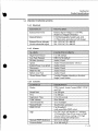
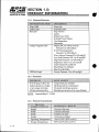

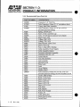


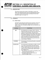


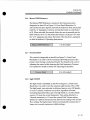


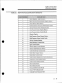
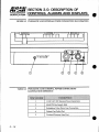


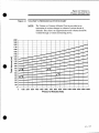

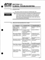
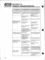
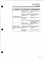


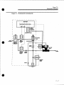


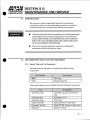


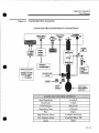
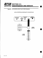


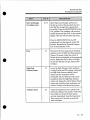
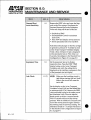

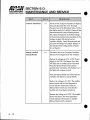
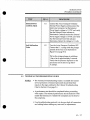
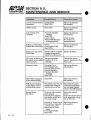
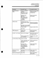

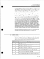
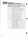
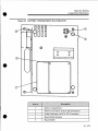

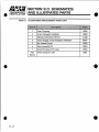
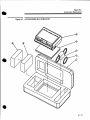
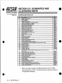
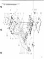


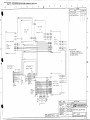

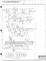


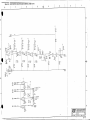

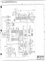

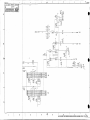


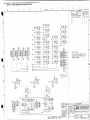

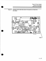

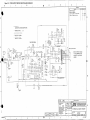


![ENIS System User Manual title]](http://vs1.manualzilla.com/store/data/006883773_1-92ab4b3e10fe186fd4b9ceaf8660b898-150x150.png)