1
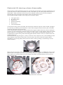
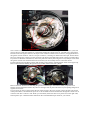
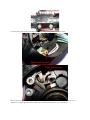
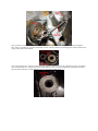
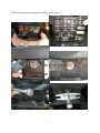
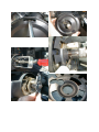
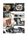
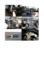
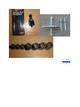
Steering column documentations
Illustrated tilt steering column disassembly
Oliver Scholz
Steering column disassembly pictorial
Jazzman
Repairing GM Tilt steering wheel columns
Curt Martin
Illustrated tilt steering column disassembly
The tilt steering column disassembly seems to be one of the last great mysteries of our time. Nobody likes to do
it, but when you do it’s really not all that bad. At least it seems that way to me. Most people don't know how to
disassemble it, and the description in the Factory Service Manual is sketchy at best. So I have decided to
document the process of tearing into the column, when it was time for me to do so.
This procedure should be useful if you're trying to do one of these repairs:
•
•
•
•
•
•
Turn signal switch
Key buzzer switch
Ignition lock
Ignition lock housing
Wiper switch
Loose tilt mechanism
I tried to take as many pictures as possible, but I still may have missed a step here or there. If I did, I apologize,
but I still hope you find the pictures informative. Some of the writing has become a bit fuzzy due to the JPEG
compression, but GIF’s were just too large.
Some of the things described here can be done without removing the column from the car, however the deeper
you have to go, the easier things get with the column out of the car. Plus, it's really simple to remove the column
and put it back in. It's so much easier to do everything on a desk instead of crammed under the dash! So, I'd
recommend removing the steering wheel and locking plate while the column is in the car, and then remove the
column from the car.
Start off by disconnecting the negative (-) battery connection. This is important, since you'll be fiddling around
with the ignition switch, and you don't want to cause any shorts. Next remove the centre cap/horn button
(depending on your steering wheel). Remove the horn switch contact by pushing it in and turning it 1/4 turn
counter clockwise.
Remove the clip (if present), centre nut (22mm), and pull off the steering wheel. You will need a steering wheel
puller for this. You can get it e.g. at Sears or just about any automotive supplier. Do not attempt to remove the
wheel without this tool! Some wheels are loose enough on the shaft to be pulled manually, but don't use any
brute force approach!
Next remove the plastic lock plate cover by unlocking the tabs with a screwdriver.
Once that's out of the way, you should use a lock plate compressor to push and hold down the lock plate. This
allows you to slide the c-clip retainer onto the tool and release the spring pressure (you can see this in the
pictures). Remove the lock plate and cancelling cam. Be careful not to lose the spring located in the cancelling
cam tower! Remove the Hazard warning switch with a Philips screwdriver. The switch consists of two parts, plus
a spring and a screw. Don't lose them either.
Remove the lock plate spring from the shaft. Next remove the three screws from the turn signal switch. You
must move the turn signal switch in each direction to gain access to all screws. Now remove the Philips screw
from the turn signal lever. Pull the turn signal stalk from the column with the wiper in the off position.
This is where I took the column out of the car. Remove the 11mm bolt attaching the column to the U-joint, and
remove the two 15mm nuts and the two 15mm bolts holding the column in the car. Carefully lower the column.
Disconnect the turn signal connector, the wiper switch connector and the cruise connector, if equipped. Remove
the ignition switch connector. This is a two-part connector; consisting of a black and a white part, both of which
have two locking tabs, so don't force the connectors off. Remove the high beam switch connector (locking tabs!).
If you have an automatic transmission, remove the park lock cable by removing the two tiny Philips screws from
the ignition switch. The column should now be free and you can carefully remove it from the vehicle.
Put the ignition lock in the RUN position and carefully remove the key warning buzzer switch with a paper clip.
Remove the TX20 bolt holding the ignition lock cylinder. Remove the lock cylinder.
Remove the three TX30 screws attaching the ignition lock housing to the column. When you pull the lock
housing off, the high beam actuator may fall out. Getting it back in place can be fun if you're putting things back
together. So beware!
If you're going to remove/replace either the turn signal switch or the wiper switch, remove the four bolts shown
in the picture below, and the harness protector. You can fiddle connector and harness through the column even if
it doesn't seem like it will fit. It will. When you reassemble, these bolts have to be put back in in the right order,
and torqued to spec. Check the Helms manual for the recommended torque values for your vehicle.
To remove the wiper switch, push the pivot pin out of the housing, and remove the switch.
Remove the sector and spring by punching the shaft that goes to the lock cylinder through the sector with a
screwdriver. The spring is held with a small bolt. Put the bolt back in place so you don't lose it.
Next you have to remove the tilt mechanism spring retainer. This is the silver cap with the small rectangular
hole. Insert a screwdriver, push down and make 1/4 turn counter clockwise to disengage the retainer. Remove the
spring and retainer and set aside.
Next is the trickiest part: removal of the pivot pins. GM has a special tool for this (J21854-01), but you probably
don't. Neither did I. So I screwed in a screw and pulled on it with vice grips, wiggling back and forth. Worked
great. But be careful not to break off the screw, or you'll have to drill it out.
Now the hard part is over. Pull on the tilt lever and put the column up as far as you can, then turn it right. You
want to remove this part (see picture). This one actuates the rod that goes to the actual ignition switch.
Just pull the upper part of the tilt housing off. By now you will see a few balls falling from the column. These are
part of the lower bearing; don't lose any one of them!
Now you can see the objects of our desire: the four infamous Torx head bolts. Tighten them well, and a drop of
thread locker may be a good idea. I didn't have a proper size Torx socket, so I used a 6mm Hex socket instead.
Worked great.
Reassembly is basically the reverse of the above. When reassembling, use a torque wrench to torque everything
back to specs. You don't want the column to come apart when you're going 65 mph in heavy traffic! About the
only tricky part when putting the column back together is the high beam switch actuator. Make sure the actuator
is engaging the switch, and hold the column upright. The grease will "stick" the plastic part to the lower column
shroud. Install the lock housing from above, and try to keep the plastic part in place. The picture shows what it
should look like if you did it right. Install the turn signal stalk now to check if the high beam actuator works.
Grease is also a great helper to keep the balls inside a ball bearing, just a hint.
If you have any comments or suggestions (or additions), please feel free to contact me! Oh, and whatever you
do, you do it at your own risk. If you find these pictures helpful, great, but if you break something or I made a
wrong somewhere, don't blame me for anything, just let me know and I'll correct it.
Oliver Scholz
http://www.fieros.de/en/main.html
Steering column disassembly pictorial
Jazzman
www.fiero.com
Repairing GM Tilt steering wheel columns
Description: This procedure covers correcting a "loose" steering wheel. Loose means that the entire upper
portion of the tilt column can be moved from side to side, while the column itself is still firmly bolted to the
chassis and dash. Four bolts in the column that have worked loose due to vibration cause this motion. The four
bolts are about 2 inches in length, but only engage the threads on the lower 1/8th inch, and in this case, no
thread-locking compound was used to secure the bolts.
While I removed the steering column to correct this problem, it can be performed on the car.
Special Tools Needed:
Steering Wheel Puller - (Available from most auto parts stores)
Steering Lock Plate Removing Tool - (Also available from most parts stores)
T-20 and T-30 Torx Bits
Pivot Pin Puller - (More on this later)
Procedure:
1) Disconnect the Battery
2) Use a Screwdriver and remove the Horn Button
3) Remove the Horn Switch (spring loaded plunger, give it a 1/4 turn)
4) Remove the Clip from the end of the steering shaft.
5) Remove the Steering Nut (22mm) from the end of the shaft.
6) Install the Steering wheel puller and remove the wheel. DO NOT attempt to pry, hammer, or pull the
wheel off without this tool. If you can't find a puller, you can fabricate one from steel barstock and three bolts.
7) With the wheel removed, pry off the plastic trim covering the lock plate. There are four tabs, insert a flat
screwdriver into the tab and pry them out.
8) Install the Lock Plate remover. There is no substitute for this. It threads over the steering shaft, pushes the
lock plate in, and allows the retainer (a c-clip) to be removed.
9) Remove the Lock Plate, spring, bearing cup, and spacer from the steering shaft. This will expose the turn
signal switches.
10) Remove the three Phillips head screws retaining the Turn Signal Switch. You must actuate the switch in each
direction to expose the screws. Then remove the Phillips head screw that attaches to turn signal lever to the
switch. Also remove the Emergency Flasher switch from the outside of the column (single Phillips screw in the
center of the knob.)
11) Disconnect the wiring on the steering column, under the dash, to allow enough slack to pull the turn signal
switch away from the housing.
12) Remove the Turn Signal Lever (just pull it straight out.) If equipped with cruise control, just leave the lever
hanging on the single wire.
13) Remove the Key lock Buzzer switch (look for the two long contacts). A paper clip slid down the right side of
the switch will release it so it can be slid straight out.
14) Remove the Ignition Lock retaining pin (T-20 Torx) and slide the ignition switch lock out of the steering
column.
15) Remove the three T-30 Torx screws that hold the upper housing trim in place. Remove the housing trim and
let it hang from the turn signal wiring.
16) Use the Tilt Wheel lever and move the column to it's uppermost position. Then use a padded pair of pliers to
unscrew the lever. This will allow the removal of the housing, Headlight Hi/Low beam linkage, and Steel rod.
17) Before removing the pivot pins, you need to remove the tilt-wheel spring. The spring is held in place by a
sheet metal cap with a square hole in it. Insert a large screwdriver into the square hole, push the cap in, and give
it a 1/4 turn. That will release the cap and allow removal of the spring.
18) Remove the tilt wheel pivot pins (one on each side.) There is a GM tool for doing this. I used a 4mm0.8mm pitch screw and a slide hammer to pull the pins out. This will allow the casting that makes up the front of
the steering column to be removed. The casting must be pulled to the right to release the ignition switch linkage
on the left side of the column.
Note - this linkage is a pair of soft metal castings that allow the ignition switch on the bottom of the column to be
operated by the key lock on the top of the column. If you ever wondered why a car thief would break the plastic
housing on the bottom of the column, this is it. With the lower shroud broken out, this linkage is exposed. It can
be operated with a flat screwdriver.
19) You can now access the 4 bolts in the lower casting that are causing the problem. The bolts have reversetorx heads, but a 1/4" 12pt. socket can be used to tighten the bolts. I applied red Locktite to the last 5 threads on
each bolt and tightened them to 18ft/lbs. The bolts can also be drilled and safety wired in pairs.
Reverse the steps to reassemble the column. The pivot pins can be inserted using a hammer and punch. I
applied Locktite to all of the screws, as the column was re-assembled.
Curt Martin
Ormond Beach, Florida,
[email protected]
http://spacecoastfieros.com/tech/stecol.htm