1
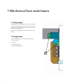
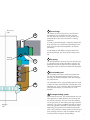
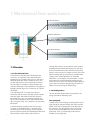
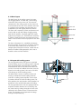
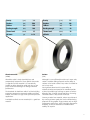
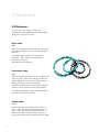
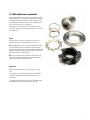
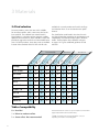
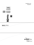
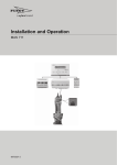
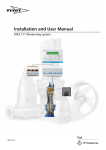
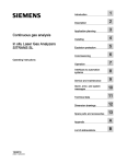
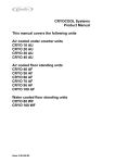
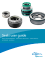
Seals user guide Service and maintenance · Mechanical seals basics · Characteristics Accessories · Materials Seals user guide 1.Basics Page 1.1The principle 1.2Components 1.3Function 1.4Other shaft seals . . . . . . . . . . . . . . . . . . . . . . . . . . . . . . . . . . . . . . . . . . . . . . . . . . . . . . . . . . . . . . . . . . . . . . . . . . . . . . . . . . . . . . . . . . . . . . . . . . . . . . . . . . . . . . . . . . . . . . . . . . . . . . . . . . . . . . . . . . 4 4 6 8 2.Flygt sealing system 2.1General 2.2 Seal types 2.3The plug-in seal 2.4Active sealing 9 14 16 17 . . . . . . . . . . . . . . . . . . . . . . . . . . . . . . . . . . . . . . . . . . . . . . . . . . . . . . . . . . . . . . . . . . . . . . . . . . . . . . . . . . . . . . . . . . . . . . . . . . . . . . . . . . . . . . . . . . . . . . . . . . . . . . . . . . . . . . . . . . 3.Materials 3.1 Face materials 3.2Elastomers 3.3Miscellaneous materials 3.4 Seal selection . . . . . . . . . . . . . . . . . . . . . . . . . . . . . . . . . . . . . . . . . . . . . . . . . . . . . . . . . . . . . . . . . . . . . . . . . . . . . . . . . . . . . . . . . . . . . . . . . . . . . . . . . . . . . . . . 19 22 23 24 4. Service and maintenance 4.1Service 4.2Troubleshooting 4.3Mounting seals 4.4Buffer fluids . . . . . . . . . . . . . . . . . . . . . . . . . . . . . . . . . . . . . . . . . . . . . . . . . . . . . . . . . . . . . . . . . . . . . . . . . . . . . . . . . . . . . . . . . . . . . . . . . . . . . . . . . . . . . . . . . . . . . . . . . . . . . . . . . . . . 25 26 32 39 5. Accessories 5.1 Seal flushing 5.2Leakage sensors . . . . . . . . . . . . . . . . . . . . . . . . . . . . . . . . . . . . . . . . . . . . . . . . . . . . . . . . . . . . 40 41 3 1 Mechanical face seals basics 1.1 The principle The principle of the mechanical face seal is quite simple: Two flat, ring‑shaped surfaces, one stationary and one rotating, are pressed together to create as narrow a gap as possible between them. The smaller the gap between the two surfaces, the less leakage. 1.2 Components The main components of a mechanical face seal are: • Two seal rings • A spring • Two secondary seals • A torque locking system 3 4 Drive unit side 1 The seal rings 4 The flatness of the seal ring faces is crucial for the performance of a mechanical seal. The seal will not seal unless the seal faces are flat, smooth and perpendicular to the shaft, and remain so during operation. A sturdy, symmetrical design is needed to achieve this. If the seal faces are not flat and perpendicular to the shaft, then the seal will leak regardless of all other parameters. A well-designed seal fulfills its primary function of preventing leakage, but also provides a long service life. Sealing interface 1 2 2 The spring The spring loads the seal faces to ensure that they are in constant contact. During operation, however, the dominant force pressing the seal faces together and closing the seal is the pressure exerted from the liquid. 3 The secondary seal The secondary seals form a stationary seal between the seal rings and the retaining structure. They are necessary to eliminate leak paths other than through the seal interface. 4 The secondary seal for a spring-loaded seal face needs to allow for some shaft deflection, misalignment, heat expansion, etc. Since it must be able to accommodate small axial movements, it is referred to as “semidynamic”. 4 The torque locking system Impeller side In mechanical face seals, the friction between the seal faces generates a torque between the seal rings and the retaining structure. This can cause the stationary seal ring to rotate, or the rotating seal ring to become stationary. This can be a problem especially at startup after a long period at standstill. To prevent this from happening, Flygt seals have mechanical torque locks such as pins and slots to firmly anchor the seal rings to their retaining structures. Only the smallest seals rely on friction from O-rings for torque locking. 5 1 Mechanical face seals basics Full film lubrication Mixed film lubrication Boundary lubrication 1.3 Function 1.3.1 The lubrication film The thickness of the lubrication film between the seal faces is an important factor determining the performance of a mechanical face seal. A seal with a thick lubrication film suffers virtually no wear, since the film takes up most of the load from the closing force and there is virtually no contact between the seal faces themselves. This would mean a long life, but leakage would be high. This is referred to as ”full film lubrication.” If the lubrication film is too thin, the seal faces themselves take up most of the load in direct contact with each other and without much help from the lubrication film. In this case, leakage would be very low, but the expected life of the seal would be short due to excessive wear. This is referred to as ”boundary lubrication.” 6 A well-functioning mechanical face seal has what is known as ”mixed lubrication.” This means that the closing force from the spring and the hydraulic pressure is borne by both the hydrodynamic lubrication film and direct contact between the seal faces. Perfectly flat seal faces are not able to create a proper hydrodynamic lubrication film between the seal faces, but the inevitable microscopic deviations from perfect flatness of the seal faces is enough to create such a film. With increasing load on the seal faces, the lubrication changes from “mixed lubrication” to “boundary lubrication.” At some point, the load reaches a critical point where the increased material contact pressure causes the seal to seize. This critical load point depends on the seal face material, the balancing ratio and the ability of the seal’s design to dissipate heat. 1.3.2 Loading factors The face load is determined by two parameters: the spring load and the balancing ratio. The spring load To keep the seal from leaking, the spring load must be high enough to overcome the dynamic forces and the friction force of the semi-dynamic secondary seals. At the same time, the spring load must not be so high that it causes unacceptable levels of wear and heat generation. There is, consequently, little room for variation in the spring load. Unbalanced Ah Balanced Ah A Ah 1 A Ah A Ah 1 A Face load A Ah 1 A Face load Face load Load limit Spring load Duty limit Pump pressure The balancing ratio Therefore, the balancing ratio is the main factor determining a seal’s pressure limit. This ratio is the ratio between the outside area “Ah” of the seal ring on which the pressure of the external liquid is exerted, and the area of the actual seal face, “A.” In Figure 1.2, it can be seen how the duty limit increases with decreasing balancing ratio. This ratio is determined by the design of the seal. 1.3.3 Leakage In a mechanical face seal, there is always a minute transportation of liquid across the faces. This liquid is necessary for the lubrication, so it is not the goal to completely prevent the liquid from entering between the seal faces. Instead, the goal is to keep this liquid leakage at a low and acceptable level. The most important criteria for achieving the necessary low leakage is flat seal faces. Regardless of all other design parameters, if the seal faces are not flat, excess leakage is inevitable. In order to achieve the required flatness, the seal faces must be machined to very narrow tolerances and designed to maintain their flatness under mechanical and thermal load during operation. Pump pressure Pump pressure fig 1.2 Provided that this fundamental condition is met, very low leak rates can be achieved. Fig 1.3 shows a graph for the maximum expected leakage for Flygt seals. It is not possible to give a definite value for seal leakage as it varies between individuals and is strongly dependent on the operating conditions. Most seals will have a leakage well below the value indicated in the graph, while some will reach, or even exceed the leakage limit if conditions are poor. Operating conditions that have a strong influence on leakage are vibration, cavitations and the properties of the sealed media. fig 1.3 7 1 Mechanical face seals basics 1.4 Other shaft seals Soft packings (Gland seals) Common in dry-installed pumps. The main advantages are simplicity, sturdiness and low cost. In submersible pumps however, they are not suitable, as the leakage rate is too high and frequent adjustments are needed. Also, the presence of abrasives causes extensive shaft wear and short life. Lip seals Sometimes referred to as an oil seal as sealing oil is its primary area of application. Lip seals are simple, inexpensive and compact. However, other characteristics, such as low pressure capability and sensitivity to particle contamination of the liquid, make lip seals unsuitable for use as an outer seal in submersibles. In Flygt products from Xylem, lip seals are therefore only used to seal oil, such as in gear boxes in mixers. Fig. 1.6 Pressure and sliding speed limits for different types of shaft seals. fig 1.6 8 2 Flygt sealing system 2.1 General The reliability of a submersible product will never be better than the reliability of its sealing system. Unlike dry-installed equipment, any fluid leaking through the seals will accumulate in the pump or mixer and cannot be drained during operation. To achieve long service intervals and high reliability, exceptional demands are made on the sealing system for submersibles. To ensure that the seals will meet these requirements, Xylem has chosen to design and manufacture its own Flygt seals. As these seals are designed solely for use in submersibles, there is no need for compromise, and seals can be fully optimized for this single purpose. Apart from low leakage rates, the seals are designed to accommodate short shaft overhang. Torque locks and drivers are independent of the shaft rotation and pump pressure acts as a closing force on the seal. Another characteristic of the Flygt seals is that they are versatile. The ultimate goal is that one and the same seal should be able to cope with all applications. Therefore, the outer seal always has hard faces and rubber parts that tolerate high temperatures, even if the pump is used for pumping plain drinking water. With just one standard seal, compatible with most pump or mixer media, the choice of seal is simple. Furthermore, having the seal design and manufacturing in‑house ensures that customers get rapid and accurate responses to any questions or application problems that might arise. The fact that we are the world’s largest producer of submersible pumps and mixers also makes us a major manufacturer of mechanical face seals. Hundreds of thousands seals are produced annually, which provides a more than adequate foundation for continuous research and development. 9 2 Flygt sealing system Inspection chamber Any inner seal leakage is collected in the inspection chamber, a compartment separated from the rest of the drive unit. Plug-In seal Two mechanical face seals in one easy-to-handle unit. Leakage sensor Float leakage sensor FLS10 detects possible inner seal leakage and generates an alarm before the leak reaches a harmful level. Buffer fluid The buffer fluid lubricates and cools the seals. In pumps with an internal cooling system, it also doubles as the coolant for the drive unit. Spin-out™ Spiral groove seal cavity that directs abrasive particles away from the seal faces and out from the seal cavity. 10 2.1.1 Basic layout The basic layout of the sealing system is the same for all Flygt products: an outer seal, a seal housing with buffer fluid, and an inner seal. The two main components in the sealing system are the outer and inner mechanical face seals. These should not be seen as a primary and a secondary seal, but rather two independent seals with slightly different functions. The outer seal is exposed to a harsh environment and must be able to cope with fibrous clogging matter, hard abrasive particles, chemically aggressive media, high pressure, impacts, etc. Therefore outer seals have in general a sturdy design that can withstand a lot of abuse. Hard seal faces are the only option for the outer seal. Inner seal Buffer fluid Outer seal Impeller The inner seal operates in a controlled environment that is less taxing. Since there are no abrasive particles in the buffer fluid, carbon faces can be used as a cheaper option instead of hard faces. Carbon has the benefit of excellent sliding properties, but is not as durable as other seal face materials. 2.1.2 Layout with cooling system The new-generation drive units feature an optional internal cooling system. The cooling system is isolated from the pump media and powered by a propeller located between the inner and the outer seal in the seal unit. Even with this additional function, the basic layout for the sealing system is the same as for drive units without an internal cooling system. The buffer fluid is used as a coolant, and the seal housing is extended to include cooling channels. Seals with a cooling system propeller are also used in products without an internal cooling system. For these products, the only function of the propeller is to provide the inner seal with lubrication and cooling. The new-generation drive units are equipped with an inspection chamber between the seal housing and the stator housing. Leakage through the inner seal is collected in this chamber where it cannot harm the motor. The chamber can be inspected for leakage through an inspection plug. 11 2 Flygt sealing system 2.1.3 Conventional seal cavity Wear in the seal cavity is a common problem in applications with abrasive particles. Even a small concentration of particles can cause severe wear during continuous operation, damaging the seal cavity as well as the seal. The wear is caused by particles becoming trapped in the inner part of the seal cavity, locked in position by the interaction between the boundary current and centrifugal force. The flow of a thin layer of the media close to a surface is affected by that surface. • Rotating surfaces drive a boundary current radially outwards. Wear in traditional seal cavity • Non-rotating surfaces drive the boundary current radially inwards. Particles are centrifuged radially outwards into the inward going boundary current that transports them to the inner part of the seal cavity. The outgoing current along the shaft will not transport the particles all the way out, since they again will be centrifuged radially outwards into the inwards going boundary current. The particles become trapped in the inner part of the seal cavity, causing wear on the seal cavity walls and the seal faces. 2.1.4 Spin-out seal cavity The particles traveling inwards are caught by the spiral grooves. Centrifugal force locks the particles into the grooves, and the general rotation of the liquid in the seal cavity transports them along the spiral path outwards toward the impeller. Spin-out is effective for abrasive particles from 0.05 mm and larger. Since erosive wear on exposed surfaces is caused by particles in this size range, the wear is not just reduced, but virtually eliminated. Wear on seal faces is caused by smaller particles that are not effectively eliminated by the Spin-out feature. Hence, wear here is not eliminated but it is drastically reduced. 12 Particles expelled by Spin-out seal cavity 2.1.5 Positive closing force In Flygt products from Xylem, the seals are designed in such a way that the pump and submergence pressure act as a closing force over the seal faces and not as an opening force. A positive closing force is fundamental to the seal’s ability to handle high pressures. If the force were to be negative, the seal would open like a relief valve at a certain pressure and lose all its sealing effect. In practice, the use of seals with positive closing force means that Flygt products can be subjected to greater submergence depths and be connected in series without the risk of sudden seal failures. 2.1.6 Short shaft Unlike standard seals, the Flygt seals do not have to fit into narrow seal cavities originally intended for gland seals. Being free from this limitation, Flygt seal designs can utilize radial space for their components. This means that seal rings, springs and O‑rings can be adequately dimensioned and seals can be made short. A short seal means that the drive shaft can be made short. A short shaft is a particular advantage when radial loads are present, as in pump volutes. Impeller deflections and bearing loads are minimized, enhancing performance and lengthening the life of the product. 2.1.7 Mechanical torque locks The Flygt seals do not depend on rubber friction for the transmission of torque between the shaft and seal ring. Instead there is always a mechanical device that ensures positive drive. This is somewhat more costly but far more reliable. Because the Flygt static rubber seals do not need to serve as torque locks, they do not need to be clamped tightly. This facilitates both assembly and dismantling. 2.1.8 The seal housing The fluid in the compartment between the seals has three main functions: lubrication, cooling and emulsification of leakage. The lubrication and cooling functions are fairly self evident. Without these, the seal faces would rapidly overheat and seize up. The buffer is also there to dilute and suspend liquids and particles that may leak through the seal. These contaminants might otherwise form deposits which could block or damage the seal. The air volume acts as a pressure buffer to reduce the pressure difference resulting from heat expansion and leakage. 13 2 Flygt sealing system 2.2 Seal types Type B B, as in Bellow seal, referring to the bellow‑like secondary seal between the shaft and the rotating seal ring. The bellow seal is a reliable and sturdy construction that has served well in Flygt B‑pumps for many years. The single coil spring along with the bellow‑shaped secondary seal greatly reduces the risk of hampered spring motion and since there is always metal‑to‑metal contact with the oil housing, good heat dissipation is well provided for. Type G G, as in Grip lock, referring to the shaft lock system. The seal can be mounted on an ungrooved shaft but does not rely on rubber friction for the torque transmission. Its open spring housing design makes it resistant to clogging, and the rubber protected torque drivers make it suitable in abrasive media. The seal is developed to be a sturdy general purpose shaft seal, suitable for all normal Flygt applications. This latest addition to the Flygt seal family replaces older seals in the shaft interval 20 – 35 mm. Type I I, as in Internal spring seal, referring to the protected position of the spring between the shaft and seal rings. This design concept first appeared in the 2201 but has gained popularity also in C‑pumps because of its high resistance to clogging. Type B Type G Type I Type M M, as in Multi‑spring seal, is found in larger pumps and turbines and also as the inner seal in medium‑sized products. For large shaft diameters, the multi‑spring configuration is a very effective design giving short, uncomplicated seals that rarely cause any problems. 14 Type M Type O O, as in Open coil spring seal, is used in smaller B‑pumps. This is a straightforward and durable design that can withstand a lot of abuse. The single coil spring, the flexible mounted O‑ring and well- dimensioned seal rings assure long life in all common applications. Type P P, as in Plug-in seal, has a number of features that make it easier to handle than conventional single seals. The seal comprises an inner and outer seal in one unit that is simply “plugged in” to the product without any special tools being required. The seal is designed for wear and clog resistance, and is suitable for all applications and the toughest media. The plug-in seal is standard in all new products. Type S S, as in Sleeve seal, referring to the sleeve shape of this stationary seal ring. The sleeve seal is a wellproven design that is used in mixers and medium‑sized C‑pumps. Since the spring is placed in the oil housing and the exterior is flushed, the sleeve seal has excellent resistance to clogging and wear. Type O Type P Type S There is also an inverted form of this seal, where the rotating ring is sleeve‑shaped, which is used in 2151 and 2084. Type T T, as in Tube seal, referring to the tube‑like rotating seal ring. Features such as solid seal rings, flushed exterior, a protected spring and metal‑to‑metal contact with the oil housing give outstanding durability even in the harshest environments. Type T 15 2 Flygt sealing system 2.3 The plug-in seal Inner seal Impeller Springs Outer seal Shaft protection sleeve The plug-in seal is a unit incorporating an inner and an outer seal in one easy-to-handle unit. Just like conventional single seals, the inner and the outer seals work independently of each other and form a true double seal system. One obvious benefit of the plugin seal is the simplicity of handling one unit rather than several seal rings and other seal components. But perhaps more importantly, the seal faces are in contact with each other at all times right from the production line, allowing no contamination of the seal faces during service. The plug-in seal is designed to be a universal seal for all Flygt products from Xylem, and to be able to cope with all types of pump media. It is clog-resistant, wearresistant and has excellent cooling capabilities for both the inner and outer seals. The plug-in seal is the only seal available for all new product designs from the 4600 mixer series onwards. 16 The plug-in series of seals ranges, in 6 sizes, from 20 to 80 mm shaft diameter. The outer seal ring pair is available in WCCR and SiC, the inner pair in WCCR, and in WCCR/ceramic for the smaller sizes. The seal unit has an integrated powerful cooling pump for products with internal cooling systems. Plug-in seal units cannot be taken apart and reassembled again. 2 Flygt sealing system 2.4 Active sealing Conventional seals Even the very best of mechanical face seals have a wide spread in performance between different individuals. The majority of the seals have minute leakage barely noticeable over a longer period of time, while others may have leakage that could cause premature failure to the product. The expected worst case scenario for the seal performance is often what sets the recommended service interval. Increased seal performance is a direct increase in product reliability. Stator housing Active sealing Active seals eliminate the spread in performance by completely eliminating the leakage for all seals. The seals actively pump fluid continuously from the low pressure side to the high pressure side, effectively directing the leakage away from the stator housing. Pump media The seal faces are modified to act not just as a conventional barrier against leakage as in conventional face seals, but also to act as a micro pump when needed. Any leakage that slips through the conventional barrier will immediately be pumped back to the high pressure side of the seal by pressure generating grooves. The active seal can only be used in the inner position between the buffer fluid compartment and the drive unit. If used as outer seal, the buffer fluid would be pumped out into the pump media. The grooves Any liquid on the inner diameter of the seal will be transported along the spiral grooves to the outer part of the seal face by the relative motion between the stationary and rotating seal face. The pressure in the fluid increases along the groove by the viscous sheer and will cause liquid to bleed back to the high pressure side of the seal, effectively blocking leakage from the buffer fluid compartment to the stator housing. Inner seal. Buffer fluid Outer seal. Active sealing applied in a Plug-In seal. Any buffer fluid that may leak into the stator housing is immediately pumped back to the buffer fluid chamber. Pressure distribution in grooved seal face. 17 18 3 Materials 3.1 Face materials The choice of material is vitally important to seal performance. A basic rule for high wear resistance is that the material must be harder than the particles present in the pumped medium. Therefore, high hardness is necessary for an outer seal face material, but not sufficient. A good face material must also exhibit good sliding properties, high stiffness, high thermal conductivity and low thermal expansion. On top of this, it must also be chemically compatible with the medium. Only cemented carbide, silicon carbide and aluminium oxide meet the requirements for use in outer seals in Flygt products. • High hardness • High stiffness • Good sliding properties • High thermal conducting • Low thermal expansion 19 3 Materials Density Hardness Stiffness Bending strength Thermal cond. pH-limits [g/cm3]14 [HV3]1300 [GPa]600 [MPa]2600 [W/mK]100 [pH]3–14 [g/cm3]3.1 [HV3]2700 [GPa]420 [MPa]390 [W/mK]100 [pH]0–10 Corrosion resistant cemented carbide (WCCR) Silicon carbide (RSiC) The modern grade of WCCR was developed to combine the outstanding sliding properties of cobaltbound tungsten carbide (WCCo) and the corrosion resistance of the older grade of WCCR. The new WCCR combines the best properties from the older grades of tungsten carbide. The result is a corrosion-resistant material with excellent sliding properties, which allows for high face load and gives good dry-running performance. A great advantage is its high strength, stiffness and toughness which gives the seal rings great shape stability and seal faces that stay flat. Silicon carbide is commercially available in three different grades: sintered, transformed and reactionbonded. Xylem has chosen to use only the reactionbonded grade as its sliding, wear and dimensional stability properties are superior. Good heat conductivity dissipates generated heat away from the seal faces and prevents the lubrication film in the seal interface from evaporating. WCCR is a versatile seal face material that is the best choice in most media, except for strong acids and those media with a high chloride content. 20 Density Hardness Stiffness Bending strength Thermal cond. pH-limits Silicon carbide has several good qualities that make it very suitable for seal faces. High heat conductivity and a self‑lubricating ability give a high surface load capability. As it is the hardest face material of all, its resistance to abrasive wear is excellent. In addition, silicon carbide has good resistance to acidic and chloride liquids. On the other hand, it can have low mechanical strength and poor resistance to alkaline liquids. Mainly because of its brittleness and sliding properties that are not quite as good, silicon carbide is still the second choice behind cemented carbide in Flygt products and is primarily used when the corrosive properties of the liquid demand it. Density Hardness Stiffness Bending strength Thermal cond. pH-limits [g/cm3]3.8 [HV3]1500 [GPa]360 [MPa]300 [W/mK]25 [pH]0–14 Density Hardness Stiffness Bending strength Thermal cond. pH-limits [g/cm3]2.5 [HV3]100 [GPa]20 [MPa]80 [W/mK]20 [pH]– Aluminum oxide (Al203) Carbon (CSb) Aluminium oxide is hard, chemically inert and comparatively inexpensive. These qualities have made it a popular seal face material. It is economically feasible to design aluminium oxide seal rings as one piece, which has advantages for leakage and wear performance. Although it’s not sufficiently hard for use in outer seals, carbon’s excellent sliding properties and its ability to conform to its harder counter face, makes it suitable for use in inner seals. The drawback of aluminium oxide is its inferior sliding properties compared to cemented carbide and silicon carbide. This limits its usage to low speed and pressure applications. Provided these limits are not exceeded, it’s a good face material. One significant draw-back is its poor ability to withstand continuous operation for extended periods of time. Especially large seal rings are prone to surface blistering after a couple of thousand hours of running. Therefore carbon is only used in small seals. Contrary to other face materials, carbon can withstand dry running at lower speeds due to the self-lubricating properties of the graphite. Flygt products only use hightemperature carbon since, apart from high temperature durability, its wear characteristics and dimensional stability are superior. 21 3 Materials 3.2 Elastomers For static seals, two varieties of rubber are predominant: Nitrile (NBR) and fluorocarbon rubber (FPM), often referred to as Viton™. Nitrile rubber (NBR) NBR has very good mechanical properties such as tear resistance and elasticity, and it is not affected by oil and water. The disadvantages of NBR are its temperature limitations (110°C) and its restricted ability to withstand strong acids. NBR is black with no marking. Fluorocarbon rubber (FPM) FPM is usually the standard choice for the rubber parts of the face seals. FPM can be used up to 250°C and will not degrade in most acids and alkalis, with the important exception of very strong alkalis. FPM does not quite match the mechanical properties of NBR: it’s more sensitive to mechanical damage. To facilitate identification, FPM is coloured green but may also be black with a violet dot. Perflour rubber (FFKM) For extremely aggressive media, neither nitrile nor Viton™ may have sufficient chemical resistance. For those media, some seals are available with FKM rubber parts. FKM is a costly material, resistant to most chemicals and with a temperature limit of 240°C. 22 3.3 Miscellaneous materials Other components of the seals, such as springs and retaining devices, are made out of materials suitable for all types of pump or mixer media. Stainless steel and polymeric materials are the most common ones due to their resistance to corrosion. Components not exposed to the media may be of other less corrosion-resistant materials such as bronze and aluminum. Steel The majority of steel parts found in the seals are stainless steel. The two predominant types are: A) AISI 302/304: This is a chromium/nickel alloy that can withstand most of the liquids encountered by Flygt products. The higher carbon content of AISI 302 makes it suitable for springs and circlips, while 304 is preferable for sheet metal parts. B) AISI 329: Apart from chromium and nickel, this alloy also contains molybdenum and can therefore withstand chlorides and acids better. Polymers Only one kind of plastic is used in Flygt face seals: PPS. It has high strength, excellent dimensional stability, high wear properties and excellent resistance to chemicals. Its temperature limit exceeds the one of Nitrile and is comparable to the temperature limit of Viton™. 23 3 Materials 3.4 Seal selection available for a certain product are listed in the Flygt Seal Selection Chart. It can be found on the Xylem intranet. For most products, more than one seal is available for the outer position, and in some cases also for the inner position. The standard face material used in Flygt products is corrosion-resistant tungsten carbide. Optional face materials are often available to cope with particularly aggressive media or to accommodate lower costs. For some products, heavy-duty seals are available instead of the standard version of the seal. All seals The classification code found in the chart for each seal gives information regarding the performance and compatibility of materials and seal types in different media. The description of the different seal types on pages 14-15 gives additional guidance for seal selection. Face materials Elastomers 32 9 31 6/ S C N F S H P PP AI A AI SI 30 2/ SI M FP S AI CS NB b R 3 O 2 iC RS R W CC R 30 4 Miscellaneous Sewage 0 0 0 0 0 0 0 0 0 Fresh water 0 0 0 0 0 0 0 0 0 Sea water 1* 0 0 0 0 0 0 0 0 Abrasive 0 0 1 2 - - - - - pH<3 1 0 0 2 2 0 1 0 0 3<pH<6 0 0 0 2 0 0 0 0 0 6<pH< 10 0 0 0 0 0 0 0 0 0 pH>10 0 2 0 2 0 1 0 0 0 Solvents 0 0 0 0 1 0 0 0 0 Motor oil 0 0 0 0 0 0 0 0 0 Table of compatibility 0 = No effect 1 = Minor to moderate effect 2 = Severe effect. Not recommended! 24 Full information about resistance to specific liquids is found in CREST (Flygt computerized chemical resistant table). * WCCR can be affected in sea water by galvanic corrosion depending on material in surrounding parts. 4 Service and maintenance 4.1 Service Xylem recommends a preventive maintenance program based on Intermediate and Major Services at regular intervals. Inspection and service intervals for the sealing system will differ depending on the product and the conditions of operation. The appropriate intervals are specified in the product’s care and maintenance manual. Products with oil as the buffer fluid When inspecting the oil, it is important to realize that the water content in the oil is not harmful to the seal function at any level. It should only be regarded as an indicator of the leakage rate of the outer seal. The presence of some water in the oil is normal since mechanical face seals, as with all dynamic seals, do not completely eliminate leakage, but rather restrict it to a minute level. If the water content of the oil indicates leakage through the outer seal that exceeds the leakage rate indicated in Fig. 1.3, then the oil should be changed and the outer seal replaced. Water normally separates from oil if left unstirred and the amount can easily be measured. If oil has penetrated the inner seal and leaked into the stator housing at a rate exceeding the one indicated in Fig. 1.3, the leakage should be drained and the inner seal replaced. Products with glycol/water as the buffer fluid The fluid content in the inspection chamber should be checked at intervals according to the service manual. Unless the leakage sensor in the inspection chamber has triggered the alarm during the stipulated service interval, the only action required is to remove the accumulated fluid. If the leakage has triggered the alarm before the end of the service interval, the fluid should be removed and the seal replaced. The level of buffer fluid should be checked. If the level is low, it should be filled up to the level recommended for the product. Never take apart a seal unnecessarily. While running, the seal faces wear into each other, creating matching tracks. Once the seal has been dismantled, these tracks can never be exactly re‑positioned again. Consequently, leakage in a reassembled seal is unavoidable. In practice, this means that a seal that has been in operation for more than a week before being dismantled should be replaced with a new seal. Dry running If the pump has to be test-run dry after servicing, the seals should not, under any circumstances, be allowed to operate without buffer fluid in the seal housing. The heat generated from the seal faces will rapidly destroy the seals without cooling and lubrication from the buffer fluid. With the right amount of fluid in the seal housing, the seals can operate without cooling from the pump media. Seals for shaft diameters greater than 90 mm should be limited to a maximum of 15 minutes of running without external cooling. Leakage The highest expected leakage rate for a seal is indicated in Fig 1.3 on page 7 and can be expressed as 0.05 ml/h for every 25 mm of shaft diameter, i.e., the highest leakage for a 150 mm seal can be said to be 0.3 ml/h. Leakage figures calculated this way should be treated as very approximate. For instance, a higher leakage rate can be expected if the pump is run at a high speed and/or pressure, but the approximations in the table are still helpful in determining if the leakage is reasonable or not. The leakage rate for seals varies between individuals. The average leakage rate for a population of seals are well below the ones indicated in the graph. Troubleshooting on page 24 offers assistance in identifying the cause of a seal malfunction and how to avoid it. High leakage is not necessarily due to the seal itself or anything in its near vicinity. Also, the operating conditions for the whole pump unit must be taken in account. Operational disturbances that have negative impact on seal performance are: • vibrations, • cavitations, • frequent starts and stops, and • other frequent operational transients such as temperature and pressure spikes. These should therefore be kept to a minimum. 25 4 Service and maintenance 4.2 Troubleshooting Leakage is often ascribed to the catch-all cause of a ”bad seal.” A malfunction of a seal can, however, have many very different causes. The leakage might not even originate from the face seal. Inspection screws and static seals are also possible sources of leakage. If the cause is properly identified, the probability of a successful repair is vastly improved. The following is a list of potential seal problems, along with advice on appropriate action. Troubleshooting seal faces Corrosion Is found exclusively on cemented carbide seal faces and can be identified by scratching the surface with a knife or needle. If material comes loose, the seal face is corroded. Action: • Check the ”Seal Selection Chart” and the ”Table of Compatibility” on page 22 for a more corrosion‑ resistant seal face material. Thermo cracks Are caused by thermal overloads resulting from, for example, extensive dry‑running or excessive seal face pressure. Excessively high face loads can, in turn, be caused by a spring that is fully compressed because of incorrect mounting (or mounting dimensions), or a media pressure in excess of the seal’s pressure limit. Action: • Check the mounting of the seal. • Check its operating conditions. • If the faces are made of aluminium oxide, upgrade to cemented carbide or silicon carbide. • Use level switches to eliminate dry‑running. 26 Misalignment Is most often due to an incorrectly positioned seal ring. The picture shows a stationary seal ring that has been either incorrectly mounted or pushed out of position by excessive pressure in the oil housing. Action: • Check the mounting and retaining parts. • Make sure that the shaft runs true (see “Shaft Deviations,” page 29). Pitting or blistering Is encountered on carbon faces and is most likely to occur on pumps that run continuously. Action: • Change to cemented carbide in both seal faces. Slide marks Appear on the backside of the seal ring and indicate that the seal ring has been rotating relative to its retaining structure (when it should have been stationary). Action: • Check mounting and torque locks. 27 4 Service and maintenance Troubleshooting O‑rings Chemical attack Appears in the form of cracks, discoloration or volume increase. A volume increase may manifest itself by extrusion distortions. Action: • Check the media and select compatible material. Irreversible set Failure of the O‑ring to adopt its original shape after being dismantled. This is caused by excessive temperature. Action: • Check for low oil volume if the inner seal is affected. Tearing Usually originates from mounting without grease and/ or sharp edges on the components surrounding the O‑ring. Always use plenty of grease when mounting seals and smooth all surrounding surfaces with an emery cloth before assembly. Action: • Replace O‑rings. • Check for sharp edges in the O-ring chamfer. Mechanical wear Or a “burnt” appearance, is most often caused by incorrect rotation between the seal ring and its retaining structure. Action: • Check mounting and torque locks. 28 Troubleshooting other parts Broken spring Usually the consequence of angular misalignment of the stationary seal ring in relation to the shaft. This forces the spring‑loaded ring to constantly alter its position, which eventually leads to fatigue and rupturing of the spring. Another possible cause is chemical attack. Action: • Check the mounting. • Check the corrosive properties of the media and select appropriate materials. • Check that the shaft runs true according to the “Shaft Deviations,” page 29. Clogging Occurs when the spring loaded face fails to exert pressure against the opposite face because its spring, and/or semi‑dynamic static seal, is clogged by debris. Action: • Change to a more clog‑resistant design. • Consider seal flushing. Jammed spring action Caused by wear between moving and stationary parts in the spring arrangement. It’s particulary important to check for this when replacing seals of Type S design because the spring arrangement is not included in the replacement unit. Action: • Replace or polish worn parts. • Check that the shaft runs true according to “Shaft Deviations,” page 29. 29 4 Service and maintenance Inspection screws Can easily be forgotten as a source of leakage. Action: • Check both the O‑ring and the screw condition. • Replace if necessary. 30 Shaft deviations Are harmful to the seal’s performance and must be kept within narrow limits. Action: • Gauge the shaft and the seal seat in accordance to fig 4.2. Shaft diameter* mm Max deviation mm A B C ≤ 35 0.03 0.1 0.1 45-80 0.05 0.03 0.1 ≥ 90 0.05 0.1 0.1 *At seal position fig 4.2 31 4 Service and maintenance 4.3 Mounting seals Although the seal rings are made from extremely hard materials such as Tungsten carbide or Silicon carbide, the seals should be handled with care. The extreme flatness tolerance of the seal faces allows for no distortion from physical shock or contamination by even the smallest of particles. The gap between the seal faces is on average less than 0.5 micrometers, which means that even small particles from a thumb print could separate the seal faces enough to create leakage. Normally, particles on the seal faces are worn away shortly after startup, but metal particles can cause leakage for a long time before they are worn away. The seals are a pump’s most delicate parts. Extra care and attention while mounting seals will be repaid by greater operational reliability. • Keep seal faces clean • Do not distort the seal rings by using excessive force • Use the recommended service tools • Follow the mounting instructions enclosed with the seal unit • Examine the shaft, O-ring grooves and seal seat for scratches and damage. Note where to apply oil and where to apply grease. Oil, represented by an oil can in the mounting instructions, should, without exception, be applied to the seal faces. The dynamic O-ring should always be lubricated with grease, represented by a grease gun in the mounting instruction. The O-ring for the stationary seal ring should be lubricated with either grease or oil to facilitate mounting. Grease must not be used if the stationary seal ring does not have a mechanical torque lock. 32 Remounting seals A seal that has been in operation cannot be remounted after being removed from the pump. After a period of operation, the seal faces wear microscopic grooves on each other that match exactly. If a seal that has been tight before servicing the pump is remounted after the service, these grooves will not match again exactly and the seal is likely to leak. This applies to all mechanical face seals regardless of design. Mounting, general Preparing the seal seat Clean the seal seat and shaft thoroughly and use emery cloth to smooth the surface if necessary. Lubricate the dynamic O-ring with grease. Apply the grease on the shaft or sleeve seal ring so that the grease is collected by the O-ring when the seal ring is slid into position. Clean the seal faces thoroughly with solvent and dust free paper. Even the smallest particles can cause excessive leakage. Apply a couple of drops of oil on the seal faces before closing the seal. 33 4 Service and maintenance Mounting Griploc seals 1. Wash your hands. Keep everything that might come into contact with the seal clean. Even the smallest particles left on the seal faces could cause a leakage. 2. Clean shaft and seal seat. Check for scratches that may cause O-rings to leak. 3. Lubricate the static O-ring. Oil must be used if the seal ring does not have a mechanical torque lock. Otherwise grease can be used. 4. Push the seal ring into position in its seat. Clean the seal face thoroughly with a solvent if contaminated by fingers or tools. 34 5. Apply a couple drops of oil to the seal face. 6. Clean the shaft with a solvent. Mount the rotating unit on the shaft by pushing it in position with the disposable mounting tool. 7. Keep the seal compressed with the mounting tool while tightening the lock screw, initially only by turning and then adding axial force on the screw driver. If the screw driver is forced axially before the lock spring is gripping the shaft, there is a risk that the seal will be pushed out of correct position. Remove the black plastic mounting tool. Correctly mounted seals should have this distance of 1 mm. ➤ 8. Check that the seal runs true. If not, put the mounting tool back on the seal, untighten the lock screw, push the seal firmly in position with the tool and then retighten the lock screw, taking care not to push the seal out of position with the screw driver. 35 4 Service and maintenance Mounting plug-in seals 1. Wash your hands. Keep everything that might come into contact with the seal clean. Even the smallest particles left on the seal face could cause a leakage. 2. Clean, check for scratches and grease the shaft. 3. Push the seal unit into position by applying force on both the stationary and rotating parts. Make sure the drive geometries of the seal and shaft match. 36 4. Apply the retaining ring by sliding it over the shaft cone until it snaps into its groove. Do not use retaining ring pliers. Give the retaining ring a couple of nudges to help it enter the bottom of the groove to ensure wobble-free operation. 5. Make sure that the O-ring in the seal housing cover is in place (not Mixer 46304670). Lock the seal unit in position by mounting the seal housing cover. 6. Apply some grease inside the rubber cuff to protect the shaft and retaining ring from corrosion and dirt. 37 4 Service and maintenance Check for leakage After mounting a new seal, the seal’s tightness should be checked. Leakage can be detected by applying underpressure in the seal housing and then monitoring any change of pressure over time. For safety reasons, overpressure should never be used for leakage detection since even moderate pressure can cause severe injury in case of structural failure. Vacuum pump Valve Pressure change leakage test A negative differential pressure of about 0.5-0.7 bar (0.5-0.3 bar absolute pressure) is applied in the empty seal housing. After applying the correct pressure, the evacuation line is closed by a valve and the change of pressure is monitored using a pressure gauge. Maximum allowed change of pressure over a certain period of time is calculated as: Example: Pd=0.5 bar ∆P max = 0.017 · Pd · t/V V=5l Where 38 t=60min ∆P max is the maximum allowed pressure change in the test object [bar] Pd is the differential pressure [bar] t is the test time [minutes] V is is the volume of the test object [liter] Max pressure drop ∆P=0.017*0.5*60/5=0.1 bar Total volume in seal housing is aproximately the specified oil volume times 1.2 4.4 Buffer fluids The standard buffer fluid in the seal housing is paraffin oil, however in some products and pumps with an internal cooling system, the oil is replaced with a 30% solution of monopropylene glycol. Both of these buffer fluids are easily obtained, nontoxic and approved for usage in the food industry. Other oils can be used in pumps without internal cooling systems as long as they are compatible with the rubber parts, such as O-rings and lip seals, and the viscosity does not exceed ISO VG 32. Additives in the oil are not needed but are not harmful as long as they also are compatible with all the materials in the sealing system. The amount of buffer fluid should be filled according to specification for each product. A too high buffer fluid level will create an overpressure in the seal housing and possibly harm the seals. If the buffer fluid level is too low, the inner seal may not get sufficient cooling and may fail due to overheating. In some products the air volume in the seal housing is replaced by pieces of pressure equlizing foam. It is of utmost importance that the new foam pieces are put back into the seal housing after service. 39 5 Accessories 5.1 Seal flushing Under severe conditions, seal life can be considerably extended if a system of seal flushing is installed. Seal flushing ensures that a clean medium surrounds the seal and that contaminants are kept away. Furthermo‑ re, the flushing medium reduces temperature, which is beneficial to seal performance. For those reasons, seal flushing is a widespread measure for prolonging the life of pumps used in industrial processes. For mixers, Xylem can supply “ready‑to‑install” kits for either water or air flushing. The air system is used when dilution of the working medium is not permissible. The folder “Control Equipment for Seal Flushing” describes the system in detail. At this point in time, there are no flushing kits for C‑pumps available from the factory. Some important aspects will be given here but it is recommended that you contact the Head Office for specific information. When seal flushing is applied to pumps, it is highly advisable to control the flow with a flow regulator and not a pressure regulator. In seal flushing, the parameter to control is the flow. For mixers, this is achieved with a pressure regulator as the pressure outside the seal chamber, the submergence depth, is constant. In pumps, however, the pressure out‑ side the seal chamber consists of both submergence depth and pump pressure. If a pressure regulator is used, the seal chamber will be over‑pressurized when the pump is shut down and the flow restrictor may be damaged. Air flushing is not applicable to pumps. 40 5.2 Leakage sensors In order to protect the electric motor from leakage‑ related damage, two kinds of leakage sensors are available: the CLS and the FLS. Capacity leakage sensor (CLS) This device is placed in the oil housing and connected to the monitoring relay CAS/MAS. By sensing changes in the oil’s capacitive properties when mixed with water, the CLS triggers an alarm when the water content exceeds 30%. Water mixed into the oil does not hurt the product, but the CLS can be used to evaluate the performance of the outer seal. Float switch leakage sensor (FLS) The FLS is placed in the stator housing or the inspection chamber and senses the accumulated liquid using a float. The FLS is connected to the monitoring relay. A FLS alarm calls for more immediate action than that of the CLS, as the FLS alarm tells that leakage has penetrated into the motor, while the CLS alarm only indicates that this might happen. 41 Notes 42 Notes 43 e 1) The tissue in plants that brings water upward from the roots; 2) a leading global water technology company. We’re 12,000 people unified in a common purpose: creating innovative solutions to meet our world’s water needs. Developing new technologies that will improve the way water is used, conserved, and re-used in the future is central to our work. We move, treat, analyze, and return water to the environment, and we help people use water efficiently, in their homes, buildings, factories and farms. In more than 150 countries, we have strong, long-standing relationships with customers who know us for our powerful combination of leading product brands and applications expertise, backed by a legacy of innovation. For more information on how Xylem can help you, go to www.xyleminc.com Xylem, Inc. 14125 South Bridge Circle Charlotte, NC 28273 Tel 704.409.9700 Fax 704.295.9080 855-XYL-H2O1 (855-995-4261) www.xyleminc.com Flygt is a trademark of Xylem Inc. or one of its subsidiaries. © 2015 Xylem, Inc. JUNE 2015 FB206-892382 • Flygt Seals User Guide • 7/2015 • NACT Xylem |'zīl m|