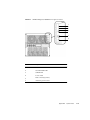
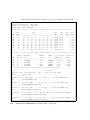
1
SPARC Enterprise M4000/M5000 Servers
Installation Guide
Part No.: E26845-01
Manual Code: C120-E351-08EN
February 2012
Copyright © 2007, 2012, Oracle and/or its affiliates. All rights reserved.
Fujitsu Limited provided technical input and review on portions of this material.
Oracle and/or its affiliates and Fujitsu Limited each own or control intellectual property rights relating to products and technology described in this
document, and such products, technology and this document are protected by copyright laws, patents, and other intellectual property laws and
international treaties.
This document and the product and technology to which it pertains are distributed under licenses restricting their use, copying, distribution, and
decompilation. No part of such product or technology, or of this document, may be reproduced in any form by any means without prior written
authorization of Oracle and/or its affiliates and Fujitsu Limited, and their applicable licensors, if any. The furnishings of this document to you does not
give you any rights or licenses, express or implied, with respect to the product or technology to which it pertains, and this document does not contain or
represent any commitment of any kind on the part of Oracle or Fujitsu Limited, or any affiliate of either of them.
This document and the product and technology described in this document may incorporate third-party intellectual property copyrighted by and/or
licensed from the suppliers to Oracle and/or its affiliates and Fujitsu Limited, including software and font technology.
Per the terms of the GPL or LGPL, a copy of the source code governed by the GPL or LGPL, as applicable, is available upon request by the End User. Please
contact Oracle and/or its affiliates or Fujitsu Limited.
This distribution may include materials developed by third parties.
Parts of the product may be derived from Berkeley BSD systems, licensed from the University of California. UNIX is a registered trademark in the U.S. and
in other countries, exclusively licensed through X/Open Company, Ltd.
Oracle and Java are registered trademarks of Oracle and/or its affiliates. Fujitsu and the Fujitsu logo are registered trademarks of Fujitsu Limited.
All SPARC trademarks are used under license and are registered trademarks of SPARC International, Inc. in the U.S. and other countries. Products bearing
SPARC trademarks are based upon architectures developed by Oracle and/or its affiliates. SPARC64 is a trademark of SPARC International, Inc., used
under license by Fujitsu Microelectronics, Inc. and Fujitsu Limited. Other names may be trademarks of their respective owners.
United States Government Rights - Commercial use. U.S. Government users are subject to the standard government user license agreements of Oracle
and/or its affiliates and Fujitsu Limited and the applicable provisions of the FAR and its supplements.
Disclaimer: The only warranties granted by Oracle and Fujitsu Limited, and/or any affiliate of either of them in connection with this document or any
product or technology described herein are those expressly set forth in the license agreement pursuant to which the product or technology is provided.
EXCEPT AS EXPRESSLY SET FORTH IN SUCH AGREEMENT, ORACLE OR FUJITSU LIMITED, AND/OR THEIR AFFILIATES MAKE NO
REPRESENTATIONS OR WARRANTIES OF ANY KIND (EXPRESS OR IMPLIED) REGARDING SUCH PRODUCT OR TECHNOLOGY OR THIS
DOCUMENT, WHICH ARE ALL PROVIDED AS IS, AND ALL EXPRESS OR IMPLIED CONDITIONS, REPRESENTATIONS AND WARRANTIES,
INCLUDING WITHOUT LIMITATION ANY IMPLIED WARRANTY OF MERCHANTABILITY, FITNESS FOR A PARTICULAR PURPOSE OR NONINFRINGEMENT, ARE DISCLAIMED, EXCEPT TO THE EXTENT THAT SUCH DISCLAIMERS ARE HELD TO BE LEGALLY INVALID. Unless
otherwise expressly set forth in such agreement, to the extent allowed by applicable law, in no event shall Oracle or Fujitsu Limited, and/or any of their
affiliates have any liability to any third party under any legal theory for any loss of revenues or profits, loss of use or data, or business interruptions, or for
any indirect, special, incidental or consequential damages, even if advised of the possibility of such damages.
DOCUMENTATION IS PROVIDED “AS IS” AND ALL EXPRESS OR IMPLIED CONDITIONS, REPRESENTATIONS AND WARRANTIES,
INCLUDING ANY IMPLIED WARRANTY OF MERCHANTABILITY, FITNESS FOR A PARTICULAR PURPOSE OR NON-INFRINGEMENT, ARE
DISCLAIMED, EXCEPT TO THE EXTENT THAT SUCH DISCLAIMERS ARE HELD TO BE LEGALLY INVALID.
Please
Recycle
Copyright © 2007, 2012, Oracle et/ou ses sociétés affiliées. Tous droits réservés.
Fujitsu Limited a fourni et vérifié des données techniques de certaines parties de ce composant.
Oracle et/ou ses sociétés affiliées et Fujitsu Limited détiennent et contrôlent chacune des droits de propriété intellectuelle relatifs aux produits et
technologies décrits dans ce document. De même, ces produits, technologies et ce document sont protégés par des lois sur le copyright, des brevets,
d’autres lois sur la propriété intellectuelle et des traités internationaux.
Ce document, le produit et les technologies afférents sont exclusivement distribués avec des licences qui en restreignent l’utilisation, la copie, la
distribution et la décompilation. Aucune partie de ce produit, de ces technologies ou de ce document ne peut être reproduite sous quelque forme que ce
soit, par quelque moyen que ce soit, sans l’autorisation écrite préalable d’Oracle et/ou ses sociétés affiliées et de Fujitsu Limited, et de leurs éventuels
bailleurs de licence. Ce document, bien qu’il vous ait été fourni, ne vous confère aucun droit et aucune licence, expresses ou tacites, concernant le produit
ou la technologie auxquels il se rapporte. Par ailleurs, il ne contient ni ne représente aucun engagement, de quelque type que ce soit, de la part d’Oracle ou
de Fujitsu Limited, ou des sociétés affiliées de l’une ou l’autre entité.
Ce document, ainsi que les produits et technologies qu’il décrit, peuvent inclure des droits de propriété intellectuelle de parties tierces protégés par
copyright et/ou cédés sous licence par des fournisseurs à Oracle et/ou ses sociétés affiliées et Fujitsu Limited, y compris des logiciels et des technologies
relatives aux polices de caractères.
Conformément aux conditions de la licence GPL ou LGPL, une copie du code source régi par la licence GPL ou LGPL, selon le cas, est disponible sur
demande par l’Utilisateur final. Veuillez contacter Oracle et/ou ses sociétés affiliées ou Fujitsu Limited.
Cette distribution peut comprendre des composants développés par des parties tierces.
Des parties de ce produit peuvent être dérivées des systèmes Berkeley BSD, distribués sous licence par l’Université de Californie. UNIX est une marque
déposée aux États-Unis et dans d’autres pays, distribuée exclusivement sous licence par X/Open Company, Ltd.
Oracle et Java sont des marques déposées d’Oracle Corporation et/ou de ses sociétés affiliées. Fujitsu et le logo Fujitsu sont des marques déposées de
Fujitsu Limited.
Toutes les marques SPARC sont utilisées sous licence et sont des marques déposées de SPARC International, Inc., aux États-Unis et dans d’autres pays. Les
produits portant la marque SPARC reposent sur des architectures développées par Oracle et/ou ses sociétés affiliées. SPARC64 est une marque de SPARC
International, Inc., utilisée sous licence par Fujitsu Microelectronics, Inc. et Fujitsu Limited. Tout autre nom mentionné peut correspondre à des marques
appartenant à d’autres propriétaires.
United States Government Rights - Commercial use. U.S. Government users are subject to the standard government user license agreements of Oracle
and/or its affiliates and Fujitsu Limited and the applicable provisions of the FAR and its supplements.
Avis de non-responsabilité : les seules garanties octroyées par Oracle et Fujitsu Limited et/ou toute société affiliée de l’une ou l’autre entité en rapport
avec ce document ou tout produit ou toute technologie décrits dans les présentes correspondent aux garanties expressément stipulées dans le contrat de
licence régissant le produit ou la technologie fournis. SAUF MENTION CONTRAIRE EXPRESSÉMENT STIPULÉE DANS CE CONTRAT, ORACLE OU
FUJITSU LIMITED ET LES SOCIÉTÉS AFFILIÉES À L’UNE OU L’AUTRE ENTITÉ REJETTENT TOUTE REPRÉSENTATION OU TOUTE GARANTIE,
QUELLE QU’EN SOIT LA NATURE (EXPRESSE OU IMPLICITE) CONCERNANT CE PRODUIT, CETTE TECHNOLOGIE OU CE DOCUMENT,
LESQUELS SONT FOURNIS EN L’ÉTAT. EN OUTRE, TOUTES LES CONDITIONS, REPRÉSENTATIONS ET GARANTIES EXPRESSES OU TACITES, Y
COMPRIS NOTAMMENT TOUTE GARANTIE IMPLICITE RELATIVE À LA QUALITÉ MARCHANDE, À L’APTITUDE À UNE UTILISATION
PARTICULIÈRE OU À L’ABSENCE DE CONTREFAÇON, SONT EXCLUES, DANS LA MESURE AUTORISÉE PAR LA LOI APPLICABLE. Sauf mention
contraire expressément stipulée dans ce contrat, dans la mesure autorisée par la loi applicable, en aucun cas Oracle ou Fujitsu Limited et/ou l’une ou
l’autre de leurs sociétés affiliées ne sauraient être tenues responsables envers une quelconque partie tierce, sous quelque théorie juridique que ce soit, de
tout manque à gagner ou de perte de profit, de problèmes d’utilisation ou de perte de données, ou d’interruptions d’activités, ou de tout dommage
indirect, spécial, secondaire ou consécutif, même si ces entités ont été préalablement informées d’une telle éventualité.
LA DOCUMENTATION EST FOURNIE « EN L’ÉTAT » ET TOUTE AUTRE CONDITION, DÉCLARATION ET GARANTIE, EXPRESSE OU TACITE, EST
FORMELLEMENT EXCLUE, DANS LA MESURE AUTORISÉE PAR LA LOI EN VIGUEUR, Y COMPRIS NOTAMMENT TOUTE GARANTIE
IMPLICITE RELATIVE À LA QUALITÉ MARCHANDE, À L’APTITUDE À UNE UTILISATION PARTICULIÈRE OU À L’ABSENCE DE
CONTREFAÇON.
Contents
Preface
1.
Installation Overview
1.1
2.
ix
Installation Workflow
1–1
Preparing to Install the Server
2–1
2.1
Safety Precautions
2.2
Before Installing the Server
2.2.1
2.3
3.
1–1
2–1
Facility Power
2–2
2–2
2.2.1.1
Facility Power Requirements and Characteristics
2.2.1.2
Grounding
2–7
2.2.2
Cable Connections
2.2.3
Checking the Installation Location
Tools and Equipment
Installing the Server
2–4
2–8
2–8
2–9
3–1
3.1
Checking Components
3–1
3.2
Connecting Input Power Cords
3–2
3.2.1
Connecting a UPS Unit
3–3
3.2.2
Verifying the Power Input Connections Before Applying Power
3–4
v
3.3
3.4
3.5
4.
Connecting the Administration Console
3.3.1
Connecting the Console
3.3.2
Initializing the XSCF Unit
Powering On the Server
3–7
3–9
3–10
3.4.1
Verifying the Configuration
3.4.2
Checking the Dual-Power Feed
3–11
3–15
Connecting Additional Peripheral Devices
Connecting the Domains to the Network
3–15
4–1
4.1
Overview of Network Configuration
4.2
Connecting to the Network
4.3
Verifying the Network Connection
4.4
Verifying Operation by Running Oracle VTS Software
A. System Views
4–1
4–1
4–2
A–1
A.1
SPARC Enterprise M4000 Server Views
A–1
A.2
SPARC Enterprise M5000 Server Views
A–5
A.3
Operator Panel Overview
B. Fault Isolation
A–9
B–1
B.1
Corrective Actions to Common Problems
B.2
Using the Diagnostic Commands
B–1
B–2
B.2.1
Using the showhardconf Command
B.2.2
Using the showlogs Command
B.2.3
Using the showstatus Command
B.2.4
Using the fmdump Command
B.2.5
vi
3–5
B–2
B–5
B–6
B–6
B.2.4.1
fmdump -V Command
B–6
B.2.4.2
fmdump -e Command
B–7
Using the fmadm faulty Command
B–7
B.2.5.1
B–8
fmadm config Command
SPARC Enterprise M4000/M5000 Servers Installation Guide • February 2012
4–2
B.2.6
B.3
Using the fmstat Command
B–8
Traditional Oracle Solaris Diagnostic Commands
B.3.1
Using the iostat Command
B.3.1.1
B.3.2
Options
B–17
B–17
Using the ps Command
B.3.6.1
B.3.7
Options
B–18
B–18
Using the prstat Command
B.3.7.1
Options
B–16
B–16
Using the ping Command
B.3.5.1
B.3.6
Options
B–14
B–14
Using the netstat Command
B.3.4.1
B.3.5
Options
B–11
B–11
Using the prtconf Command
B.3.3.1
B.3.4
Options
B–9
B–9
Using the prtdiag Command
B.3.2.1
B.3.3
Options
B–9
B–19
B–20
Contents
vii
viii
SPARC Enterprise M4000/M5000 Servers Installation Guide • February 2012
Preface
This guide describes how to install and set up the SPARC Enterprise M4000/M5000
servers from Oracle and Fujitsu. This document is intended for authorized service
providers. References herein to the M4000 server or M5000 server are references to
the SPARC Enterprise M4000 or SPARC Enterprise M5000 server.
This preface includes the following sections:
■
“Audience” on page ix
■
“Related Documentation” on page x
■
“Text Conventions” on page xi
■
“Notes on Safety” on page xii
■
“Syntax of the Command-Line Interface (CLI)” on page xii
■
“Documentation Feedback” on page xiii
Audience
This guide is written for experienced system administrators with working
knowledge of computer networks and advanced knowledge of the Oracle Solaris
Operating System (Oracle Solaris OS).
ix
Related Documentation
All documents for your server are available online at the following locations.
Documentation
Link
Sun Oracle software- http://www.oracle.com/documentation
related manuals
(Oracle Solaris OS,
and so on)
Fujitsu documents
http://www.fujitsu.com/sparcenterprise/manual/
Oracle M-series
server documents
http://www.oracle.com/technetwork/documentation/sparcmseries-servers-252709.html
The following table lists titles of related documents.
SPARC Enterprise M4000/M5000 Servers Documents
SPARC Enterprise M4000/M5000 Servers Site Planning Guide
SPARC Enterprise Equipment Rack Mounting Guide
SPARC Enterprise M4000/M5000 Servers Getting Started Guide*
SPARC Enterprise M4000/M5000 Servers Overview Guide
SPARC Enterprise M3000/M4000/M5000/M8000/M9000 Servers Important Legal and Safety Information
SPARC Enterprise M4000/M5000 Servers Safety and Compliance Manual
External I/O Expansion Unit Safety and Compliance Guide
SPARC Enterprise M4000 Server Unpacking Guide
SPARC Enterprise M5000 Server Unpacking Guide
SPARC Enterprise M4000/M5000 Servers Installation Guide
SPARC Enterprise M4000/M5000 Servers Service Manual
External I/O Expansion Unit Installation and Service Manual
SPARC Enterprise M3000/M4000/M5000/M8000/M9000 Servers Administration Guide
SPARC Enterprise M3000/M4000/M5000/M8000/M9000 Servers XSCF User’s Guide
SPARC Enterprise M3000/M4000/M5000/M8000/M9000 Servers XSCF Reference Manual
SPARC Enterprise M4000/M5000/M8000/M9000 Servers Dynamic Reconfiguration (DR) User’s Guide
SPARC Enterprise M4000/M5000/M8000/M9000 Servers Capacity on Demand (COD) User’s Guide
x
SPARC Enterprise M4000/M5000 Servers Installation Guide • February 2012
SPARC Enterprise M4000/M5000 Servers Documents
SPARC Enterprise M3000/M4000/M5000/M8000/M9000 Servers Product Notes†
SPARC Enterprise M4000/M5000 Servers Product Notes
External I/O Expansion Unit Product Notes
SPARC Enterprise M3000/M4000/M5000/M8000/M9000 Servers Glossary
* All getting started guides are printed documents.
† For XCP version 1100 or later
Text Conventions
This manual uses the following fonts and symbols to express specific types of
information.
Fonts/symbols
Meaning
Example
AaBbCc123
What you type, when contrasted
with on-screen computer output.
This font represents the example of
command input in the frame.
XSCF> adduser jsmith
AaBbCc123
The names of commands, files, and
directories; on-screen computer
output.
This font represents the example of
command input in the frame.
XSCF> showuser -P
User Name:
jsmith
Privileges:
useradm
auditadm
Italic
Indicates the name of a reference
manual
See the SPARC Enterprise
M3000/M4000/M5000/M8000/M900
0 Servers XSCF User’s Guide.
""
Indicates names of chapters,
sections, items, buttons, or menus
See Chapter 2, "System Features."
Preface
xi
Notes on Safety
Read the following documents thoroughly before using or handling any SPARC
Enterprise M4000/M5000 server:
■
SPARC Enterprise M3000/M4000/M5000/M8000/M9000 Servers Important Legal and
Safety Information
■
SPARC Enterprise M4000/M5000 Servers Safety and Compliance Guide
Syntax of the Command-Line Interface
(CLI)
The command syntax is as follows:
xii
■
A variable that requires input of a value must be put in Italics.
■
An optional element must be enclosed in [].
■
A group of options for an optional keyword must be enclosed in [] and delimited
by |.
SPARC Enterprise M4000/M5000 Servers Installation Guide • February 2012
Documentation Feedback
If you have any comments or requests regarding this document, go to the following
websites:
■
For Oracle users:
http://www.oracle.com/goto/docfeedback
Include the title and part number of your document with your feedback.
SPARC Enterprise M4000/M5000 Servers Installation Guide, E26845-01
■
For Fujitsu users:
http://www.fujitsu.com/global/contact/computing/sparce_index.html
Preface
xiii
xiv
SPARC Enterprise M4000/M5000 Servers Installation Guide • February 2012
CHAPTER
1
Installation Overview
This chapter provides the process for installing the servers.
1.1
Installation Workflow
Installing a server requires the steps in FIGURE 1-1.
1-1
FIGURE 1-1
Workflow Required for Installation
Preparation
Checking the cables and environmental conditions.
“Before Installing the Server” on page 2-2
Installation and
checking the
power supply
Connecting the power cords
“Connecting Input Power Cords” on page 3-2
Connecting the console
“Connecting the Administration Console” on page 3-5
Powering on the server
“Powering On the Server” on page 3-10
Installing additional peripheral devices
“Connecting Additional Peripheral Devices” on page 3-15
Environmental
Setup
1-2
Setting up the network
“Overview of Network Configuration” on page 4-1
SPARC Enterprise M4000/M5000 Servers Installation Guide • February 2012
CHAPTER
2
Preparing to Install the Server
This chapter describes the items you are required to check, the environmental
requirements for installation, installation areas, and other related matters. It contains
the following sections:
2.1
■
Section 2.1, “Safety Precautions” on page 2-1
■
Section 2.2, “Before Installing the Server” on page 2-2
■
Section 2.3, “Tools and Equipment” on page 2-9
Safety Precautions
To protect both yourself and the equipment, observe the following precautions when
possible:
■
Observe the precautions, warnings, and notes on handling shown on the server.
■
Use an electrostatic discharge (ESD) jack or wrist or foot strap when possible.
■
Do not block any ventilation holes.
■
Do not install the server at a location exposed to direct sunlight or near a device
that may become hot.
■
Do not install the server at a location that has a lot of dust or that is exposed to
corrosive gases or air with a high salt concentration.
■
Do not install the server at a location exposed to frequent vibrations. Install the
system on a flat and level surface.
■
Use grounding wires of class 3 or higher. Sharing any grounding wire will lead to
a malfunction.
■
Do not place cables under the equipment or have cables stretched tight. Do not
disconnect a power cord to the server while its power is on.
■
Do not place anything on the server or perform any work directly above it.
2-1
2.2
■
Be careful not to allow the ambient temperature to rise sharply in winter. Such a
sudden temperature change would cause condensation to form inside the product.
Allow for a sufficient warm-up period prior to operation.
■
Do not install the server near a copy machine, air conditioner, welding machine, or
any other loud equipment.
■
Do not install the server near any equipment generating lots of electronic noise.
■
Do not install the system on the same circuits as devices such as equipment
elevators which can cause voltage sags when they are started up.
■
Take measures to prevent static electricity from being generated at the location.
■
Confirm that the supply voltage and frequency match the electrical ratings
indicated on the server.
■
Do not insert anything into any opening in the server. The server contains
high-voltage parts. If a metal object or another conductor were inserted into an
opening in the equipment, it could cause a short circuit that could cause fire,
electric shock, or equipment damage.
■
For details on maintenance of the server, contact a certified service engineer.
Before Installing the Server
Before installing the server, you must know the system configuration and obtain all
the prerequisite information for system installation. For instructions, refer to the
SPARC Enterprise M4000/M5000 Servers Site Planning Guide and the guide that came
with the rack.
2.2.1
Facility Power
To prevent catastrophic failures the facility power design must ensure that adequate
redundant power is provided to the system. Electrical work and installations must
comply with applicable local, state, or national electrical codes.
Note – The following power numbers are maximums and are based on fully
configured systems. Actual numbers might vary according to your system
configuration.
2-2
SPARC Enterprise M4000/M5000 Servers Installation Guide • February 2012
TABLE 2-1
Electrical Specifications for the SPARC Enterprise M4000 Server
Parameter
Value
Number of power cords
2 (1 power cord per power supply unit)
Redundancy
1 + 1 redundant. Second power supply is
redundant at 200 VAC
Input current
Voltage range
100–127 VAC
200–240 VAC
Current, maximum
24.0A at 100–127 VAC (12A per cord)
12.0A at 200–240 VAC (12A per cord)
Current frequency range
50–60 Hz
Power draw (maximum)
1,692 W (2 power cords)
Volt-ampere
1,763 VA
Heat
5,774 BTUs/hr (6,091 kJ/hr)
Power factor
0.98
TABLE 2-2
Electrical Specifications for the SPARC Enterprise M5000 Server
Parameter
Value
Number of power cords
4 (1 power cord per power supply unit)
Redundancy
2 + 2 redundant. Second and fourth
power supplies are redundant at 200
VAC
Input current
Voltage range
100–127 VAC
200–240 VAC
Current, maximum
48A at 100–127 VAC (12A per cord)
24A at 200–240 VAC (12A per cord 2+2
redundancy)
Current frequency range
50–60 Hz
Power draw (maximum)
3,270 W (4 power cords)
Volt-ampere
3,406 VA
Heat
11,160 BTUs/hr (11,772 kJ/hr)
Power factor
0.98
Chapter 2
Preparing to Install the Server
2-3
2.2.1.1
Facility Power Requirements and Characteristics
For proper redundancy your facility should have two independent power sources:
Either circuit breakers connected to separate power company utility feeds or UPS
(uninterruptible power system). For power redundancy the power cords should not
be connected to the same facility power source.
If the computer equipment is subjected to repeated power interruptions and
fluctuations, it is susceptible to a higher component failure rate than it would be with
a stable power source. There are two basic configurations:
■
Power Cords With Redundant PSU Connection (FIGURE 2-1 and FIGURE 2-2)
■
Power Cords With Dual-power Feed Connection (FIGURE 2-3 and FIGURE 2-4)
Note – If more than one power cord of this server is connected directly to the same
facility power source distribution panel, connect the power cords to outlets
independently using one cable per power feed.
Caution – Ensure that the circuit breaker is off when installing or removing AC
power cords in order to avoid damage to the PSU or system.
FIGURE 2-1
SPARC Enterprise M4000 Server With Redundant PSU Connection
#1
#0
PSU#0 PSU#1
Circuit
breaker
2-4
SPARC Enterprise M4000/M5000 Servers Installation Guide • February 2012
FIGURE 2-2
#3
SPARC Enterprise M5000 Server With Redundant PSU Connection
#2
#1
#0
PSU#0 PSU#1 PSU#2PSU#3
Circuit
breaker
Chapter 2
Preparing to Install the Server
2-5
For a dual-power feed connection, connect the individual power cords separately to
each AC power supply system.
FIGURE 2-3
SPARC Enterprise M4000 Server With Dual-power Feed Connection
#1
#0
PSU#0 PSU#1
Circuit
breaker
Circuit
breaker
2-6
SPARC Enterprise M4000/M5000 Servers Installation Guide • February 2012
FIGURE 2-4
#3
SPARC Enterprise M5000 Server With Dual-power Feed Connection
#2
#1
#0
PSU#0 PSU#1 PSU#2PSU#3
Circuit
breaker
Circuit
breaker
2.2.1.2
Grounding
The system is shipped with grounding-type (three-wire) power cords. Always
connect the cords into grounded power outlets. Contact your facilities manager or a
qualified electrician to determine what type of power is supplied to your building.
No additional earth grounding is necessary but it may be added if desired.
Chapter 2
Preparing to Install the Server
2-7
2.2.2
Cable Connections
TABLE 2-3 lists the power cords for the servers.
TABLE 2-3
Power Cords
System
Location
Power Cord Type
SPARC Enterprise
M4000 Server
Connector
Americas, Taiwan
Korea, Japan
NEMA L5-15 125V 15A
NEMA L6-20 250V 20A
Rest of the world
IEC60309 16A 250V, 3PIN with IEC 60320
C20
SPARC Enterprise
M5000 Server
Connector
Americas, Taiwan
Korea, Japan
NEMA L5-15 125V 15A
NEMA L6-20 250V 20A
Rest of the world
IEC60309 16A 250V, 3PIN with IEC 60320
C20
Note – For servers that have the B-type plug, confirm that a 20A overcurrent
protection device is available outside the server. If one is not available, prepare an
external 20A overcurrent protection that can be achieved by means of no-fuse
breakers (NFBs) or fuses. The B-type plug refers to plugs other than grounding-type
ones with two parallel blades, such as the NEMA L6-30, L6-20, L6-15, and L5-15.
Refer to the SPARC Enterprise M4000/M5000 Servers Site Planning Guide for electronic
specifications of the midrange servers.
2.2.3
Checking the Installation Location
When installing the server, consider not only the device sizes but also the sizes of the
required service areas (maintenance areas). For details, refer to the SPARC Enterprise
M4000/M5000 Servers Site Planning Guide and the manual that came with the rack.
The site electrician should verify the proper electrical hookups.
2-8
SPARC Enterprise M4000/M5000 Servers Installation Guide • February 2012
2.3
Tools and Equipment
The following sections list the tools that are required to install the servers.
The following tools are required to install the servers:
■
Screwdriver, Phillips No. 2
■
Antistatic wrist strap
■
Antistatic mat
■
Ethernet cable of category 5 or higher
■
Console (one of the following)
■
ASCII terminal
■
Workstation
■
Terminal server (or patch panel connected to a terminal server)
■
Personal computer
■
XSCF Unit configuration information (IP Address, subnet mask, default gateway,
and so on.)
■
Domain configuration information (IP Address, subnet mask, default gateway, and
so on.)
Chapter 2
Preparing to Install the Server
2-9
2-10
SPARC Enterprise M4000/M5000 Servers Installation Guide • February 2012
CHAPTER
3
Installing the Server
This chapter describes how to install the server. It contains the following sections:
■
Section 3.1, “Checking Components” on page 3-1
■
Section 3.2, “Connecting Input Power Cords” on page 3-2
■
Section 3.3, “Connecting the Administration Console” on page 3-5
■
Section 3.4, “Powering On the Server” on page 3-10
■
Section 3.5, “Connecting Additional Peripheral Devices” on page 3-15
Note – Do not install any additional PCI cards or peripherals until the server has
been installed and booted successfully.
Caution – When raising the unit, do not grab the handles on the front. The handles
on the front are only to be used for pushing in or pulling out the unit in the rack.
They are not designed to bear the weight of the unit.
Caution – Extend only one server out of the equipment rack at a time to prevent
unbalancing the rack. The stabilizer (if applicable) must be deployed whenever a
server is extended out of the rack.
3.1
Checking Components
This section explains how to check server components.
1. Check the components against the packing list that came with the server.
3-1
2. Check for a model name and input format on the shipping list.
If any of the items on the packing list are missing, incorrect, or damaged, contact
your sales representative.
3.2
Connecting Input Power Cords
The servers are shipped with grounding-type (three-wire) power cords. Always
connect the cords into grounded power outlets.
Caution – The server is designed to work with power systems having a grounded
neutral conductor. Do not connect the equipment into any other type of power
system. Contact your facilities manager or a qualified electrician to determine what
type of power is supplied to your building.
1. Arrange the layout of all cables outside the system and secure the cables in
place to prevent them from being damaged. Refer to “Facility Power
Requirements and Characteristics” on page 2-4 for diagrams showing cable
connections.
Note – It is the installer’s responsibility to ensure that the facility power source has
sufficient electrical power and redundancy to handle the required installation.
2. Verify that the input power breaker is off.
3. Connect the power cords to the input power source.
For redundancy in case of power source failure PSU0 and PSU2 should be
powered from AC GRID A and PSU1 and PSU3 should be powered from AC
GRID B.
Note – Use 200V when connecting cords for redundancy, 100V is not supported.
4. Make certain the power cords are tightly fastened.
Note – The power cords and infiniband cables should hang loosely in a service loop
behind the server or the cable management arm may not be able to fully retract.
3-2
SPARC Enterprise M4000/M5000 Servers Installation Guide • February 2012
3.2.1
Connecting a UPS Unit
An uninterruptible power supply (UPS) unit is used to provide a stable supply of
power to the system in the event of a power failure or an extensive power
interruption. A UPS with an UPC interface can be connected to the UPC ports on the
XSCFU unit (XSCFU) (FIGURE 3-2) so that emergency shutdown processing can be
executed.
When using a single power feed, connect the UPC cable to UPC#0. When using a
dual-power feed, connect the UPC cables to UPC#0 and UPC#1 (FIGURE 3-1).
Note – UPC#1 cannot be used when using single power feed. Refer to the SPARC
Enterprise M4000/M5000 Servers Service Manual for the interface specifications of the
UPC port.
Chapter 3
Installing the Server
3-3
FIGURE 3-1
SPARC Enterprise M5000 Server Dual-power Feed UPC Connections
UPC#1
UPC Interface Cables
UPC#0
#3 #2
#1 #0
AC#0
UPC#0
Circuit
breaker
AC#1
UPC#1
Circuit
breaker
3.2.2
Verifying the Power Input Connections Before
Applying Power
●
Have the site electrician verify that the input power source fulfills the power
requirements.
Refer to the SPARC Enterprise M4000/M5000 Servers Site Planning Guide for input
power requirements.
Note – Both ends of the power cords should have been connected prior to shipment
(for servers preinstalled in an equipment rack) or when the server was mounted in
the equipment cabinet. If the power cords were not connected previously, connect
them before applying power to the power cords.
3-4
SPARC Enterprise M4000/M5000 Servers Installation Guide • February 2012
3.3
Connecting the Administration Console
The serial port on the XSCF Unit is a RJ-45 interface port used to monitor the boot
process and to modify the default settings. The port is monitored and configured
using an administrative console connected to the serial port by a serial cable.
You can monitor and configure the XSCF Unit using any one of the following devices
as the administrative console:
■
ASCII terminal
■
Workstation
■
Terminal server (or patch panel connected to a terminal server)
■
Personal computer
Note – It is possible to connect to the LAN ports using Telnet or ssh access. The
LAN ports have class-B private address values but they will not send out a packet by
themselves until configured.
Note – The modular connector (RCI connector) is not for connection to TNV circuits
See item 1 in FIGURE 3-2.
FIGURE 3-2 shows the locations of the ports on the XSCF Unit.
Chapter 3
Installing the Server
3-5
FIGURE 3-2
Ports on XSCF Unit (SPARC Enterprise M5000 Server Shown)
1
2
3
4
5
6
7
3-6
Location Number
Component
1
RCI Port
2
Serial Port
3
USB port
4
LAN 1 (Ethernet#1)
SPARC Enterprise M4000/M5000 Servers Installation Guide • February 2012
Location Number
Component
5
LAN 0 (Ethernet#0)
6
UPC#1
7
UPC#0
See Section A.1, “SPARC Enterprise M4000 Server Views” on page A-1 for the
location of the XSCF Unit on the SPARC Enterprise M4000 server.
3.3.1
Connecting the Console
This section explains how to physically connect and configure the console.
1. Connect the administrative console to the serial port using the serial cable that
shipped with the server.
2. Configure the settings on the administrative console.
The console should have the following settings:
■
Baud rate: 9600 bps
■
Data length: 8 bit
■
Parity: None
■
Stop: 1 bit
■
Flow control: None
■
Delay: Except for 0
3. Set the mode switch on the operator panel to the Service position.
The Service position is indicated by an icon that looks like a wrench, the Locked
position is indicated by an icon that looks like a lock (FIGURE 3-3).
Chapter 3
Installing the Server
3-7
FIGURE 3-3
Operator Panel Mode Switch
For more details on the operator panel see Section A.3, “Operator Panel
Overview” on page A-9.
4. Turn on the input power.
Note – Wait at least 30 seconds before turning on the system power that you turned
off, by pulling out the power cord or using the circuit breakers on the distribution
panel.
Refer to the manual that shipped with the input power source for instructions.
5. Watch the administration console for error messages as the XSCF Unit powers
on.
See Appendix B, Fault Isolation for fault information.
6. Confirm that the XSCF STANDBY LED (green) on the operator panel is lit.
7. When the login prompt appears, enter default for the login name:
login: default
Note – Step 8 must be performed within a minute of Step 7 or the login certification
will time out.
8. Set the mode switch on the operator panel to the Locked position.
9. Press the RETURN key.
Wait five seconds before continuing to Step 10.
10. Set the mode switch on the operator panel to the Service position.
11. Press the RETURN key.
3-8
SPARC Enterprise M4000/M5000 Servers Installation Guide • February 2012
Note – If Step 10 is not performed within 1 minute the login certification will expire.
12. Confirm that the XSCF Shell prompt is displayed on the administration console.
XSCF>
3.3.2
Initializing the XSCF Unit
To use full XSCF functionality, various settings need to be set.
1. Set the required settings.
See section “Setting up XSCF” in the SPARC Enterprise
M/3000/4000/M5000/M8000/M9000 Servers XSCF User’s Guide for details on how to set
these settings.
The following settings are required:
■
Registration of an XSCF user account and password and user privileges (adduser,
password, setprivileges)
■
User account of a field engineer (FE) (for maintenance)
■
Date and time settings (setdate, settimezone)
■
Confirmation of XSCF host public key (showssh)
■
SSH/telnet settings (setssh, settelnet)
■
Network interface, routing, and DNS-related settings (setnetwork, setroute,
setnameserver, etc.)
Note – Reset the XSCF with the applynetwork and rebootxscf commands.
■
Domain to Service Processor Communications Protocol (DSCP) configuration
(setdscp)
■
Altitude setting (setaltitude)
Note – setaltitude must be followed by a rebootxscf to apply the altitude
setting
■
Dual power feed option setting (setdualpowerfeed)
Chapter 3
Installing the Server
3-9
Note – setdualpowerfeed requires a complete chassis power cycle (all power
cords removed) to apply any changes. Make certain to allow 30 seconds before
plugging the power cords back into the chassis.
To perform XSCF initial settings, use the XSCF default user account. Until user
accounts for user environment is registered, log in with a default user account and
default password. The privileges of the default user are useradm and platadm.
2. Log in to the XSCF Shell using a user account and password set during Step 1.
See the SPARC Enterprise M3000/M4000/M5000/M8000/M9000 Servers XSCF User’s
Guide for details on how to log in to the user account.
3.4
Powering On the Server
This section explains how to power on the server the first time.
1. Set the mode switch on the operator panel to the Service position.
2. From the XSCF Shell, type the console command.
XSCF> console -d domain_ID
Replace domain_ID with the number of a specific domain you want to access.
This command switches the prompt from the XSCF console to the domain console.
3. Confirm that the XSCF STANDBY LED (green) on the operator panel is lit.
4. Push the power switch on the operator panel to power on the server.
The server starts and begins a self-diagnosis.
Watch the initial system administration console for error messages during the boot
process. See Appendix B, Fault Isolation for fault information.
5. Confirm that “ok” is displayed on the domain console.
3-10
SPARC Enterprise M4000/M5000 Servers Installation Guide • February 2012
6. Confirm that the POWER LED (green) on the operator panel is lit.
7. Check the POWER LED on each component.
If the POWER LEDs are not lit see Appendix B for installation troubleshooting
information.
8. Press and hold the Enter key, and press the “#.” (shift-3 and period) keys.
These key combinations switch you from the domain console to the XSCF console.
9. Execute fmdump or showlogs with the error option from the XSCF Shell and
confirm that no errors are found.
See the Section B.2.4, “Using the fmdump Command” on page B-6 and
Section B.2.2, “Using the showlogs Command” on page B-5 for details.
10. Connect the system control network to the XSCF Unit LAN port using an
Ethernet cable.
The system control network is one or more administrative consoles used to
monitor the network. This connection will replace the temporary connection made
between the administration console and the serial port on the XSCF Unit. Both
XSCF Unit LAN ports must be used to ensure redundancy in the system control
network.
Note – The XSCF Ethernet port is IEEE 802.3i and IEEE 802.3u compliant. This
requires auto-negotiation for the port into which it terminates.
3.4.1
Verifying the Configuration
Verify the hardware configuration by following the procedure below on a console
connected to the system control network.
1. Log in to the server and access the XSCF Shell.
Refer to the SPARC Enterprise M3000/M4000/M5000/M8000/M9000 Servers XSCF User’s
Guide for details.
Chapter 3
Installing the Server
3-11
2. Type the showhardconf command with the -u option from the XSCF Shell.
XSCF> showhardconf -u
SPARC Enterprise M5000; Memory_Size:64 GB;
+-----------------------------------+------------+
|
FRU
| Quantity |
+-----------------------------------+------------+
| MBU_B
|
1
|
|
CPUM
|
4
|
|
Freq:2.530 GHz;
|
(
8)
|
|
MEMB
|
8
|
|
MEM
|
64
|
|
Type:1A; Size:1 GB;
|
( 64)
|
|
DDC_A
|
4
|
|
DDC_B
|
2
|
| IOU
|
2
|
|
DDC_A
|
2
|
|
DDCR
|
2
|
|
DDC_B
|
2
|
| XSCFU
|
1
|
| OPNL
|
1
|
| PSU
|
4
|
| FANBP_C
|
1
|
|
FAN_A
|
4
|
+-----------------------------------+------------+
See the Section B.2.1, “Using the showhardconf Command” on page B-2 for details.
3. Use the console command to go to the ok prompt.
XSCF> console -d domain_ID
Replace domain_ID with the number of a specific domain you want to access.
This command switches the prompt from the XSCF console to the domain console.
3-12
SPARC Enterprise M4000/M5000 Servers Installation Guide • February 2012
4. From the ok prompt, use the probe-scsi-all command to confirm that the
storage devices are installed.
ok probe-scsi-all
/pci@0,600000/pci@0/pci@8/pci@0/scsi@1
MPT Version 1.05, Firmware Version 1.07.00.00
Target 0
Unit 0
Disk
SEAGATE ST973401LSUN72G 0556
143374738 Blocks,
73 GB
SASAddress 5000c5000092beb9 PhyNum 0
Target 1
Unit 0
Disk
SEAGATE ST973401LSUN72G 0556
143374738 Blocks,
73 GB
SASAddress 5000c500002eeaf9 PhyNum 1
Target 3
Unit 0 Removable Read Only device
TSSTcorpCD/DVDW TS-L532USR01
SATA device PhyNum 3
5. Use the show-devs command to confirm that the PCI devices are installed.
ok show-devs
/pci@41,700000
/pci@40,600000
/pci@48,4000
/cmp@480,0
/pseudo-mc@240,200
/nvram
/pseudo-console
/virtual-memory
/memory@m0
/aliases
/options
/openprom
/chosen
/packages
/pci@40,600000/pci@0
/pci@40,600000/pci@0/pci@9
/pci@40,600000/pci@0/pci@8
/pci@40,600000/pci@0/pci@8/pci@0,1
/pci@40,600000/pci@0/pci@8/pci@0
/pci@40,600000/pci@0/pci@8/pci@0,1/ethernet@1
/pci@40,600000/pci@0/pci@8/pci@0/network@2,1
/pci@40,600000/pci@0/pci@8/pci@0/network@2
Chapter 3
Installing the Server
3-13
The show-devs command command output continued..
/pci@40,600000/pci@0/pci@8/pci@0/scsi@1
/pci@40,600000/pci@0/pci@8/pci@0/scsi@1/disk
/pci@40,600000/pci@0/pci@8/pci@0/scsi@1/tape
/pci@48,4000/ebus@1
/pci@48,4000/ebus@1/panel@14,280030
/pci@48,4000/ebus@1/scfc@14,200000
/pci@48,4000/ebus@1/serial@14,400000
/pci@48,4000/ebus@1/flashprom@10,0
/cmp@480,0/core@1
/cmp@480,0/core@0
/cmp@480,0/core@1/cpu@1
/cmp@480,0/core@1/cpu@0
/cmp@480,0/core@0/cpu@1
/cmp@480,0/core@0/cpu@0
/openprom/client-services
/packages/obp-tftp
/packages/terminal-emulator
/packages/disk-label
/packages/deblocker
/packages/SUNW,builtin-drivers
ok
6. Compare the configuration shown by showhardconf -u, probe-scsi-all,
and show-devs with the shipping list.
If the configuration is incorrect contact your sales representative.
7. Boot the Oracle Solaris operating system (Oracle Solaris OS) and configure the
domains.
Refer to the Oracle Solaris software documentation for details.
3-14
SPARC Enterprise M4000/M5000 Servers Installation Guide • February 2012
3.4.2
Checking the Dual-Power Feed
If the dual-power feed option is used, follow the procedure below to confirm that the
system can operate even if one power feed is stopped.
Note – Dual-Power Feed mode cannot be used with 100V power.
1. Confirm that the system is powered on by checking the output of the
showdomainstatus -a command from the XSCF Shell.
2. Switch off all main line switches of AC GRID A.
3. Confirm that the POWER LED on the operator panel is on.
4. At the XSCF Shell, verify power failure with the showlogs event command.
5. Switch on all the main line switches of AC GRID A (switched off in Step 2).
6. At the XSCF Shell, verify power recovery with the showlogs event command.
7. Check that the AC-LED and DC-LED are lit on PSU#0 (M4000 server)/
PSU#0/PSU#2 (M5000 server).
8. From the XSCF Shell, confirm a Power Status is On by executing the
showhardconf command.
9. Switch off all main line switches of AC GRID B.
10. Confirm that the POWER LED on the operator panel is on.
11. At the XSCF Shell, verify power failure with the showlogs event command.
12. Switch on all the main line switches of AC GRID B (switched off in Step 9).
13. At the XSCF Shell, verify power recovery with the showlogs event command.
3.5
Connecting Additional Peripheral
Devices
When you add additional storage devices, mount the heaviest subassemblies at the
lowest available opening to minimize the danger of a top-heavy server.
Refer to the manual that came with the peripheral device for additional instructions.
Chapter 3
Installing the Server
3-15
●
3-16
Set the mode switch on the operator panel to the Locked position and give the
key to the system administrator.
SPARC Enterprise M4000/M5000 Servers Installation Guide • February 2012
CHAPTER
4
Connecting the Domains to the
Network
This chapter discusses how to establish a network for the servers. It contains the
following sections:
4.1
■
Section 4.1, “Overview of Network Configuration” on page 4-1
■
Section 4.2, “Connecting to the Network” on page 4-1
■
Section 4.3, “Verifying the Network Connection” on page 4-2
■
Section 4.4, “Verifying Operation by Running Oracle VTS Software” on page 4-2
Overview of Network Configuration
By this point in the installation the server is up and running. The domains still need
to be connected to the network.
4.2
Connecting to the Network
The hubs, switches, and cables used to connect the networks must be supplied by the
user.
Note – Connecting the I/O units to the user’s LAN allows the domains to access the
network. If you want the domains to be isolated from the network, skip this step.
4-1
●
Connect the network to the domains using an Ethernet cable.
You can connect to either the Gigabit Ethernet (GbE) port on the I/O unit or on an
Ethernet card installed in the I/O unit.
4.3
Verifying the Network Connection
1. Check the LAN link lamp on the I/O Unit or PCI slot that is connected to the
network for activity.
2. Use a system on the network to navigate to one of the domains on the server.
Refer to the Oracle Solaris software documentation for information on accessing a
server over the network.
4.4
Verifying Operation by Running Oracle
VTS Software
Start the server from each domain, configure the server for the network, and run
Oracle VTS Software. The Oracle VTS software is a diagnostic tool for verifying
hardware operations and checking the device connection status.
Refer to the Oracle Solaris software documentation for information on starting the
system from each domain and configuring the domains for the network.
Refer to the Oracle VTS user’s guide for information on installing and use of the
Oracle VTS software.
4-2
SPARC Enterprise M4000/M5000 Servers Installation Guide • February 2012
APPENDIX
A
System Views
Appendix A provides views of the systems. This appendix has the following sections:
A.1
■
Section A.1, “SPARC Enterprise M4000 Server Views” on page A-1
■
Section A.2, “SPARC Enterprise M5000 Server Views” on page A-5
■
Section A.3, “Operator Panel Overview” on page A-9
SPARC Enterprise M4000 Server Views
FIGURE A-1 shows the SPARC Enterprise M4000 server
A-1
FIGURE A-1
SPARC Enterprise M4000 Server Component Locations
41 40 39 38
1
2
3
37
36
35
34
4
5
6
7
8
9
10
33
32
35
31
30
29
28
11
12
27
13
14
26
15
25
24
23
22
21
16
17
A-2
18
19 20
SPARC Enterprise M4000/M5000 Servers Installation Guide • February 2012
Location
Number
Component
1
60-mm fan (FAN_B#0)
2
60-mm fan (FAN_B#1)
3
Top cover
4
Fan cover
5
Backplane Unit (BPU_A - includes IOBP, Power
distribution board)
6
172-mm fan backplane (FANBP_A)
7
60-mm fan backplane (FANBP_B)
8
Tape drive backplane (TAPEBP)
9
Hard disk drive backplane (HDDBP#0)
10
CD-RW/DVD-RW backplane (DVDBP_A)
11
CD-RW/DVD-RW drive unit (DVDU)
12
Hard disk drive (HDD#1)
13
Hard disk drive (HDD#0)
14
Tape drive unit (TAPEU)*
15
Faceplate
16
Power supply unit (PSU#0)
17
Power supply unit (PSU#1)
18
Operator panel (OPNL)
19
172-mm fan module (FAN_A#0)
20
172-mm fan module (FAN_A#1)
21
DC-DC Converter (DDC_B#0)
22
DC-DC Converter (DDC_A#0)
23
DC-DC Converter (DDC_A#1)
24
Motherboard unit (MBU_A)
25
Motherboard carriage
26
CPU module (CPUM#1)
27
CPU module (CPUM#0)
28
Memory board (MEMB#3)
29
Memory board (MEMB#2)
Appendix A
System Views
A-3
Location
Number
Component
30
Memory board (MEMB#1)
31
Memory board (MEMB#0)
32
PCI slot (IOU#0 PCI#0)
33
PCI slot (IOU#0 PCI#1)
34
PCI slot (IOU#0 PCI#2)
35
PCI slot (IOU#0 PCI#3)
36
PCI slot (IOU#0 PCI#4)
37
eXtended System Control facility unit (XSCFU)
38
I/O Unit (IOU#0)
39
DC-DC Converter Riser (DDCR IOU#0 Not shown)
40
DC-DC Converter (DDC_B on DDCR on IOU#0)
41
DC-DC Converter (DDC_A IOU#0 Not shown)
* Contact your sales representative for tape drive unit options on
M4000/M5000 servers.
A-4
SPARC Enterprise M4000/M5000 Servers Installation Guide • February 2012
A.2
SPARC Enterprise M5000 Server Views
FIGURE A-2 shows the SPARC Enterprise M5000 server.
Appendix A
System Views
A-5
FIGURE A-2
SPARC Enterprise M5000 Server Component Locations
62
61
60
59
58
1
57
56
55
54
2
53
3
4
52
5
51
50
49
48
6
7
8
9
10
11
12
13
14
15
47
46
45
44
43
42
41
40
39
38
37
36
16
17
18
19
20
21
22
A-6
23 24 25 26
27 28 29 30 31
32 33 34 35
SPARC Enterprise M4000/M5000 Servers Installation Guide • February 2012
Location
Number
Component
1
Top cover
2
CPU module (CPUM#0)
3
CPU module (CPUM#1)
4
CPU module (CPUM#2)
5
CPU module (CPUM#3)
6
172-mm fan (FAN_A#1)
7
172-mm fan (FAN_A#0)
8
172-mm fan (FAN_A#3)
9
172-mm fan (FAN_A#2)
10
Backplane unit (BPU_B - includes IOBP, Power distribution board,
bus bar)
11
172-mm fan backplane (FANBP_C)
12
CD-RW/DVD-RW backplane (DVDBP_B)
13
Tape drive backplane (TAPEBP)
14
Hard disk drive backplane (HDDBP#1 IOU#1)
15
Hard disk drive backplane (HDDBP#0 IOU#0)
16
Hard disk drive (HDD#1 IOU#0)
17
Hard disk drive (HDD#0 IOU#0)
18
Hard disk drive (HDD#3 IOU#1)
19
Hard disk drive (HDD#2 IOU#1)
20
Tape drive unit (TAPEU)*
21
CD-RW/DVD-RW drive unit(DVDU)
22
Faceplate
23
Power supply unit (PSU#0)
24
Power supply unit (PSU#1)
25
Power supply unit (PSU#2)
26
Power supply unit (PSU#3)
27
Operator panel (OPNL)
28
I/O unit (IOU#0)
Appendix A
System Views
A-7
A-8
Location
Number
Component
29
DC-DC Converter Riser (DDCR IOU#0 Not shown)
30
DC-DC Converter (DDC_B on DDCR on IOU#0)
31
DC-DC Converter (DDC_A IOU#0 Not shown)
32
I/O Unit (IOU#1)
33
DC-DC Converter Riser (DDCR IOU#1 Not shown)
34
DC-DC Converter (DDC_B on DDCR on IOU#1)
35
DC-DC Converter (DDC_A IOU#1 Not shown)
36
PCI slot (PCI#0 IOU#1)
37
PCI slot (PCI#1 IOU#1)
38
PCI slot (PCI#2 IOU#1)
39
PCI slot (PCI#3 IOU#1)
40
PCI slot (PCI#4 IOU#1)
41
PCI slot (PCI#4 IOU#0)
42
PCI slot (PCI#3 IOU#0)
43
PCI slot (PCI#2 IOU#0)
44
PCI slot (PCI#1 IOU#0)
45
PCI slot (PCI#0 IOU#0)
46
eXtended System Control facility unit (XSCFU)
47
DC-DC Converter (DDC_A#0)
48
DC-DC Converter (DDC_A#1)
49
DC-DC Converter (DDC_A#2)
50
DC-DC Converter (DDC_A#3)
51
DC-DC Converter (DDC_B#0)
52
DC-DC Converter (DDC_B#1)
53
Motherboard unit (MBU_B)
54
Motherboard carriage
55
Memory board (MEMB#7)
56
Memory board (MEMB#6)
57
Memory board (MEMB#5)
58
Memory board (MEMB#4)
SPARC Enterprise M4000/M5000 Servers Installation Guide • February 2012
Location
Number
Component
59
Memory Board (MEMB#3)
60
Memory board (MEMB#2)
61
Memory board (MEMB#1)
62
Memory board (MEMB#0)
* Contact your sales representative for tape drive unit options on M4000/M5000 servers.
A.3
Operator Panel Overview
When no network connection is available the operator panel is used to start or stop
the system. The operator panel displays three LED status indicators, a power switch,
and a security keyswitch. The panel is located on the front of the system, in the upper
right.
When the system is running the Power and XSCF Ready, LEDs (green) should be lit
and the Check LED (amber) should not be lit. If the Check LED is lit, search the
system logs to determine what is wrong.
The three LED status indicators on the operator panel provide the following:
■
General system status
■
System problem alerts
■
Location of the system fault
FIGURE A-3 shows the SPARC Enterprise M4000 server operator panel.
Appendix A
System Views
A-9
FIGURE A-3
SPARC Enterprise M4000 Server Operator Panel
1
2
3
4
5
6
Location Number
Component
1
POWER LED
2
XSCF STANDBY LED
3
CHECK LED
4
Power switch
5
Mode switch (keyswitch)
6
Antistatic ground socket
FIGURE A-4 shows the SPARC Enterprise M5000 server operator panel.
A-10
SPARC Enterprise M4000/M5000 Servers Installation Guide • February 2012
FIGURE A-4
SPARC Enterprise M5000 Server Operator Panel
1
2
3
4
5
6
Location Number
Component
1
POWER LED
2
XSCF STANDBY LED
3
CHECK LED
4
Power switch
5
Mode switch (keyswitch)
6
Antistatic ground socket
Appendix A
System Views
A-11
During startup, the firmware toggles the front panel LEDs on and off to verify that
each one is working correctly. After that, the front panel LEDs operate as described in
TABLE A-1.
TABLE A-1
Icon
Operator Panel LEDs and Switches
Name
Color
Description
Green
Indicates the server power status.
• On: Server has power.
• Off: Server is without power.
• Blinking: The power-off sequence is in progress.
XSCF
STANDBY
LED
Green
Indicates the readiness of the XSCF.
• On: XSCF unit is functioning normally.
• Off: XSCF unit is stopped.
• Blinking: Under system initialization after NFB on, or
under system power-on process.
CHECK LED
Amber
Indicates that server detected a fault.
• On: Error detected that disables the startup.
• Off: Normal, or the breaker is off (power failure).
• Blinking: Indicates the position of fault.
POWER LED
Power switch
Mode switch
(keyswitch)
Switch to direct server power on/power off.
The Locked setting:
• Normal key position. Power on is available with the
Power switch, but power off is not.
• Disables the Power switch to prevent unauthorized
users from powering the server on or off.
• The Locked position is the recommended setting for
normal day-to-day operations.
The Service setting:
• Service should be provided at this position.
• Power on and off is available with Power switch.
• The key cannot be pulled out at this position.
A-12
SPARC Enterprise M4000/M5000 Servers Installation Guide • February 2012
The following table provides the meanings of the mode switch.
TABLE A-2
Meanings of the Mode Switch
Function
Mode Switch
State Definition
Locked
Service
Inhibition of Break Signal Reception
Enabled. Reception of the break
signal can be enabled or disabled
for each domain using
setdomainmode.
Disabled
Power On/Off by
power switch
Only power-on is enabled
Enabled
Appendix A
System Views
A-13
A-14
SPARC Enterprise M4000/M5000 Servers Installation Guide • February 2012
APPENDIX
B
Fault Isolation
This chapter describes basic fault isolation information related to installation of the
SPARC Enterprise M4000/M5000 servers from Oracle and Fujitsu. This appendix has
the following sections:
B.1
■
Section B.1, “Corrective Actions to Common Problems” on page B-1
■
Section B.2, “Using the Diagnostic Commands” on page B-2
■
Section B.3, “Traditional Oracle Solaris Diagnostic Commands” on page B-9
Corrective Actions to Common Problems
This section provides information on the more common installation problems and
their solutions.
TABLE B-1
Common Installation Problems
Problem
Solution
No power to system
• Check to ensure that the input power source is on and that the
power connectors are secure.
• Check that the power cords are tightly fastened to both the system
power supply units and to the input power source.
• If a powered equipment rack is being use, check to ensure it is
turned on.
bootdisk command • Check to see that the PCI/PCI-X card in slot 0 is properly seated.
results in “can’t
• Move the PCI/PCI-X card in slot 0 to another slot if possible.
locate boot device”
■
Refer to the “Before Using Solaris 10” and “Checklists for Installation and Bug
Information” in the Solaris 10 Release and Installation Collection.
B-1
■
Refer to the SPARC Enterprise M4000/M5000 Servers Service Manual for LED status.
TABLE B-2
B.2
Types of Troubleshooting Methods
Troubleshooting Method
Description
Check LEDs
The system LEDs (on the operator panel) indicate any system or
hardware error detected during initial diagnosis or system
operation. Additional LEDs are provided on the XSCF Unit, power
supply unit, fan unit, and other units so that you can always locate
faulty components and identify specific errors.
Check log files
System messages are often displayed on the system console. These
messages can alert you to system problems, such as a device that is
about to fail.
Check using the XSCF
Shell
You can use the XSCF Shell to find details of an error state, the
device status history, and other status information.
Using the Diagnostic Commands
The following commands are detailed in this section.
B.2.1
■
Section B.2.1, “Using the showhardconf Command” on page B-2
■
Section B.2.2, “Using the showlogs Command” on page B-5
■
Section B.2.3, “Using the showstatus Command” on page B-6
■
Section B.2.4, “Using the fmdump Command” on page B-6
■
Section B.2.5, “Using the fmadm faulty Command” on page B-7
■
Section B.2.6, “Using the fmstat Command” on page B-8
Using the showhardconf Command
The showhardconf command displays information about each FRU. The following
information is displayed:
B-2
■
Current configuration and status
■
Number of installed FRUs
■
Domain information
■
IOBOX information
■
Name properties of PCI cards
SPARC Enterprise M4000/M5000 Servers Installation Guide • February 2012
An example of the showhardconf output.
.
XSCF> showhardconf
SPARC Enterprise M5000;
+ Serial:BCF07500B6; Operator_Panel_Switch:Locked;
+ Power_Supply_System:Dual; SCF-ID:XSCF#0;
+ System_Power:On; System_Phase:Cabinet Power On;
Domain#0 Domain_Status:Initialization Phase;
Domain#1 Domain_Status:Initialization Phase;
MBU_B Status:Normal; Ver:0201h; Serial:BC07490823 ;
+ FRU-Part-Number:CF00541-0478 05
/541-0478-05
;
+ Memory_Size:64 GB;
CPUM#0-CHIP#0 Status:Normal; Ver:0501h; Serial:PP0723016Q ;
+ FRU-Part-Number:CA06761-D204 A0
/LGA-JUPP-01
;
+ Freq:2.530 GHz; Type:32;
+ Core:4; Strand:2;
:
CPUM#3-CHIP#1 Status:Normal; Ver:0501h; Serial:PP074804E9 ;
+ FRU-Part-Number:CA06761-D204 A0
/LGA-JUPP-01
;
+ Freq:2.530 GHz; Type:32;
+ Core:4; Strand:2;
MEMB#0 Status:Normal; Ver:0101h; Serial:BF09061G0E ;
+ FRU-Part-Number:CF00541-0545 06
/541-0545-06
;
MEM#0A Status:Normal;
+ Code:c1000000000000005372T128000HR3.7A
356d-0d016912;
+ Type:1A; Size:1 GB;
:
MEM#3B Status:Normal;
+ Code:c1000000000000004572T128000HR3.7A
252b-04123424;
+ Type:1A; Size:1 GB;
:
MEMB#7 Status:Normal; Ver:0101h; Serial:BF09061GBA ;
+ FRU-Part-Number:CF00541-0545 06
/541-0545-06
;
MEM#0A Status:Normal;
+ Code:2cffffffffffffff0818HTF12872Y-53EB3 0300-d504600c;
+ Type:1A; Size:1 GB;
:
MEM#3B Status:Normal;
+ Code:7f7ffe00000000004aEBE10RD4AGFA-5C-E 3020-2229c19c;
+ Type:1A; Size:1 GB;
Appendix B
Fault Isolation
B-3
showhardconf output continued.
DDC_A#0 Status:Normal;
DDC_A#1 Status:Normal;
DDC_A#2 Status:Normal;
DDC_A#3 Status:Normal;
DDC_B#0 Status:Normal;
DDC_B#1 Status:Normal;
IOU#0 Status:Normal; Ver:0101h; Serial:BF07486TEU ;
+ FRU-Part-Number:CF00541-2240 02 /541-2240-02
+ Type 1;
DDC_A#0 Status:Normal;
DDCR Status:Normal;
DDC_B#0 Status:Normal;
IOU#1 Status:Normal; Ver:0101h; Serial:BF073226HP ;
+ FRU-Part-Number:CF00541-4361 01 /541-4361-01 ;
+ Type 1;
DDC_A#0 Status:Normal;
DDCR Status:Normal;
DDC_B#0 Status:Normal;
XSCFU Status:Normal,Active; Ver:0101h; Serial:BF07435D98
+ FRU-Part-Number:CF00541-0481 04 /541-0481-04
OPNL Status:Normal; Ver:0101h; Serial:BF0747690D ;
+ FRU-Part-Number:CF00541-0850 06 /541-0850-06
PSU#0 Status:Normal; Serial:0017527-0738063762;
+ FRU-Part-Number:CF00300-1898 0350 /300-1898-03-50;
+ Power_Status:Off; AC:200 V;
PSU#3 Status:Normal; Serial:0017527-0738063767;
+ FRU-Part-Number:CF00300-1898 0350 /300-1898-03-50;
+ Power_Status:Input fail; AC: - ;
FANBP_C Status:Normal; Ver:0501h; Serial:FF2#24
;
+ FRU-Part-Number:CF00541-3099 01 /541-3099-01
FAN_A#0 Status:Normal;
FAN_A#1 Status:Normal;
FAN_A#2 Status:Normal;
FAN_A#3 Status:Normal;
Refer to the showhardconf man page for more information.
B-4
SPARC Enterprise M4000/M5000 Servers Installation Guide • February 2012
;
;
;
;
;
B.2.2
Using the showlogs Command
The showlogs command displays the contents of a specified log in order of
timestamp starting with the oldest date. The showlogs command displays the
following logs:
■
error log
■
power log
■
event log
■
temperature and humidity record
■
monitoring message log
■
console message log
■
panic message log
■
IPL message log
An example of the showlogs output.
XSCF> showlogs error
Date: Oct 03 13:53:05 UTC 2006
Code: 40000000-faffc201-011d000100000000
Status: Information
Occurred: Oct 03 13:53:04.742 UTC 2006
FRU: ,/XSCFU
Msg: XSCF process down detected
Date: Oct 03 13:53:05 UTC 2006
Code: 40000000-faffc201-011d000100000000
Status: Information
Occurred: Oct 03 13:53:05.880 UTC 2006
FRU: ,/XSCFU
Msg: XSCF process down detected
Date: Oct 03 14:36:58 UTC 2006
Code: 40000000-faffc201-011d000100000000
Status: Information
Occurred: Oct 03 14:36:57.777 UTC 2006
FRU: ,/XSCFU
Msg: XSCF process down detected
Date: Oct 03 17:23:11 UTC 2006
Code: 80002000-ccff0000-0104340100000000
Status: Alarm
Occurred: Oct 03 17:23:10.868 UTC 2006
FRU: /FAN_A#0
Msg: Abnormal FAN rotation speed. Insufficient rotation
XSCF>
Appendix B
Fault Isolation
B-5
B.2.3
Using the showstatus Command
The showstatus displays the information concerning the server’s degraded FRUs.
An asterisk (*) which indicates that the unit has been degraded is displayed along
with any of the following states:
■
Normal
■
Faulted
■
Degraded
■
Deconfigured
■
Maintenance
An example of the showstatus output.
XSCF> showstatus
FANBP_C Status:Normal;
*
FAN_A#0 Status:Faulted;
XSCF>
B.2.4
Using the fmdump Command
The fmdump command can be used to display the contents of any log files associated
with the Oracle Solaris fault manager.
This example assumes there is only one fault.
# fmdump
TIME UUID SUNW-MSG-ID
Nov 02 10:04:15.4911 0ee65618-2218-4997-c0dc-b5c410ed8ec2 SUN4-8000-0Y
B.2.4.1
fmdump -V Command
You can obtain more detail by using the -V option, as shown in the following
example.
# fmdump -V -u 0ee65618-2218-4997-c0dc-b5c410ed8ec2
TIME
UUID
Nov 02 10:04:15.4911 0ee65618-2218-4997-c0dc-b5c410ed8ec2
100% fault.io.fire.asic
FRU: hc://product-id=SUNW,A70/motherboard=0
rsrc: hc:///motherboard=0/hostbridge=0/pciexrc=0
B-6
SPARC Enterprise M4000/M5000 Servers Installation Guide • February 2012
SUNW-MSG-ID
SUN4-8000-0Y
At least three lines of new output are delivered to the user with the -V option:
B.2.4.2
■
The first line is a summary of information you have seen before in the console
message but includes the timestamp, the UUID, and the Message-ID.
■
The second line is a declaration of the certainty of the diagnosis. In this case you
are 100 percent sure the failure is in the asic described. If the diagnosis might
involve multiple components you might see two lines here with 50 percent in each
(for example)
■
The ’FRU’ line declares the part which needs to be replaced to return the server to
a fully operational state.
■
The ’rsrc’ line describes which component was taken out of service as a result of
this fault.
fmdump -e Command
To get information of the errors which caused this failure you can use the -e option,
as shown in the following example.
# fmdump -e
TIME
CLASS
Nov 02 10:04:14.3008 ereport.io.fire.jbc.mb_per
B.2.5
Using the fmadm faulty Command
The fmadm faulty command can be used by administrators and service personnel
to view and modify system configuration parameters that are maintained by the
Oracle Solaris Fault Manager. The fmadm faulty command is primarily used to
determine the status of a component involved in a fault, as shown in the following
example.
# fmadm faulty
STATE RESOURCE / UUID
-------- ------------------------------------------------------------degraded dev:////pci@1e,600000
0ee65618-2218-4997-c0dc-b5c410ed8ec2
The PCI device is degraded and is associated with the same UUID as seen in the
preceding example. You might also see “faulted” states.
Appendix B
Fault Isolation
B-7
B.2.5.1
fmadm config Command
The fmadm config command output shows the version numbers of the diagnosis
engines in use by your server, as well as their current state. You can check these
versions against information on the My Oracle Support website to determine if you
are running the latest diagnostic engines.
An example of the fmadm output.
XSCF> fmadm config
MODULE
eft
event-transport
faultevent-post
fmd-self-diagnosis
iox_agent
reagent
sysevent-transport
syslog-msgs
XSCF>
B.2.6
VERSION
1.16
2.0
1.0
1.0
1.0
1.1
1.0
1.0
STATUS
active
active
active
active
active
active
active
active
DESCRIPTION
eft diagnosis engine
Event Transport Module
Gate Reaction Agent for errhandd
Fault Manager Self-Diagnosis
IO Box Recovery Agent
Reissue Agent
SysEvent Transport Agent
Syslog Messaging Agent
Using the fmstat Command
The fmstat command can report statistics associated with the Oracle Solaris fault
manager. The fmstat command shows information about DE performance. In the
example below, the eft DE (also seen in the console output) has received an event
which it accepted. A case is “opened” for that event and a diagnosis is performed to
“solve” the cause for the failure.
An example of the fmstat output.
XSCF> fmstat
module
ev_recv ev_acpt wait svc_t %w %b open solve
eft
0
0 0.0
0.0
0
0
0
0
event-transport
0
0 0.0
0.0
0
0
0
0
faultevent-post
2
0 0.0
8.9
0
0
0
0
fmd-self-diagnosis
24
24 0.0 352.1
0
0
1
0
iox_agent
0
0 0.0
0.0
0
0
0
0
reagent
0
0 0.0
0.0
0
0
0
0
sysevent-transport
0
0 0.0 8700.4
0
0
0
0
syslog-msgs
0
0 0.0
0.0
0
0
0
0
XSCF>
B-8
SPARC Enterprise M4000/M5000 Servers Installation Guide • February 2012
memsz
3.3M
6.4K
0
24b
0
0
0
97b
bufsz
0
0
0
0
0
0
0
0
B.3
Traditional Oracle Solaris Diagnostic
Commands
These superuser commands can help you determine if you have issues in your server,
in the network, or within another server that you are networking with.
The following commands are detailed in this section.
■
Section B.3.1, “Using the iostat Command” on page B-9
■
Section B.3.2, “Using the prtdiag Command” on page B-11
■
Section B.3.3, “Using the prtconf Command” on page B-14
■
Section B.3.4, “Using the netstat Command” on page B-16
■
Section B.3.5, “Using the ping Command” on page B-17
■
Section B.3.6, “Using the ps Command” on page B-18
■
Section B.3.7, “Using the prstat Command” on page B-19
Most of these commands are located in the /usr/bin or /usr/sbin directories.
B.3.1
Using the iostat Command
The iostat command iteratively reports terminal, drive, and tape I/O activity, as
well as CPU utilization.
B.3.1.1
Options
TABLE B-3 describes options for the iostat command and how those options can
help troubleshoot the server.
TABLE B-3
Options for iostat
Option
Description
How It Can Help
No option
Reports status of local I/O devices.
Provides a quick three-line output of
device status.
-c
Reports the percentage of time the system has
spent in user mode, in system mode, waiting for
I/O, and idling.
Provides a quick report of CPU status.
Appendix B
Fault Isolation
B-9
TABLE B-3
Options for iostat (Continued)
Option
Description
How It Can Help
-e
Displays device error summary statistics. The total Provides a short table with accumulated
errors, hard errors, soft errors, and transport errors errors. Identifies suspect I/O devices.
are displayed.
-E
Displays all device error statistics.
Provides information about devices:
manufacturer, model number, serial
number, size, and errors.
-n
Displays names in descriptive format.
Descriptive format helps identify devices.
-x
For each drive, reports extended drive statistics.
The output is in tabular form.
Provides rate information, similar to the
-e option, . This helps identify poor
performance of internal devices and
other I/O devices across the network.
The following example shows output for one iostat command.
# iostat -En
c0t0d0
Soft Errors: 0 Hard Errors: 0 Transport Errors: 0
Vendor: SEAGATE Product: ST973401LSUN72G Revision: 0556 Serial
No: 0521104T9D
Size: 73.40GB <73400057856 bytes>
Media Error: 0 Device Not Ready: 0 No Device: 0 Recoverable: 0
Illegal Request: 0 Predictive Failure Analysis: 0
c0t1d0
Soft Errors: 0 Hard Errors: 0 Transport Errors: 0
Vendor: SEAGATE Product: ST973401LSUN72G Revision: 0556 Serial
No: 0521104V3V
Size: 73.40GB <73400057856 bytes>
Media Error: 0 Device Not Ready: 0 No Device: 0 Recoverable: 0
Illegal Request: 0 Predictive Failure Analysis: 0
#
B-10
SPARC Enterprise M4000/M5000 Servers Installation Guide • February 2012
B.3.2
Using the prtdiag Command
The prtdiag command displays configuration and diagnostic information. The
diagnostic information identifies any failed component.
The prtdiag command is located in the /usr/platform/platform-name/sbin/
directory.
Note – The prtdiag command might indicate a slot number different than that
identified elsewhere in this document. This is normal.
B.3.2.1
Options
TABLE B-4 describes options for the prtdiag command and how those options can
help troubleshooting.
TABLE B-4
Options for prtdiag
Option
Description
How It Can Help
No option
Lists components.
Identifies CPU timing and PCI cards installed.
-v
Verbose mode. Displays the
time of the most recent AC
power failure and the most
recent hardware fatal error
information.
Provides the same information as no option. Additionally
lists fan status, temperatures, ASIC, and PROM revisions.
Appendix B
Fault Isolation
B-11
The following example shows output for the prtdiag command in verbose mode.
# prtdiag -v
System Configuration: xxxx Server
System clock frequency: 1012 MHz
Memory size: 262144 Megabytes
==================================== CPUs ====================================
LSB
--00
00
00
00
01
01
01
01
CPU
Chip
---0
1
2
3
0
1
2
3
CPU
ID
---------------------------------------0,
1,
2,
3,
4,
5,
6,
7
8,
9, 10, 11, 12, 13, 14, 15
16, 17, 18, 19, 20, 21, 22, 23
24, 25, 26, 27, 28, 29, 30, 31
32, 33, 34, 35, 36, 37, 38, 39
40, 41, 42, 43, 44, 45, 46, 47
48, 49, 50, 51, 52, 53, 54, 55
56, 57, 58, 59, 60, 61, 62, 63
Run
MHz
---2660
2660
2660
2660
2660
2660
2660
2660
L2$
MB
--11.0
11.0
11.0
11.0
11.0
11.0
11.0
11.0
CPU
CPU
Impl. Mask
----- ---7 192
7 192
7 192
7 192
7 192
7 192
7 192
7 192
============================ Memory Configuration ============================
Memory Available
Memory
DIMM
# of Mirror Interleave
LSB
Group
Size
Status
Size
DIMMs Mode
Factor
-------- ------------------ ------------ ----- ------- ---------00
A
65536MB
okay
4096MB
16 no
8-way
00
B
65536MB
okay
4096MB
16 no
8-way
01
A
65536MB
okay
4096MB
16 no
8-way
01
B
65536MB
okay
4096MB
16 no
8-way
========================= IO Devices =========================
IO
Lane/Frq
LSB Type LPID
RvID,DvID,VnID
BDF
State Act, Max Name
Model
Logical Path
-----------00 PCIe 0
bc, 8532, 10b5
2, 0, 0 okay 8,
8 pci-pciex10b5,8532
NA
/pci@0,600000/pci@0
00 PCIe 0
NA
bc, 8532, 10b5
3, 8, 0 okay
/pci@0,600000/pci@0/pci@8
8,
8 pci-pciex10b5,8532
00 PCIe 0
NA
bc, 8532, 10b5
3, 9, 0 okay
/pci@0,600000/pci@0/pci@9
1,
8 pci-pciex10b5,8532
00 PCIx 0
NA
8, 125, 1033
4, 0, 0 okay 100, 133 pci-pciexclass,060400
/pci@0,600000/pci@0/pci@8/pci@0
00 PCIx 0
NA
8, 125, 1033
4, 0, 1 okay --, 133 pci-pciexclass,060400
/pci@0,600000/pci@0/pci@8/pci@0,1
B-12
SPARC Enterprise M4000/M5000 Servers Installation Guide • February 2012
prtdiag -v output continued.
IO
Lane/Frq
LSB Type LPID RvID,DvID,VnID
BDF
State Act, Max Name
Model
Logical Path
-----------00 PCIx 0
2, 50, 1000
5, 1, 0 okay
--, 133 scsi-pci1000,50
LSI,1064
/pci@0,600000/pci@0/pci@8/pci@0/scsi@1
00 PCIx 0
10, 1648, 14e4
5, 2, 0 okay --, 133 network-pci14e4,1648
NA
/pci@0,600000/pci@0/pci@8/pci@0/network@2
00 PCIx 0 10, 1648, 14e4
5, 2, 1 okay --, 133 network-pci14e4,1648
NA
/pci@0,600000/pci@0/pci@8/pci@0/network@2,1
01 PCIe 16
bc, 8532, 10b5
2, 0, 0 okay
NA
/pci@10,600000/pci@0
8,
8 pci-pciex10b5,8532
01 PCIe 16
bc, 8532, 10b5
3, 8, 0 okay
NA
/pci@10,600000/pci@0/pci@8
8,
8 pci-pciex10b5,8532
01 PCIe 16
bc, 8532, 10b5
3, 9, 0 okay
NA
/pci@10,600000/pci@0/pci@9
1,
8 pci-pciex10b5,8532
01 PCIx 16 8, 125, 1033
4, 0, 0 okay
NA
/pci@10,600000/pci@0/pci@8/pci@0
100, 133 pci-pciexclass,060400
01 PCIx 16 8, 125, 1033
4, 0, 1 okay
NA
/pci@10,600000/pci@0/pci@8/pci@0,1
--, 133 pci-pciexclass,060400
01 PCIx 16
2, 50, 1000
5, 1, 0 okay
--, 133 scsi-pci1000,50
LSI,1064
/pci@10,600000/pci@0/pci@8/pci@0/scsi@1
01 PCIx 16 10, 1648, 14e4
5, 2, 0 okay --, 133 network-pci14e4,1648
NA
/pci@10,600000/pci@0/pci@8/pci@0/network@2
01 PCIx 16
10, 1648, 14e4 5, 2, 1 okay --, 133 network-pci14e4,1648
NA
/pci@10,600000/pci@0/pci@8/pci@0/network@2,1
==================== Hardware Revisions ====================
System PROM revisions:
---------------------OBP 4.24.13 2010/02/08 13:17
=================== Environmental Status ===================
Mode switch is in LOCK mode
=================== System Processor Mode ===================
SPARC64-VII mode
Appendix B
Fault Isolation
B-13
B.3.3
Using the prtconf Command
Similar to the show-devs command run at the ok prompt, the prtconf command
displays the devices that are configured.
The prtconf command identifies hardware that is recognized by the Oracle Solaris
OS. If hardware is not suspected of being bad yet software applications are having
trouble with the hardware, the prtconf command can indicate if the Oracle Solaris
software recognizes the hardware, and if a driver for the hardware is loaded.
B.3.3.1
Options
TABLE B-5 describes options for the prtconf command and how those options can
help troubleshooting.
TABLE B-5
Options for prtconf
Option
Description
How It Can Help
No option
Displays the device tree of
devices recognized by the OS.
If a hardware device is recognized, then it is probably
functioning properly. If the message “(driver not
attached)” is displayed for the device or for a sub-device,
then the driver for the device is corrupt or missing.
-D
Similar to the output of no
option, however the device
driver is listed.
Lists the driver needed or used by the OS to enable the
device.
-p
Similar to the output of no
option, yet is abbreviated.
Reports a brief list of the devices.
-V
Displays the version and date of Provides a quick check of firmware version.
the OpenBoot PROM firmware.
B-14
SPARC Enterprise M4000/M5000 Servers Installation Guide • February 2012
The following example shows output for the prtconf command.
# prtconf
System Configuration: xxxx
Memory size: 1024 Megabytes
System Peripherals (Software Nodes):
SUNW,Sun SPARC
packages (driver not attached)
SUNW,builtin-drivers (driver not attached)
deblocker (driver not attached)
disk-label (driver not attached)
terminal-emulator (driver not attached)
dropins (driver not attached)
kbd-translator (driver not attached)
obp-tftp (driver not attached)
SUNW,i2c-ram-device (driver not attached)
SUNW,fru-device (driver not attached)
SUNW,asr (driver not attached)
ufs-file-system (driver not attached)
chosen (driver not attached)
openprom (driver not attached)
client-services (driver not attached)
options, instance #0
aliases (driver not attached)
. . .
Appendix B
Fault Isolation
B-15
B.3.4
Using the netstat Command
The netstat command displays the network status.
B.3.4.1
Options
TABLE B-6 describes options for the netstat command and how those options can
help troubleshooting.
TABLE B-6
Options for netstat
Option
Description
How It Can Help
-i
Displays the interface state,
including packets in/out, error
in/out, collisions, and queue.
Provides a quick overview of the network status.
-i interval
Providing a trailing number
with the -i option repeats the
netstat command every
interval seconds.
Identifies intermittent or long duration network events.
By piping netstat output to a file, overnight activity
can be viewed all at once.
-p
Displays the media table.
Provides MAC address for hosts on the subnet.
-r
Displays the routing table.
Provides routing information.
-n
Replaces host names with IP
addresses.
Used when an address is more useful than a host name.
The following example shows output for the netstat -p command.
# netstat -p
Net to Media Table: IPv4
Device
IP Address
------ -------------------bge0
san-ff1-14-a
bge0
san-ff2-40-a
sppp0 224.0.0.22
bge0
san-ff2-42-a
bge0
san09-lab-r01-66
sppp0 192.168.1.1
bge0
san-ff2-9-b
bge0
bizzaro
bge0
san-ff2-9-a
bge0
racerx-b
bge0
224.0.0.0
Mask
--------------255.255.255.255
255.255.255.255
255.255.255.255
255.255.255.255
255.255.255.255
255.255.255.255
255.255.255.255
255.255.255.255
255.255.255.255
255.255.255.255
240.0.0.0
Flags
Phys Addr
-------- --------------o
00:14:4f:3a:93:61
o
00:14:4f:3a:93:85
o
o
00:14:4f:3a:93:af
00:e0:52:ec:1a:00
o
o
o
o
SM
00:03:ba:dc:af:2a
00:03:ba:11:b3:c1
00:03:ba:dc:af:29
00:0b:5d:dc:08:b0
01:00:5e:00:00:00
#
B-16
SPARC Enterprise M4000/M5000 Servers Installation Guide • February 2012
B.3.5
Using the ping Command
The ping command sends ICMP ECHO_REQUEST packets to network hosts.
Depending on how the ping command is configured, the output displayed can
identify troublesome network links or nodes. The destination host is specified in the
variable hostname.
B.3.5.1
Options
TABLE B-7 describes options for the ping command and how those options can help
troubleshooting.
TABLE B-7
Options for ping
Option
Description
How It Can Help
hostname
The probe packet is sent to
hostname and returned.
Verifies that a host is active on the network.
-g hostname
Forces the probe packet to
route through a specified
gateway.
By identifying different routes to the target host, those
individual routes can be tested for quality.
-i interface
Designates which interface to
send and receive the probe
packet through.
Enables a simple check of secondary network interfaces.
-n
Replaces host names with IP
addresses.
Used when an address is more beneficial than a host
name.
-s
Pings continuously in onesecond intervals. Ctrl-C aborts.
Upon abort, statistics are
displayed.
Helps identify intermittent or long-duration network
events. By piping ping output to a file, activity overnight
can later be viewed at once.
-svR
Displays the route the probe
packet followed in one-second
intervals.
Indicates probe packet route and number of hops.
Comparing multiple routes can identify bottlenecks.
Appendix B
Fault Isolation
B-17
The following example shows output for the ping -s command.
# ping -s san-ff2-17-a
PING san-ff2-17-a: 56 data bytes
64 bytes from san-ff2-17-a (10.1.67.31): icmp_seq=0. time=0.427 ms
64 bytes from san-ff2-17-a (10.1.67.31): icmp_seq=1. time=0.194 ms
^C
----san-ff2-17-a PING Statistics---2 packets transmitted, 2 packets received, 0% packet loss
round-trip (ms) min/avg/max/stddev = 0.172/0.256/0.427/0.102
#
B.3.6
Using the ps Command
The ps command lists the status of processes. Using options and rearranging the
command output can assist in determining the resource allocation.
B.3.6.1
Options
TABLE B-8 describes options for the ps command and how those options can help
troubleshooting.
TABLE B-8
Options for ps
Option
Description
How It Can Help
-e
Displays information for every
process.
Identifies the process ID and the executable.
-f
Generates a full listing.
Provides the following process information: user ID,
parent process ID, time when executed, and the path to
the executable.
-o option
Enables configurable output.
The pid, pcpu, pmem, and
comm options display process
ID, percent CPU consumption,
percent memory consumption,
and the responsible executable,
respectively.
Provides only most important information. Knowing the
percentage of resource consumption helps identify
processes that are affecting performance and might be
hung.
The following example shows output for one ps command.
B-18
SPARC Enterprise M4000/M5000 Servers Installation Guide • February 2012
# ps
PID TTY
101042 pts/3
101025 pts/3
#
TIME CMD
0:00 ps
0:00 sh
Note – When using sort with the -r option, the column headings are printed so that the
value in the first column is equal to zero.
B.3.7
Using the prstat Command
The prstat utility iteratively examines all active processes and reports statistics
based on the selected output mode and sort order. The prstat command provides
output similar to the ps command.
Appendix B
Fault Isolation
B-19
B.3.7.1
Options
TABLE B-9 describes options for the prstat command and how those options can
help troubleshooting.
TABLE B-9
Options for prstat
Option
Description
How It Can Help
No option
Displays a sorted list of the top
processes that are consuming
the most CPU resources. List is
limited to the height of the
terminal window and the total
number of processes. Output is
automatically updated every
five seconds. Ctrl-C aborts.
Output identifies process ID, user ID, memory used, state,
CPU consumption, and command name.
-n number
Limits output to number of
lines.
Limits amount of data displayed and identifies primary
resource consumers.
-s key
Permits sorting list by key
parameter.
Useful keys are cpu (default), time, and size.
-v
Verbose mode.
Displays additional parameters.
The following example shows output for the prstat command.
# prstat -n 5 -s size
PID USERNAME SIZE
RSS STATE PRI NICE
100463 root
66M
61M sleep
59
0
100006 root
11M 9392K sleep
59
0
100004 root
10M 8832K sleep
59
0
100061 root
9440K 6624K sleep
59
0
100132 root
8616K 5368K sleep
59
0
Total: 52 processes, 188 lwps, load averages:
#
B-20
TIME CPU PROCESS/NLWP
0:01:03 0.0% fmd/19
0:00:09 0.0% svc.configd/16
0:00:04 0.0% svc.startd/14
0:00:01 0.0% snmpd/1
0:00:04 0.0% nscd/35
0.00, 0.00, 0.00
SPARC Enterprise M4000/M5000 Servers Installation Guide • February 2012