1
PROFESSIONAL DISC RECORDER
PDW-F70
PDW-F30
PDW-70MD
NETWORK BOARD
PDBK-101
TS INPUT/OUTPUT BOARD
PDBK-102
ANALOG HD INPUT BOARD
PDBK-103
SD INPUT UPCONVERTER BOARD
PDBK-104
SERVICE MANUAL
Volume 1 1st Edition (Revised 2)
! WARNING
This manual is intended for qualified service personnel only.
To reduce the risk of electric shock, fire or injury, do not perform any servicing other than that
contained in the operating instructions unless you are qualified to do so. Refer all servicing to
qualified service personnel.
! WARNUNG
Die Anleitung ist nur für qualifiziertes Fachpersonal bestimmt.
Alle Wartungsarbeiten dürfen nur von qualifiziertem Fachpersonal ausgeführt werden. Um die
Gefahr eines elektrischen Schlages, Feuergefahr und Verletzungen zu vermeiden, sind bei
Wartungsarbeiten strikt die Angaben in der Anleitung zu befolgen. Andere als die angegeben
Wartungsarbeiten dürfen nur von Personen ausgeführt werden, die eine spezielle Befähigung
dazu besitzen.
! AVERTISSEMENT
Ce manual est destiné uniquement aux personnes compétentes en charge de l’entretien. Afin
de réduire les risques de décharge électrique, d’incendie ou de blessure n’effectuer que les
réparations indiquées dans le mode d’emploi à moins d’être qualifié pour en effectuer d’autres.
Pour toute réparation faire appel à une personne compétente uniquement.
For safety, do not connect the connector for peripheral
device wiring that might have excessive voltage to the
following port(s).
: NETRWORK connector (PDBK-101)
Follow the instructions for the above port(s).
PDW-F70 (SY)
PDW-F70 (CN)
PDW-F30 (SY)
PDW-F30 (CN)
PDW-70MD (SY)
PDBK-101 (SY)
PDBK-102 (SY)
PDBK-103 (SY)
PDBK-104 (SY)
Serial No. 10001 and Higher
Serial No. 50001 and Higher
Serial No. 10001 and Higher
Serial No. 50001 and Higher
Serial No. 10001 and Higher
Serial No. 10001 and Higher
Serial No. 10001 and Higher
Serial No. 10001 and Higher
Serial No. 10001 and Higher
PDW-F70/F30/70MD
ADVARSEL!
Lithiumbatteri-Eksplosionsfare ved fejlagtig
håndtering.
Udskiftning må kun ske med batteri
af samme fabrikat og type.
Levér det brugte batteri tilbage til leverandøren.
CAUTION
Danger of explosion if battery is incorrectly replaced.
Replace only with the same or equivalent type
recommended by the manufacturer.
Dispose of used batteries according to the
manufacturer’s instructions.
Vorsicht!
Explosionsgefahr bei unsachgemäßem Austausch
der Batterie.
Ersatz nur durch denselben oder einen vom
Hersteller empfohlenen ähnlichen Typ. Entsorgung
gebrauchter Batterien nach Angaben des
Herstellers.
ADVARSEL
Lithiumbatteri - Eksplosjonsfare.
Ved utskifting benyttes kun batteri som
anbefalt av apparatfabrikanten.
Brukt batteri returneres
apparatleverandøren.
VARNING
Explosionsfara vid felaktigt batteribyte.
Använd samma batterityp eller en likvärdig typ
som rekommenderas av apparattillverkaren.
Kassera använt batteri enligt gällande
föreskrifter.
VAROITUS
ATTENTION
Il y a danger d’explosion s’il y a remplacement
incorrect de la batterie.
Remplacer uniquement avec une batterie du même
type ou d’un type équivalent recommandé par le
constructeur.
Mettre au rebut les batteries usagées conformément
aux instructions du fabricant.
PDW-F70/F30/70MD
Paristo voi räjähtää jos se on virheellisesti
asennettu.
Vaihda paristo ainoastaan laitevalmistajan
suosittelemaan tyyppiin.
Hävitä käytetty paristo valmistajan ohjeiden
mukaisesti.
1 (P)
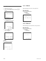
Laser Diode Properties
Wavelength :
403 to 410 nm
Emission duration : Continuous
Laser output power : 65 mW (max. of pulse peak),
35 mW (max. of CW)
GEFAHR
Bei geöffnetem Laufwerk und beschädigter oder
deaktivierter Verriegelung tritt ein unsichtbarer
Laserstrahl aus. Direkter Kontakt mit dem
Laserstrahl ist unbedingt zu vermeiden.
CAUTION
Use of controls or adjustments or performance of
procedures other than those specified herein
may result in hazardous radiation exposure.
Voor de klanten in Nederland
Gooi de batterij niet weg maar lever deze in als klein
chemisch afval (KCA).
CAUTION
The use of optical instruments with this product
will increase eye hazard.
Für Kunden in Deutschland
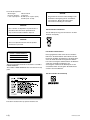
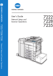
CLASS 1 LASER PRODUCT
LASER KLASSE 1 PRODUKT
LUOKAN 1 LASERLAITE
KLASS 1 LASER APPARAT
This Professional Disc Recorder is classified as a CLASS 1
LASER PRODUCT.
The CLASS 1 LASER PRODUCT label is located on the top
panel.
Entsorgungshinweis: Bitte werfen Sie nur entladene
Batterien in die Sammelboxen beim Handel oder den
Kommunen. Entladen sind Batterien in der Regel dann,
wenn das Gerät abschaltet und signalisiert “Batterie
leer” oder nach längerer Gebrauchsdauer der Batterien
“nicht mehr einwandfrei funktioniert”. Um
sicherzugehen, kleben Sie die Batteriepole z.B. mit
einem Klebestreifen ab oder geben Sie die Batterien
einzeln in einen Plastikbeutel.
For the customers in Taiwan only
This label is located on the top panel of the drive unit.
2 (P)
PDW-F70/F30/70MD
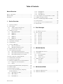
Table of Contents
Manual Structure
Purpose of this manual ................................................................. 4
1-17-4.
1-17-5.
1-17-6.
KY-580 Board ..................................................... 1-25
SE-800 Board ...................................................... 1-25
ADC-50S Board .................................................. 1-25
Related manuals ........................................................................... 4
1-18. Connecting/Disconnecting the Flexible Card Wire ...... 1-26
Trademarks ................................................................................... 4
1-19. i.LINK Controlling Command ...................................... 1-28
1-20. Notes on Handling Optical Block Assembly ................ 1-29
1-21. Unleaded Solder ............................................................ 1-30
1. Service Overview
1-22. Precautions for use of Condensation Sensor ................ 1-30
1-23. Memory Stick ............................................................... 1-31
1-1.
Operating Conditions ...................................................... 1-1
1-2. Power Supply .................................................................. 1-1
1-2-1.
Voltage and Power Requirements ......................... 1-1
1-2-2.
Recommeded Power Cord ..................................... 1-2
1-3. Supplied Accessories ...................................................... 1-3
1-3-1.
PDW-F70/F30/70MD ............................................ 1-3
1-3-2.
PDBK-101 ............................................................. 1-3
1-3-3.
PDBK-102 ............................................................. 1-3
1-3-4.
PDBK-103 ............................................................. 1-3
1-3-5.
PDBK-104 ............................................................. 1-3
1-4.
Matching Connectors and Cables ................................... 1-4
1-5.
Signal Inputs and Outputs ............................................... 1-5
1-6.
Circuit Function .............................................................. 1-8
1-7. Location of Main Parts ................................................... 1-9
1-7-1.
Printed Circuit Boards ........................................... 1-9
1-7-2.
Main Mechanical Part Locations ......................... 1-10
1-8.
Function and Location of Sensors ................................ 1-11
1-9. Removing/Reattaching Cabinet .................................... 1-12
1-9-1.
Removing/Reattaching Top Panel ....................... 1-12
1-9-2.
Removing/Reattaching Front Panel Assembly ... 1-12
1-9-3.
Removing/Reattaching Connector Panel ............ 1-13
1-10. How to Take Out a Cartridge Manually ....................... 1-13
1-11. Switch Settings on the Boards ...................................... 1-14
1-12. Circuit-Protection Part List ........................................... 1-17
1-13. Equipment and Fixtures List for Check/Adjustment .... 1-18
1-13-1. Equipment for Check/Adjustment ....................... 1-18
1-13-2. Fixtures ................................................................ 1-19
2. Error Messages
2-1.
Error Messages Overview ............................................... 2-1
2-2. Error Code List ............................................................... 2-2
2-2-1.
Error 0X ................................................................. 2-3
2-2-2.
Error 20 ................................................................. 2-4
2-2-3.
Error 3X ................................................................. 2-5
2-2-4.
Error 5X ................................................................. 2-5
2-2-5.
Error 6X ................................................................. 2-6
2-2-6.
Error 91 ................................................................. 2-7
2-2-7.
Error 92 ................................................................. 2-7
2-2-8.
Error 95 ................................................................. 2-8
3. XDCAM Web Site
3-1.
XDCAM Web Site Overview ......................................... 3-1
3-2. Status Menu .................................................................... 3-2
3-2-1.
Device Information ............................................... 3-2
3-2-2.
Hours Meter ........................................................... 3-3
3-2-3.
Software Version ................................................... 3-4
3-3. Maintenance Menu ......................................................... 3-6
3-3-1.
Download .............................................................. 3-6
3-3-2.
Account ............................................................... 3-10
3-3-3.
Network ............................................................... 3-11
1-14. Replacing NV-RAM and Memory Backup Battery ..... 1-20
1-15. Firmware Update .......................................................... 1-22
4. Maintenance Mode
1-16. Internal Video Test Signal ............................................ 1-23
1-17. Service Action After Replacing or Repairing
the Block and Board. .................................................... 1-25
1-17-1. Optical Block Assembly ...................................... 1-25
1-17-2. DPR-270 Board ................................................... 1-25
1-17-3. DR-550G Board .................................................. 1-25
PDW-F70/F30/70MD
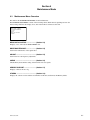
4-1.
Maintenance Menu Overview ......................................... 4-1
4-2.
Maintenance Menu List .................................................. 4-3
1
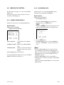
4-3. MENU DATA CONTROL ............................................. 4-5
4-3-1.
MENU STATUS DISPLAY ................................. 4-5
4-3-2.
SAVE MENU DATA ............................................ 4-5
4-3-3.
LOAD MENU DATA ........................................... 4-6
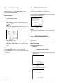
4-4. DRIVE MAINTENANCE .............................................. 4-6
4-4-1.
TEMPERATURE SENSOR ................................. 4-6
4-4-2.
DEW SENSOR ..................................................... 4-7
4-4-3.
FAN MOTOR ....................................................... 4-7
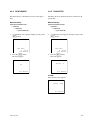
4-4-4.
ACCELERATION SENSOR ................................ 4-8
4-4-5.
LOADER ............................................................... 4-9
4-4-6.
AUTO TEST ....................................................... 4-11
4-4-7.
4-4-8.
4-4-9.
4-4-10.
4-4-11.
4-4-12.
4-4-13.
4-4-14.
4-4-15.
4-4-16.
4-4-17.
4-4-18.
4-4-19.
4-4-20.
4-4-21.
4-4-22.
4-4-23.
4-4-24.
4-4-25.
4-4-26.
4-4-27.
IN-LIM TEST ..................................................... 4-12
OUT-LIM TEST ................................................. 4-12
SPINDLE MOTOR ............................................. 4-13
FOCUS ACTUATOR ......................................... 4-14
TRACKING ACTUATOR ................................. 4-14
EXPANDER MOTOR ........................................ 4-15
SKEW SENSOR ................................................. 4-15
LASER ................................................................ 4-16
LC SHUTTER ..................................................... 4-16
LENS CLEANING ............................................. 4-17
SET OPTICAL DATA ........................................ 4-17
INITIALIZE SE .................................................. 4-18
SERVO_1 ............................................................ 4-19
MECHA RD ........................................................ 4-20
SERVO_2 ............................................................ 4-21
ACCELERATION OFFSET ............................... 4-22
ERROR LOGGER .............................................. 4-23
VERSION ............................................................ 4-24
SERIAL NO ........................................................ 4-24
CLEAR MEDIA LOG ........................................ 4-25
UPLOAD TO EEPROM ..................................... 4-25
4-5. ADJUST ....................................................................... 4-26
4-5-1.
VIDEO ................................................................ 4-26
4-6. CHECK ......................................................................... 4-26
4-6-1.
AUDIO TST SG .................................................. 4-26
4-6-2.
KEYBOARD CHECK ........................................ 4-27
4-7. SERVICE SUPPORT ................................................... 4-27
4-7-1.
ERROR LOG ...................................................... 4-27
4-7-2.
DIAGNOSTICS CONTROL .............................. 4-28
4-8. OTHERS ....................................................................... 4-28
4-8-1.
SOFTWARE VERSION ..................................... 4-28
4-8-2.
SERIAL NUMBER ............................................. 4-29
4-8-3.
MS FORMAT ..................................................... 4-30
2
5. Periodic Check and Maintenance
5-1. Periodic Maintenance ..................................................... 5-1
5-1-1.
Index ...................................................................... 5-1
5-1-2.
Digital Hours Meter .............................................. 5-2
5-1-3.
Periodic Check/Replacement Parts List ................ 5-2
5-2. Cleaning .......................................................................... 5-3
5-2-1.
General Information for the Use of Cleaning
Cloth ...................................................................... 5-3
5-2-2.
Cleaning Loader (P1) Assembly ........................... 5-3
5-2-3.
Cleaning Drive (P10) Sub Assembly .................... 5-4
5-2-4.
Cleaning Pickup Lens ............................................ 5-4
6. Replacement of Main Parts
6-1. General Information for Parts Replacement ................... 6-1
6-1-1.
Index ...................................................................... 6-1
6-1-2.
Basic Knowledge ................................................... 6-2
6-2.
Removing/Reattaching Power Supply Unit .................... 6-3
6-3.
Removing/Reattaching Upper Lid Assembly and
Shutter Assembly ............................................................ 6-4
6-4.
Replacing Drive (P10) Assembly ................................... 6-8
6-5.
Replacing Loader (P1) Assembly ................................. 6-12
6-6.
Replacing Cleaner (P1) Assembly ................................ 6-15
6-7.
Replacing Loading Motor (P1) Assembly .................... 6-16
6-8.
Removing/Reattaching Drive (P10) Sub Assembly ..... 6-18
6-9.
Removing/Reattaching Sled Rack Assembly ............... 6-21
6-10. Replacing Optical Block Assembly .............................. 6-23
6-11. Replacing No.2/No.3 Gear Assemblies ........................ 6-28
6-12. Replacing Seek Motor (P10) Assembly ....................... 6-31
6-13. Replacing Spindle Motor .............................................. 6-32
6-14. Replacing Cushion ........................................................ 6-34
6-15. Replacing Fan Motor .................................................... 6-35
6-15-1. Replacing Fan Motor (Drive) .............................. 6-35
6-15-2. Replacing Fan Motor (Side) ................................ 6-36
6-16. Replacing LCD Backlight ............................................. 6-37
6-17. Removing/Reattaching Mounted Circuit Boards .......... 6-38
6-17-1. APR-75/A Board ................................................. 6-38
6-17-2. AU-301/A Board ................................................. 6-39
6-17-3. DPR-270/A Board ............................................... 6-40
6-17-4. DR-550G Board .................................................. 6-41
6-17-5. EM-5 Board ......................................................... 6-44
6-17-6. ENC-101 Board ................................................... 6-44
6-17-7. HN-300G Board .................................................. 6-45
PDW-F70/F30/70MD
6-17-8.
6-17-9.
6-17-10.
6-17-11.
6-17-12.
6-17-13.
6-17-14.
6-17-15.
HP-130 Board ...................................................... 6-47
KY-580/A/B Board ............................................. 6-48
MS-80 Board ....................................................... 6-49
RX-93A/B Board ................................................. 6-49
SE-709 Board ...................................................... 6-50
SE-800 Board ...................................................... 6-51
SW-1124G Board ................................................ 6-52
VP-60/A Board .................................................... 6-53
7. Optical Drive Alignment
7-1. Optical Block Mechanical Alignment ............................ 7-1
7-1-1.
How to Move Optical Block Assembly ................ 7-1
7-1-2.
Calibrating Triangle Plates .................................... 7-2
7-1-3.
Adjustments After Replacing Optical Block
Assembly ............................................................... 7-3
7-1-4.
Skew Adjustment ................................................ 7-15
7-1-5.
RD Adjustment .................................................... 7-23
8. Electrical Alignment
8-1. Electrical Alignment Overview ...................................... 8-1
8-1-1.
Precautions ............................................................ 8-1
8-1-2.
Tools/Fixtures ........................................................ 8-1
8-1-3.
Displaying the Adjustment Item ........................... 8-1
8-2.
HD Free-Running Frequency Adjustment ...................... 8-1
8-3.
SD Free-Running Frequency Adjustment
(PDW-F70/70MD only) .................................................. 8-2
8-4.
SDI ENC Free-Running Frequency Adjustment
(PDW-F70/70MD only) .................................................. 8-3
8-5.
SDI DEC Free-Running Frequency Adjustment
(PDBK-104 is installed only) ......................................... 8-3
8-6.
LCD VCO Adjustment ................................................... 8-4
PDW-F70/F30/70MD
3
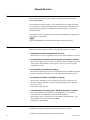
Manual Structure
Purpose of this manual
This manual is the Service manual volume 1 of the Professional Disc Recorder
PDW-F70/F30/70MD.
This maintenance manual (Volume 1, 2) is intended for use by trained system and
service engineers, and provides the information of maintenance and detailed service
(parts replacement, guideline for adjustment, schematic diagrams, board layouts,
detailed parts list).
This manual (volume 1) explains about maintenance information, parts replacement,
and guideline for adjustment.
n
Figures for PDW-F70 are used in this manual unless otherwise specified.
Related manuals
Besides this “Service manual Volume 1”, the following manuals are available.
. Operating lnstructions (Supplied with this unit.)
This manual is necessary for application and operation (and installation) of this unit.
. Protocol Manual of Remote (9-pin) Connector (Available on request)
This manual explains the protocol for controlling the VTR via the RS-422A (9-pin
serial remote). If this manual is required, please contact your local Sony Sales
Office/Service Center.
. Protocol Manual (Available on request)
This manual explains the protocol for controlling the VTR via the RS-232C. If this
manual is required, please contact your local Sony Sales Office/Service Center.
. Service Manual Volume 2 (Available on request)
This manual is intended for use by trained system and service engineers, and
describes schematic diagrams, board layouts and detailed parts list required for
parts-level service.
Part number: 9-968-228-XX
. “Semiconductor Pin Assignments” CD-ROM (Available on request)
This “Semiconductor Pin Assignments” CD-ROM allows you to search for
semiconductors used in Broadcast and Professional equipment.
This manual contains a complete list of semiconductors and their ID Nos., and
thus should be used together with the CD-ROM.
Part number: 9-968-546-XX
Trademarks
Trademarks and registered trademarks used in this manual are follows.
. Ethernet is a registered trademark of Xerox Corporation.
4
PDW-F70/F30/70MD
Section 1
Service Overview
1-1. Operating Conditions
1-2. Power Supply
c
Good air circulation is essential to prevent internal heat
build-up. Place the unit in location with sufficient air
circulation.
Do not block the ventilation holes of the cabinet and the
front and rear panels.
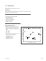
1-2-1. Voltage and Power Requirements
Operating temperature: 5 dC to 40 dC
Operating humidity:
25 % to 80 % (non-condensing)
Storage temperature:
_20 dC to 60 dC
Locations to avoid:
. Areas where the unit will be exposed to direct sunlight
of any other strong lights.
. Areas near heat sources.
. Dusty areas or areas subject to vibration.
. Areas with strong magnetic field.
. Areas with much electrical noise.
. Areas with much static electricity.
. Areas that is impossible to find a specified room for
installation.
. Areas windtight.
Tilt allowance:
Within 30d (Do not slant the front
and rear of the unit more than 30d.)
c
Fix the unit securely to avoid drop when the unit is operated at not-horizontal place.
Power voltage:
Power frequency:
Power consumption:
Rush current:
PDW-F70/F30/70MD
This unit’s power line has a switching regulator.
c
Be sure to operate the unit within the range of following
power voltage.
AC 100 to 240 V ± 10 %
50 Hz or 60 Hz
70 W
15 A (power voltage 100 V)
45 A (power voltage 240 V)
n
AC power supply is required a capacity which is commensurate with rush current.
If the capacity of the AC power supply is not enough, the
breaker of AC power of a supply side may operate or this
unit may not operate normally.
1-1
1-2-2. Recommeded Power Cord
This unit does not come with a power cord.
To get a power cord, please contact your local Sony Sales
Office/Service Center.
w
. Use the approved Power Cord (3-core mains lead)/
Appliance Connector/Plug with earthing-contacts that
conforms to the safety regulations of each country if
applicable.
. Use the Power Cord (3-core mains lead)/Appliance
Connector/Plug conforming to the proper ratings (Voltage, Ampere).
For customers in European countries except the United
Kingdom:
1 Power cord 250 V 10 A (2.0 m):
! 1-551-631-61
1
For customers in the China:
1 Power cord 250 V 10 A (1.8 m):
1
AC inlet
! 1-783-481-42
AC inlet
If you have questions on the use of the above Power Cord/
Appliance Connector/Plug, please contact your local Sony
Sales Office/Service Center.
w
. Never use an injured power cord.
If the unit is used in the area except above, please contact
your local Sony Sales Office/Service Center.
For customers in the U.S.A. and Canada:
1 Power cord 125 V 10 A (2.4 m):
! 1-551-812-41
(PDW-F70/F30)
1 Power cord 125 V 13 A (2.4 m):
! 1-556-813-31
(PDW-70MD)
1
For customers in United Kingdom:
1 Power cord 250 V 10 A (2.0 m):
1
1-2
AC inlet
! 1-777-823-12
AC inlet
PDW-F70/F30/70MD
1-3. Supplied Accessories
1-3-1. PDW-F70/F30/70MD
.
.
.
.
Vertical installation stand ............................................... 2
Infrared remote commander ........................................... 1
Ferrite core (PDW-F70/70MD) ..................................... 1
Operating instructions
Japanese version ....................................................... 1
English version ......................................................... 1
CD-ROM manual (PDW-F70/F30) .......................... 1
or CD-ROM manual (PDW-70MD) ......................... 1
. Proxy Browsing Software PDZ-1 .................................. 1
. Warranty booklet ............................................................ 1
. Sales companies guide (PDW-70MD) ........................... 1
1-3-2. PDBK-101
. Screw PSW3 x 8 ............................................................ 3
. Installation instructions .................................................. 1
1-3-3. PDBK-102
. Screw PSW3 x 8 ............................................................ 4
. Installation instructions .................................................. 1
1-3-4. PDBK-103
. Option panel assembly ................................................... 1
. Coaxial cable .................................................................. 4
. Screw
B3 x 5 ....................................................................... 4
PSW3 x 8 ................................................................. 4
. Installation instructions .................................................. 1
1-3-5. PDBK-104
. Option panel assembly ................................................... 1
. Coaxial cable .................................................................. 2
. Screw
B3 x 5 ....................................................................... 4
PSW3 x 8 ................................................................. 4
. Installation instructions .................................................. 1
PDW-F70/F30/70MD
1-3
1-4. Matching Connectors and Cables
When external cables are connected to the connector of this unit, the hardware listed below (or equivalents) must be used.
Panel indication
Matching connector (cable)
Name
Sony part No.
REF VIDEO INPUT
COMPOSITE INPUT (OPTION)
COMPOSITE OUT
SDSDI OUTPUT
DIGITAL AUDIO (AES/EBU)
TIME CODE
HD INPUT (OPTION)
SDSDI INPUT (OPTION)
BNC
*1
1-569-370-12
HD SDI INPUT
HD SDI OUTPUT
BNC *2
1-569-370-12
MONITOR
D-sub 15P
—
COMPOSITE OUT
AUDIO MONITOR
pin plug
—
AUDIO INPUT
XLR 3P, MALE
1-508-084-00
AUDIO OUTPUT
XLR 3P, FEMALE
1-508-083-00
CONTROL
mini plug
—
RS232C
D-sub 9P, FEMALE
REMOTE (9P)
9P remote control cable
(RCC-G series)
or
D-sub 9P, MALE or
JUNCTION SHELL 9P
(NETWORK)
(OPTION)
S400 (i.LINK)
PHONES *3
RJ-45 8P
1000BASE-T standard conformity article
(UTP cable is recommended. (UTP: Unshielded
Twist Pair))
—
1-569-370-12
1-561-749-00
—
IEEE1394 6P
VMC-IL6615B (1.5 m)
VMC-IL6635B (3.5 m)
—
—
JM-60 stereo phone plug
—
*1: It is recommended to connect the BELDEN 8281 cable or equivalent to this connector.
*2: It is recommended to connect the BELDEN 1694A cable or equivalent to this connector.
*3: It is in the front panel.
1-4
PDW-F70/F30/70MD
1-5. Signal Inputs and Outputs
Input (PDW-F70/70MD only)
HD SDI INPUT: BNC x 1
HD serial digital interface
SMPTE 292M
REF VIDEO INPUT: BNC x 2 (Loop through output)
External reference video signal
HD tri-level sync, or SD composite sync (0.3 V p-p,
75 Z, sync negative)
HD COMPONENT VIDEO INPUT: BNC x 4
(Option PDBK-103 is installed)
Analog HD (1080) component video
SMPTE 274M
Y/G, Pb/B, Pr/R: 0.7 V p-p, 75 Z
SYNC:
HD tri-level sync, or External
composite sync
0.6 V p-p, 75 Z
SD SDI INPUT: BNC x 1
(Option PDBK-104 is installed)
SD seirial degital interface
SMPTE 292M
COMPOSITE INPUT: BNC x 1
(Option PDBK-104 is installed)
Analog composite video
1.0 V p-p, 75 Z, negative
AUDIO INPUT CH-1/CH-3, CH-2/CH-4:
XLR 3-pin (Female x 2)
Analog audio
+4/0/_3/_6 dBu (Selectable), 10 kZ, balanced
DIGITAL AUDIO (AES/EBU) INPUT CH-1/CH-2, CH-3/
CH-4: BNC x 2
AES/EBU digital audio
AES-3id-1995
Output
HD SDI OUTPUT: BNC x 2
(PDW-F70/70MD only)
HD serial digital interface
SMPTE 292M
SD SDI OUTPUT: BNC x 1
(PDW-F70/70MD only)
SD serial digital interface
SMPTE 259M
COMPOSITE OUT: BNC x 1, RCA pin jack x 1
Analog composite video
1.0 V p-p, 75 Z, sync negative
AUDIO OUTPUT CH-1/CH-3, CH-2/CH-4:
XLR 3-pin (Male x 2)
Analog audio
+4/0/_3/_6 dBu (Selectable), 600 Z, balanced
AUDIO MONITOR: Pin jack x 2
Analog audio
_∞ to +1 dBu, 47 kZ, unbalanced, L/R/L + R Selectable
PHONES: Stereo standard jack x 1
Analog audio
_∞ to _14 dBu, 8 Z, unbalanced
DIGITAL AUDIO (AES/EBU) OUTPUT CH-1/CH-2,
CH-3/CH-4: BNC x 2
(PDW-F70/70MD only)
AES/EBU digital audio
AES-3id-1995
TIME CODE OUT: BNC x 1
(PDW-F70/70MD only)
SMPTE time cede
2.2 V p-p ± 3.0 dB, 600 Z, unbalanced
TIME CODE IN: BNC x 1
SMPTE time cede
0.5 to 18 V p-p, 3.3 kZ, unbalanced
PDW-F70/F30/70MD
1-5
MONITOR OUT: D-sub 15-pin (Female)
5
1
10
6
15
11
(External view)
NETWORK: RJ-45 8-pin modular jack
(Option PDBK-104 is installed)
10BASE-T (Conform to IEEE802.3i)
100BASE-TX (Conform to IEEE802.3u)
1000BASE-T (Conform to IEEE802.3ab)
8
Pin No.
Signal
1
R_VIDEO, R-Y_VIDEO
2
G_VIDEO, Y_VIDEO
3
B_VIDEO, B-Y_VIDEO
4
GND
5
GND
6
R_RET(G)
7
G_RET(G)
8
B_RET(G)
9
NC
10
SYNC_RET (GND)
11
GND
12
NC
13
H_SYNC
14
V_SYNC
15
NC
1
(External view)
Pin No.
Signal
1
BI DA+ (Input/Output)
2
BI DA_ (Input/Output)
3
BI DB+ (Input/Output)
4
BI DC+ (Input/Output)
5
BI DC_ (Input/Output)
6
BI DB_ (Input/Output)
7
BI DD+ (Input/Output)
8
BI DD_ (Input/Output)
REMOTE (9P): D-sub 9-pin (Female)
RS-422A
5
Control
S400 (i.LINK): 6-pin x 1
IEEE1394
CONTROL : Mini-jack 4-pole x 1
(PDW-F70/70MD only)
For remote control unit RM-LG2
1-6
1
9
6
(External view)
Pin No.
Signal
1
GND
2
RM_TX_(_) (Output)
3
RM_RX_(+) (Input)
4
GND
5
PRIORITY (Input/Output)
6
GND
7
RM_TX_(+) (Output)
8
RM_RX_(_) (Input)
9
GND
PDW-F70/F30/70MD
RS232C: D-sub 9-pin (Male)
1
5
6
9
(External view)
Pin No.
Signal
1
DCD: Data Carrier Detect (Input)
2
RX: Received Data (Input)
3
TX: Transmitted Data (Output)
4
DTR: Data Terminal Ready (Output)
5
SG: Signal Ground
6
DSR: Data Set Ready (Input)
7
RTS: Request to Send (Output)
8
CTS: Clear to Send (Input)
9
NC
PDW-F70/F30/70MD
1-7
1-6. Circuit Function
System configuration
Board name
Circuit function
Location No.
Digital process
DPR-270/A
Audio/Video/Core process/Host
8
and
ENC-101
MPEG encode
9
Video process
VP-60/A
REF/Composite/TC/AES I/O
5
Audio process
APR-75/A
Audio process
3
AU-301/A
Analog audio I/O
4
HP-130
Headphone connector
!=
HDSDI module
RX-93A/B
HDSDI module
6
Control panel
KY-580/A/B
Control panel (LCD/SW/JOG/SHUTTLE)
!-
Other
EM-5
Electric double layer cap
1
MS-80
Memory stick connector
2
Drive unit/
DR-550G
Drive main board
!/
Sensor
HN-300G
Mecha sensor connection board
![
SE-709
Loading position sensor board
!'
SE-800
Acceleration sensor board
!\
SW-1124G
Cartridge sensor SW board
!]
SW-1125G
Cartridge sensor SW board
!;
Power supply
PS-688
Power supply (AC/DC)
!,
Option
ADC-50 (PDBK-103)
Analog HD input
7
ADC-50S (PDBK-104)
SD input upconverter
7
NET-1 (PDBK-101)
Network
!.
TSI-54 (PDBK-102)
TS input/output
7
1-8
PDW-F70/F30/70MD
1-7. Location of Main Parts
1-7-1. Printed Circuit Boards
ADC-50 (PDBK-103) ........
ADC-50S (PDBK-104) .....
APR-75/A ..........................
AU-301/A ..........................
DPR-270/A ........................
DR-550G ...........................
EM-5 ..................................
ENC-101 ............................
HN-300G ...........................
HP-130 ...............................
KY-580/A/B ......................
MS-80 ................................
NET-1 (PDBK-101) ..........
PS-688 ...............................
RX-93A/B ..........................
SE-709 ...............................
SE-800 ...............................
SW-1124G .........................
SW-1125G .........................
TSI-54 (PDBK-102) ..........
VP-60/A .............................
7
7
3
4
8
!/
1
9
![
!=
!2
!.
!,
6
!'
!\
!]
!;
7
5
3
2
!,
4
!.
5
1
6
!=
7
!9
8
0
!\
![
!]
<Drive top view>
!;
!'
<Loader top view>
PDW-F70/F30/70MD
1-9
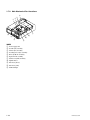
1-7-2. Main Mechanical Part Locations
0
9
3
2
1
!-
7
4
6
5
8
INDEX
1 Power supply unit
2 Loarder (P1) assembly
3 Cleaner (P1) assembly
4 Loarding motor (P1) assembly
5 Drive (P10) sub assembly
6 Optical block assembly
7 Seek motor (P10) assembly
8 Spindle motor
9 Fan motor (drive)
!/ Fan motor (side)
!- LCD backlight
1-10
PDW-F70/F30/70MD
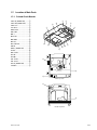
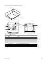
1-8. Function and Location of Sensors
Fan motor
1
(Adress: G-6/side A)
DPR-270 board
2 7
8
6
5
4
<Loder top view>
<Drive top view>
3
No.
Name
Function
1
Temperature sensor
IC3008 on the DPR-270 board, Control of the fan motor.
2
OP position sensor
Detects a position of the Optical block assembly.
3
REC INH sensor
Detects a status of the write-inhibited tab of a cartridge.
4
Cartridge down sensor
Detects the cartridge down.
5
Condensation sensor
Detects condensation.
6
Acceleration sensor
Detects acceleration added to the optical drive.
7
Cartridge in sensor
Loader position sensor
8
STBY OFF sensor
Loader position sensor
PDW-F70/F30/70MD
1-11
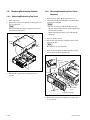
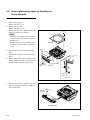
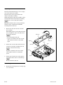
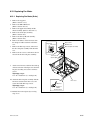
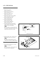
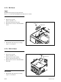
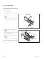
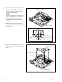
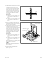
1-9. Removing/Reattaching Cabinet
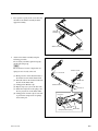
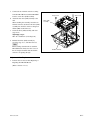
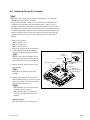
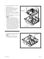
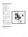
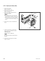
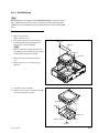
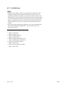
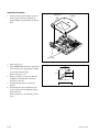
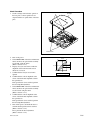
1-9-2. Removing/Reattaching Front Panel
Assembly
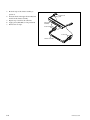
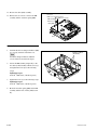
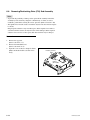
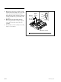
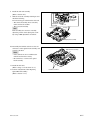
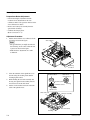
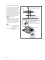
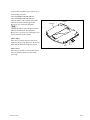
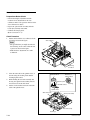
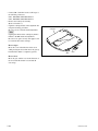
1-9-1. Removing/Reattaching Top Panel
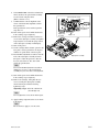
1. Turn off the unit.
2. Remove the seven screws and remove the top panel in
the arrow direction.
n
When reattaching the top panel, tighten the screws in
the numerical order below.
B3 x 5
1
Top panel
2
B3 x 5
3
4
5
B3 x 5
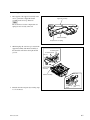
1. Remove the top panel. (Refer to Section 1-9-1.)
2. Disconnect the harness from CN113, and the flexible
card wire from CN106.
m
. Be very careful not to fold the flexible card wire.
The life of the flexible card wire will be significantly
shortened if it is folded.
. When connecting the harness, pass it through the
ferrite core.
3. Remove the three screws.
4. Release the claws from the round holes with a screwdriver or the like.
n
Be careful not to scratch the unit.
6
7
5. Remove the front panel assembly while disengaging
the notches from the rectangular holes.
Ferrite core
CN113
CN106
B3 x 5
3. Reinstall the top panel by reversing the steps of
removal.
B3 x 5
Round
hole
B3 x 5 Rectangular
holes
Claw
Notches
Front panel assembly
6. Reinstall the front panel assembly by reversing steps 1
to 5 of removal.
1-12
PDW-F70/F30/70MD
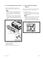
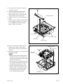
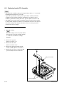
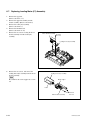
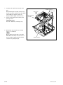
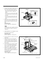
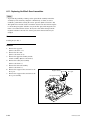
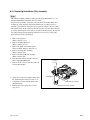
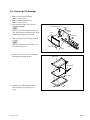
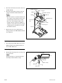
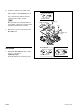
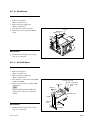
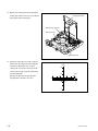
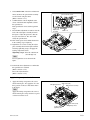
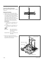
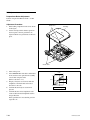
1-9-3. Removing/Reattaching Connector Panel
1. Remove the top panel. (Refer to Section 1-9-1.)
2. Remove the eight screws to detach the connector
panel.
m
. When the connector on PDW-F70MD is coverd,
remove the connector cover before removing the
connector panel.(Refer to the Operating Instructions.)
. Be careful not to detach the shield plate (i.LINK).
It the shield plate is detached, attach it while inserting portion A between the i.LINK connector and the
chassis.
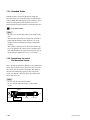
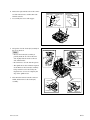
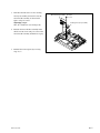
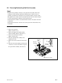
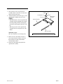
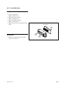
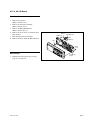
1-10. How to Take Out a Cartridge
Manually
If the unit cannot be powered on or the loader assembly
does not function, take out a cartridge as follows.
1. Turn the unit power off.
2. Turn the screw counterclockwise while pressing it
with a Phillips screwdriver (d = 2.2 mm or less) until
the cartridge is ejected.
m
. Turn the screw slowly and gently as for as it will go.
. After removing the cartridge, you do not need to
return the screw to its original position. Normal
operation will resume when the unit is powered on
again.
Screw
B3 x 5
B3 x 5
Claws
Connector panel
Rectangular
holes
B3 x 5
i.LINK connector
A
Shield plate (i.LINK)
3. Reattach the connector panel while fitting the claws
into the rectangular holes.
4. Tighten the eight screws.
5. Reattach the top panel. (Refer to Section 1-9-1.)
PDW-F70/F30/70MD
1-13
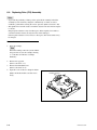
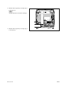
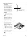
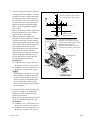
1-11. Switch Settings on the Boards
DPR-270 Board
m
Never change the setting of the factory use switches.
The number shown in the parentheses ( ) indicates the address on the circuit board.
1 A
B
C
D
E
F
G
H
J
K
L
M
N
P
R
2
3
4
5
6
7
8
S1900
9
S2102
S2101
S2100
10
S2103
11
DPR-270 board/Side A
Ref. No.
Bit
S1900 (L-9)
—
Description
Factory setting
Factory use
—
1, 2, 4, 7
Not used
OFF
3
Factory use
OFF
6
ON:
Starts only the OS and the
console.
OFF: Normal operation
OFF
8
ON:
Starts by the extarnal ROM
device.
OFF: Normal operation
OFF
S2100 (P-10)
Name
CPU SW
S2101 (P-8)
—
CPU SOFT RESET
Factory use
—
S2102 (R-8)
—
CPU POWER
Factory use
—
S2103 (P-10)
—
Model Select
PDW-F70
PDW-70MD
1-14
PDW-F70/F30/70MD
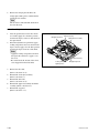
DR-550G Board
m
Never change the setting of the factory use switches.
The number shown in the parentheses ( ) indicates the address on the circuit board.
S600
1
S601
2
IC600
3
4
A
B
C
D
E
F
DR-550G board/Side A
Ref. No.
Bit
Name
Description
Factory setting
S600 (F-1)
—
System reset
Factory use
—
CPU operation
Factory use
S601 (F-2)
PDW-F70/F30/70MD
1, 3, 4
OFF
2
ON
1-15
NET-1 Board
m
Never change the setting of the factory use switches.
The number shown in the parentheses ( ) indicates the address on the circuit board.
A
B
C
D
E
F
G
H
1
2
3
S300
NET-1 board/Side A
Ref. No.
Bit
Name
Description
Factory setting
S300 (G-3)
—
LINUX SW1
—
—
1, 5 to 8
Factory use
OFF
2
ON: Starts by the extarnal ROM device.
OFF: Normal operation
OFF
3
ON: Starts mandatorily in normal mode.
OFF: Normal operation
OFF
4
ON: Starts mandatorily in recovery mode.
OFF: Normal operation
OFF
1-16
PDW-F70/F30/70MD
1-12. Circuit-Protection Part List
Circuit Protection Element
This unit is equipped with the positive characteristics
thermister(s) (power thermister) as the circuit protection
element. The positive characteristics thermister limits the
electric current flowing through the circuit as the internal
resistance increases when an exces-sive current flows or
when the ambient temperature increases.
If the positive characteristics thermister works, turn off the
main power of the unit and inspect the internal circuit of
this unit. After the cause of the fault is removed, turn on
the main power again. The unit works normally.
It takes about one minute to cool down the positive
characteristics thermister after the main power is turned
off.
Board
Ref. No. (Address)
Part No.
DR-550G
THP500 (F-4/Side B)
! 1-771-075-21
MS-80
THP1 (A-1/Side A)
! 1-803-353-21
Fuse/IC Link
w
The fuse and IC link are essential parts for safe operation.
Replace the components with Sony parts whose part
numbers appear in the manual published by Sony. If the
components are replaced with any parts other than the
specified ones, this may cause a fire or electric shock.
This unit is equipped with Fuse(s) and IC link(s).
An excessive current flows due to abnormality inside the
equipment, the fuse and/or IC link blow. If they blow, turn
off the main power of the equipment, inspect inside of the
equipment, and remove the cause of excessive current.
After that, replace the fuse and/or IC link.
Board
Ref. No. (Address)
Part No./Name
APR-75
F100 * (F-3/Side A)
! 1-576-800-11
Fuse 0.125 A, 250 V
F700 (A-2/Side A)
! 1-576-325-21
Fuse 0.16 A,125 V
F701(A-2/Side A)
! 1-576-325-21
Fuse 0.16 A,125 V
F3400 (H-1/Side A)
! 1-576-329-21
Fuse 10 A,125 V
F3401 (G-1/Side A)
! 1-576-329-21
Fuse 10 A,125 V
PS100 (C-3/Side B)
1-533-282-21
IC link 2 A,72 V
PS101 (C-3/Side B)
1-576-123-21
IC link 0.8 A,72 V
PS102 (C-3/Side B)
1-576-123-21
IC link 0.8 A,72 V
PS103 (C-3/Side B)
1-576-123-21
IC link 0.8 A,72 V
DPR-270
KY-580
*: PDW-F70/70MD only.
PDW-F70/F30/70MD
1-17
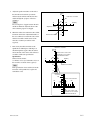
1-13. Equipment and Fixtures List for Check/Adjustment
1-13-1. Equipment for Check/Adjustment
It is recommended to use the equipment listed below or the equivalents.
Each equipment listed below is available as a standard product. However, it may not be producted now.
Equipment
Model name
Auto-collimator
Nikon 6D
Oscilloscope
Tektronix TDS3054B or
TDS460A
Frequency counter
Advantest TR5821
Regulated power supply
—
Output current: More than 10 A
Memory stick
—
For updating the software (Refer to Section 1-23.)
1-18
Remarks
PDW-F70/F30/70MD
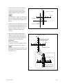
1-13-2. Fixtures
Fig. No.
Part No.
Description
Usage
1
J-6570-010-A
Triangle plates IN/OUT (PW-001)
Skew adjustment
2
J-6570-030-1
BRD-P1/P2 reflection block (PW-003)
3
J-6570-040-1
Calibration plate
—
J-6570-050-A
RD adjustment screwdriver (PW-005)
4
J-6570-060-A
KES-110A E&F LPF box
—
J-6570-110-A
Alignment disc (PFD23-RS)
Servo adjustment and RD adjustment
5
J-6325-110-A
Torque screwdriver’s bit (M1.4/M1.7)
Tightening screws
J-6325-380-A
Torque screwdriver’s bit (M2)
J-6323-430-A
Torque screwdriver’s bit (M3)
J-6325-400-A
Torque screwdriver (3 kg.cm) (0.3 N.m)
J-6252-510-A
Torque screwdriver (6 kg.cm) (0.6 N.m)
6
RD adjustment
Tightening screws
J-6252-520-A
Torque screwdriver (10 kg.cm) (1.0 N.m)
7
3-184-527-01
Cleaning cloth (15 cm x 15 cm)
Cleaning
—
3-703-358-08
Parallel pin (2 mm x 20 mm)
Gear replacement (one pin required)
8
7-432-114-11
Locking compound 200 g
Inhibits loosening of screws
—
7-640-010-89
Oil (LX-206)
Lubrication
—
7-651-000-10
Sony grease SGL-601 (50 g)
Lubrication
9
7-700-736-06
L-shaped hexagonal wrench (d = 0.89 mm)
Skew adjustment
0
9-919-573-01
Cleaning liquid
Cleaning
2
3
4
5
6
7
8
9
0
1
PW-001
OUT side
PW-001
IN side
d
PDW-F70/F30/70MD
1-19
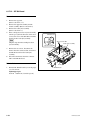
1-14. Replacing NV-RAM and Memory Backup Battery
(1) Overview
This unit is provided with a batter backed RAM and EEPROMs on the boards.
These memory devices store system setup data, adjustment data, and other data.
When any of these devices or the backup battery is replaced, the memory data must be rewritten.
Board
Ref. No.
Type
Stored data
DPR-270
IC2009
RAM
(with backup battery)
SYSTEM SEL setting data of setup menu
CLIP INFORMATION setting data
NUMERIC data of CLIP TITLE
Error log data
DPR-270
IC1902
EEPROM
Hours meter data
H1: OPERATION
Serial number data
TC PRESET value
TIME ZONE data
Free-running frequency adjustment value
HD f0, SD f0, SDI f0
Setup menu data
Menu bank 1-3 data
Menu backup data for SAVE MENU DATA in
MAINTENANCE MENU
DR-550G
IC603
EEPROM
Adjustment value of DRIVE MAINTENANCE menu
Hours meter data
H2: LASER PARAMETER
H3: SEEK RUNNING
H4: SPINDLE RUNNING
H5: LOADING COUNTER
KY-580
IC402
EEPROM
LCD VCO adjustment value
ADC-50S
IC115
EEPROM
Free-running frequency adjustment value
SDI DEC f0
NET-1
IC503
EEPROM
Control data
1-20
PDW-F70/F30/70MD
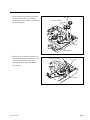
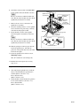
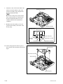
(2) Replacing Memory Backup Battery (IC2009/
DPR-270 board)
A crystal oscillator incorporating a backup battery is
attached to IC2009 on the DPR-270 board.
w
When replacing the part, be sure to use the specified one
below.
Use of an unspecified part may result in burst, fire or heating.
Replacement part
Model:
M4T28-BR12SH1
(lithium battery integrated crystal oscillator)
Part No.:
! 1-767-156-11
Recommended replacement cycle:
10 years
Replacement
n
When replacing the battery, install a new battery in correct
orientation of the mark.
1. Take note of the following setting data, if possible.
. SYSTEM SEL setting data of the setup menu
. CLIP INFORMATION setting data
. NUMERIC data of CLIP TITLE
. Error log data
n
Taking note of these data before replacement facilitates re-setting of menu data and other data after
replacement of the battery. However, no error log data
can be restored.
2. Turn off the power of the unit.
3. Remove the DPR-270 board. (Refer to Section 6-17-3.)
4. Insert a flat-blade screwdriver between the battery and
IC2009 and detach the battery.
Battery
Mark
5. Install a new battery matching its mark with the mark
on IC2009.
6. Install the DPR-270 board.
7. Turn on the power of the unit while pressing the
[MENU] and [RESET] buttons simultaneously.
When “ALL RESET” appears, release your fingers
from the keys.
8. Press the [SET] button.
n
Fixed values of the ROM is used for initialization data.
9. Restart the unit.
10. Perform the settings again using the data noted in step
1.
(3) Replacing NV-RAM (IC2009/DPR-270 board)
Replace IC2009, after detaching the battery. The other
replacement steps are the same as those in (2) Replacing
Memory Backup Battery (IC2009/DPR-270 board).
(4) Replacing EEPROM (IC1902/DPR-270 board)
n
Even if this EEPROM is replaced in the field, no data can
be initialized. When you need to replace this EEPROM,
contact your local Sony Sales Office/Service Center.
(5) Replacing EEPROM (IC603/DR-550G board)
1. Turn off the power of the unit, and then remove the
DR-550G board. (Refer to Section 6-17-4.)
2. Replace IC603 (D-1/side B).
3. Install the DR-550G board, and then turn on the power
of the unit.
4. Perform UPLOAD TO EEPROM of the MAINTENANCE MENU. (Refer to Section 4-4-27.)
(6) Replacing EEPROM (IC402/KY-580 board)
1. Turn off the power of the unit, and then remove the
KY-580 board. (Refer to Section 6-17-9.)
2. Replace IC402 (D-3/side A).
3. Install the KY-580 board, and then turn on the power
of the unit.
4. Perform LCD VCO adjustment. (Refer to Section 8-6.)
DPR-270 board
IC2009
(address: N-10)
Mark
Flat-blade screwdriver
PDW-F70/F30/70MD
1-21
(7) Replacing EEPROM (IC115/ADC-50S board)
1. Turn off the power of the unit, and then remove the
ADC-50S board. (Refer to the Installation Instructions
PDBK-104)
2. Replace IC115 (B-3/side A).
3. Install the ADC-50S board, and then turn on the power
of the unit.
4. Perform SDI DEC free-running frequency adjustment.
(Refer to Section 8-5.)
(8) Replacing EEPROM (IC503/NET-1 board)
n
Even if this EEPROM is replaced in the field, no data
canbe initialized. When you need to replace this EEPROM,
contact your local Sony Sales Office/Service Center.
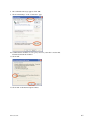
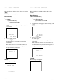
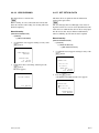
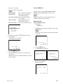
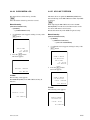
1-15. Firmware Update
This section describes how to update the firmware using
the MAINTENANCE MENU.
n
Update the firmware for the NET-1 borad on XDCAM
website, no using the MAINTENANCE MENU.
(Refer to Section 3.)
The following firmware programs and data are updated.
. CPU data (SYS) on the DPR-270 board
. ASIC (NOVA) setting data (NIOS, OSD) on the DPR270 board
. FPGA configuration data (GOTA, ZATA) on the DPR270 board
. DSP program data (DSP0-2, PRXV, PRXA, TMBP,
TSYS) on the DPR-270 board
. FPGA configuration data (HDRX) on the RX-93 board
. CPU data (KY) on the KY-580 board
. Drive firmware program (DRV)
. Firmware program (TS, TSIC) on the TSI-54 board
A Memory Stick containing the new version firmware
package file is required for the update.
For getting such firmware package file, contact your local
Sony Sales Office/Service Center.
Put the firmware package file in the /MSSONY/PRO/
XDCAM/PDWF70/ directory of the Memory Stick.
m
. To update the firmware programs (TS and TSIC) on the
TSI-54 board, another package file is required.
. It takes about 14 minutes to update the firmware and
another about four minutes to update the firmware on
the TSI-54 board.
. If the Memory Stick is removed during update, it may
become unavailable. Do not remove the Memory Stick
during update.
. The LCD screen is refreshed during update, but this is
not a problem.
1-22
PDW-F70/F30/70MD
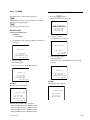
Execution Procedure
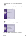
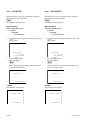
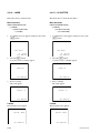
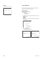
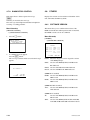
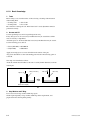
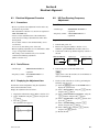
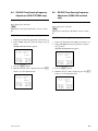
1-16. Internal Video Test Signal
1. Insert a Memory Stick containing the new version
firmware package file into the Memory Stick slot on
the rear panel.
2. Eject a remaining disc, if any.
3. Display the MAINTENANCE MENU.
(Refer to Section 4-1.)
4. Choose “OTHERS” with the [(]/[)] buttons, and then
press the [*] button.
5. Choose “SOFTWARE VERSION” with the [(]/[)]
buttons, and then press the [*] button.
6. Press the [SET] button while pressing the [SHIFT]
button.
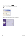
The PACKAGE UPDATE window opens.
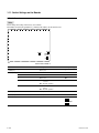
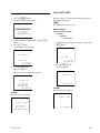
This unit has the internal video test signal generator.
The test signals output from the video test signal generator
can be recorded.
Perform the following steps to output the test signals.
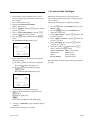
PACKAGE UPDATE
CURRENT
VERSION
1.00
-->
NEW
VERSION
1.01
VERSION UP OK?
UPDATE :
SET KEY
ABORT : RESET KEY
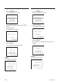
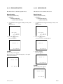
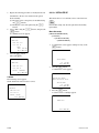
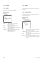
7. Update the firmware on the TSI-54 board using the
following procedure.
(1) Press the [)] button several times to display the
TS version in the time data display area.
(2) Press the [SET] button while pressing the
[SHIFT] button.
The PACKAGE UPDATE window opens.
1. Press the [F1] button on the HOME menu to set the V
INPUT to “SG”.
2. Press the [MENU] button on the HOME menu to
display the system menu.
3. Select “SETUP MENU” using the [(]/[)] buttons, and
press the [*] button.
4. Select “VIDEO CONTROL” using the [)] button, and
press the [*] button.
5. Select “INT VIDEO SG” using the [(]/[)] buttons,
and press the [*] button.
6. Select the test signal to be output using the [(]/[)]
buttons, and press the [SET] button.
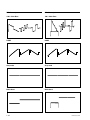
100% COLOR BARS: 100% color-bar signal
RAMP (Y/C):
RAMP signal
GRAY:
gray scale signal
BLACK BURST:
black burst signal
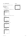
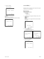
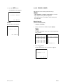
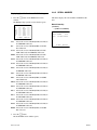
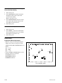
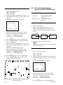
Describes output waveform figures of this generator in the
next page.
TS UPDATE
(PDBK-102)
CURRENT
VERSION
1.00
-->
NEW
VERSION
1.01
VERSION UP OK?
UPDATE :
SET KEY
ABORT : RESET KEY
(3) Perform step 8 and the following steps.
8. Check the update information, and then press the
[SET] button.
The firmware update starts.
n
Do not remove the Memory Stick during update.
9. A message “COMPLETE” appears when the update is
completed.
10. Turn off and on the power of the unit.
PDW-F70/F30/70MD
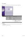
1-23
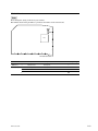
HD video outputs
SD video outputs
100% Color Bars
100% Color Bars
RAMP
RAMP
Gray scale
Gray scale
Black burst
Black burst
1-24
PDW-F70/F30/70MD
1-17. Service Action After Replacing or
Repairing the Block and Board.
1-17-1. Optical Block Assembly
After replacing the optical block assembly, perform the
following adjustments in descending order.
(Refer to Section 7-1-3.)
. Skew adjustment
. Optical Block Assembly Data Setting
. Laser Initial Data Setting
. Servo1 Automatic Adjustment
. RD adjustment
. Servo2 Automatic Adjustment
. Clear media log
1-17-2. DPR-270 Board
Perform the following re-settings after replacing or
repairing the DPR-270 board or after replacing the
NVRAM (IC2009).
Re-setting After Replacing the DPR-270 Board
Perform the re-settings after replacing the NVRAM and
following re-settings after the DPR-270 board is replaced.
. Onboard switch S2103 setting (PDW-70MD only; Refer
to Section 1-11.)
. Date and time “DATE/TIME PRESET” setting (Refer to
the Operating Instructions.)
. Time code preset number “TC PRESET” setting (Refer
to the Operating Instructions.)
. Setup menu setting (Refer to the Operating Instructions.)
. Menu bank 1 to 3 “SETUP BANK OPERATION”
setting (Refer to the Operating Instructions)
. Serial number setting
For more information, contact your local Sony Sales
Office/Service Center.
Re-setting After Replacing the NVRAM
. System setting “SYSTEM SEL” of the unit (Refer to the
Operating Instructions.)
. Clip information “CLIP INFORMATION” setting
(Refer to the Operating Instructions.)
. Clip title preset number “NUMERIC of CLIP AUTO
TITLING” setting (Refer to the Operating Instructions.)
. Function menu setting (Refer to the Operating Instructions.)
1-17-3. DR-550G Board
This board includes EEPROM (IC603) that stores adjustment data, hours meter data, and other data.
Replace IC603 after the DR-550G board is replaced.
Execute the drive maintenance menu in the following order
after replacing or repairing the DR-550G board.
1. SET OPTICAL DATA (Refer to Section 4-4-17.)
2. INITIALIZE SE (Refer to Section 4-4-18.)
3. ACCELERATION OFFSET (Refer to Section 4-4-22.)
4. SERVO_1 (Refer to Section 4-4-19.)
5. SERVO_2 (Refer to Section 4-4-21.)
6. CLEAR MEDIA LOG (Refer to Section 4-4-26.)
1-17-4. KY-580 Board
Perform the LCD VCO adjustment after repairing the KY580 board. (Refer to Section 8-6.)
1-17-5. SE-800 Board
Carry out “ACCELERATION OFFSET” of the maintenance menu after replacing the SE-800 board.
(Refer to Section 4-4-22.)
Adjustments After Repairing the DPR-270 Board
After the DPR-270 board is repaired, perform the following adjustments after the re-settings above.
. Perform the free-running frequency adjustment.
(Refer to Section 8.)
8-2. HD Free-Running Frequency Adjustment
8-3. SD Free-Running Frequency Adjustment (PDWF70/70MD only)
8-4. SDI ENC Free-Running Frequency Adjustment
(PDW-F70/70MD only)
PDW-F70/F30/70MD
1-17-6. ADC-50S Board
Perform the SDI DEC free-running frequency adjustment
after repairing the ADC-50S board. (Refer to Section 8-5.)
1-25
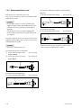
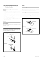
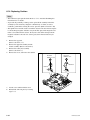
1-18. Connecting/Disconnecting the
Flexible Card Wire
Type B
This unit uses the four types of flexible card wires.
m
. Be very careful not to fold the flexible card wire. Life of
flexible card wire will be significantly shortened if it is
folded.
. The flexible card wire has the conduction side and the
insulation side. If the conduction side and the insulation
side are connected in the wrong direction, the circuit will
not function.
. Insert the flexible card wire straight.
. Ensure that the conduction surface of the flexible card
wire is not contaminated.
Open the latch of the connector in the direction of arrow B
to unlock, and disconnect the flexible card wire.
Disconnecting
Connecting
1. Insert the flexible card wire firmly as far as it will go,
with the conduction side up.
2. Close the latch of the connector in the direction of
arrow C to lock.
Disconnecting
Latch
Connector
Type A
Flexible card wire
B
Disconnecting
Slide portions A of the connector to unlock, and disconnect
the flexible card wire.
Connecting
Latch
Connecting
Connector C
Flexible card wire
Insert the flexible card wire firmly as far as it will go, and
push down portions A of the connector.
Conduction side
Disconnecting
Flexible card wire
Insulation side
A
Lock lever
Connector
A
Connecting
Flexible card wire
A
Connector
1-26
A
PDW-F70/F30/70MD
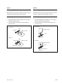
Type C
Type D
Disconnecting
Disconnecting
Open the latch of the connector in the direction of arrow D
to unlock, and disconnect the flexible card wire.
Open the latch of the connector in the direction of arrow F
to unlock, and disconnect the flexible card wire.
Connecting
Connecting
1. Insert the flexible card wire firmly as far as it will go,
with the insulation side up.
2. Close the latch of the connector in the direction of
arrow E to lock.
1. Insert the flexible card wire firmly as far as it will go,
with its conduction side facing front.
2. Close the latch of the connector in the direction of
arrow G to lock.
Disconnecting
Disconnecting
Latch
Flexible card wire
Connector
Flexible card wire
D
Latch
F
Connector
Connecting
Latch
Connector E
Flexible card wire
Connecting
Flexible card wire
Insulation side
G
Latch
Conduction side
Connector
PDW-F70/F30/70MD
1-27
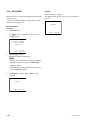
1-19. i.LINK Controlling Command
AV/C Command List
The following list shows AV/C command (Only VCR Subunit Command) of which are supported with
this unit.
AV/C command conform to 1394 TA Document AV/C Digital Interface Command Set General Specification/VCR Subunit Specification Version 2.0.1 Jan.5,1998.
AV/C command has the following three types.
. CONTROL Command : Control command
. STATUS Inquiry Command : Sense command
. SPECIFIC Inquiry Command : Inquiry command whether control command are supported or not.
* C and S of the Support shows the CONTROL Command and STATUS Command.
Support
Opecode
Value
ABSOLUTE TRACK NUMBER
52h
BINARY GROUP
5Ah
LOAD MEDIUM
C1h
MEDIUM INFO
DAh
Comments
C
S
O
O
Absolute Track Number search/sense command
O
Binary Group Data sense command
O
Eject command
O
Tape Information sense command
O
Output Signal Mode control command
OUTPUT SIGNAL MODE
78h
O
PLAY
C3h
O
Play/Search command
RECORD
C2h
O
Record command
RELATIVE TIME COUNTER
57h
O
SEARCH MODE
50h
O
COUNTER search/sense/preset command
O
Search Mode sense command
SMPTE/EBU TIME CODE
59h
O
O
Time Code search/sense command
TIME CODE
51h
O
O
Time Code search/sense command
TRANSPORT STATE
D0h
O
Tape transport sense command
WIND
C4h
1-28
O
STOP/FF/REW command
PDW-F70/F30/70MD
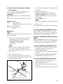
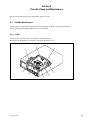
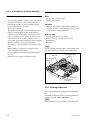
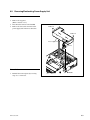
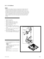
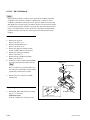
1-20. Notes on Handling Optical Block
Assembly
To prevent the damage due to the electrostatic charge, be
sure to put the following grounding while handling the
optical block assembly (KES-110A).
Grounding for the human body
Be sure to put on an antistatic band for grounding (with
impedance lower than 108 Z) whose other end is grounded.
n
Because static electricity charged on clothes is not drained
away, be careful not to touch your clothes to the optical
block assembly.
Grounding for the work table
Be sure to place the optical block assembly on an antistatic
mat (with impedance lower than 109 Z recommended) or a
copper sheet for grounding.
Precautions
. The optical block assembly is a precise unit. Be careful
not to subject it to shocks by dropping or rough handling.
. Do not touch the objective lens.
. Hold the slide base (die casting part) when handling the
optical block assembly.
Do not touch the circuit on the print board with your
hand or a substance directly; otherwise, the circuit may
be damaged.
. The performance of the actuator may be affected if a
magnetic material is located nearby, since the actuator
has a strong magnetic field.
Keep magnetic substance away from the actuator. if the
magnetic force makes a metallic material such as a
screwdriver, reflection block and so on hit the actuator,
the objective lens will be damaged.
. Do not allow foreign materials to enter through gap in
the cover of the actuator.
Antistatic band
Keep away a
screwdriver
Objective
lens
Optical block assembly
Actuator
Hold the shaded portions. (
)
Antistatic mat
PDW-F70/F30/70MD
1-29
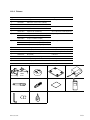
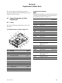
1-21. Unleaded Solder
Unleaded solder is used for all the boards of this unit.
Boards requiring use of unleaded solder are printed with a
lead free mark (LF) indicating the solder contains no lead.
(Caution: Some printed circuit boards may not come
printed with the lead free mark due to their particular size.)
: LEAD FREE MARK
m
. Be sure to use the unleaded solder for the boards of this
unit.
. The unleaded solder melts at a temperature about 40 dC
higher than the ordinary solder, therefore, it is recommended to use the soldering iron having a temperature
regulator.
. The ordinary soldering iron can be used but the iron tip
has to be applied to the solder joint for a slightly longer
time. The printed pattern (copper foil) may peel away if
the heated tip is applied for too long, so be careful.
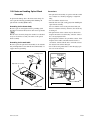
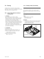
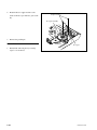
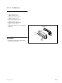
1-22. Precautions for use of
Condensation Sensor
Due to the foreign substances adhering to the condensation
sensor chip (see figure below), the sensor fails to measure
the correct value of residence to humidity. This prevents
the unit from functioning properly. If any foreign substance gets adhered to the chip, replace the condensation
sensor with a new one.
m
. Do not touch the chip with bare hands.
. Do not clean the chip with alcohol or other similar
agents.
Solders
1 pin
Bracket
1-30
Condensation
sensor chip
Leads
Connector
PDW-F70/F30/70MD
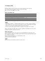
1-23. Memory Stick
The Memory Stick can be used to update software from the maintenance menu of the unit.
Insert a Memory Stick into the Memory Stick slot on the connector panel.
The 8, 16, 32, 64, and 128 MB types are avilable.
Memory Stick Media Table
Memory Stick
Yes
Memory Stick Duo
Yes
Memory Stick (MagicGate/Correspond to High-speed data transfer)
Yes (*1)
Memory Stick Duo (MagicGate/Correspond to High-speed data transfer)
Yes (*1)
MagicGate Memory Stick
Yes
MagicGate Memory Stick Duo
Yes
*1: This media does not correspond to MagicGate or high-speed data transfer.
m
. If the “Memory Stick Duo” or “MagicGate Memory Stick Duo” is used with a standard-size Memory
Stick compatible device, always insert it in the attached (or separately available) Memory Stick Media
Adaptor. If you insert directly, the Memory Stick media may not be removed.
. It does not guarantee entire operation of Memory Stick media. Some products are not available.
Memory Stick, Memory Stick PRO, Memory Stick Duo, and Memory Stick PRO Duo are the registered
trademarks or trademarks of the Sony Corporation.
Memory Stick format
Always format Memory Sticks to be used in this unit using MS FORMAT in the maintenance menu.
(Refer to Section 4-8-3.) Be sure to use Memory Stick Formatter on a PC provided with a Memory Stick
slot or a Memory Stick adapter.
Further create the following directory in a formatted Memory Stick.
/MSSONY/PRO/XDCAM/PDWF70/
n
Once formatting is executed, Memory Stick data is entirely cleared.
PDW-F70/F30/70MD
1-31
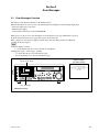
Section 2
Error Messages
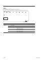
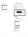
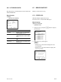
2-1. Error Messages Overview
This unit has a self diagnosis function to check internal errors.
When the unit detects an error, its error code and description are displayed on the following display units.
. Time data display (error code only)
. Monitor image display
. Video monitor connected to connector MONITOR
When an error occurs, its error code information is recorded in the error logger (maintenance logger) of
the main unit and also in the error logger (drive logger) of the drive unit.
Refer to respective error tables for display contents on the time data display and for recording/nonrecording in the error loggers.
n
“Time data display” column:
“←” means that the same error code as the left one is displayed.
“Maintenance logger”, “Drive logger” columns:
. “O” means that the error is recorded in the logger.
. “X” means that the error is not recorded in the logger.
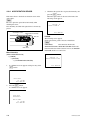
Sample of display
(on a video monitor)
Monitor image display
ERROR
ACCESS
1
0
0
-12
-12
-20
-20
-30
-40
-60
-30
-40
-60
2
3
TCG
EXT
MPEG HD
LOCAL
REMOTE
LEVEL
PHONES
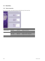
SP
VITC
1080 60I
COOO1
RUN MODE
REC RUN
F3
TC/VITC
VITC
F4
REM:077 M
DF/NDF
NDF
00: 00 .00: 00
CH-1
2 CH
F2
3 + 4
4
4CH 16 BIT
NETWORK
3 CH
AN ERROR HAS BEEN
DETECTED. INFORM SERVICE
OF FOLLOWING CODE:
XX-XXX
F1
TC MODE
PRESET
P2
CLIP
THUMB
NAIL
CLIP
MENU
ESSENCE
MARK
IN
SET
VCR
MARK1
MENU
F5
OUT
RESET
JOG
PAGE DISPLAY
4 CH
SHIFT
TOP
MARK2
NEXT
PLAY
PREV
VARIABLE
REC
PRESET
PB
F REV
F FWD
STOP
REC
SHUTTLE
END
Time data display
PDW-F70 (Front view)
PDW-F70/F30/70MD
2-1
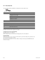
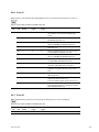
2-2. Error Code List
An error code is provided in combination of 2-digit main code and 3-digit sub code.
XX-XXX
Main code
Sub code
Main code
Main error description
0X
Optical drive control errors, device errors
. 02: Optical devices (LD, LCD)
. 03: Optical drive two-axis (FCS, TRK)
. 04: Optical drive seeking
. 06: Optical drive expander
. 08: Optical drive spindle
20
Loader (P1) assembly errors
3X
Optical drive sensor system errors
5X
Read data errors
6X
Startup errors
91
Interface errors between CPU and peripheral devices
92
Synchronization system errors
95
Video/audio signal processing device errors
For details of sub codes, refer to respective error tables.
If multiple errors occur simultaneously
The highest-priority error is displayed.
When a higher-priority error is cleared, the following-priority error code is displayed.
Protection Mode
When this unit detects an error, it enters a protection mode to prevent the cartridge disc, optical drive, and
other components from damage or failure.
The protection mode depends on error status. When a cartridge is inserted, press the EJECT button and
remove the cartridge.
2-2
PDW-F70/F30/70MD
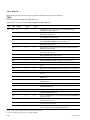
2-2-1. Error 0X
When errors related to optical drive control or to devices are detected, the following error codes are
displayed.
Main
code
Sub
code
Time data
display
Maintenance
logger
Drive
logger
Description
02
020
←
O
O
Optical block assembly (refer to as OP hereafter) is
recording at maximum laser output.
Perform the pickup lens cleaning.
(Refer to Section 4-4-16.)
X25
←
O
O
OP laser output error is detected.
X26
←
O
O
OP laser output coefficient cannot be adjusted.
X27
←
O
O
OP laser current is abnormal (zero or excessive).
X28
←
O
O
OP laser output is stopped judging that no cartridge is
inserted.
X31
←
O
O
OP LCD shutter does not open.
X54
←
O
O
No signal from disc required for OP focus servo can be
detected.
X57
←
O
O
No control current is detected in OP focus servo.
X58
←
O
O
Excessive control current is detected in OP focus servo.
X67
←
O
O
No control current is detected in OP tracking servo.
X68
←
O
O
Excessive control current is detected in OP tracking
servo.
060
←
X
O
OP is operating with tracking servo characteristics down.
X7C
←
O
O
OP cannot move to disc’s innermost circumference.
X7D
←
O
O
OP cannot move to disc’s outermost circumference.
E41
←
O
O
OP expander home position cannot be detected during
startup adjustment.
F41
←
O
O
OP expander home position cannot be detected during
power-on initialization.
091
←
O
O
Spindle motor does not rotate after the predetermined
time has passed (or no FG signal is detected).
095
←
O
O
Spindle motor cannot be stopped (or abnormal FG signal
is detected).
292
←
O
O
Spindle motor rotation is detected during vertical move of
loading. *
992
←
O
O
Spindle motor rotation is detected during vertical move of
unloading. *
03
04
06
08
* : The vertical move of loading/unloading is also carried out by STBY ON/OFF.
PDW-F70/F30/70MD
2-3
n
Any number of the following is applicable for “X” in the sub codes above, showing an operation status
where the error is detected.
Example) 827: Laser current of optical block assembly is abnormal (zero or excessive) “during horizontal
move of unloading”.
0:
1:
2:
3:
4:
5:
6:
7:
8:
9:
A:
B:
C, D:
E:
F:
Operation cannot be identified or no need to be identified.
During loading
During vertical move of loading
Disc is not rotating
Seeking
Reading
Writing
Standby state
During horizontal move of unloading
During vertical move of unloading
During disc removal
During lens cleaning or device checking
(Not used)
During startup adjustment of optical block assembly
During power-on initialization of optical block assembly expander
2-2-2. Error 20
When errors related to loader (P1) assembly are detected, the following error codes are displayed.
Main
code
Sub
code
Time data
display
Maintenance
logger
Drive
logger
Description
20
111
←
O
O
Horizontal move of loading did not end within the
predetermined time.
117
←
O
O
Displacement of cartridge is detected in the loader during
horizontal move of loading.
211
←
O
O
Vertical move of loading did not end within the predetermined time.
213
←
O
O
Cartridge cannot be detected after loading.
217
←
O
O
Displacement of cartridge is detected in the loader during
vertical move of loading.
811
←
O
O
Horizontal move of unloading did not end within the
predetermined time.
2-4
PDW-F70/F30/70MD
2-2-3. Error 3X
When errors related to the optical drive sensor system are detected, the following error codes are displayed.
Main
code
Sub
code
Time data
display
Maintenance
logger
Drive
logger
Description
34
500
←
O
O
Loader position sensor (SE-709 board) is detects
abnormal code.
35
500
ACC Sensor!
X
O
Abnormality of acceleration sensor is detected.
37
500
High TEMP!
X
O
Optical block assembly temperature sensor detects
abnormal status.
39
500
Skew Sensor
X
O
Abnormality of skew sensor in optical block assembly
is detected.
3A
500
Skew Sensor
X
O
Abnormality of skew sensor in optical block assembly
is detected.
3C
500
HUMID!
X
O
Dew condensation is detected.
2-2-4. Error 5X
When read data errors are detected, the following error codes are displayed.
Main
code
Sub
code
Time data
display
50
010
51
52
Drive
logger
Description
(Not displayed) X
O
BCA area data cannot be read.
011
(Not displayed) X
O
BCA area data is invalid.
020
DI read err
X
O
PIC area data cannot be read.
021
DI read err
X
O
PIC area data is invalid.
X0B
Read err
X
O
Address cannot be read from disc in optical block
assembly.
PDW-F70/F30/70MD
Maintenance
logger
2-5
n
Any number of the following is applicable for “X” in the sub codes above, showing an operation status
where the error is detected.
Example) 80B: Address cannot be read from the disc in optical block assembly “during horizontal move
of unloading”.
0:
1:
2:
3:
4:
5:
6:
7:
8:
9:
A:
B:
C, D:
E:
F:
Operation cannot be identified or no need to be identified.
During loading
During vertical move of loading
Disc is not rotating
Seeking
Reading
Writing
Standby state
During horizontal move of unloading
During vertical move of unloading
During disc removal
During lens cleaning or device checking
(Not used)
During startup adjustment of optical block assembly
During power-on initialization of optical block assembly expander
2-2-5. Error 6X
When errors related to startup operation are detected, the following error codes are displayed.
Main
code
Sub
code
Time data
display
60
E00
6F
E00
DRV ADJ err
2-6
Maintenance
logger
Drive
logger
Description
(Not displayed) X
O
Optical block assembly cannot seek to target position
during startup.
X
O
Optical block assembly startup adjustment cannot be
completed.
PDW-F70/F30/70MD
2-2-6. Error 91
When interface errors between CPU and peripheral devices are detected, the following error codes are
displayed.
n
System control CPU: IC1900 on the DPR-270 board
Main
code
Sub
code
Time data
display
Maintenance
logger
Drive
logger
Description
91
125
←
O
X
System control CPU detects interruption in communication with key control CPU (KY: IC501/KY-580
board).
130
←
O
X
System control CPU detects flash memory (IC1909,
IC1910/DPR-270 board) error.
139
←
O
X
System control CPU detects an error in setup menu
data area (EEPROM: IC1902/DPR-270 board).
13A
←
O
X
System control CPU detects NVRAM (IC2009/DPR270 board) error.
13B
←
O
X
System control CPU detects an error in hours meter
area (EEPROM: IC1902/DPR-270 board).
13C
←
O
X
System control CPU detects an error in adjustment
data area (EEPROM: IC1902/DPR-270 board).
13D
←
O
X
System control CPU detects an error in hours meter
area (EEPROM: IC1902/DPR-270 board).
155
←
O
X
Communication between system control CPU and
optical drive (DR-550G board) is interrupted.
215
←
X
X
Key control CPU (KY: IC501/KY-580 board) detects
interruption in communication with system control
CPU.
430
←
O
X
CPU (NET-1 board) detects flash memory (IC401/
NET-1 board) error. *
551
←
O
O
Optical drive’s system control CPU (DRV: IC600/DR550G board) detects firmware error.
Perform the firmware update. (Refer to Section 1-17.)
595
←
O
O
Optical drive’s system control CPU (IC600/DR-550G
board) detects interruption in communication with SV
DSP (IC400/DR-550G board).
* : This error message is displayed only when the PDBK-101 is installed.
2-2-7. Error 92
When synchronization system errors are detected, the following error codes are displayed.
n
System control CPU: IC1900 on the DPR-270 board
Main
code
Sub
code
Time data
display
Maintenance
logger
Drive
logger
Description
92
101
←
O
X
System control CPU detects REF error.
PDW-F70/F30/70MD
2-7
2-2-8. Error 95
When interface errors between device ICs are detected, the following error codes are displayed.
n
System control CPU: IC1900 on the DPR-270 board
Optical drive’s system control CPU (DRV): IC600 on the DR-550G board
Main
code
Sub
code
Time data
display
Maintenance
logger
Drive
logger
Description
95
101
←
O
X
Communication error between system control CPU and PCI bridge
(IC100/NET-1 board) is detected. *1
102
←
O
X
Communication error between system control CPU and i.LINK (IC2300/
DPR-270 board) is detected.
103
←
O
X
Communication error between system control CPU and video decoder
(IC112/ADC-50 board) is detected. *2
104
←
O
X
Communication error between system control CPU and MPEG HD
encoder (TORINO: IC100/ENC-101 board) is detected. *3
109
←
O
X
Communication error between system control CPU and DSP0 (IC1500/
DPR-270 board) is detected. *3
10A
←
O
X
Communication error between system control CPU and DSP1 (IC1502/
DPR-270 board) is detected.
10B
←
O
X
Communication error between system control CPU and DSP2 (IC1501/
DPR-270 board) is detected.
10C
←
O
X
Communication error between system control CPU and PROXY AUDIO
DSP (IC1600/DPR-270 board) is detected.
10D
←
O
X
GEOS (IC1100/DPR-270 board) configuration error is detected.
10E
←
O
X
NOVA (IC400/DPR-270 board) configuration error is detected.
110
←
O
X
Combination error between DPR-270 board and RX-93 board. *3
503
←
O
O
Optical drive’s BDC (IC300/DR-550G board) error is detected during initial
check.
505
←
O
O
Optical drive’s FEP (IC200/DR-550G board) setting value error is detected.
506
(Not displayed) X
O
In optical block assembly, laser driver IC setting value error is detected.
507
(Not displayed) X
O
Optical drive’s FEP (IC200/DR-550G board) setting value error is
detected.
509
←
O
O
Adjustment data cannot be read from optical drive’s EEPROM (IC603/DR550G board).
50A
←
O
O
Hours meter data cannot be read from optical drive’s EEPROM (IC603/
DR-550G board).
50C
←
O
O
Optical drive’s SY-PLD (IC700/DR-550G board) configuration error is detected.
50F
←
O
O
Cannot access SDRAM (IC301/DR-550G board) for Optical driver’s BDC
(IC300/DR-550G board).
513
←
O
O
Optical drive’s BDC (IC300/DR-550G board) cannot set the SDRAM mode.
51C
←
O
O
Optical drive’s BDC (IC300/DR-550G board) cannot reset free-run by
SYSPE (IC700/DR-550G board).
51F
←
O
O
An error of SDRAM address circuit of optical drive’s BDC (IC300/DR-550G
board) is detected.
526
←
O
O
In optical block assembly, laser driver IC setting value cannot be recovered from abnormal state.
527
←
O
O
Optical drive’s FEP (IC200/DR-550G board) setting value cannot be
recovered from abnormal state.
52C
←
O
O
Auto setting by SYSPE (IC700/DR-550G board) is disabled with power
control of optical drive’s BDC (IC300/DR-550G board).
*1: This error message is displayed only when the PDBK-101 is installed.
*2: This error message is displayed only when the PDBK-103/104 is installed.
*3: This error message is displayed only when the PDW-F70/70MD.
2-8
PDW-F70/F30/70MD
Section 3
XDCAM Web Site
3-1. XDCAM Web Site Overview
Operations such as confirming the settings of the unit and upgrading the firmware on the NET-1 board
can be performed via the network terminal.
n
The firmware update through the NETWORK connector can be implemented only on the NET-1 board.
For the update of other firmware, refer to “1-15. Firmware Update”.
The XDCAM website consists of the following menus.
Status menu
. Device Information
. Hours Meter
. Software Version
Maintenance menu
. Download
. Account
. Network
Connecting to XDCAM Website
Tools/Equipment Required
. Personal computer (referred to as PC hereafter)
. Network cable (crossover or straight-through)
Procedure
1. Connect the unit to the host PC using one of the following ways. (Refer to “Operation Manual”.)
. Connect the unit to the host PC through a network device (such as a hub).
. Directly connect the unit to the host PC.
2. Start the web browser of the host PC. Enter “http://192.168.1.10” in the Address bar. (The underlined
part is the IP address of the unit.)
n
Be sure to use Internet Explorer for the web browser of the host PC.
Other web browsers will not function correctly.
3. Enter “admin” for User name and “pdw-f70” for Password, and then click “OK”.
m
. In case of the PDW-70MD, enter “pdw-70md” for password. In case of the PDW-F30, enter “pdwf30”.
. User password can be changed on the Account page.
4. The XDCAM top page appears. Click a menu you want to browse on the left frame.
PDW-F70/F30/70MD
3-1
3-2. Status Menu
3-2-1. Device Information
The settings of the unit can be checked in the Device Information page of the Status menu.
Item
Product Information
System Information
Other Information
3-2
Setting
Function
Model Name
Display only
Displays the model name.
Serial No.
Display only
Displays the serial No.
System Frequency
Display only
Displays the signal standard.
Video Format
Display only
Displays the video recording format.
Audio Format
Display only
Displays the audio recording format.
Option
Display only
Displays the installed option.
PDW-F70/F30/70MD
3-2-2. Hours Meter
The hours meter of the unit can be displayed on the Hours Meter page of the Status menu.
n
The function is the same as that of the digital hours meter of the basic setup menu on the unit.
For “How to reset the hours meter”, contact your local Sony Sales Office/Service Center.
Item
Setting
Function
Operation Hours
Display only
Displays the total operation hours
Operation Hours (r)
Display only
Displays the total operation hours (Unit: hour, Resettable)
Laser-0 (r)
Display only
Displays the output count of laser on optical block assembly *
(Resettable)
Seek Hours-0 (r)
Display only
Displays the total running hours of seek on optical block assembly
(Unit: hour, Resettable)
Spindle Hours (r)
Display only
Displays the total running hours of spindle motor
(Unit: hour, Resettable)
Loading Count (r)
Display only
Displays the total loading counts of disc (Resettable)
* : Increment of the counter depends on recording/playback ratio and operating temperature.
PDW-F70/F30/70MD
3-3
3-2-3. Software Version
The version of the software can be checked in the Software Version page of the Status menu.
n
The function is the same as that of the SOFTWARE VERSION menu of the OTHERS of the MAINTENANCE menu on the unit.
(full version display)
3-4
PDW-F70/F30/70MD
Item
Setting
Function
Product Information
Model Name
Display only
Displays the model name.
Serial No.
Display only
Displays the serial No.
PACKAGE
Display only
Shows the firmware package version.
SYS
Display only
Shows the version of ROM (IC1909, IC1910) on IC1900/DPR-270 board. *1
KY
Display only
Shows the version of ROM (IC602) on IC501/KY-580 board. *1
TSYS
Display only
Shows the version of ROM (IC1909, 1910/DPR-270 board) on IC100/
ENC-101 board. *1
TMBP
Display only
Shows the version of ROM (IC1909, 1910/DPR-270 board) on IC100/
ENC-101board. *1
GOTA
Display only
Shows the version of ROM (IC1909, IC1910) on IC2500/DPR-270 board. *1
ZATA
Display only
Shows the version of ROM (IC1909, IC1910) on IC2900/DPR-270 board. *1
NIOS
Display only
Shows the version of ROM (IC1909, IC1910) on IC400/DPR-270 board. *1
OSD
Display only
Shows the version of ROM (IC1909, IC1910) on IC400/DPR-270board. *1
DRV
Display only
Shows the version of ROM (IC602) on IC600/DR-550G board. *1
MENU
Display only
Shows the version of ROM (IC1909, IC1910) on IC1900/DPR-270 board. *1
DSP0
Display only
Shows the version of ROM (IC1909, IC1910) on IC1500/DPR-270 board. *1
DSP1
Display only
Shows the version of ROM (IC1909, IC1910) on IC1502/DPR-270 board. *1
DSP2
Display only
Shows the version of ROM (IC1909, IC1910) on IC1501/DPR-270 board. *1
PRXV
Display only
Shows the version of ROM (IC1909, IC1910) on IC1700/DPR-270 board. *1
PRXA
Display only
Shows the version of ROM (IC1909, IC1910) on IC1600/DPR-270 board. *1
HDRX
Display only
Shows the version of ROM (IC103) on IC300/RX-93 board. *1
Software Version
Software Version (Option)
KYIC
Display only
Shows the version of ROM (IC201) on IC200/KY-580 board.
GEOS
Display only
Shows the version of IC1100/DPR-270 board.
NOVA
Display only
Shows the version of IC400/DPR-270 board.
NETK
Display only
Shows the version of ROM (IC401) on IC200/NET-1 board.
NETU
Display only
Shows the version of ROM (IC401) on IC200/NET-1 board.
TS
Display only
Shows the version of ROM (IC201) on IC700/TSI-54 board.
TSIC
Display only
Shows the version of ROM (IC201, IC303, IC706) package on IC200, 300,
700/TSI-54 board.
ADV
Display only
Shows the version of ROM (IC301) on IC300/ADC-50, ADC-50S board.
*1: Using the firmware package file, the version can be upgraded.
PDW-F70/F30/70MD
3-5
3-3. Maintenance Menu
3-3-1. Download
In the Download page of the Maintenance menu, the batched update using the firmware package file can
be performed.
The affected firmware programs are for NETK and NETU on the NET-1 board.
For the update procedure for other firmware programs, refer to “1-15. Firmware Update”.
In this section, the update method using the Web browser (Internet Explorer) is explained.
n
The figures shown in this page are the sample of display. Due to the specification change, the actual
screen display may differ from the sample figures.
Tools/Equipment Required
. Personal Computer (hereafter called PC)
. Firmware Package File
. Network Cable (Crossover or straight through cable)
For obtaining the firmware package, contact your local Sony Sales Office/Service Center.
Preparation
1. Eject the disc.
2. Remove the i.LINK cable, the headphones and the audio cable.
3. Connect the unit in either method mentioned below. (Refer to the Instruction Manual.)
. Connect the unit and the host PC via other network device (such as a hub).
. Connect the unit and the PC directly (using network crossover cable).
4. Copy the obtained firmware package to an arbitrary directory on the host PC.
5. Start up the Internet Explorer of host PC.
n
Be sure to use the Internet Explorer for updating.
If other browser is used, the update cannot be properly done.
6. Select “Tool” - “Internet Options”.
7. Click “Delete Files” on the “General” page to delete the Temporary Internet files.
3-6
PDW-F70/F30/70MD
8. The confirmation message appears. Click “OK”.
9. Click “LAN Settings” on the “Connections” page.
10. Confirm that the checkbox of “Use a proxy server for your LAN” is not checked.
If checked, uncheck the checkbox.
11. Click “OK”.
12. Click “OK” on the Internet Options window.
PDW-F70/F30/70MD
3-7
Update Procedure
1. Start up the Internet Explorer, and enter “http://192.168.1.10” in the Address bar. (Where the underlined part is the IP address of the uni.)
2. Enter “admin” for User name and “pdw-f70” for Password. Then click “OK”.
The XDCAM top page appears.
n
In case of the PDW-70MD for Password, enter “pdw-70md”. In case of the PDW-F30, enter “pdwf30”.
3. Click “Download” on the Maintenance menu in the left frame.
4. Click “Browse” and select the firmware package file copied in step 4 of “Preparation”.
5. Click “To Step-2”.
3-8
PDW-F70/F30/70MD
6. When the status turns to “Finished”, check that each firmware program is properly updated or not.
(OK or NG)
n
If no change is observed on the download menu for 10 minutes or any firmware program is marked
“NG”, the update is failed. In this case, return to step 2 in “Preparation”. If the update is failed again,
contact your local Sony Sales Office/Service Center.
7. When “OK” appears for all of the firmware programs, click “To Step-3”.
8. Press the ON/Standby switch to set the unit standby once and then press the ON/Standby switch
again to set the unit in operating state.
Wait for 60 seconds in this operating state.
n
When “MENU Ver. UP” appears in the time data display, press the [MENU] button and then the
[SET] button.
9. Click “Completed”.
10. The window returns to the XDCAM top page and the update is completed.
11. Confirm that NETK and METU are updated in the Software Version page. (Refer to Section 3-2-3.)
PDW-F70/F30/70MD
3-9
3-3-2. Account
The user password for the XDCAM website can be changed on the Account page of the Maintenance
menu.
Item
User Registration
Setting
Function
User Name
Display only
Displays the user name.
Password
8-byte alphanumeric
and hyphen *1
New password
Verify Password
8-byte alphanumeric
and hyphen *1
New password (Re-enter the new password for
verification.)
Status
Display only
Success: Displayed when the user password is
changed.
Error:
Displayed when an unusable character
is used in the password, the verify
password is conflict.
*1: Uppercase and lowercase characters are distinguished.
Procedure
1. Enter the new password in the Password box and Verify Password box. (Pressing “Reset” clears the
Input window.)
2. Press “Execute” to change the password.
3-10
PDW-F70/F30/70MD
3-3-3. Network
The network-related settings can be changed on the Network page of the Maintenance menu.
n
The function is almost the same as that of the NETWORK CONFIG of the MAINTENANCE menu on
the unit.
Item
Setting
Default
Function
IP Address
xxx.xxx.xxx.xxx
192.168.1.10
Sets an IP address. (See below.)
Subnet Mask
xxx.xxx.xxx.xxx
255.255.255.0
Sets a subnet mask. (See below.)
Default Gateway
xxx.xxx.xxx.xxx
0.0.0.0
Sets a default gateway. (See below.)
DHCP
Enable/Disable
Disable
Sets whether to automatically acquire an IP address on
the DHCP server.
Enable: Enables automatic acquisition
Disable: Disables automatic acquisition
MAC Address
Display only
—
Displays a MAC address.
Link Speed
AUTO/10Mbps/100Mbps/1000Mbps
Auto
Sets a communication speed.
Duplex
AUTO/Full Duplex/
Half Duplex
Auto
Sets a communication mode.
Auto
Full duplex
Half duplex
Jumbo Frame
Off/4088/9014
Off
Sets a maximum frame size of Ethernet *1. (FCS *2 is not
included.)
Off: 1514 byte (Factory setting)
4088: 4088 byte
9014: 9014 byte
n
. Valid only when Link Speed is set to 1000Mbps. All
related device on the network need to support it.
. When Link Speed is set to 10Mbps or 100Mbps, set to
4088 or 9014, the transmis sion speed becomes slow or
the network connection is fail, depending on the
network device.
*1: Ethernet is a registered trademark of Xerox Corporation.
*2: Frame Check Sequence
Procedure
1. Enter the IP address (or the subnet mask or the default gateway).
(Pressing “Reset” clears the Input window.)
2. Press “Execute” to change the setting.
PDW-F70/F30/70MD
3-11
Section 4
Maintenance Mode
4-1. Maintenance Menu Overview
This unit has the MAINTENANCE MENU for unit maintenance.
The MAINTENANCE MENU consists of the following menus. Each menu is superimposed onto the
monitor image and time data display areas, and on the monitor connected to this unit.
MAINTENANCE MENU
MENU DATA CONTROL
DRIVE MAINTENANCE
ADJUST
CHECK
SERVICE SUPPORT
OTHERS
MENU DATA CONTROL ...................... (Section 4-3)
Displays, saves, and reads the SETUP MENU data.
DRIVE MAINTENANCE ........................ (Section 4-4)
Used for the maintenance of the optical drive.
ADJUST ................................................ (Section 4-5)
Used for the free-run frequency adjustment.
CHECK ................................................. (Section 4-6)
Checks the keyboard and the setting of the internal video test signals.
SERVICE SUPPORT ............................ (Section 4-7)
Displays or deletes the error log.
OTHERS ............................................... (Section 4-8)
Displays the software version and the serial number of this unit, and formats the Memory Sticks.
PDW-F70/F30/70MD
4-1
Operation Keys
The following are descriptions of the keys used in maintenance mode.
1 Display
0
0
-12
-12
-20
-20
-30
-40
-60
ACCESS
1
MPEG HD
PHONES
3
SP
VITC
1080 60I
COOO1
F2
RUN MODE
REC RUN
F3
TC/VITC
VITC
F4
REM:077 M
DF/NDF
NDF
00: 00 .00: 00
CH-1
2 CH
F1
TC MODE
PRESET
3 + 4
4
4CH 16 BIT
LOCAL
LEVEL
TCG
EXT
-30
-40
-60
2
NETWORK
REMOTE
2 MENU button
3 CH
P2
CLIP
THUMB
NAIL
CLIP
MENU
ESSENCE
MARK
IN
SET
VCR
MARK1
MENU
F5
OUT
RESET
JOG
PAGE DISPLAY
4 CH
SHIFT
TOP
NEXT
PLAY
PREV
VARIABLE
REC
PRESET
PB
MARK2
F REV
F FWD
STOP
REC
SHUTTLE
END
3 SET button
5 Jog dial
↑
4 ← → button
↓
Number
Name
Function
1
Display (LCD)
Displays the menu window selected from a menu.
2
MENU button
Used to start the maintenance menu or display the higher menu hierarchy again.
3
SET button
Used to execute the selected menu or an item in the menu.
4
Cursor button
Moves the cursor (displayed in reverse video) on the display.
Also used to change a set value.
5
Jog dial
Used to select error log.
Activating the maintenance mode
Press the [MENU] button while pressing the [&] button. The MAINTENANCE MENU appears.
Exiting maintenance mode
Press the [MENU] button several times.
4-2
PDW-F70/F30/70MD
4-2. Maintenance Menu List
The following lists the items in MAINTENANCE MENU and their factory settings.
n
F-SET: Factory setting
Menu
Item
Sub Item
Setting
Page
MENU DATA CONTROL
MENU STATUS DISPLAY
—
— (Display only)
4-5
SAVE MENU DATA
—
—
4-5
LOAD MENU DATA
—
—
4-6
DRIVE MAINTENANCE
(Refer to the next page.)
—
—
—
—
ADJUST
VIDEO
HD f0
—
4-26
Off
4-26
SD f0
SDI f0
CHECK
AUDIO/VIDEO
AUDIO TST SG
SILENCE
1kHz SINE
MULTI
KEYBOARD CHECK
—
—
4-27
SERVICE SUPPORT
ERROR LOG
—
—
4-27
DIAGNOSTICS CONTROL
CLEAR ERROR LOG
—
4-28
OTHERS
SOFTWARE VERSION
—
— (Display only) *1
4-28
SERIAL NUMBER
—
— (Display only) *2
4-28
MS FORMAT
—
—
4-30
*1: Displays software version of the unit.
*2: Displays serial number and GUID of the unit.
PDW-F70/F30/70MD
4-3
DRIVE MAINTENANCE
Menu
Item
Sub item
Page
CHECK
DEVICE
TEMPERATURE SENSOR
4-6
DEW SENSOR
4-7
FAN MOTOR
4-7
ACCELERATION SENSOR
4-8
LOADER
SLIDER
SPINDLE MOTOR
OPTICAL BLOCK
4-9
AUTO TEST
4-11
IN-LIM TEST
4-12
OUT-LIM TEST
4-12
AUTO TEST
4-13
FOCUS ACTUATOR
4-14
TRACKING ACTUATOR
4-14
EXPANDER MOTOR
4-15
SKEW SENSOR
4-15
LASER
4-16
LC SHUTTER
4-16
LENS CLEANING
ADJUST
OPTICAL BLOCK
4-17
SET OPTICAL DATA
4-17
INITIALIZE SE
4-18
SERVO_1
4-19
MECHA RD
4-20
SERVO_2
4-21
OTHER ADJUST
ACCELERATION OFFSET
ERROR LOGGER
OTHERS
4-23
VERSION
4-24
SERIAL NO
4-24
CLEAR MEDIA LOG
4-25
MEMORY SUPPORT
4-4
4-22
UPLOAD TO EEPROM
4-25
PDW-F70/F30/70MD
4-3. MENU DATA CONTROL
4-3-2. SAVE MENU DATA
This menu allows to display, save, and read the SETUP
MENU data.
Previous settings can be restored with this menu after
maintenance or ROM upgrade.
This menu allows to save the SETUP MENU settings
temporarily before upgrading the EEPROM.
Menu hierarchy:
[MENU DATA CONTROL]
→ [SAVE MENU DATA]
4-3-1. MENU STATUS DISPLAY
Displays the current status of the SETUP MENU data.
Menu hierarchy:
[MENU DATA CONTROL]
→ [MENU STATUS DISPLAY]
MENU STATUS
MENU VERSION
1. The current SETUP MENU version is displayed
waiting for entry of the [SET] button.
n
Pressing the [MENU] button returns the display to the
higher menu hierarchy without executing the menu.
SAVE MENU DATA
CURRENT MENU VERSION
VO.205
: VO.205
SAVE OK ?
NUMBER OF ITEM : 122
CHANGED ITEM
: 000
DATA CHECK SUM : 2074
BANK SEL : (←)(→)KEY
TO MENU : MENU KEY
MENU VERSION:
Version number of the SETUP
MENU
NUMBER OF ITEM: Numbers of the SETUP MENU
items
CHANGED ITEM:
Numbers of the items which were
changed from the factory default
settings
DATA CHECK SUM: Data check sum
Pressing [*]/[&] button displays the status of the SETUP
MENU stored in the menu bank 1 to 3.
PDW-F70/F30/70MD
SAVE :
SET KEY
ABORT : RESET KEY
2. Press the [SET] button.
The SETUP MENU data is saved in the EEPROM.
Check that “COMPLETE !!” appears after the data is
saved.
m
. The saved SETUP MENU data is retained even after
power OFF/ON, board replacement or ROM upgrade.
However, since the data is stored in the EEPROM on the
DPR-270 board, it is lost when the DPR-270 board or
EEPROM is replaced.
. When the SETUP MENU version is updated due to
ROM upgrade, an alarm message appears after the ROM
replacement.
In that case, initialize SETUP MENU or execute LOAD
MENU DATA.
4-5
4-3-3. LOAD MENU DATA
4-4. DRIVE MAINTENANCE
This menu allows to read the SETUP MENU settings
saved by SAVE MENU DATA.
Used for the maintenance of the optical drive.
Menu hierarchy:
[MENU DATA CONTROL]
→ [LOAD MENU DATA]
1. The current SETUP MENU version and the version of
SETUP MENU to be read are displayed waiting for
entry of the [SET] button.
n
Pressing the [MENU] button returns the display to the
higher menu hierarchy without executing the menu.
LOAD MENU DATA
SAVED
CURRENT
MENU
MENU
VERSION
VERSION
0.205 ---> 0.205
(60I/UC)
(23.9P/UC)
LOAD OK ?
When the DRIVE MAINTENANCE menu is selected, the
following screen is displayed.
MAINTENANCE MENU
DRIVE MAINTENANCE
A DISC INSIDE WILL
BE EJECTED.
START OK ?
OK :
ABORT :
SET KEY
MENU KEY
Pressing the [SET] button displays MAINTENANCE
MENU.
If a cartridge is remaining inside, it is ejected automatically.
4-4-1. TEMPERATURE SENSOR
LOAD :
SET KEY
ABORT : RESET KEY
2. Press the [SET] button.
The SETUP MENU data is saved in the EEPROM.
Check that “COMPLETE !!” appears after the data is
saved.
If failed:
If the SETUP MENU data is not saved or the saved
SETUP MENU data is not correct, the read operation is not
performed.
This menu allows to check the temperature sensor on the
optical drive.
Menu hierarchy:
[DRIVE MAINTENANCE]
→ [CHECK]
→ [DEVICE]
→ [TEMPERATURE SENSOR]
1. A confirmation screen appears waiting for entry of the
[SET] button.
TEMPERATURE SENSOR
CHECK START?
OK: SET KEY
EXIT: MENU KEY
2. Press the [SET] button.
The current temperature appears.
TEMPERATURE SENSOR
39.0 [DEG]
EXIT: MENU KEY
4-6
PDW-F70/F30/70MD
4-4-2. DEW SENSOR
4-4-3. FAN MOTOR
This menu allows to check the dew sensor on the optical
drive.
This menu allows to check the fan motor connected to the
optical drive.
Menu hierarchy:
[DRIVE MAINTENANCE]
→ [CHECK]
→ [DEVICE]
→ [DEW SENSOR]
Menu hierarchy:
[DRIVE MAINTENANCE]
→ [CHECK]
→ [DEVICE]
→ [FAN MOTOR]
1. A confirmation screen appears waiting for entry of the
[SET] button.
1. A confirmation screen appears waiting for entry of the
[SET] button.
DEW SENSOR
FAN MOTOR
CHECK START?
CHECK START?
OK: SET KEY
EXIT: MENU KEY
2. Press the [SET] button.
The result appears.
DEW SENSOR
OK: SET KEY
EXIT: MENU KEY
2. Press the [SET] button.
The result appears.
FAN MOTOR
CHECKING...OK
DRY
EXIT: MENU KEY
EXIT: MENU KEY
If failed:
The following screen appears.
FAN MOTOR
CHECKING...ERROR
EXIT: MENU KEY
PDW-F70/F30/70MD
4-7
4-4-4. ACCELERATION SENSOR
This menu allows to check the acceleration sensor on the
optical drive.
n
Be sure to place the optical drive horizontally when
checking the sensor.
The check may be failed if the optical drive is incorrectly
placed.
Acceleration sensor
Optical drive horizontally
Disc slot
<Side View>
Menu hierarchy:
[DRIVE MAINTENANCE]
→ [CHECK]
→ [DEVICE]
→ [ACCELERATION SENSOR]
1. A confirmation screen appears waiting for entry of the
[SET] button.
3. Check that the optical drive is placed horizontally, and
press the [SET] button.
When the optical drive is detected as horizontal, the
following screen appears.
ACCELERATION SENSOR
CHECKING...OK
SENSOR POSTURE:OK
EXIT: MENU KEY
If failed:
The following screen appears.
Check optical drive posture and sensor installation.
n
CHECKING:
Disconnection check result
SENSOR POSTURE: SENSOR POSTURE check result
If the disconnection check results in an error, the SENSOR
POSTURE check is not carried out.
ACCELERATION SENSOR
CHECKING...OK
SENSOR POSTURE:TILTING!
EXIT: MENU KEY
ACCELERATION SENSOR
CHECK START?
OK: SET KEY
EXIT: MENU KEY
2. Press the [SET] button.
A confirmation screen appears.
ACCELERATION SENSOR
PLACE DRIVE
HORIZONTALLY.
ARE YOU SURE?
OK: SET KEY
EXIT: MENU KEY
4-8
PDW-F70/F30/70MD
4-4-5. LOADER
Moving DOWN Position to EJECT Position
This menu allows to check loader operations.
n
Check that the loader is correctly installed on the optical
drive before starting the check.
n
If a cartridge is inserted, eject it.
1. Press the [MENU] button.
The item selection screen appears.
Menu hierarchy:
[DRIVE MAINTENANCE]
→ [CHECK]
→ [LOADER]
1. A confirmation screen appears waiting for insertion of
a cartridge.
LOADER
MOVE TO EJECT POS
MOVE TO STBY POS
POSITION:DOWN
REC INHI:INHI
DOWN SENSOR:DOWN
2. Press the [*] button.
A confirmation screen appears.
LOADER
LOADER
MOVE TO EJECT POS
INSERT DISC.
CHECK START?
POSITION:EJECT
REC INHI:INHI
DOWN SENSOR:NOT DOWN
EXIT: MENU KEY
2. Insert a cartridge.
The result appears.
The loader moves to the DOWN position.
→
OK: SET KEY
EXIT: MENU KEY
3. Press the [SET] button.
The result appears.
The loader moves to the EJECT position to eject the
cartridge.
LOADER
LOADER
CHECKING...OK
CHECKING...OK
POSITION:DOWN
REC INHI:INHI
DOWN SENSOR:DOWN
POSITION:EJECT
REC INHI:INHI
DOWN SENSOR:NOT DOWN
EXIT: MENU KEY
NEXT: MENU KEY
If failed:
The following screen appears.
If failed:
The following screen appears.
LOADER
LOADER
CHECKING...ERROR
CHECKING...ERROR
POSITION:EJECT
REC INHI:INHI
DOWN SENSOR:NOT DOWN
POSITION:DOWN
REC INHI:INHI
DOWN SENSOR:DOWN
EXIT: MENU KEY
The following describes four procedures:
. Moving DOWN Position to EJECT Position
. Moving DOWN Position to STBY Position
. Moving STBY Position to EJECT Position
. Moving STBY Position to DOWN Position
PDW-F70/F30/70MD
4-9
Moving DOWN Position to STBY Position
Moving STBY Position to EJECT Position
1. Press the [MENU] button.
The item selection screen appears.
1. Press the [MENU] button.
The item selection screen appears.
LOADER
MOVE TO EJECT POS
MOVE TO STBY POS
LOADER
→
POSITION:DOWN
REC INHI:INHI
DOWN SENSOR:DOWN
2. Select “MOVE TO STBY POS” using the [(]/[)]
buttons.
3. Press the [*] button.
A confirmation screen appears.
MOVE TO EJECT POS
MOVE TO DOWN POS
→
POSITION:STBY
REC INHI:INHI
DOWN SENSOR:NOT DOWN
2. Press the [*] button.
A confirmation screen appears.
LOADER
LOADER
MOVE TO EJECT POS
MOVE TO STBY POS
CHECK START?
OK: SET KEY
EXIT: MENU KEY
CHECK START?
OK: SET KEY
EXIT: MENU KEY
4. Press the [SET] button.
The result appears.
The loader moves to the STBY position.
3. Press the [SET] button.
The result appears.
The loader moves to the EJECT position to eject the
cartridge.
LOADER
LOADER
CHECKING...OK
CHECKING...OK
POSITION:STBY
REC INHI:INHI
DOWN SENSOR:NOT DOWN
POSITION:EJECT
REC INHI:INHI
DOWN SENSOR:NOT DOWN
EXIT: MENU KEY
NEXT: MENU KEY
If failed:
The following screen appears.
If failed:
The following screen appears.
LOADER
LOADER
CHECKING...ERROR
CHECKING...ERROR
POSITION:DOWN
REC INHI:INHI
DOWN SENSOR:DOWN
POSITION:STBY
REC INHI:INHI
DOWN SENSOR:NOT DOWN
EXIT: MENU KEY
EXIT: MENU KEY
4-10
PDW-F70/F30/70MD
Moving STBY Position to DOWN Position
4-4-6. AUTO TEST
1. Press the [MENU] button.
The item selection screen appears.
This menu allows to check optical block assembly operations and the limit sensor.
n
If a cartridge is inserted, eject it.
LOADER
MOVE TO EJECT POS
MOVE TO DOWN POS
→
POSITION:STBY
REC INHI:INHI
DOWN SENSOR:NOT DOWN
2. Select “MOVE TO DOWN POS” using the [(]/[)]
buttons.
3. Press the [*] button.
A confirmation screen appears.
Menu hierarchy:
[DRIVE MAINTENANCE]
→ [CHECK]
→ [SLIDER]
→ [AUTO TEST]
1. A confirmation screen appears waiting for entry of the
[SET] button.
AUTO TEST
LOADER
MOVE TO DOWN POS
CHECK START?
CHECK START?
OK: SET KEY
EXIT: MENU KEY
OK: SET KEY
EXIT: MENU KEY
4. Press the [SET] button.
The result appears.
The loader moves to the DOWN position.
2. Press the [SET] button.
The result appears.
AUTO TEST
CHECKING...OK
LOADER
CHECKING...OK
POSITION:DOWN
REC INHI:INHI
DOWN SENSOR:DOWN
NEXT: MENU KEY
If failed:
The following screen appears.
EXIT: MENU KEY
If failed:
The following screen appears.
AUTO TEST
CHECKING...ERROR
LOADER
CHECKING...ERROR
POSITION:STBY
REC INHI:INHI
DOWN SENSOR:NOT DOWN
PDW-F70/F30/70MD
EXIT: MENU KEY
4-11
4-4-7. IN-LIM TEST
4-4-8. OUT-LIM TEST
This menu allows to move the optical block assembly to
the inner-limit position of the disc.
n
If a cartridge is inserted, eject it.
This menu allows to move the optical block assembly to
the outer-limit position of the disc.
n
If a cartridge is inserted, eject it.
Menu hierarchy:
[DRIVE MAINTENANCE]
→ [CHECK]
→ [SLIDER]
→ [IN-LIM TEST]
Menu hierarchy:
[DRIVE MAINTENANCE]
→ [CHECK]
→ [SLIDER]
→ [OUT-LIM TEST]
1. A confirmation screen appears waiting for entry of the
[SET] button.
1. A confirmation screen appears waiting for entry of the
[SET] button.
IN-LIM TEST
CHECK START?
OK: SET KEY
EXIT: MENU KEY
2. Press the [SET] button.
The result appears.
n
Check visually that the optical block assembly moves
to the inner-limit position.
OUT-LIM TEST
CHECK START?
OK: SET KEY
EXIT: MENU KEY
2. Press the [SET] button.
The result appears.
n
Check visually that the optical block assembly moves
to the outer-limit position.
IN-LIM TEST
OUT-LIM TEST
CHECKING...OK
CHECKING...OK
EXIT: MENU KEY
EXIT: MENU KEY
If failed:
The following screen appears.
If failed:
The following screen appears.
IN-LIM TEST
OUT-LIM TEST
CHECKING...ERROR
CHECKING...ERROR
EXIT: MENU KEY
4-12
EXIT: MENU KEY
PDW-F70/F30/70MD
4-4-9. SPINDLE MOTOR
If failed:
The following screen appears.
This menu allows to check spindle motor operations.
AUTO TEST
Menu hierarchy:
[DRIVE MAINTENANCE]
→ [CHECK]
→ [SPINDLE MOTOR]
CHECKING...ERROR
EXIT: MENU KEY
1. Select “AUTO TEST” using the [(]/[)] buttons, and
press the [*] button.
DRIVE MAINTENANCE
CHECK
SPINDLE MOTOR
AUTO TEST
→
2. A confirmation screen appears waiting for entry of the
[SET] button.
AUTO TEST
CHECK START?
OK: SET KEY
EXIT: MENU KEY
3. Press the [SET] button.
A screen to insert a cartridge appears.
AUTO TEST
INSERT DISC.
EXIT: MENU KEY
4. Insert a cartridge.
The result appears.
AUTO TEST
CHECKING...OK
EXIT: MENU KEY
PDW-F70/F30/70MD
4-13
4-4-10. FOCUS ACTUATOR
4-4-11. TRACKING ACTUATOR
This menu allows to check the focus of the 2-axis actuator.
n
If a cartridge is inserted, eject it.
This menu allows to check the tracking of the 2-axis
actuator.
Menu hierarchy:
[DRIVE MAINTENANCE]
→ [CHECK]
→ [OPTICAL BLOCK]
→ [FOCUS ACTUATOR]
1. A confirmation screen appears waiting for entry of the
[SET] button.
Menu hierarchy:
[DRIVE MAINTENANCE]
→ [CHECK]
→ [OPTICAL BLOCK]
→ [TRACKING ACTUATOR]
1. A confirmation screen appears waiting for entry of the
[SET] button.
TRACKING ACTUATOR
FOCUS ACTUATOR
CHECK START?
CHECK START?
OK: SET KEY
EXIT: MENU KEY
OK: SET KEY
EXIT: MENU KEY
2. Press the [SET] button.
The result appears.
Check that the 2-axis actuator moves up and down
several times.
If the actuator does not move or its movement is not
smooth, the harness may be connected improperly or
the optical block may be defective.
2. Press the [SET] button.
The result appears.
Check that the 2-axis actuator moves up and down
several times.
If the actuator does not move or its movement is not
smooth, the harness may be connected improperly or
the optical block may be defective.
TRACKING ACTUATOR
FOCUS ACTUATOR
CHECKING...OK
CHECKING...OK
EXIT: MENU KEY
EXIT: MENU KEY
If failed:
The following screen appears.
If failed:
The following screen appears.
TRACKING ACTUATOR
FOCUS ACTUATOR
CHECKING...ERROR
CHECKING...ERROR
EXIT: MENU KEY
EXIT: MENU KEY
4-14
PDW-F70/F30/70MD
4-4-12. EXPANDER MOTOR
4-4-13. SKEW SENSOR
This menu allows to check the expander motor.
This menu allows to check the skew sensor.
Menu hierarchy:
[DRIVE MAINTENANCE]
→ [CHECK]
→ [OPTICAL BLOCK]
→ [EXPANDER MOTOR]
Menu hierarchy:
[DRIVE MAINTENANCE]
→ [CHECK]
→ [OPTICAL BLOCK]
→ [SKEW SENSOR]
1. A confirmation screen appears waiting for entry of the
[SET] button.
1. A confirmation screen appears waiting for entry of the
[SET] button.
EXPANDER MOTOR
CHECK START?
OK: SET KEY
EXIT: MENU KEY
2. Press the [SET] button.
The result appears.
EXPANDER MOTOR
CHECKING...OK
EXIT: MENU KEY
If failed:
The following screen appears.
The harness may be connected improperly or the optical
block may be defective.
SKEW SENSOR
CHECK START?
OK: SET KEY
EXIT: MENU KEY
2. Press the [SET] button.
A screen to insert a cartridge appears.
SKEW SENSOR
INSERT DISC.
EXIT: MENU KEY
3. Insert a cartridge.
The result appears.
SKEW SENSOR
CHECKING...OK
EXPANDER MOTOR
CHECKING...ERROR
EXIT: MENU KEY
EXIT: MENU KEY
If failed:
The following screen appears.
SKEW SENSOR
CHECKING...ERROR
EXIT: MENU KEY
PDW-F70/F30/70MD
4-15
4-4-14. LASER
4-4-15. LC SHUTTER
This menu allows to check the laser.
This menu allows to check the LC shutter.
Menu hierarchy:
[DRIVE MAINTENANCE]
→ [CHECK]
→ [OPTICAL BLOCK]
→ [LASER]
Menu hierarchy:
[DRIVE MAINTENANCE]
→ [CHECK]
→ [OPTICAL BLOCK]
→ [LC SHUTTER]
1. A confirmation screen appears waiting for entry of the
[SET] button.
1. A confirmation screen appears waiting for entry of the
[SET] button.
LASER
CHECK START?
OK: SET KEY
EXIT: MENU KEY
2. Press the [SET] button.
A screen to insert a cartridge appears.
LASER
INSERT DISC.
EXIT: MENU KEY
3. Insert a cartridge.
The result appears.
LASER
CHECKING...OK
LC SHUTTER
CHECK START?
OK: SET KEY
EXIT: MENU KEY
2. Press the [SET] button.
A screen to insert a cartridge appears.
LC SHUTTER
INSERT DISC.
EXIT: MENU KEY
3. Insert a cartridge.
The result appears.
LC SHUTTER
CHECKING...OK
EXIT: MENU KEY
EXIT: MENU KEY
If failed:
The following screen appears.
If failed:
The following screen appears.
LASER
CHECKING...ERROR
EXIT: MENU KEY
4-16
LC SHUTTER
CHECKING...ERROR
EXIT: MENU KEY
PDW-F70/F30/70MD
4-4-16. LENS CLEANING
4-4-17. SET OPTICAL DATA
This menu allows to clean the lens.
n
Before cleaning, be sure to unload the disc from the unit.
If the disc remains at the loading slot, cleaning will not be
finished completely.
This menu allows to update the barcode information
written in the optical drive.
n
The 1st to 6th digit and 14 to 20th digit values of the 22digit barcode data are saved as actual adjustment data. The
other values are additional data used to detect wrong input.
For this reason, there may be different additional data
when reconfirming after the barcode data is updated.
Menu hierarchy:
[DRIVE MAINTENANCE]
→ [CHECK]
→ [LENS CLEANING]
1. A confirmation screen appears waiting for entry of the
[SET] button.
LENS CLEANING
PLEASE REMOVE DISC
COMPLETELY
CLEANING START?
OK: SET KEY
EXIT: MENU KEY
Menu hierarchy:
[DRIVE MAINTENANCE]
→ [ADJUST]
→ [OPTICAL BLOCK]
→ [SET OPTICAL DATA]
1. A confirmation screen appears waiting for entry of the
[SET] button.
SET OPTICAL DATA
[CURRENT DATA]
513A 1100 0000
2. Check that no disc is remaining, and then press the
[SET] button.
The result appears.
LENS CLEANING
FINISHED CLEANING
0000 0596 57
CHANGE DATA?
OK: SET KEY
EXIT: MENU KEY
2. Press the [SET] button.
A modifiable point blinks and the cursor appears.
SET OPTICAL DATA
[SETTING DATA]
EXIT: MENU KEY
813A 1100 0000
0000 0596 57
SET
CHANGE:ARROW KEY
EXIT: MENU KEY
PDW-F70/F30/70MD
4-17
3. Repeat the following procedure to modify the barcode
information to the new one attached on the optical
block assembly.
(1) Move the cursor to the point to be modified using
the [*]/[&] buttons.
(2) Modify the value of the point using the [(]/[)]
buttons.
4. Select “SET” using the [*]/[&] buttons, and press the
[SET] button.
A confirmation screen appears.
SET OPTICAL DATA
[NEW DATA]
4-4-18. INITIALIZE SE
This menu allows to set a default value to control the laser
output.
n
Perform this setting only after the optical block assembly
replacement.
Menu hierarchy:
[DRIVE MAINTENANCE]
→ [ADJUST]
→ [OPTICAL BLOCK]
→ [INITIALIZE SE]
5440 3200 0000
0000 0371 72
SAVE?
SAVE: SET KEY
EXIT: MENU KEY
1. A confirmation screen appears waiting for entry of the
[SET] button.
INITIALIZE SE
5. Press the [SET] button.
The result appears.
ADJUST START?
SET OPTICAL DATA
[NEW DATA]
OK: SET KEY
EXIT: MENU KEY
5440 3200 0000
0000 0371 72
SAVING...COMPLETED
2. Press the [SET] button.
A confirmation screen appears.
EXIT: MENU KEY
INITIALIZE SE
If failed:
The following screen appears.
Check whether the entered value is correct.
EXECUTE ONLY AFTER
REPLACING OPTICAL BLOCK.
ARE YOU SURE?
SET OPTICAL DATA
OK: SET KEY
EXIT: MENU KEY
[NEW DATA]
5440 3200 0000
0000 0371 72
3. Press the [SET] button.
A screen to insert a cartridge appears.
SAVING...FAILED
INITIALIZE SE
EXIT: MENU KEY
INSERT DISC.
EXIT: MENU KEY
4-18
PDW-F70/F30/70MD
4. Insert a cartridge.
The result appears.
INITIALIZE SE
ADJUSTING...COMPLETED
EXIT: MENU KEY
If failed:
The following screen appears.
Check the connection to the optical block assembly.
INITIALIZE SE
ADJUSTING...FAILED
EXIT: MENU KEY
4-4-19. SERVO_1
This menu allows to adjust the offset and gain of the signal
circuit for servo error detection.
Menu hierarchy:
[DRIVE MAINTENANCE]
→ [ADJUST]
→ [SERVO_1]
1. A confirmation screen appears waiting for entry of the
[SET] button.
n
This screen does not appear when the loader assembly
is removed.
SERVO_1
ADJUST START?
OK: SET KEY
EXIT: MENU KEY
2. Press the [SET] button.
A confirmation screen appears.
SERVO_1
INSERT ALIGNMENT DISC
PFD23-RS.
SERVO_1
SET ALIGNMENT DISC
PFD23-RS.
ADJUST START?
EXIT: MENU KEY
OK: SET KEY
EXIT: MENU KEY
3. Insert or set a cartridge.
The result appears.
SERVO_1
ADJUSTING...COMPLETED
EXIT: MENU KEY
PDW-F70/F30/70MD
4-19
If failed:
The following screen appears.
SERVO_1
ADJUSTING...FAILED
EXIT: MENU KEY
4-4-20. MECHA RD
This menu describes each movement of the optical block
assembly for RD check and adjustment.
Menu hierarchy:
[DRIVE MAINTENANCE]
→ [ADJUST]
→ [MECHA RD]
1. A confirmation screen appears waiting for entry of the
[SET] button.
n
This screen does not appear when the loader assembly
is removed.
MECHA RD
LOADER EXISTS.
ARE YOU SURE?
OK: SET KEY
EXIT: MENU KEY
2. Press the [SET] button.
A confirmation screen appears.
MECHA RD
INSERT ALIGNMENT DISC
PFD23-RS.
MECHA RD
SET ALIGNMENT DISC
PFD23-RS.
ADJUST START?
EXIT: MENU KEY
4-20
OK: SET KEY
EXIT: MENU KEY
PDW-F70/F30/70MD
3. Insert or set a cartridge.
The item selection screen appears.
n
MOVE INSIDE:
Moves to the inner limit of the disc.
STEP INSIDE:
Moves slightly in the inner
circumference direction.
MOVE TO CENTER: Moves to the mid-circumference of the disc.
STEP OUTSIDE:
Moves slightly in the outer
circumferential direction.
MOVE OUTSIDE:
Moves to the outer limit of the disc.
MECHA RD
MOVE
STEP
MOVE
STEP
MOVE
INSIDE
INSIDE
TO CENTER
OUTSIDE
OUTSIDE
→
4. Select each item using the [(]/[)] buttons, and press
the [*] button.
A confirmation screen appears.
4-4-21. SERVO_2
This menu allows to adjust SKEW OFFSET, TE/CE
BLOCK, and SV LOOP GAIN necessary for servo
operation.
n
Be sure to install the loader. The adjustments are not
available if the loader is not installed.
Menu hierarchy:
[DRIVE MAINTENANCE]
→ [ADJUST]
→ [SERVO_2]
1. A confirmation screen appears waiting for entry of the
[SET] button.
n
This screen does not appear when the loader assembly
is removed.
SERVO_2
MECHA RD
ADJUST START?
OK: SET KEY
EXIT: MENU KEY
ARE YOU SURE?
OK: SET KEY
EXIT: MENU KEY
5. Press the [SET] button.
The optical block assembly moves according to the
selected item.
When the movement is completed normally, the screen
in step 3 appears.
2. Press the [SET] button.
A confirmation screen appears.
SERVO_2
INSERT ALIGNMENT DISC
PFD23-RS.
SERVO_2
SET ALIGNMENT DISC
PFD23-RS.
ADJUST START?
EXIT: MENU KEY
OK: SET KEY
EXIT: MENU KEY
3. Insert or set a cartridge.
The result appears.
SERVO_2
ADJUSTING...COMPLETED
EXIT: MENU KEY
PDW-F70/F30/70MD
4-21
If failed:
The following screen appears.
SERVO_2
ADJUSTING...FAILED
EXIT: MENU KEY
4-4-22. ACCELERATION OFFSET
This menu allows to perform the offset adjustment of the
acceleration sensor.
n
Be sure to place the optical drive horizontally when
adjusting the sensor.
The servo operation is not ensured if the optical drive is
incorrectly placed.
Acceleration sensor
Optical drive horizontally
Disc slot
<Side View>
Menu hierarchy:
[DRIVE MAINTENANCE]
→ [ADJUST]
→ [OTHER ADJUST]
→ [ACCELERATION OFFSET]
1. A confirmation screen appears waiting for entry of the
[SET] button.
ACCELERATION OFFSET
ADJUST START?
OK: SET KEY
EXIT: MENU KEY
2. Press the [SET] button.
The result appears.
ACCELERATION OFFSET
PLACE DRIVE
HORIZONTALLY.
ARE YOU SURE?
OK: SET KEY
EXIT: MENU KEY
4-22
PDW-F70/F30/70MD
3. Press the [SET] button.
A confirmation screen appears.
ACCELERATION OFFSET
ADJUSTING...COMPLETED
4-4-23. ERROR LOGGER
This menu allows to delete registered error logs.
m
. DRIVE ERROR and DRIVE WARNING are recorded.
. Up to 16 pieces of log data are displayed.
The following data is overwritten on the existing data
from the oldest.
EXIT: MENU KEY
If failed:
The following screen appears.
ACCELERATION OFFSET
ADJUSTING...FAILED
Menu hierarchy:
[DRIVE MAINTENANCE]
→ [ERROR LOGGER]
1. Select a desired error number using the [(]/[)]
buttons.
n
To change the display to the next screen, keep pressing
the [)] button.
EXIT: MENU KEY
ERROR LOGGER
01:
02:
03:
04:
05:
06:
07:
08:
09/22
09/22
09/21
09/21
09/21
09/21
09/21
09/21
13:38
02:00
11:19
11:18
11:13
10:58
10:58
10:58
95-504→
3A-500
3A-500
3A-500
3A-500
03-754
08-091
3A-500
ERROR LOGGER
09: 09/21 10:58 39-500→
10: 09/20 01:00 3A-500
11:
12:
13:
14:
15:
16:
CLEAR ERROR LOG
2. Press the [*] button.
Detailed information of the selected error appears.
ERROR LOGGER
01:
2004/09/22 13:38:39
C 95-504
EXIT: MENU KEY
PDW-F70/F30/70MD
4-23
Clearing Error Log
4-4-24. VERSION
1. Display the error log list.
2. Select “CLEAR ERROR LOG” using the [(]/[)]
buttons.
This menu displays the version of the optical drive.
ERROR LOGGER
09: 09/21 10:58 39-500
10: 09/20 01:00 3A-500
11:
12:
13:
14:
15:
16:
→
CLEAR ERROR LOG
Menu hierarchy:
[DRIVE MAINTENANCE]
→ [OTHERS]
→ [VERSION]
VERSION
VER : 1.20
BOOT: 1.20
SYS : 1.20
DSP : 1.07
PLD1: 1.02
3. Press the [*] button.
A confirmation screen appears.
CLEAR ERROR LOG
4-4-25. SERIAL NO
This menu displays the serial number of the optical drive.
ARE YOU SURE?
OK: SET KEY
EXIT: MENU KEY
4. Press the [SET] button.
The result appears.
CLEAR ERROR LOG
Menu hierarchy:
[DRIVE MAINTENANCE]
→ [OTHERS]
→ [VERSION]
SERIAL NO
NO: 0000106
EXECUTING...COMPLETED
EXIT: MENU KEY
EXIT: MENU KEY
If failed:
The following screen appears.
CLEAR ERROR LOG
EXECUTING...FAILED
EXIT: MENU KEY
4-24
PDW-F70/F30/70MD
4-4-26. CLEAR MEDIA LOG
4-4-27. UPLOAD TO EEPROM
This menu allows to delete the log of media.
n
Once deleted, the deleted log cannot be restored.
This menu allows to update the EEPROM (IC603) information backed up on the DR-550G board when only IC603
is replaced.
n
When replacing the DR-550G board, remove the EEPROM (IC603) from the board, and then mount it on the
new board. This menu is not necessary.
Execute this menu only when IC603 is replaced solely.
Menu hierarchy:
[DRIVE MAINTENANCE]
→ [OTHERS]
→ [CLEAR MEDIA LOG]
1. A confirmation screen appears waiting for entry of the
[SET] button.
CLEAR MEDIA LOG
ARE YOU SURE?
OK: SET KEY
EXIT: MENU KEY
2. Press the [SET] button.
The result appears.
CLEAR MEDIA LOG
Menu hierarchy:
[DRIVE MAINTENANCE]
→ [OTHERS]
→ [MEMORY SUPPORT]
→ [UPLOAD TO EEPROM]
1. A confirmation screen appears waiting for entry of the
[SET] button.
UPLOARD TO EEPROM
NVRAM >>> EEPROM
LOAD BACKUP DATA.
ARE YOU SURE?
OK: SET KEY
EXIT: MENU KEY
EXECUTING...COMPLETED
2. Press the [SET] button.
The result appears.
EXIT: MENU KEY
UPLOARD TO EEPROM
If failed:
The following screen appears.
The EEPROM (IC603) on the DR-550G board may be
defective.
NVRAM >>> EEPROM
LOAD BACKUP DATA.
LOADING...COMPLETED
EXIT: MENU KEY
CLEAR MEDIA LOG
If failed:
The following screen appears.
EXECUTING...FAILED
UPLOARD TO EEPROM
EXIT: MENU KEY
NVRAM >>> EEPROM
LOAD BACKUP DATA.
LOADING...FAILED
EXIT: MENU KEY
PDW-F70/F30/70MD
4-25
4-5. ADJUST
4-6. CHECK
4-5-1. VIDEO
Checks the keyboard and the setting of the internal video
test signals.
Used for the free-run frequency adjustment.
4-6-1. AUDIO TST SG
Menu hierarchy:
[ADJUST]
→ [VIDEO]
This menu allows you to select output of the test signal
generator built in this unit.
MAINTENANCE MENU
ADJUST
VIDEO
←
HD f0
SD f0
SDI f0
SDI DEC f0
HD f0:
. D2
. C1
. 97
. 00
→
Adjust the HD free-run frequency.
(Refer to Section 8-2.)
SD f0:
Adjust the SD free-run frequency.
(Refer to Section 8-3.)
SDI f0:
Adjust the SDI ENC free-run frequency.
(Refer to Section 8-4.)
SDI DEC f0: Adjust the SDI DEC free-run frequency.
(PDBK-104 installed only)
(Refer to Section 8-5.)
4-26
Menu hierarchy:
[CHECK]
→ [AUDIO/VIDEO]
→ [AUDIO TST SG]
MAINTENANCE MENU
CHECK
AUDIO/VIDEO
AUDIO TST SG: off
→
* Off
SILENCE
1kHz SINE
MULTI
Off:
Stops the operation of the internal test signal
generator. (factory setting)
SILENCE: Generates a mute signal with the internal test
signal generator.
1kHz:
Generates a 1 kHz signal with the internal test
signal generator.
MULTI: Generates a signal which differs in frequency
between channels with the internal test signal
generator.
PDW-F70/F30/70MD
4-6-2. KEYBOARD CHECK
4-7. SERVICE SUPPORT
This menu allows to check the buttons in the Control Panel
and the LEVEL knob.
Displays or deletes the error log.
Menu hierarchy:
[CHECK]
→ [KEYBOARD CHECK]
4-7-1. ERROR LOG
This menu displays registered error logs.
For details, refer to “Section 2 Error Messages”.
KEYBOARD CHECK
REMOTE
: LOCAL
AUDIO VOL : PRESET
: 00 00 00 00
PHONE VOL : 00
Menu hierarchy:
[SERVICE SUPPORT]
→ [ERROR LOG]
KEY INPUT :
TO MENU : MENU KEY
Item
Setting
Description
REMOTE
—
Operation checks of the NETWORK/
LOCAL/REMOTE switches
AUDIO VOL
00 - FF
Operation checks of the REC/
PRESET/PB switches and the LEVEL
knob
PHONE VOL
00 - FF
Operation check of the headphone
VOL
KEY INPUT
—
Operation checks of the buttons in the
Control Panel
1. Select an error log using the [(]/[)] buttons, and press
the [*] button.
MAINTENANCE MENU
SERVICE SUPPORT
ERROR LOG
(001/008)
←
→
001 ERROR-95-101
002 ERROR-95-101
003 ERROR-95-504
004 ERROR-95-504
005 ERROR-95-101
006 ERROR-95-101
007 ERROR-95-101
008 ERROR-95-101
2. Then the error log details appear.
m
. Turning the jog dial clockwise displays the latest
error log details.
. Turning the jog dial counterclockwise displays the
old error log details.
ERROR LOG
ERROR: 95-101 (001/008)
DATE : 09/16 09:39:32
TC
: 00:00:00:00
2004/09/18 05:47:36
NEXT/PREV : JOG DIAL
TO MENU : MENU KEY
PDW-F70/F30/70MD
4-27
4-7-2. DIAGNOSTICS CONTROL
4-8. OTHERS
This menu allows to delete registered error logs.
n
Generally, do not delete the error logs.
The error logs contain important information helpful for
resolving or avoiding problems.
Displays the software version and the serial number of this
unit, and formats the Memory Sticks.
Menu hierarchy:
[SERVICE SUPPORT]
→ [DIAGNOSTICS CONTROL]
This menu allows you to confirm main versions of the
ROMs used in this unit. When option boards are installed,
their ROM versions can also be confirmed.
1. Press the [*] button.
Menu hierarchy:
[OTHERS]
→ [SOFTWARE VERSION]
MAINTENANCE MENU
SERVICE SUPPORT
DIAGNOSTICS CONTROL
←
CLEAR ERROR LOG
4-8-1. SOFTWARE VERSION
→
SOFTWARE VERSION
PDW-F70
PCKG:
KYIC:
NETK:
NETU:
2. A confirmation screen appears.
Press the [SET] button.
The error log is deleted and the screen shown in step 1
appears.
ERROR LOG
ALL CLEAR OK ?
OK : SET KEY
TO MENU : MENU KEY
1.00
1.00
1.00
1.00
GEOS:
NOVA:
ADV :
TS :
TSIC:
1.00
1.00
1.00
1.00
1.00
TO MENU : MENU KEY
PCKG: Shows the integrated version of specific versions
of the ROM packages.
KYIC: Version of the ROM (IC201) for IC200 on the
KY-580 board
GEOS: Version of IC1100 on the DPR-270 board
NOVA: Version of IC400 on the DPR-270 board
(PDBK-101 is installed)
NETK: Version of the ROM (IC401) for IC200 on the
NET-1 board
NETU: Version of the ROM (IC401) for IC200 on the
NET-1 board
(PDBK-103/104 is installed)
ADV: Version of the ROM (IC301) for IC300 on the
ADC-50 board
(PDBK-102 is installed)
TS:
Version of the ROM (IC705) for IC700 on the
TSI-54 board
TSIC: Version of the ROMs (IC201, IC303 and IC706)
for IC200, IC300 and IC700 on the TSI-54 board
4-28
PDW-F70/F30/70MD
Displaying Specific Versions of ROM Packages
4-8-2. SERIAL NUMBER
1. Press the [*] button on the ROM main version
window.
The ROM package specific version window opens.
This menu displays the serial number and GUID of this
unit.
SOFTWARE VERSION
SYS :
KY :
TSYS:
TMBP:
GOTA:
ZATA:
NIOS:
OSD :
1.00
1.00
1.00
1.00
1.00
1.00
1.00
1.00
DRV :
MENU:
DSP0:
DSP1:
DSP2:
PRXV:
PRXA:
HDRX:
1.00
1.00
1.00
1.00
1.00
1.00
1.00
1.00
Menu hierarchy:
[OTHERS]
→ [SERIAL NUMBER]
SERIAL NUMBER
SERIAL NUMBER:
GUID:
03052
080046020120F804
TO MENU : MENU KEY
SYS:
KY:
TSYS:
TMBP:
GOTA:
ZATA:
NIOS:
OSD:
DRV:
MENU:
DSP0:
DSP1:
DSP2:
PRXV:
PRXA:
HDRX:
Shows the version of ROM (IC1909, IC1910) on
IC1900/DPR-270 board.
Shows the version of ROM (IC602) on IC501/
KY-580 board.
Shows the version of ROM (IC1909, IC1910/
DPR-270 board) on IC100/ENC-101 board.
Shows the version of ROM (IC1909, IC1910/
DPR-270 board) on IC100/ENC-101 board.
Shows the version of ROM (IC1909, IC1910) on
IC2500/DPR-270 board.
Shows the version of ROM (IC1909, IC1910) on
IC2900/DPR-270 board.
Shows the version of ROM (IC1909, IC1910) on
IC400/DPR-270 board.
Shows the version of ROM (IC1909, IC1910) on
IC400/DPR-270 board.
Shows the version of ROM (IC602) on IC600/
DR-550G board.
Shows the version of ROM (IC1909, IC1910) on
IC1900/DPR-270 board.
Shows the version of ROM (IC1909, IC1910) on
IC1500/DPR-270 board.
Shows the version of ROM (IC1909, IC1910) on
IC1502/DPR-270 board.
Shows the version of ROM (IC1909, IC1910) on
IC1501/DPR-270 board.
Shows the version of ROM (IC1909, IC1910) on
IC1700/DPR-270 board.
Shows the version of ROM (IC1909, IC1910) on
IC1600/DPR-270 board.
Shows the version of ROM (IC103) on IC300/
RX-93 board.
TO MENU : MENU KEY
2. Press the [&] button.
The main ROM version window opens.
PDW-F70/F30/70MD
4-29
4-8-3. MS FORMAT
This menu allows you to format the Memory Stick used for
firmware update.
A directory for firmware update is automatically created
during the formatting process.
If failed:
The following screen appears.
“The Memory Stick may be a type that is not available for
this unit.”
MS FORMAT
INCOMPLETE!!
Menu hierarchy:
[OTHERS]
→ [MS FORMAT]
TO MENU : MENU KEY
1. A confirmation screen appears prompting a press of
the [SET] button.
MS FROMAT
ALL FILES IN MEMORY
STICK WILL BE CLEARED.
FORMAT OK ?
OK : SET KEY
ABORT : RESET KEY
2. Press the [SET] button.
The Memory Stick formatting starts.
m
. Do not remove the Memory Stick during formatting.
. If no Memory Stick is inserted, “NO MEMORY
STICK!!” appears.
. The formatting operation requires about one minute
for a 64-MB Memory Stick.
3. “COMPLETE!!” appears upon completion of the
formatting.
MS FORMAT
COMPLETE!!
TO MENU : MENU KEY
4-30
PDW-F70/F30/70MD
Section 5
Periodic Check and Maintenance
This section explains about periodic maintenance and how to clean.
5-1. Periodic Maintenance
To make the most of the functions, fully realize the performances of this unit and to lengthen the life of
the unit, periodic check and parts replacement are recommended.
5-1-1. Index
It is necessary to check and replace periodically to the following parts.
The numbers in the illustration correspond to the table in the Section 5-1-3.
3
6
4
5
2
6
1
7
PDW-F70/F30/70MD
5-1
5-1-2. Digital Hours Meter
The elapsed operation time or count of the unit is displayed.
Use this digital hours meter as a guide to periodic check/replacement.
Displaying Digital Hours Meter
1. Display the system menu with the [MENU] button.
2. Select “HOURS METER” with the [(]/[)] button, and press the [SET] button.
Display contents
Menu No.
Item
Display content
H1
OPERATION
The total number of hours the unit has been powered on (unit: hour, resettable)
H2
LASER PARAMETER
The light output count for the optical head * (resettable)
H3
SEEK RUNNING
The cumulative seek operation time for the optical head (unit: hour, resettable)
H4
SPINDLE RUNNING
The cumulative spindle rotation time for the optical head (unit: hour, resettable)
H5
LOADING COUNTER
The total number of times the disc has been loaded (resettable)
* : Increment of the counter depends on recording/playback ratio and operating temperature.
5-1-3. Periodic Check/Replacement Parts List
This table does not describe the guarantee period of each part.
The replacement period of each part is changed according to the environment and condition.
No.
Part to Be Replaced
Hours Meter (Menu item)
Check/Replacement Period
Parts Number and Name
Section
1
Optical block assembly
Laser parameter
(LASER PARAMETER)
Replace every 6000.
! A-1139-275-A
KES-110A (RP)
6-10
2
Seek motor
Seek running hours
(SEEK RUNNING)
Replace every 12000 H.
A-1097-729-B
Seek motor (P10) assembly
6-12
3
Cleaner (P1) assembly
Laser parameter
(LASER PARAMETER)
Check every 6000.
Replace when bristles of brush
become sparse or damaged
remarkably.
A-8347-266-B
Cleaner (P1) assembly
6-6
4
EM-5 board
Laser parameter
(LASER PARAMETER)
Replace around the same time
as optical block assembly.
A-1201-481-A
6-17-5
5
Lithium battery
(for NVRAM)
Current-carrying hours
(OPERATION)
About 10 years
! 1-767-156-11
M4T28-BR12SH1
1-14
6
Cushion
Laser parameter
(LASER PARAMETER)
Check every 6000.
Replace when cushion is
deteriorated in shape.
3-796-308-02
Cushion
6-14
7
Loader (P1) assembly
Disc loading count *
(LOADING)
Replace every 85,000 times.
A-1147-155-A
P1 loader assembly (RP)
6-5
* : This count differs from the actual disc insertion times because the loader up/down count is made by the normal loading operation.
5-2
PDW-F70/F30/70MD
5-2. Cleaning
5-2-2. Cleaning Loader (P1) Assembly
To make the most of the functions, fully realize the
performance of this unit, and to lengthen the life of the unit
and cartridge, clean the components often.
Precautions
5-2-1. General Information for the Use of
Cleaning Cloth
1. Cautions
. Be sure turn the power off before cleaning.
. Each block in the drive consists of precision parts and is
adjusted precisely. Be careful not to damage the parts
and to apply excessive force during cleaning.
. Do not touch the oiled portions during cleaning. If oil
adheres to cleaning cloth, replace the cleaning cloth with
a new one. If a cleaning cloth smeared with oil is used,
oil may adhere to the places where it should not.
. Do not insert a cartridge before cleaning fluid completely evaporates after cleaning.
The loader (P1) assembly consists of precision parts.
Be careful not to damage and give excessive force to the
parts.
Cleaning Procedure
Tools
. Cleaning cloth (or cotton swab)
. Cleaning fluid (alcohol)
Procedure
1. Clean both sides and the eject levers in the loader (P1)
assembly using the cleaning cloth (or cotton swab)
with the cleaning fluid soaked.
Eject levers
2.
(1)
(2)
(3)
Preparation
Turn the power off.
Remove the top plate. (Refer to Section 1-9-1.)
Remove the upper lid assembly and the shutter
assembly. (Refer to Section 6-3.)
(4) Remove the loader (P1) assembly.
(Refer to Section 6-5.)
Loader (P1) assembly
PDW-F70/F30/70MD
5-3
5-2-3. Cleaning Drive (P10) Sub Assembly
Cleaning Procedure
Precautions
Tools
. Cleaning cloth (or cotton swab)
. Cleaning fluid (alcohol)
. To prevent the possibility of damage to the optical block
assembly in the drive by static electricity charged in a
human body or clothes, be sure to establish a ground
before cleaning the drive assembly.
(Refer to Section 1-20.)
. The spindle motor and the actuator around the objective
lens have intense magnetic circuits. Keep magnetic
substance away from these parts. If the magnetic force
makes a screwdriver hit the actuator, the objective lens
will be damaged. If the magnetic substance is moved
close to these parts, their characteristics may be changed.
. The drive assembly consists of precision parts.
Be careful not to damage and give excessive force to the
parts.
. While cleaning, be careful not to touch the portions
where oil is applied (slide shafts).
If oil is attached to the cleaning cloth, replace it with a
new one.
Otherwise, it may attach to an unnecessary part.
Procedure
1. Remove dust and dirt attached on the following parts
shown in the figure, using the cleaning cloth (or cotton
swab) with the cleaning fluid soaked.
Where to clean
. Cartridge guide supports (two points)
. Surfaces receiving a cartridge on (two points)
. Spindle motor
. Base plate
n
After the cleaning, ensure that fibers of the cleaning cloth
(or cotton swab) are not attached on the spindle motor.
Base plate
Cartridge guide support
Surface receiving
a cartridge on
Spindle motor
Surface receiving
a cartridge on
5-2-4. Cleaning Pickup Lens
Error codes “02-020” may be displayed due to smudged
lens.
If “02-020” is displayed, be sure to clean the pickup lens
referring to “4-4-16. LENS CLEANING”.
n
Before cleaning, be sure to unload the disc from the unit.
5-4
PDW-F70/F30/70MD
Section 6
Replacement of Main Parts
This section explains the replacement procedures of
periodic replacement parts, main mechanical parts, power
supply unit, and circuit boards.
6-1. General Information for Parts
Replacement
6-1-1. Index
This section describes the replacement procedure of the
parts below.
(1) Mechanical parts and power supply unit
!0
3
9
2
9
(2) Mounted Circuit Boards
n
After replacing/repairing the mounted circuit boards (or the
assembling parts including them), perform the steps after
replacement/repair. (Refer to Section 1-17.)
Board name
Procedure
Steps after
replacement
ADC-50
Installation Instructions
—
ADC-50S
Installation Instructions
Section 1-17-6
APR-75/A
Section 6-17-1
—
AU-301/A
Section 6-17-2
—
DPR-270/A
Section 6-17-3
Section 1-17-2
DR-550G
Section 6-17-4
Section 1-17-3
EM-5
Section 6-17-5
—
ENC-101
Section 6-17-6
—
HN-300G
Section 6-17-7
—
HP-130
Section 6-17-8
—
KY-580/A/B
Section 6-17-9
Section 1-17-4
MS-80
Section 6-17-10
—
NET-1
Installation Instructions
—
PS-688
Section 6-2
(Replace by the Power
Supply Unit.)
—
RX-93A/B
Section 6-17-11
—
SE-709
Section 6-17-12
—
1
!=
7
4
6
5
8
SE-800
Section 6-17-13
Section 1-17-5
No.
Part name
Section
SW-1124G
Section 6-17-14
—
1
Power Supply Unit
6-2
SW-1125G
—
2
Loader (P1) Assembly
6-5
Section 6-5
(Replace by the Loader
(P1) Assembly.)
3
Cleaner (P1) Assembly
6-6
TSI-54
Installation Instructions
—
4
Loading Motor (P1) Assembly
6-7
VP-60/A
Section 6-17-16
—
5
Drive (P10) Sub Assembly
6-8
6
Optical Block Assembly
6-10
7
Seek Motor (P10) Assembly
6-12
8
Spindle Motor
6-13
9
Cushion
6-14
0
Fan Motor (Drive)
6-15-1
!-
Fan Motor (Side)
6-15-2
!=
LCD Backlight
6-16
PDW-F70/F30/70MD
For the exploded views, refer to the service manual volume 2.
6-1
6-1-2. Basic Knowledge
1. Tools
Before using a tool, clean the surface of the tool using a cleaning cloth moistened
with cleaning fluid.
. Cleaning cloth:
3-184-527-01
. Cleaning fluid:
9-919-573-01
Be careful not to damage the tool. If the flawed tool is used, adjustment cannot be
performed correctly.
2. Grease and Oil
Use the specified grease and oil at specified portions only.
If any other grease or oil is used, major malfunctions may be caused due to differences in viscosity or ingredients.
And if the grease or oil mixed with dust is used, major malfunctions may be caused.
Use the following grease and oil.
. Grease (SGL-601): 7-661-000-10
. Oil (LX-206):
7-640-010-89
Apply just enough grease to create a thin film on the surface of the part.
Any grease that adheres to other surrounding parts must be removed using gauze or
soft cloth.
One drop of oil is defined as follows:
About the amount that will adhere to the end of a stick (2 mm in diameter) as shown
in the figure.
Dip into oil
Stick (2 mm dia.)
Pull up
One drop
Oil (5 mm in depth)
Oil
3. Stop Washer and E Ring
Do not use removed stop washers and E rings again.
Check required quantity of stop washers and E rings before replacement, and
prepare them more than required quantity.
6-2
PDW-F70/F30/70MD
6-2. Removing/Reattaching Power Supply Unit
Removal
1. Remove the top panel.
(Refer to Section 1-9-1.)
2. Disconnect the harness from CN3500.
3. Remove the four screws and remove the
power supply unit in the arrow direction.
PSW3 x 8
PSW3 x 8
Power supply unit
Harness
Reinstallation
1. Reinstall the removed parts by reversing
steps 1 to 3 of removal.
PDW-F70/F30/70MD
CN3500
6-3
6-3. Removing/Reattaching Upper Lid Assembly and
Shutter Assembly
Removal
1. Remove the top panel.
(Refer to Section 1-9-1.)
2. Remove the drive unit.
(Refer to Section 6-17-4.)
3. Remove the two screws, and then remove the
front cover in the arrow direction.
m
. The front cover cannot be removed easily
in any other direction due to the claws on
the inner case.
. Reattach the front cover so that the claws
fit into the rectangular holes of the front
cover.
4. Remove the four screws to detach the top
plate.
5. Confirm the red screw of position shown in
figure.
6. Turn clockwise the red screw while pressing
it with a Phillips screwdriver (2.2 mm or less)
until the shutter assembly is fully raised.
B3 x 5
Top plate
B3 x 5
Claw
Front cover
Claw
Red screw Claw
Rectangular
holes
Front cover
Claw
Inner case
<Side view>
7. Remove the two screws, and then remove the
upper lid assembly and shutter assembly in
the arrow direction.
Upper lid
assembly
PSW3 x 6
Shutter assembly
6-4
PDW-F70/F30/70MD
Replacement
1. Press portion A gently in the arrow direction,
and remove the shutter assembly from the
upper lid assembly.
Upper lid
assembly
Shutter assembly
Portion A
2. Attach a new shutter assembly using the
following procedure.
If it is already assembled, perform step (6)
and the following steps.
n
Be careful not to lose the compression coil
spring, because it easily comes off.
Shutter lever D
Portion A
(1) Hook portion A of the shutter bracket to
the shutter lever D and the shutter link.
(2) Insert the shaft on the shutter bracket into
the hole in the shutter link.
(3) Clamp portion B with a clip.
(4) Repeat steps (1) to (3) for the other side.
(5) Install the compression coil springs onto
the two projections on the shutter links.
(6) Clamp portion C with a clip on each side
to prevent the compression coil springs
from coming off.
Shutter link
Hole
Shutter bracket
Portion A
Shaft
Projection
Portion C
Portion B
Shutter link
Compression coil spring
PDW-F70/F30/70MD
6-5
3. Hook the edge of the shutter assembly to
portion A.
4. Insert the shaft on the upper lid assembly into
the hole in the shutter assembly.
5. Repeat steps 3 and 4 for the other side.
6. Apply grease (SGL-601) to four portions B.
7. Remove the two clips.
Portion A
Shaft
Upper lid
assembly
Portions B
Hole
Portions B
Shutter assembly
6-6
PDW-F70/F30/70MD
Reattaching
1. Move the lid of the upper lid assembly in the
arrow 1 direction, and lift the shutter
assembly in the arrow 2 direction.
n
Be careful not to lose the compression coil
spring, because it easily comes off.
Upper lid assembly
1
2
Shutter assembly
Compression coil spring
2. While keeping the state in step 1, reattach the
upper lid assembly and shutter assembly so
that the slide cams fit into the right and left
grooves.
Positioning pins
Positioning holes
Groove
Slide cam
Upper lid
assembly
Slide cam
Shutter assembly
3. Reattach the removed parts by reversing steps
1 to 4 of removal.
PDW-F70/F30/70MD
Positioning
holes
Positioning
pins
6-7
6-4. Replacing Drive (P10) Assembly
m
. To prevent the possibility of damage to the optical block assembly in the drive
assembly by static electricity charged in a human body or clothes, be sure to
establish a ground before starting the service operation. (Refer to Section 1-20.)
. The spindle motor and the actuator around the objective lens have intense magnetic circuits.
Keep magentic substance away from these parts. If the magnetic force makes a
screwdriver hit the actuator, the objective lens will be damaged.
If the magnetic substance is moved close to these parts, their characteristics may
be changed.
Removal
1. Eject the cartridge.
n
When the cartridge cannot be ejected with the
unit powered on, eject the cartridge referring
to “1-10. How to Take Out a Cartridge
Manually”.
2. Remove the top panel.
(Refer to Section 1-9-1.)
3. Remove the DR-550G board.
(Refer to Section 6-17-4.)
4. Open the covers of the two dustproof rubbers
(HN) to make the flexible card wires move
freely.
Flexible card wires
Dustproof
rubbers
(HN flexible)
6-8
PDW-F70/F30/70MD
5. Turn down the unit so that the loader (P1)
assembly is faced up.
6. Remove the upper lid assembly and the
shutter assembly. (Refer to Section 6-3.)
7. Remove the two screws to remove the SW
guard assembly in the arrow direction.
8. Confirm the red screw of position shown in
figure.
9. Turn the red screw clockwise while pressing
it with a Phillips screwdriver (d = 2.2 mm or
less), and shift the loader (P1) assembly
approx. 10 mm to the rear side.
B2 x 4
SW guard assembly
Positioning pins
Loader (P1) Assembly
Red screw
Positioning pins
10. Move the optical block assembly outward,
unlock the two connectors on the optical
block assembly, and disconnect the flexible
card wires.
11. Remove the four step-screws, and remove the
drive (P10) assembly.
m
. When removing the drive (P10) assembly,
carefully disconnect the two flexible card
wires from the two dustproof rubbers (HN)
attached on the inner case.
. Be very careful not to fold the flexible card
wire. The life of the flexible card wire will
be significantly shortened if it is folded.
. The cover of the dustproof rubber of the
flexible card wire connected to the optical
block assembly is closed with the projecting length is adjusted. Do not open the
cover or pull the flexible card wire.
PDW-F70/F30/70MD
Flexible card wires
Step-screws
Step-screws
Drive (P10)
assembly
Flexible card wire
6-9
12. Reverse the drive (P10) assembly.
13. Remove the two screws to remove the ME
assembly and the extension spring (ME).
Precision
PWH 1.4 x 3.5 (b) Precision
PWH 1.4 x 3.5 (a)
ME assembly
Extension
spring (ME)
Hole
Reinstallation
1. Confirm that the two dustproof rubbers (HN)
are correctly attached on the inner case.
n
Attach the dustproof rubbers with their
covers oriented as shown in the figure.
Dustproof rubbers
(HN flexible)
2. Secure the ME assembly temporarily to the
new drive (P10) assembly with the screw (a),
and tighten the screw (b) to the following
torque.
Tightening torque:
10 x 10_2 ± 0.01 N.m {1.0 ± 0.1 kgf.cm}
3. Tighten the screw (a) to the following torque.
Tightening torque:
10 x 10_2 ± 0.01 N.m {1.0 ± 0.1 kgf.cm}
4. Hook the extension spring (ME) on the ME
assembly and the hole of drive (P10) assembly.
6-10
PDW-F70/F30/70MD
5. Connect the two flexible card wires coming
from the DR-550G board and the HN-300G
board to a new drive (P10) assembly.
6. Attach the new drive (P10) assembly to the
unit.
When attaching the assembly, insert the two
flexible card wires attached to the drive (P10)
assembly into the holes of the two dustproof
rubbers (HN) on the inner case.
7. Secure the drive (P10) assembly with four
step-screws.
Tightening torque:
40 x 10_2 ± 0.04 N.m {4 ± 0.4 kgf.cm}
8. Reinstall the drive (P10) assembly by
reversing steps 1 to 7, and 10 of removal.
n
Before turning down the unit to attach the
DR-550G board, firmly close the covers of
the two dustproof rubbers that the flexible
card wires are putting through.
Flexible card wires
Step-screws
Step-screws
Drive (P10)
assembly
Flexible card wire
Adjustment After Replacement
1. Perform “Service Action After Replacing or
Repairing the DR-550G Board”.
(Refer to Section 1-17-3.)
PDW-F70/F30/70MD
6-11
6-5. Replacing Loader (P1) Assembly
m
. The loader (P1) assembly requires periodic replacement. Refer to “5-1-3. Periodic
Check/Replacement Parts List” for details.
. To prevent the possibility of damage to the optical block assembly in the drive
assembly by static electricity charged in a human body or clothes, be sure to
establish a ground before starting the service operation. (Refer to Section 1-20.)
. The spindle motor and the actuator around the objective lens have intense magnetic circuits. If the magnetic force makes a screwdriver hit the actuator, the objective
lens will be damaged. If a magnetic substance comes close to these parts, their
characteristics may be changed.
Removal
1. Eject the cartridge.
n
When the cartridge cannot be ejected with the
unit powered on, eject the cartridge referring
to “1-10. How to Take Out a Cartridge
Manually”.
2. Remove the top panel.
(Refer to Section 1-9-1.)
3. Remove the drive unit.
(Refer to Section 6-17-4.)
4. Remove the upper lid assembly and the
shutter assembly. (Refer to Section 6-3.)
5. Remove the two screws to remove the SW
guard assembly in the arrow direction.
B2 x 4
SW guard assembly
Positioning pins
6-12
PDW-F70/F30/70MD
6. Release the right and left locks of the connector CN1 with tweezers, and disconnect the
flexible card wire.
7. Loosen fully the screws with stopper.
<Rear side>
Flexible card
wire
CN1
Screw
<Front side> (with stopper)
8. Lift portion A of the loader (P1) assembly in
the arrow direction.
m
. Because the loader (P1) assembly is
partially under the two ribs of the front
side, slightly slide the loader to the rear
side, and then lift it.
. Be careful not to lose the four LD spacers.
. The spindle motor has an intense magnetic
circuit. Remove the loader (P1) assembly,
being careful not to be attracted by the
magnetic force or not to be caught by the
edge of the spindle motor.
9. Disconnect the harness from the connector
CN10, and then remove the loader (P1)
assembly.
Positioning hole Rib
<Front side>
Harness
Positioning
hole
Rib
Positioning
pin
Portion A
Positioning
pin
CN10
LD spacer
LD spacer
Positioning
pin
LD spacer
PDW-F70/F30/70MD
<Rear side>
Screw (with stopper)
Positioning pin
LD spacer
6-13
Replacing
The slide arm described in step 1 is not a component of the loader (P1) assembly.
The slide arm is used to open and close the
shutter of the shutter assembly.
When replacing the loader (P1) assembly, remove
the slide arm from the old loader (P1) assembly,
and install it to a new loader (P1) assembly.
n
Improper installation such as wrong installation,
missing of parts or deformation will hinder
normal operation of the door.
1. Remove the slide arm from the old loader
(P1) assembly.
While lifting portion A of the slide arm in the
arrow 1 direction, remove the slide arm in
the arrow 2 direction.
m
. Do not deform the slide arm.
. A spacer is attached to the claw A on the
slide arm. Be careful not to detach this
spacer.
2
Claw C
Slide arm
1
Claw D
Portion A
Spacer
Rack
Hole
2. Fit the claw A on the slide arm into the hole
of the new loader (P1) assembly rack, and
hook the claw B to the rack edge.
n
A spacer is attached to the claw A on the
slide arm. Be careful not to detach this
spacer.
3. Fit the claw C into the hole of the opposite
rack, and hook the claw D to the rack edge.
n
Do not deform the slide arm.
Claw A
Claw B
Rack
Hole
Reattaching
1. Reattach the removed parts by reversing steps
2 to 9 of removal.
6-14
PDW-F70/F30/70MD
6-6. Replacing Cleaner (P1) Assembly
m
. The Cleaner (P1) assembly requires periodic check. Refer to “5-1-3. Periodic
Check/Replacement Parts List” for details.
. To prevent the possibility of damage to the optical block assembly in the drive
assembly by static electricity charged in a human body or clothes, be sure to
establish a ground before starting the service operation. (Refer to Section 1-20.)
. The spindle motor and the actuator around the objective lens have intense magnetic circuits. Keep magnetic substance away from these parts. If the magnetic force
makes a screwdriver hit the actuator, the objective lens will be damaged. If the
magnetic substance is moved close to these parts, their characteristics may be
changed.
1. Remove the top panel.
(Refer to Section 1-9-1.)
2. Remove the drive unit.
(Refer to Section 6-17-4.)
3. Remove the top plate. (Refer to Section 6-3.)
4. Confirm that the optical block assembly is
located on the IN side (spindle motor side).
n
When the optical block assembly is located
on the OUT side (seek motor side), push the
sled rack assembly to move it in the IN side.
Guide hole
Loader (P1) assembly
5. Remove the screw, and remove the cleaner
(P1) assembly.
n
Be careful not to deform the loader (P1)
assembly.
CL spring (P1)
Special
screw 2 x 2
Projection
Guide
hole
Cleaner (P1)
assembly
Projection
Support this
part from the back
side with fingers.
6. Slide the two guide holes in a new cleaner
(P1) assembly onto the two projections on the
loader (P1) assembly, and secure the cleaner
(P1) assembly using one screw.
m
. When installing, take care so that the CL
spring (P1) does not come off.
. When tightening the screw, support the
loader (P1) assembly with fingers not to
deform it.
Tightening torque:
20 x 10_2 ± 0.01 N.m {2.0 ± 0.1 kgf.cm}
PDW-F70/F30/70MD
6-15
6-7. Replacing Loading Motor (P1) Assembly
1. Remove the top panel.
(Refer to Section 1-9-1.)
2. Remove the upper lid assembly and the
shutter assembly. (Refer to Section 6-3.)
3. Remove the loader (P1) assembly.
(Refer to Section 6-5.)
4. Remove the SE-709 board.
(Refer to Section 6-17-13.)
5. Remove the two screws securing the motor
bracket assembly from the loader (P1)
assembly.
Motor bracket assembly Precision
P2 x 2.5
Loading motor (P1) assembly
6. Remove the two screws, and remove the
loading motor (P1) assembly from the motor
bracket assembly.
n
Be careful for the worm stopper not to come
off.
Loading motor (P1) assembly
Worm stopper
Label
Motor bracket assembly
6-16
Precision
P2 x 2.5
PDW-F70/F30/70MD
7. Turn the label side down of a new loading
motor (P1) assembly and attach it onto the
motor bracket assembly as shown in the
figure, using two screws.
Tightening torque:
10 x 10_2 ± 0.01 N.m {1.0 ± 0.1 kgf.cm}
Motor bracket assembly
Precision
P2 x 2.5
Loading motor (P1) assembly
8. Reattach the motor bracket assembly in the
direction of the arrow using two screws. The
motor bracket assembly should have no play.
9. Reinstall the removed parts by reversing
steps 1 to 4.
PDW-F70/F30/70MD
6-17
6-8. Removing/Reattaching Drive (P10) Sub Assembly
m
. To prevent the possibility of damage to the optical block assembly in the drive
assembly by static electricity charged in a human body or clothes, be sure to
establish a ground before starting the service operation. (Refer to Section 1-20.)
. The spindle motor and the actuator around the objective lens have intense magnetic circuits.
Keep magentic substance away from these parts. If the magnetic force makes a
screwdriver hit the actuator, the objective lens will be damaged. If the magnetic
substance is moved close to these parts, their characteristics may be changed.
Removal
1. Remove the top panel.
(Refer to Section 1-9-1.)
2. Remove the DR-550G board.
(Refer to Section 6-17-4.)
3. Open the covers of the two dustproof rubbers
(HN) to make the flexible card wires move
freely.
Flexible card wires
Dustproof
rubbers
(HN flexible)
6-18
PDW-F70/F30/70MD
4. Turn down the unit so that the loader (P1)
assembly is faced up.
5. Remove the upper lid assembly and the
shutter assembly. (Refer to Section 6-3.)
6. Remove the loader (P1) assembly.
(Refer to Section 6-5.)
7. Unlock the two connectors on the optical
block assembly, and disconnect the flexible
card wires.
8. Remove the four step-screws, and remove the
drive (P10) sub assembly.
m
. When removing the drive (P10) sub
assembly, carefully disconnect the two
flexible card wires from the two dustproof
rubbers (HN) attached on the inner case.
. Be very careful not to fold the flexible card
wire. The life of the flexible card wire will
be significantly shortened if it is folded.
. The cover of the dustproof rubber of the
flexible card wire connected to the optical
block assembly is closed with the projecting length is adjusted. Do not open the
cover or pull the flexible card wire.
Flexible card wires
Step-screws
Step-screws
Drive (P10) sub
assembly
Flexible card wire
Reinstallation
1. Confirm that the two dustproof rubbers (HN)
are correctly attached on the inner case.
n
Attach the dustproof rubbers with their
covers oriented as shown in the figure.
PDW-F70/F30/70MD
Dustproof rubbers
(HN flexible)
6-19
2. Attach the drive (P10) sub assembly to the
unit.
When attaching the assembly, insert the two
flexible card wires attached to the drive (P10)
sub assembly into the holes of the two
dustproof rubbers (HN) on the inner case.
3. Secure the drive (P10) sub assembly with
four step-screws.
Tightening torque:
40 x 10_2 ± 0.04 N.m {4 ± 0.4 kgf.cm}
4. Reinstall the removed parts by reversing
steps 1 to 7 of removal.
n
Before turning down the unit to attach the
DR-550G board, firmly close the covers of
the two dustproof rubbers that the flexible
card wires are putting through.
6-20
Flexible card wires
Step-screws
Step-screws
Drive (P10) sub
assembly
Flexible card wire
PDW-F70/F30/70MD
6-9. Removing/Reattaching Sled Rack Assembly
m
. To prevent the possibility of damage to the optical block assembly in the drive
assembly by static electricity charged in a human body or clothes, be sure to
establish a ground before starting the service operation. (Refer to Section 1-20.)
. The spindle motor and the actuator around the objective lens have intense magnetic circuits. Keep magnetic substance away from these parts.
If the magnetic force makes a screwdriver hit the actuator, the objective lens will
be damaged.
If the magnetic substance is moved close to these parts, their characteristics may
be changed.
Removal
1. Remove the top panel.
(Refer to Section 1-9-1.)
2. Remove the upper lid assembly and the
shutter assembly. (Refer to Section 6-3.)
3. Remove the loader (P1) assembly.
(Refer to Section 6-5.)
4. Move the optical block assembly to the
spindle motor side.
5. Remove the screw from the sled rack assembly.
6. Move the sled rack assembly in the direction
of the arrow to release it from the two pins of
the optical block assembly, and remove it.
Sled rack
assembly
Precision
PWH
1.4 x 3.5
Pins
Sled rack
assembly
Pin
<Top View>
Pin
Optical block assembly
PDW-F70/F30/70MD
6-21
Reinstallation
1. Holding the optical block assembly by hand,
slide the sled rack assembly onto the two pins
of the optical block assembly, and fit the
upper and lower gears to engage the sled rack
assembly with the No.3 gear assembly in the
gear block.
2. Holding the sled rack assembly by hand,
move the optical block assembly to align its
screw hole to the hole of in the sled rack
assembly.
3. Reinstall the sled rack assembly by reversing
steps 1 to 5 of removal.
Sled rack
assembly
Precision
PWH
1.4 x 3.5
Pins
Sled rack
assembly
No.3 gear
assembly
<Top View>
Pin
Pin
Optical block assembly
Tightening torque : 10 x 10 _2 ±0.01N.m {1.0 ±0.1 kgf.cm}
6-22
PDW-F70/F30/70MD
6-10. Replacing Optical Block Assembly
m
. The optical block assembly requires periodic replacement. Refer to “5-1-3.
Periodic Check/Replacement Parts List” for details.
. To prevent the possibility of damage to the optical block assembly in the drive by
static electricity charged in a human body or clothes, be sure to establish a ground
before cleaning the drive assembly. (Refer to Section 1-20.)
. The spindle motor and the actuator around the objective lens have intense magnetic circuits. Keep magnetic substance away from these parts. If the magnetic force
makes a metallic material such as a screwdriver, reflection block and so on hit the
actuator, the objective lens will be damaged. If the magnetic substance is moved
close to these parts, their characteristics may be changed.
Fixtures
. Cleaning liquid
. Cleaning cloth
. Oil (LX-206)
PDW-F70/F30/70MD
6-23
Removal
1. Remove the top panel.
(Refer to Section 1-9-1.)
2. Remove the drive unit.
(Refer to Section 6-17-4.)
3. Remove the upper lid assembly and the
shutter assembly. (Refer to Section 6-3.)
4. Remove the loader (P1) assembly.
(Refer to Section 6-5.)
5. Remove the sled rack assembly.
(Refer to Section 6-9.)
6. Unlock the two connectors on the optical
block assembly to disconnect the flexible
card wires.
n
Be very careful not to fold the flexible card
wire. The life of the flexible card wire will be
significantly shortened if it is folded.
7. Remove the three screws (PSW2 x 6) from
the adjust plate assembly, and release the
retainer of the slide shaft (main) on the
optical block assembly.
8. Remove the two screws (K2.6 x 8) from the
slide shaft (sub).
9. Remove the optical block assembly together
with the slide shaft from the unit.
n
When removing the optical block assembly,
confirm that the two compression springs and
the spring washer are attached to the positions shown in the figure on the base plate.
Be careful not to lose any or drop any in the
unit.
Adjust plate assembly
PSW2 x 6
PSW2 x 6
Spring washer
Slide shaft (sub)
Optical block
K2.6 x 8
assembly
Slide shaft
(main)
Slide shaft
(sub)
<Top View>
Flexible card wires
Slide shaft (sub)
Compression springs K2.6 x 8
<Top View>
Cleaning
1. Clean the drive (P10) sub assembly.
(Refer to Section 5-2-3.)
6-24
PDW-F70/F30/70MD
Replacement
1. Turn down the removed optical block
assembly. Remove the screw to remove the
shutter shown in the figure.
2. Attach the shutter removed in step 1 to a new
optical block assembly using one screw.
m
. Attach the shutter to the new optical block
assembly without unpacking the assembly
from the packing material, following the
installation guide supplied with the assembly.
. Slide the projection of the optical block
assembly into the rectangular hole of the
shutter.
PWH1.4 x 3.5
Rectangular hole
Projection
Shutter
Optical block
assembly
Slide shaft (main)
Slide shaft (sub)
Tightening torque:
10 x 10_2 ± 0.01 N.m {1.0 ± 0.1 kgf.cm}
Tightening torque : 10 x 10 _2 ±0.01N.m {1.0 ±0.1 kgf.cm}
3. Remove the two slide shafts from the removed optical block assembly, and clean
them using the cleaning cloth with the
cleaning liquid soaked.
4. Put the two slide shafts through the new
optical block assembly.
PDW-F70/F30/70MD
6-25
Reinstallation
1. Attach the optical block assembly on the base
plate, being careful about the following:
. Place the slide shaft (main) and the slide
shaft (sub) onto the two compression
springs.
. Align the edges of the shaft (sub) with the
two projections of the base plate shown in
the figure.
. Press the slide shaft (main) and the slide
shaft (sub) in the direction shown in the
figure.
2. Tighten the screws (a), (b) (K2.6 x 8) until
just before the following tightening torque is
applied, and then loosen the screw (a) 3/4
turns.
Tightening torque:
30 x 10_2 ± 0.03 N.m {3 ± 0.3 kgf.cm}
Optical block
assembly
Slide shaft (sub)
K2.6 x 8 (a) Projections
Slide shaft
(main)
Slide shaft
(sub)
<Top View>
Compression
springs
Slide shaft (sub)
K2.6 x 8 (b)
<Top View>
Projections
n
“Just before the torque is applied” means the
state in which the compression springs are
compressed.
3. Tighten further the screw (b) (K2.6 x 8) with
the following specified torque.
Tightening torque:
30 x 10_2 ± 0.03 N.m {3 ± 0.3 kgf.cm}
4. Place the adjust plate assembly onto the slide
shaft (main).
5. Fit the reference hole of the adjust plate
assembly to the pin on the base plate, and
adjust the position of the plate assembly so
that its circular hole fits the circular hole of
the base plate.
6. Secure the adjust plate assembly by tightening two screws (PSW2 x 6) through the
portion a and b of the assembly until the
spring washer is compressed a little.
7. Tighten a screw (PSW2 x 6) through the
portion c until just before the following
tightening torque is applied, and then loosen
it one and a half turns.
Tightening torque:
1 x 10_2 ± 0.001 N.m {100 ± 10 gf.cm}
6-26
Reference
hole
Circular
PSW2 x 6
hole
Portion b
PSW2 x 6
Portion c
Adjust plate assembly
Spring washer
Portion a
Pin in
base plate
Optical block
assembly
Slide shaft (main)
Circular hole in base plate
PDW-F70/F30/70MD
8. Install the sled rack assembly.
(Refer to Section 6-9.)
9. Slide the sled rack assembly with fingers and
check the following.
Do not hold any part other than the sled rack.
. The sled rack assembly moves smoothly
until it reaches the cushion.
. The gears turn smoothly.
n
If the assembly does not move smoothly,
adjust the position of the adjust plate assembly using an RD adjustment screwdriver.
Hole
RD adjustment
screwdriver
Adjust plate
assembly
Cushion
PSW2 x 6
Cushion
Adjust plate assembly
10. Insert fully the flexible card wires to the two
connectors on the optical block assembly, and
securely lock them.
m
. If the connections are not sufficient, the
unit will not function correctly.
. Be careful not to overstress the optical
block assembly.
11. Install the drive unit.
(Refer to Steps 2, 3 in Section 6-17-4.)
12. Perform “Adjustments After Replacing
Optical Block Assembly”.
(Refer to Section 7-1-3.)
PDW-F70/F30/70MD
Optical block assembly
Flexible card wires
6-27
6-11. Replacing No.2/No.3 Gear Assemblies
m
. To prevent the possibility of damage to the optical block assembly in the drive
assembly by static electricity charged in a human body or clothes, be sure to
establish a ground before starting the service operation. (Refer to Section 1-20.)
. The spindle motor and the actuator around the objective lens have intense magnetic circuits. Keep magnetic substance away from these parts. If the magnetic force
makes a screwdriver hit the actuator, the objective lens will be damaged. If the
magnetic substance is moved close to these parts, their characteristics may be
changed.
Fixtures
Parallel pin (2 x 20) : 1
Removal
1. Remove the top panel.
(Refer to Section 1-9-1.)
2. Remove the drive unit.
(Refer to Section 6-17-4.)
3. Remove the upper lid assembly and the
shutter assembly. (Refer to Section 6-3.)
4. Remove the loader (P1) assembly.
(Refer to Section 6-5.)
5. Remove the sled rack assembly.
(Refer to Section 6-9.)
6. Remove the stopper washer, and remove the
No.2 gear.
7. Remove the stopper washer, and remove the
No.3 gear assembly.
Stopper washers
No.2 gear
No.3 gear assembly
Shafts
6-28
PDW-F70/F30/70MD
Phase Adjustment of Gears
1. Put the parallel pin through the holes in the
two gears of a new No.3 gear assembly.
2. Attach the No.3 gear assembly to the shaft on
the adjustment plate.
No.2 gear
No.3 gear assembly
Parallel pin
Shafts
Adjustment plate
3. If the gears are not smoothly engaged, move
the parallel pin putting through the No.3 gear
assembly in the direction of the arrow.
This engages the No.2 gear with the No.3
gear assembly.
No.3 gear assembly
No.2 gear
Parallel pin
PDW-F70/F30/70MD
6-29
4. Reattach the two stopper washers to the
shafts of the No.2 gear and No.3 gear assembly.
Stopper washers
No.3 gear assembly
5. Remove the parallel pin.
Reinstallation
Parallel pin
No.2 gear
1. Reinstall the removed parts by reversing
steps 1 to 4 of removal.
6-30
PDW-F70/F30/70MD
6-12. Replacing Seek Motor (P10) Assembly
m
. The seek motor (P10) assembly requires periodic replacement. Refer to “5-1-3.
Periodic Check/Replacement Parts List” for details.
. To prevent the possibility of damage to the optical block assembly in the drive
assembly by static electricity charged in a human body or clothes, be sure to
establish a ground before starting the service operation. (Refer to Section 1-20.)
. The spindle motor and the actuator around the objective lens have intense magnetic circuits. If the magnetic force makes a screwdriver hit the actuator, the objective
lens will be damaged. If the magnetic substance is moved close to these parts,
their characteristics may be changed.
1. Remove the top panel.
(Refer to Section 1-9-1.)
2. Remove the DR-550G board.
(Refer to Section 6-17-4.)
3. Remove the upper lid assembly and the
shutter assembly. (Refer to Section 6-3.)
4. Remove the loader (P1) assembly.
(Refer to Section 6-5.)
5. Remove the drive (P10) sub assembly.
(Refer to Section 6-8.)
6. Disconnect the harness from the connector
CN11 on the HN-300G board.
7. Remove the two screws, and remove the seek
motor (P10) assembly.
Precision
P1.7 x 2
CN11
8. Attach a new seek motor (P10) assembly onto
the adjustment plate using two screws so as
to align the two holes with the shafts of the
adjustment plate.
9. Reinstall the removed parts by reversing
steps 1 to 6.
PDW-F70/F30/70MD
HN-300G board
Drive (P10) sub assembly
Seek motor (P10) assembly
6-31
6-13. Replacing Spindle Motor
m
. To prevent the possibility of damage to the optical block assembly in the drive
assembly by static electricity charged in a human body or clothes, be sure to
establish a ground before starting the service operation. (Refer to Section 1-20.)
. The spindle motor and the actuator around the objective lens have intense magnetic circuits. If the magnetic force makes a screwdriver hit the actuator, the objective
lens will be damaged. If the magnetic substance is moved close to these parts,
their characteristics may be changed.
1. Remove the top panel.
(Refer to Section 1-9-1.)
2. Remove the DR-550G board.
(Refer to Section 6-17-4.)
3. Remove the upper lid assembly and the
shutter assembly. (Refer to Section 6-3.)
4. Remove the loader (P1) assembly.
(Refer to Section 6-5.)
5. Remove the drive (P10) sub assembly.
(Refer to Section 6-8.)
6-32
PDW-F70/F30/70MD
6. Unlock the connector CN4 on the HN-300G
board, and disconnect the flexible card wire.
n
Be very careful not to fold the flexible card
wire. The life of the flexible card wire will be
significantly shortened if it is folded.
7. Remove the two screws, and remove the
spindle motor assembly.
8. Clean the attaching surfaces of a new spindle
motor and of the base plate using a cleaning
cloth with cleaning liquid soaked.
9. Put the flexible card wire of the spindle
motor through the obround hole of the base
plate.
n
Be very careful not to fold the flexible card
wire. The life of the flexible card wire will be
significantly shortened if it is folded.
10. Slide the guide pin of the base plate into the
hole in the spindle motor, and slide the
portion A of the spindle motor into the center
hole in the base plate.
11. Secure the spindle motor with two screws.
Tightening torque:
20 x 10_2 ± 0.01 N.m {2.0 ± 0.1 kgf.cm}
PSW2 x 6
PSW2 x 6
Spindle motor
assembly
Spindle motor
assembly
A
Attaching
surface
(cleaning)
<Bottom View>
Guide
hole
CN4
(Cleaning points)
Guide pin
(Cleaning point)
Connector
Connector
Flexible card wires
12. Reinstall the removed parts by reversing
steps 1 to 6.
Adjustment After Replacement
1. After replacing the spindle motor, check the
skew to check whether the specification is
satisfied. (Refer to Section 7-1-4.)
If not, adjust the skew.
(Refer to Section 7-1-4.)
2. Check the RD to check whether the specification is satisfied. (Refer to Section 7-1-5.)
If not, adjust the RD.
(Refer to Section 7-1-5.)
PDW-F70/F30/70MD
6-33
6-14. Replacing Cushion
m
. The Cushions require periodic check. Refer to “5-1-3. Periodic Check/Replacement Parts List” for details.
. To prevent the possibility of damage to the optical block assembly in the drive
assembly by static electricity charged in a human body or clothes, be sure to
establish a ground before starting the service operation. (Refer to Section 1-20.)
. The spindle motor and the actuator around the objective lens have intense magnetic circuits. Keep magnetic substance away from these parts. If the magnetic force
makes a screwdriver hit the actuator, the objective lens will be damaged. If the
magnetic substance is moved close to these parts, their characteristics may be
changed.
1. Remove the top panel.
(Refer to Section 1-9-1.)
2. Remove the upper lid assembly and the
shutter assembly. (Refer to Section 6-3.)
3. Remove the loader (P1) assembly.
(Refer to Section 6-5.)
4. Remove the screw, and remove the cushion.
Precision
PWH1.4 x 3.5
Precision
PWH1.4 x 3.5
Cushion
Cushion
5. Attach a new cushion with the screw.
6. Reinstall the removed parts by reversing
steps 1 to 3.
6-34
PDW-F70/F30/70MD
6-15. Replacing Fan Motor
6-15-1. Replacing Fan Motor (Drive)
1. Remove the top panel.
(Refer to Section 1-9-1.)
2. Remove the DR-550G board.
(Refer to Section 6-17-4.)
3. Remove the upper lid assembly and the
shutter assembly. (Refer to Section 6-3.)
4. Remove the loader (P1) assembly.
(Refer to Section 6-5.)
5. Remove the drive (P10) sub assembly.
(Refer to Section 6-8.)
6. Remove the harness of the fan motor from
the dustproof rubber attached on the inner
case.
7. Remove the three step-screws, and remove
the drive fan plate assembly from the inner
case.
8. Remove the two screws, and remove the fan
motor from the drive fan plate assembly.
Step-screws
Label side
Fan motor
Washers 2.5
Drive fan plate assembly
Harness
Fan motor
Screws (M2)
9. Attach a new fan motor with its label side up
oriented as shown in the figure onto the drive
fan plate assembly, and secure it with two
screws.
Tightening torque:
19 x 10_2 ± 0.03 N.m {1.9 ± 0.3 kgf.cm}
10. Attach the drive fan plate assembly with the
fan motor attached to the inner case, and
secure them with three step-screws.
Tightening torque:
19 x 10_2 ± 0.03 N.m {1.9 ± 0.3 kgf.cm}
Inner case
Harness
Dustproof
rubber
<Bottom View>
11. Reinstall the removed parts by reversing
steps 1 to 6.
PDW-F70/F30/70MD
6-35
6-15-2. Replacing Fan Motor (Side)
1. Remove the top panel.
(Refer to Section 1-9-1.)
2. Remove the power supply unit.
(Refer to Section 6-2.)
3. Release the clamper and disconnect the
harness from CN3503.
m
When connecting, take care the following.
. Wind the harness around the clamper twice.
. Bend the harness from connector CN3503
to clamper, not bend it from clamper to fan
motor.
4. Remove the two screws to detach the fan
motor.
Clamper
Wind twice
CN3503
Label
side
Fan motor
PS4 x 20
5. Attach a new fan motor as shown in the
figure, and secure it with the two screws.
Tightening torque:
140 x 10 _2 N.m {14.0 kgf.cm}
n
Be careful of the label side and the harness
direction.
6. Reinstall the removed parts by reversing
steps 1 to 3 above.
6-36
PDW-F70/F30/70MD
6-16. Replacing LCD Backlight
1. Remove the front panel assembly.
(Refer to Section 1-9-2.)
2. Remove the KY-580/A/B board.
(Refer to Section 6-17-9.)
3. Disconnect the flexible card wires from
CN500 and CN1200.
n
Be very careful not to fold the flexible card
wire. The life of the flexible card wire will be
significantly shortened if it is folded.
KY-580/A/B board Hole PSW2 x 5
CN1200
CN500
Claw
PSW2 x 5
4. Remove the four screws to detach the LCD
assembly.
n
When reattaching the LCD assembly, fit its
two claws into the holes.
Hole
LCD assembly
Claw
5. Remove the two screws to detach the LCD
backlight from the LCD bracket.
LCD bracket
LCD backlight
Screw (M2)
6. Reinstall a new LCD backlight and the
removed parts by reversing steps 1 to 5
above.
PDW-F70/F30/70MD
Screw (M2)
6-37
6-17. Removing/Reattaching Mounted Circuit Boards
6-17-1. APR-75/A Board
Removal
1. Remove the top panel.
(Refer to Section 1-9-1.)
2. Remove the connector panel.
(Refer to Section 1-9-3.)
3. Remove the two screws and remove the
connector board assembly.
n
Be careful of the following when reinstalling
the connector board assembly.
. Fit the two claws on the connector board
assembly into the holes of the DPR bracket.
. Connect the five connectors firmly.
B3 x 5
Connector board
assembly
Claws
Holes
4. Remove the two screws to detach the CN
cover.
n
When reattaching the CN cover, fit its two
claws into the holes.
B3 x 5
CN cover
PSW3 x 8
5. Remove the two screws and remove the
APR-75/A board.
Claws
Reinstallation
1. Reinstall the removed parts by reversing
steps 1 to 5 of removal.
6-38
APR-75/A board
Hole
Hole
PDW-F70/F30/70MD
6-17-2. AU-301/A Board
Removal
1. Remove the top panel.
(Refer to Section 1-9-1.)
2. Remove the connector panel.
(Refer to Section 1-9-3.)
3. Remove the APR-75/A board.
(Refer to Section 6-17-1.)
4. Remove the six screws to detach the AU-301
board.
AU-301 board
PSW
3x8
Reinstallation
1. Reinstall the removed parts by reversing
steps 1 to 4 of removal.
PDW-F70/F30/70MD
BVTP
3 x 12
BVTP
3 x 12
6-39
6-17-3. DPR-270/A Board
Removal
1. Remove the top panel.
(Refer to Section 1-9-1.)
2. Remove the power supply unit.
(Refer to Section 6-2.)
3. Remove the connector panel.
(Refer to Section 1-9-3.)
4. Remove the connector board assembly.
(Refer to Section 6-17-1 step 4.)
5. Remove the ENC-101 board.
(Refer to Section 6-17-6.)
6. Remove the MS-80 board.
(Refer to Section 6-17-10.)
7. Remove the RX-93A/B board.
(Refer to Section 6-17-11.)
8. Disconnect the harnesses from CN113,
CN107, CN3502, and CN3503, and the
flexible card wire from CN106.
n
Be very careful not to fold the flexible card
wire. The life of the flexible card wire will be
significantly shortened if it is folded.
Harness
Harness
Harness
CN113
CN106
Flexible
card wire
CN107
CN3502
CN3503
Harness
DPR-270 board (A side)
9. Remove the three screws, and remove the
DPR-270 board in the arrow direction.
n
Be careful so that the harnesses are not
caught when reinstalling the DPR-270 board.
DPR-270 board
PSW3 x 8
B3 x 5
Reinstallation
1. Reinstall the removed parts by reversing
steps 1 to 9 of removal.
n
Be sure to install the connector panel, and
then install the power supply unit.
6-40
B3 x 5
PDW-F70/F30/70MD
6-17-4. DR-550G Board
n
The DR-550G board is equipped with an EEPROM IC603 that stores drive maintenance adjustment data, hours meter data, and other data. When replacing the DR550G board, remove IC603 from the board and then mount it on the new DR-550G
board.
Removal
1. Remove the top panel.
(Refer to Section 1-9-1.)
2. Disconnect the harness from the connector
CN3501, and disconnect the flexible card
wire from the connector CN1401.
n
Be very careful not to fold the flexible card
wire. The life of the flexible card wire will be
significantly shortened if it is folded.
PSW3 x 8
Drive stay
PSW3 x 8
Drive unit
3. Remove the screw, and remove the drive
stay.
4. Remove the two screws, and remove the
drive unit.
CN1401
CN3501
5. Unlock the connector CN103.
6. Remove the four screws, and remove the DR
cover and the flexible card wire.
CN103
PSW3 x 8
DR cover
Flexible card wire
PSW3 x 8
PSW3 x 8
PDW-F70/F30/70MD
6-41
7. Disconnect the harnesses from the connectors
CN100, CN106.
8. Disconnect the flexible card wires from the
connectors CN101, CN102, CN104, and
CN105.
m
. Be very careful not to fold the flexible card
wire. The life of the flexible card wire will
be significantly shortened if it is folded.
. The cover of the dustproof rubber of the
flexible card wire connected to CN101 or
CN102 is closed with the projecting length
is adjusted. Do not open the cover or pull
the flexible card wire.
Flexible card wires
CN104
PSW3 x 6
CN100
Harness
Flexible card wires
CN105
PSW3 x 6
CN102
Positioning
hole
DR-550G board
CN101
Harness clamp
Positioning hole
CN106
Harness
9. Remove the four screws and the harness
clamp, and remove the DR-550G board in the
arrow direction.
Replacing
1. When replacing the DR-550G board, remove
IC603 from the board and then mount it on
the new DR-550G board.
Reattaching
1. Reattach the removed parts by reversing steps
7 to 9 of removal.
n
Arrange the harness as shown in the figure,
and clamp it with the harness clamp.
<Front side>
CN101
CN106
Harness clamp
Harness
<Rear side>
6-42
PDW-F70/F30/70MD
2. Reattach removed parts by reversing steps 5
to 6 of removal.
n
Arrange the harness as shown in the figure.
CN100
3. Reattach removed parts by reversing steps 1
to 4 of removal.
PDW-F70/F30/70MD
Harness
6-43
6-17-5. EM-5 Board
n
The EM-5 board require periodic replacement.
Refer to “5-1-3. Periodic Check/Replacement Parts List” for details.
Removal
1. Remove the top panel.
(Refer to Section 1-9-1.)
2. Disconnect the harness from CN1.
3. Remove the two screws to detach the EM-5
board.
PSW3 x 8
EM-5 board
CN1
Reinstallation
1. Reinstall the removed parts by reversing
steps 1 to 3 of removal.
6-17-6. ENC-101 Board
Removal
1. Remove the top panel.
(Refer to Section 1-9-1.)
2. Remove the drive unit assembly.
(Refer to Step 4 in Section 6-17-4.)
3. Remove the two screws to detach the ENC101 board.
PSW2 x 5
ENC-101 board
Reinstallation
1. Reinstall the removed parts by reversing
steps 1 to 3 of removal.
6-44
PDW-F70/F30/70MD
6-17-7. HN-300G Board
m
. To prevent the possibility of damage to the optical block assembly in the drive
assembly by static electricity charged in a human body or clothes, be sure to
establish a ground before starting the service operation. (Refer to Section 1-20.)
. The spindle motor and the actuator around the objective lens have intense magnetic circuits. Keep magnetic substance away from these parts. If the magnetic force
makes a screwdriver hit the actuator, the objective lens will be damaged. If the
magnetic substance is moved close to these parts, their characteristics may be
changed.
. Be careful so that the optical block assembly does not touch your workbench in
removing/reattaching the HN-300G board to avoid scratches on the lens or
damage to the actuator.
Removal
1. Remove the top panel.
(Refer to Section 1-9-1.)
2. Remove the DR-550G board.
(Refer to Section 6-17-4.)
3. Remove the upper lid assembly and the
shutter assembly. (Refer to Section 6-3.)
4. Remove the loader (P1) assembly.
(Refer to Section 6-5.)
5. Remove the drive (P10) sub assembly.
(Refer to Section 6-8.)
PDW-F70/F30/70MD
6-45
6. Unlock the connectors CN6, CN9, CN4,
CN3, and CN1 on the HN-300G board, and
disconnect the flexible card wires from them.
Also, disconnect the harnesses from the
connectors CN11, CN7, and CN8.
n
Be very careful not to fold the flexible card
wire. The life of the flexible card wire will be
significantly shortened if it is folded.
7. Remove the seven screws, and remove the
HN-300G board.
CN3
Connector Connector
Flexible card wires
Flexible card wires
PSW
2x6
CN3
CN4
PSW2 x 6
CN1
PSW
2x6
CN11
Flexible card
CN6 wire
CN7
CN9
HN-300G board
CN8
Flexible card wire
Reinstallation
1. Reinstall the HN-300G board by reversing
steps 1 to 7 of removal.
Tightening torque:
20 x 10 _2 ± 0.01 N.m {2.0 ± 0.1 kgf.cm}
6-46
CN1, CN6, CN9
Connector Connector
Flexible card wires
CN4
Connector Connector
Flexible card wires
PDW-F70/F30/70MD
6-17-8. HP-130 Board
Removal
1. Remove the top panel.
(Refer to Section 1-9-1.)
2. Remove the front panel assembly.
(Refer to Section 1-9-2.)
3. Remove the KY-580/A/B board.
(Refer to Section 6-17-9.)
4. Remove the seven screws to detach the front
panel bracket.
5. Disconnect the harness from CN2.
6. Remove the nut to detach the HP-130 board.
Harness
HP-130 board
PSW3 x 6
CN2
PSW3 x 6
Nut
PSW
3x6
Reinstallation
1. Reinstall the removed parts by reversing
steps 1 to 6 of removal.
PDW-F70/F30/70MD
Front panel
braket
6-47
6-17-9. KY-580/A/B Board
Removal
1. Remove the top panel.
(Refer to Section 1-9-1.)
2. Remove the front panel assembly.
(Refer to Section 1-9-2.)
3. Remove the jog dial and the shuttle ring.
4. Disconnect the flexible card wire from
CN100.
n
Be very careful not to fold the flexible card
wire. The life of the flexible card wire will be
significantly shortened if it is folded.
Flexible card wire
CN100
Jog dial
5. Remove the screw to detach the KY support.
n
When reinstalling the KY support, fit its hook
into the rectangular hole.
PSW3 x 6
Carbon sheet
PSW3 x 6
KY-580 board
KY support
6. Remove the seven screws to detach the KY580 board.
n
Be careful not to lose the two carbon sheets.
Reinstallation
Shuttle ring
PSW3 x 6
PSW3 x 6
PSW3 x 6
Carbon sheet
Rectangular hole
1. Reinstall the removed parts by reversing
steps 1 to 6 of removal.
6-48
PDW-F70/F30/70MD
6-17-10. MS-80 Board
Removal
1. Remove the top panel.
(Refer to Section 1-9-1.)
2. Remove the power supply unit.
(Refer to Section 6-2.)
3. Disconnect the harness from CN1.
4. Remove the screw to detach the MS-80
board.
Harness
MS-80 board
PSW3 x 8
CN1
Reinstallation
1. Reinstall the removed parts by reversing
steps 1 to 4 of removal.
6-17-11. RX-93A/B Board
Removal
1. Remove the top panel.
(Refer to Section 1-9-1.)
2. Remove the power supply unit.
(Refer to Section 6-2.)
3. Disconnect the coaxial cables from CN500,
CN502, and CN503.
4. Remove the four screws to detach the RX93A/B board.
n
When reinstalling the RX-93A/B board,
couple the two connectors on the board
securely.
Coaxical cable (red)
PSW2 x 5
Coaxical cable (white)
Coaxical cable
(blue)
PSW2 x 5
CN101
CN500
CN502
CN503
RX-93A/B board
CN100
Reinstallation
1. Reinstall the removed parts by reversing
steps 1 to 4 of removal.
PDW-F70/F30/70MD
DPR-270
board
CN101
CN100
6-49
6-17-12. SE-709 Board
Removal
1. Remove the top panel.
(Refer to Section 1-9-1.)
2. Remove the upper lid assembly and the
shutter assembly. (Refer to Section 6-3.)
3. Remove the loader (P1) assembly.
(Refer to Section 6-5.)
4. If the cartridge has not been ejected normally,
turn the gear (A) in the direction of the arrow
to move the screw of the SE-709 board under
the hole in the loader (P1) assembly.
n
Skip this step when the cartridge has been
ejected normally.
5. Remove the two screws, disconnect the
harness from the connector CN2, and remove
the SE-709 board from the loader (P1)
assembly.
6. Disconnect the harness from the connector
CN1 on the SE-709 board.
Reinstallation
1. Reinstall the SE-709 board by reversing steps
1 to 6 of removal.
Tightening torque:
20 x 10 _2 ± 0.01 N.m {2.0 ± 0.1 kgf.cm}
6-50
SE-709 board
Special screws M2
Loader (P1) assembly
Special screws M2
CN1
CN2
Gear (A)
SE-709 board
PDW-F70/F30/70MD
6-17-13. SE-800 Board
m
. To prevent the possibility of damage to the optical block assembly in the drive
assembly by static electricity charged in a human body or clothes, be sure to
establish a ground before starting the service operation. (Refer to Section 1-20.)
. The spindle motor and the actuator around the objective lens have intense magnetic circuits. Keep magnetic substance away from these parts. If the magnetic force
makes a screwdriver hit the actuator, the objective lens will be damaged. If the
magnetic substance is moved close to these parts, their characteristics may be
changed.
Removal
1. Remove the top panel.
(Refer to Section 1-9-1.)
2. Remove the upper lid assembly and the
shutter assembly. (Refer to Section 6-3.)
3. Remove the loader (P1) assembly.
(Refer to Section 6-5.)
4. Remove the upper screw (PSW2 x 6), and
remove the SE plate together with the SE-800
board.
5. Disconnect the harness from the connector
CN1 on the SE-800 board.
6. Remove the two screws (PWH1.4 x 3.5), and
remove the SE-800 board from the SE plate.
PSW2 x 6
Projection
SE plate
SE-800 board
Hole
Precision
PWH
1.4 x 3.5
CN1
Reinstallation
1. Reinstall the SE-800 board by reversing steps
1 to 6 of removal.
n
. Slide the projection on the SE plate into the
hole of the SE-800 board.
Tightening torques
PWH1.4 x 3.5:
10 x 10 _2 ± 0.01 N.m {1.0 ± 0.1 kgf.cm}
PSW2 x 6:
20 x 10 _2 ± 0.01 N.m {2.0 ± 0.1 kgf.cm}
PDW-F70/F30/70MD
6-51
6-17-14. SW-1124G Board
m
. To prevent the possibility of damage to the optical block assembly in the drive
assembly by static electricity charged in a human body or clothes, be sure to
establish a ground before starting the service operation. (Refer to Section 1-20.)
. The spindle motor and the actuator around the objective lens have intense magnetic circuits. Keep magnetic substance away from these parts. If the magnetic force
makes a screwdriver hit the actuator, the objective lens will be damaged. If the
magnetic substance is moved close to these parts, their characteristics may be
changed.
Removal
1. Remove the top panel.
(Refer to Section 1-9-1.)
2. Remove the DR-550G board.
(Refer to Section 6-17-4.)
3. Remove the upper lid assembly and the
shutter assembly. (Refer to Section 6-3.)
4. Remove the loader (P1) assembly.
(Refer to Section 6-5.)
5. Remove the drive (P10) sub assembly.
(Refer to Section 6-8.)
6. Unlock the connector CN9 on the HN-300G
board, and disconnect the flexible card wire.
n
Be very careful not to fold the flexible card
wire. The life of the flexible card wire will be
significantly shortened if it is folded.
PWH1.4 x 3.5
SW-1124G board
7. Remove the screw, and remove the SW1124G board.
Reattaching
1. Reinstall the SW-1124G board by reversing
steps 1 to 7 of removal.
Tightening torque:
10 x 10 _2 ± 0.01 N.m {1.0 ± 0.1 kgf.cm}
6-52
Connector
Connector
CN9
HN-300G board
Flexible card wires
PDW-F70/F30/70MD
6-17-15. VP-60/A Board
Removal
1. Remove the top panel.
(Refer to Section 1-9-1.)
2. Remove the connector panel.
(Refer to Section 1-9-3.)
3. Remove the APR-75/A board.
(Refer to Section 6-17-1.)
4. Remove the AU-301/A board.
(Refer to Section 6-17-2.)
5. Remove the seven screws to detach the VP60 board.
VP-60 board
BVTP
3 x 12
Reinstallation
1. Reinstall the removed parts by reversing
steps 1 to 5 of removal.
PDW-F70/F30/70MD
BVTP
3 x 12
6-53
Section7
Optical Drive Alignment
7-1. Optical Block Mechanical Alignment
6. A confirmation screen appears.
Press the [SET] button.
7-1-1. How to Move Optical Block Assembly
MECHA RD
This section describes how to move the optical block
assembly during the RD checking or RD adjustment.
1. Display the DRIVE MAINTENANCE MENU.
2. Select “ADJUST” using the [(]/[)] buttons, and press
the [*] button.
3. Select “MECHA RD” using the [(]/[)] buttons, and
press the [*] button.
DRIVE MAINTENANCE
ADJUST
OPTICAL BLOCK
SERVO_1
MECHA RD
SERVO_2
OTHER ADJUST
→
ARE YOU SURE?
OK: SET KEY
EXIT: MENU KEY
7. “SLIDER MOVING...” appears and the optical block
assembly moves.
8. When the movement is completed nomally, the screen
in step 5 appears.
9. When the RD checking or RD adjustment finishes,
press the [MENU] button to end the DRIVE MAINTENANCE MENU.
4. A confirmation screen appears.
Set a cartridge, and press the [SET] button.
MECHA RD
SET ALIGNMENT DISC
PFD23-RS.
ADJUST START?
OK: SET KEY
EXIT: MENU KEY
5. Select “MOVE INSIDE” or “MOVE OUTSIDE”
using the [(]/[)] buttons, and press the [*] button.
. MOVE INSIDE: The optical block assembly
moves to the IN side.
. MOVE OUTSIDE: The optical block assembly
moves to the OUT side.
MECHA RD
MOVE
STEP
MOVE
STEP
MOVE
PDW-F70/F30/70MD
INSIDE
INSIDE
TO CENTER
OUTSIDE
OUTSIDE
→
7-1
7-1-2. Calibrating Triangle Plates
Calibrate the skew of the reference surface of
each triangle plate with the calibration plate using
the following procedure:
1. Clean the surface of the calibration plate, the
reference surfaces of the triangle plates IN/
OUT, and their legs to be touched to the
calibration plate, using the cleaning cloth
with the cleaning liquid soaked.
n
Be careful not to sit fibers of the cleaning
cloth on the cleaning surface of each part.
Clean the contact
surface.
Cleaning
*
*
*
*
Tilt adjustment
screws
* Do not touch
these screws.
Tilt adjustment screws
Clean the
contact surface.
Triangle plate IN/OUT
2. Insert the legs of the triangle plate into the
holes of the calibration plate to place the
triangle plate on the calibration plate.
3. Confirm that the two reflected crosshairs are
visible through the eyepiece of the autocollimator.
Clean the contact surface.
Clean the plate surface.
Calibration plate
4. Confirm that the two reflected crosshairs are
overlapped. If not, perform the following
adjustment.
5. Slightly turn the tilt adjustment screws on the
triangle plate so that the crosshairs reflected
by the triangle plate matches with the
crosshairs reflected by the calibration plate.
m
. Before this adjustment, apply a drop of
alcohol to the locking compound on the tilt
adjustment screws to melt the locking
compound a little.
. When fine adjusting the crosshairs, turn the
adjustment screws clockwise. Be sure not to
turn the screws counterclockwise to loose it.
If the two crosshairs does not match even
after the screws are fully turned clockwise,
turn them counterclockwise once, and turn
them clockwise again to fine adjust it.
. Fine adjust the crosshairs by turning the
adjustment screws equally, not by turning
only one screw.
. After the adjustment, apply the locking
compound to each adjustment screw.
7-2
Reference crosshairs
(min.)
30
Crosshairs reflected
by calibration plate
0
20
10
20
30 (min.)
10
Crosshairs reflected
by triangle plate
0
PDW-F70/F30/70MD
7-1-3. Adjustments After Replacing Optical Block Assembly
After replacing the optical block assembly, perform the following adjustments in descending order:
. Skew adjustment
. Optical Block Assembly Data Setting
. Laser Initial Data Setting
. Servo1 Automatic Adjustment
. RD adjustment
. Servo2 Automatic Adjustment
. Clear media log
This section describes the adjustments to be performed after the optical block assembly replacement.
Fixtures
.
.
.
.
.
.
.
.
.
.
.
.
.
.
.
.
BRD-P1/P2 reflection block for auto-collimator (PW-003):
Triangle plates IN/OUT (PW-001):
Calibration plate:
Auto-collimator (Nikon 6D):
Torque driver (For 3 kg):
Bit for torque driver (M2):
Hexagonal wrench driver:
RD adjustment screwdriver (PW-005):
KES-110A E&F LPF box:
2-channel oscilloscope:
Alignment Disc (PFD23-RS):
Regulated power supply:
Cleaning liquid
Cleaning cloth
Oil (LX-206)
Locking compound
PDW-F70/F30/70MD
For skew adjustment
For skew adjustment
For skew adjustment
For skew adjustment
For skew adjustment
For skew adjustment
For skew adjustment
For RD adjustment
For RD adjustment
For RD adjustment
For RD adjustment
For RD adjustment
7-3
Skew Adjustment
Preparations Before Adjustment:
. Perform the dioptric adjustment and the
crosshairs focus adjustment for the autocollimator. Refer to the operation manual of the
auto-collimator for details.
. Remove the loader (P1) assembly from the
optical block assembly.
. Calibrate the triangle plates.
(Refer to Section 7-1-2.)
Adjustment Procedure
1. Put the unit beside the auto-collimator in the
orientation shown in the figure.
m
. The specifications (α and β) described in
the following are the values when the unit
is placed as shown in the figure.
. Make the skew adjustment on a stable
workbench.
Auto-collimator
Measuring
level block
2. Clean the turntable of the spindle motor of
the unit using the cleaning cloth with the
cleaning liquid soaked.
3. While holding the sled rack assembly and
moving the optical block assembly inward
and outward, clean the slide shaft.
4. Put the cleaned reflection block on the turn
table of the spindle motor.
Reflection block
Rear face of
reflection block
Clean the parts.
Turntable surface
Cleaning
Spindle motor
Slide shaft (sub)
Sled rack assembly
Slide shaft (main)
Cleanings
7-4
PDW-F70/F30/70MD
5. Adjust the position and skew of the unit so
that the reflected crosshairs (crosshairs
reflected by the reflection block) become
visible through the eyepiece of the autocollimator.
n
Put several pieces of paper (or a similar item)
between the unit and the workbench. Adjust
the skew of the unit so that the paper is not
slipped.
(min.)
30
Reference crosshairs
20
30 (min.)
Adjust the centers.
10
6. When the reflected crosshairs become visible,
turn the X-Y direction adjustment handle of
the auto-collimator to match the center of the
reflected crosshairs and the center of the
reference crosshairs (crosshairs on the
eyepiece).
7. Turn slowly the reflection block on the
spindle motor 360 degrees with fingers to
check through the eyepiece that the surface
runout amount at the center of the reflected
crosshairs satisfies the specification.
Specification
Surface runout amount:
3.5 minutes or less (3.5 tick marks or less on
the reference crosshairs of the eyepiece)
n
When the specification is not satisfied, clean
the turntable of the spindle motor again and
recheck the value.
20
10
0
0
Reflected crosshairs
Reference crosshairs
(min.)
30
Runout of the center of the
crosshairs for one rotation
of the Reflection block.
0
20
10
20
10
30 (min.)
Reflected crosshairs
0
Reference
crosshairs
20
10
Surface runout amount
20
Track of the center of the
crosshairs for one rotation
of the Reflection block.
PDW-F70/F30/70MD
7-5
8. Align the center of the runout width of the
reflected crosshairs with the center of the
reference crosshairs again, using the X-Y
direction adjustment handle.
n
Be sure not to change the position and the
skew of the unit and not to touch the X-Y
direction adjustment handle of the autocollimator until the skew adjustment is
completed.
Optical block assembly
9. Hold the sled rack assembly to move the
optical block assembly to the center of the
moving range.
Sled rack assembly
. Center position
Moving range
Slide shaft (main)
Sled rack
assembly
Adjust plate assembly
No.3 Gear assembly
10. Set the triangle plate IN, whose legs have
been cleaned, in the orientation shown in the
figure.
Optical block assembly
Triangle plate IN
Optical block assembly
Slide shaft (sub)
Slide shaft (main)
7-6
PDW-F70/F30/70MD
11. Turn the tangential and radial skew adjustment screws shown in the figure to adjust the
center of the crosshairs reflected by the
triangle plate IN to the center of the surface
runout of the crosshairs reflected by the
reflection block using the auto-collimator.
The radial skew adjustment screw is mainly
used for the adjustment of the direction of the
arrow A. The tangential skew adjustment
screw is mainly used for the adjustment of
the direction of the arrow B.
m
. Adjust both the adjustment screws equally.
. The adjustment screws should be turned
clockwise for this adjustment. If they are
turned too much, turn them back sufficiently, and turn them clockwise again.
30
Center of the runout of the crosshairs
for one rotation of the reflection block.
A
0
20
10
20
30
Adjust the centers.
10
Crosshairs reflected by
triangle plate IN
0
B
Tangential skew
adjustment screw
. Tangential skew adjustment screw:
Turning this screw clockwise moves the
crosshairs in the direction of the arrow [B].
. Radial skew adjustment screw:
Turning this screw clockwise moves the
crosshairs in the direction of the arrow [A].
n
Radial skew:
Skew in the direction of
movement of the optical
block assembly
Tangential skew: Skew perpendicular to the
radial skew
Triangle plate IN
Radial skew
adjustment screw
PDW-F70/F30/70MD
7-7
12. Remove the triangle plate IN, and attach the
triangle plate OUT whose legs are cleaned to
the position shown in the figure.
Triangle plate OUT
Optical block assembly
Slide shaft (sub)
Slide shaft (main)
13. Adjust the radial skew (α) of the crosshairs
reflected by the triangle OUT by turning the
radial skew adjustment screw so that it
overlaps the Y axis that is the center of the
surface runout of the crosshairs reflected by
the reflection block.
Measure the deviation amount (β) of the
tangential skew and take a note of it.
Y
(min.)
30
0
20
10
20
X
(min.)
30
α
β
10
0
7-8
PDW-F70/F30/70MD
14. Remove the triangle plate OUT, and place the
triangle plate IN again.
15. Adjust the tangential skew adjustment screw
through the auto-collimator so that the center
of the crosshairs reflected by the triangle
plate IN and the center of the surface runout
of the crosshairs reflected by the reflection
block become the same direction and amount
as the deviation (β) measured in step 13.
If the center is deviated in the X-axis direction, fine adjust it with the radial skew
adjustment screw, and check that the radial
skew (α) and tangential skew (β) satisfy the
specifications.
Specifications:
α = ± 1.00 min. or less (± 1 tick mark or less of
the reference crosshairs on the eyepiece)
β = ± 5.00 min. or less (± 5 tick marks or less of
the reference crosshairs on the eyepiece)
m
. Adjust by turning both the adjustment
screws equally.
. The adjustment screws should be turned
clockwise for this adjustment. If they are
turned too much, turn them back sufficiently, and turn them clockwise again.
. Match the deviation direction between IN
and OUT.
16. Tap around portions a of the base plate with
the tip of a screwdriver, to check that the
radial skew (α) and tangential skew (β)
satisfy the specifications.
If they do not satisfy the specifications, return
to step 11 to perform the adjustments again.
Specifications:
α = ±1.00 min. or less (±1 tick mark or less of
the reference crosshairs on the eyepiece)
β = ± 5.00 min. or less (± 5 tick marks or less of
the reference crosshairs on the eyepiece)
(min.)
30
0
20
10
30 (min.)
20
α
10
β
Adjust the crosshairs reflected by the
triangle plate IN to the crosshairs by
the triangle plate OUT.
0
Portions a
17. Remove the triangle plate IN, and place the
triangle plate OUT again. Then confirm that
the deviation of the centers satisfies the
specification.
n
Match the deviation direction between IN and
OUT.
PDW-F70/F30/70MD
7-9
Optical Block Assembly Data Setting/
Laser Initial Data Setting
1. Turn on the power.
2. Select SET OPTICAL DATA of the drive
maintenance menu, and set data for the
optical block assembly.
(Refer to Section 4-4-17.)
3. Select INITIALIZE SE of the drive maintenance menu, and set initial values for the
laser. (Refer to Section 4-4-18.)
4. Turn off the power.
Servo1 Automatic Adjustment
1. Turn on the power.
2. Select SERVO_1 of the drive maintenance
menu, and perform the servo 1 auto-adjustment. (Refer to Section 4-4-19.)
3. Turn off the power.
RD Adjustment
Preparations Before Adjustment:
. Input the voltages from the regulated power
supply to the connector of the power cable
supplied with the KES-110A E&F LPF box as
follows.
1pin: +12 V
2pin: GND
3pin: _12 V
. Connect the KES-110A E&F LPF box to the
following connectors on the unit.
TP1400/DPR-270 board
TP1401/DPR-270 board
E3400/DPR-270 board
1
A
B
C
D
E
TP3201
F
G
H
J
K
L
M
N
P
R
2
3
TP3100
TP3401
4
TP1601
TP2900
TP2901
TP2902
TP2903
5
TP1600
TP1602
6
7
8
9
10
TP2500
TP2501
TP2502
TP2503
TP2505
TP2504
TP3202
TP3200
SPP1
TP1400
TP1401
E3400
SPP2
11
DPR-270 BOARD (A SIDE)
7-10
PDW-F70/F30/70MD
. Connect CH-1 and CH-2 on the oscilloscope to
the following connectors.
CH-1: SPP1/KES-110A E&F LPF box
CH-2: SPP2/KES-110A E&F LPF box
. Open the shutter of the cartridge of the alignment disc using the following procedure.
Be sure to close it after the adjustment.
n
Opening the shutter of the cartridge by hand is
limited to the RD check and adjustment.
Be sure not to open it for any other purpose. Do
not touch the disc in the cartridge.
How to Open
Move the cover in the direction of the arrow
while pressing the claw. Then move the gear by
hand until the shutter is completely opened.
Shutter
Cartridge
Open
Close
Claw
Gear
How to Close
Move the gear and the cover in the direction of
the arrow until the shutter is closed and the
claw snaps.
PDW-F70/F30/70MD
7-11
Adjustment Procedure
1. Set the cartridge with its shutter opened on
the base plate so that its guide holes are
aligned with the two guide shafts of the base
plate.
Guide holes
Cartridge
Guide shafts
2. Turn on the power.
3. Select MECHA RD of the drive maintenance
menu, and move the optical block assembly
toward “IN” using the menu.
(Refer to Section 7-1-1.)
4. Display a lissajous waveform to make the
amplitude of the horizontal and vertical
directions 5 cm each.
5. Confirm that the lissajous waveform is
upward.
6. Confirm that the vertical amplitude at the
center of the horizontal amplitude satisfies
the specification.
If the specification is not satisfied, perform
step 9.
7-12
5 cm
5 cm
A
Specification A < 2 cm
PDW-F70/F30/70MD
7. Select MECHA RD of the drive maintenance
menu, and move the optical block assembly
toward “OUT” using the menu.
(Refer to Section 7-1-1.)
8. Confirm that the vertical amplitude at the
center of the horizontal amplitude satisfies
the specification.
If the specification is not satisfied, perform
step 9.
9. Insert the RD adjustment screwdriver into the
hole of the adjust plate assembly shown in
the figure to adjust the position so that the
lissajous waveforms of “IN” and “OUT”
satisfy the specifications.
10. Turn off the power and confirm that the disc
in the cartridge stops completely.
11. Tighten the two screws securing the adjust
plate assembly shown in the figure with the
following tightening torque, and apply the
locking compound to them.
Tightening torque: 20 x 10 _2 ± 0.01 N.m
{2.0 ± 0.1 kgf.cm}
n
Do not tighten the screws shown in the
figure.
Do not turn this screw.
Hole
RD adjustment
screwdriver
Adjust plate
assembly
PSW2 x 6
Adjust plate assembly
12. Perform the skew adjustment to confirm that
the specification is satisfied.
(Refer to Section 7-1-4.)
If not, fine adjust the skew.
(Refer to Section 7-1-4.)
Apply locking compound and oil
1. Apply the locking compound to the screws
shown in the figure. Also apply the oil to the
three portions of the two slide shafts shown
in the figure.
n
Apply the locking compound to the screw as
shown in the figure, being careful not to put it
over the head of the screw.
Slide shaft (sub)
Oil applied portions
Optical block assembly
Slide shaft (main)
Locking compound
applied portion
PDW-F70/F30/70MD
Oil applied portions
7-13
Cleaning
1. Clean the loader (P1) assembly.
(Refer to Section 5-2-2.)
Servo2 Automatic Adjustment
1. Remove the drive unit.
(Refer to Section 6-17-4.)
2. Attach the loader (P1) assembly.
(Refer to Section 6-5.)
3. Reinstall the drive unit.
(Refer to Section 6-17-4.)
4. Turn on the power.
5. Select SERVO_2 of the drive maintenance
menu, and perform the servo 2 auto-adjustment. (Refer to Section 4-4-21.)
Clear media log
1. Select CLEAR MEDIA LOG of the drive
maintenance menu to clear media log.
(Refer to Section 4-4-26.)
2. Turn off the power.
After Adjustment
1. Remove the drive unit.
(Refer to Section 6-17-4.)
2. Reinstall the upper lid assembly and the
shutter assembly. (Refer to Section 6-3.)
3. Reinstall the drive unit.
(Refer to Section 6-17-4.)
4. Reinstall the top panel.
(Refer to Section 1-9-1.)
7-14
PDW-F70/F30/70MD
7-1-4. Skew Adjustment
m
. To prevent the possibility of damage to the optical block assembly in the drive by
static electricity charged in a human body or clothes, be sure to establish a ground
before cleaning the drive assembly. (Refer to Section 1-20.)
. The spindle motor and the actuator around the objective lens have intense magnetic circuits. Keep magnetic substance away from these parts. If the magnetic force
makes a metallic material such as a screwdriver, reflection block and so on hit the
actuator, the objective lens will be damaged. If the magnetic substance is moved
close to these parts, their characteristics may be changed.
The skew adjustment has the following two items:
. Skew check
. Skew adjustment
This section describes the skew check/adjustment procedures to be performed
individually when the error rate becomes high.
Fixtures
.
.
.
.
.
.
.
.
.
.
.
BRD-P1/P2 reflection block for auto-collimator (PW-003)
Triangle plates IN/OUT (PW-001)
Calibration plate
Auto-collimator (Nikon 6D)
Torque driver (For 3 kg)
Bit for torque driver (M2)
Hexagonal wrench driver
Cleaning liquid
Cleaning cloth
Oil (LX-206)
Locking compound
PDW-F70/F30/70MD
7-15
Skew Check
Preparations Before Check:
. Perform the dioptric adjustment and the
crosshairs focus adjustment for the autocollimator. Refer to the operation manual of the
auto-collimator for details.
. Prepare the optical block assembly with the
loader (P1) assembly unattached.
. Calibrate the triangle plates.
(Refer to Section 7-1-2.)
Check Procedure
1. Put the unit beside the auto-collimator in the
orientation shown in the figure.
m
. The specifications (α and β) described in
the following are the values when the unit
is placed as shown in the figure.
. Make the skew adjustment on a stable
workbench.
Auto-collimator
Measuring
level block
2. Clean the turn table of the spindle motor of
the unit using the cleaning cloth with the
cleaning liquid soaked.
3. While holding the sled rack assembly and
moving the optical block assembly inward
and outward, clean the slide shaft.
4. Put the cleaned reflection block on the turn
table of the spindle motor.
Reflection block
Rear face of
reflection block
Clean the parts.
Turntable surface
Cleaning
Spindle motor
Slide shaft (sub)
Sled rack assembly
Slide shaft (main)
Cleanings
7-16
PDW-F70/F30/70MD
5. Adjust the position and skew of the unit so
that the reflected crosshairs (crosshairs
reflected by the reflection block) becomes
visible through the eyepiece of the autocollimator.
n
Put several pieces of paper between the unit
and the workbench. Adjust the skew of the
unit so that the paper is not slipped.
(min.)
30
Reference crosshairs
20
30 (min.)
Adjust the centers.
10
6. When the reflected crosshairs become visible,
turn the X-Y direction adjustment handle of
the auto-collimator to match the center of the
reflected crosshairs and the center of the
reference crosshairs (crosshairs on the
eyepiece).
7. Turn slowly the reflection block on the
spindle motor 360 degrees with fingers to
check through the eyepiece that the surface
runout amount of the center of the reflected
crosshairs satisfies the specification.
Specification
Surface runout amount:
3.5 minutes or less (3.5 tick marks or less on
the reference crosshairs of the eyepiece)
n
If the specification is not satisfied, clean the
turn table of the spindle motor again and
recheck the value.
20
10
0
0
Reflected crosshairs
Reference crosshairs
(min.)
30
Runout of the center of the
crosshairs for one rotation
of the Reflection block.
0
20
10
20
10
30 (min.)
Reflected crosshairs
0
Reference
crosshairs
20
10
Surface runout amount
20
Track of the center of the
crosshairs for one rotation
of the Reflection block.
PDW-F70/F30/70MD
7-17
8. Adjust the center of the runout width of the
reflected crosshairs and the center of the
reference crosshairs again, using the X-Y
direction adjustment handle.
n
Be sure not to change the position and the
skew of the unit and not to touch the X-Y
direction adjustment handle of the autocollimator until the skew adjustment is
completed.
Optical block assembly
9. Hold the sled rack assembly to move the
optical block assembly to the center of the
moving range.
Sled rack assembly
. Center position
Moving range
Slide shaft (main)
Sled rack
assembly
Adjust plate assembly
No.3 Gear assembly
10. Set the triangle plate IN, whose legs have
been cleaned, in the orientation shown in the
figure.
Optical block assembly
Triangle plate IN
Optical block assembly
Slide shaft (sub)
Slide shaft (main)
7-18
PDW-F70/F30/70MD
11. Confirm that the deviation amounts (α and β
in the figure) between the center of the
crosshairs reflected by the triangle plate IN
and the center of the surface runout of the
crosshairs reflected by the reflection block
satisfy the specifications. Also measure the
deviation direction and amount, and take
notes of them.
Specifications:
α = ± 1.00 min. or less (± 1 tick mark or less
on the reference crosshairs of the eyepiece)
β = ± 5.00 min. or less (± 5 tick marks or less
on the reference crosshairs of the eyepiece)
12. Remove the triangle plate IN, and place the
triangle plate OUT whose legs are cleaned to
the position shown in the figure.
13. Confirm that the deviation amounts (α and β
in the figure) between the center of the
crosshairs reflected by the triangle plate OUT
and the center of the surface runout of the
crosshairs reflected by the reflection block
satisfy the specifications. Also measure the
deviation direction and amount, and take
notes of them.
Specifications:
α = ± 1.00 min. or less (± 1 tick mark or less
on the reference crosshairs of the eyepiece)
β = ± 5.00 min. or less (± 5 tick marks or less
on the reference crosshairs of the eyepiece)
If the specifications are not satisfied, perform
the following skew adjustment.
n
The deviations of IN and OUT should be in
the same direction.
Y
(min.)
30
0
20
10
20
X
(min.)
30
α
β
10
0
Triangle plate OUT
Optical block assembly
Slide shaft (sub)
Slide shaft (main)
14. Perform the After Check/Adjustment.
(Refer to page 7-22.)
PDW-F70/F30/70MD
7-19
Skew Adjustment
Y
(min.)
30
Preparations Before Adjustment:
Refer to “Preparations Before Checks” in “Skew
Adjustment”.
Adjustment Procedure:
1. Perform steps 1 to 10 of the skew check.
2. Adjust by turning the radial skew adjustment
screw and the tangential skew adjustment
screw through the auto-collimator so that the
center of the crosshairs reflected by the
triangle plate IN and the center of the surface
runout of the crosshairs reflected by the
reflection block satisfy the specifications.
Specifications:
α = ± 1.00 min or less (± 1 tick mark or less
of the reference crosshairs on the eyepiece)
β = ± 1.00 min or less (± 1 tick mark or less
of the reference crosshairs on the eyepiece)
n
Radial skew:
Skew in the direction of
movement of the optical
block assembly
Tangential skew: Skew perpendicular to the
radial skew
0
20
10
20
X
(min.)
30
α
β
10
0
3. Remove the triangle plate IN. Place the
triangle plate OUT whose legs are cleaned to
the position shown in the figure.
Triangle plate OUT
Optical block assembly
Slide shaft (sub)
Slide shaft (main)
7-20
PDW-F70/F30/70MD
4. Adjust by turning the radial skew adjustment
screw through the auto-collimator so that the
radial skew (α) of the crosshairs reflected by
the triangle plate OUT overlaps the Y axis
that is the center of the surface runout of the
crosshairs reflected by the reflection block.
Measure the deviation amount (β) and the
direction of the tangential skew, and take
notes of them.
5. Remove the triangle plate OUT, and place the
triangle plate IN whose legs are cleaned to
the position shown in the figure.
6. Adjust by turning the tangential skew
adjustment screw through the auto-collimator
so that the center of the crosshairs reflected
by the triangle plate IN and the center of the
surface runout of the crosshairs reflected by
the reflection block becomes the same
deviation (β) direction and amount as those
measured in step 4. If the crosshairs is
deviated in the X-axis direction, fine adjust it
using the radial skew adjustment screw so
that the radial skew (α) and the tangential
skew (β) satisfy the specifications.
Specifications:
α = ± 1.00 min or less (± 1 tick mark or less of
the reference crosshairs on the eyepiece)
β = ± 5.00 min or less (± 5 tick marks or less of
the reference crosshairs on the eyepiece)
m
. Adjust both the adjustment screws equally.
. The adjustment screws should be turned
clockwise for this adjustment. If they are
turned excessively, turn them back sufficiently, and turn them clockwise again.
. The deviations of IN and OUT should be in
the same direction.
30
Center of the runout of the crosshairs
for one rotation of the reflection block.
A
0
20
10
20
30
Adjust the centers.
10
Crosshairs reflected by
triangle plate IN
0
B
Tangential skew
adjustment screw
. Tangential skew adjustment screw:
Turning this screw clockwise moves the
crosshairs in the direction of the arrow [B].
. Radial skew adjustment screw:
Turning this screw clockwise moves the
crosshairs in the direction of the arrow [A].
Triangle plate IN
Portions a
Radial skew
adjustment screw
7. Tap around portions a of the base plate with
the tip of a screwdriver, to check that the
radial skew (α) and tangential skew (β)
satisfy the specifications.
If they do not satisfy the specifications, return
to step 2 to perform the adjustments again.
Specifications:
α = ± 1.00 min or less (± 1 tick mark or less of
the reference crosshairs on the eyepiece)
β = ± 5.00 min or less (± 5 tick marks or less of
the reference crosshairs on the eyepiece)
PDW-F70/F30/70MD
7-21
8. Remove the triangle plate IN. Place the
triangle plate OUT again to confirm that the
specification is satisfied.
n
The deviations of IN and OUT should be in
the same direction.
After Check/Adjustment
1. After the specifications for the skew check
are satisfied, apply oil to the three portions,
shown in the figure, on the two slide shafts of
the optical block.
2. When the adjustment are performed, apply
locking compound to the screw shown in the
figure, and also apply oil to the three portions
shown in the figure on the two slide shafts.
m
. Apply the locking compound as shown in
the figure. Be careful not to apply it over
the screw.
. Be careful about the amount of the oil not
to be dropped from the slide shafts.
Slide shaft (sub)
Oil applied portions
Optical block assembly
Slide shaft (main)
Locking compound
applied portion
Oil applied portions
3. Remove the drive unit.
(Refer to Section 6-17-4.)
4. Reinstall the loader (P1) assembly.
(Refer to Section 6-5.)
5. Reinstall the drive unit.
(Refer to Section 6-17-4.)
6. Reinstall the upper lid assembly and shutter
assembly. (Refer to Section 6-3.)
7. Reinstall the top panel.
(Refer to Section 1-9-1.)
7-22
PDW-F70/F30/70MD
7-1-5. RD Adjustment
The RD adjustment has the following two items:
. RD check
. RD adjustment
This section describes the RD check/adjustment procedures to be performed individually when the error rate becomes high.
Fixtures
.
.
.
.
.
.
RD adjustment screwdriver (PW-005)
KES-110A E&F LPF box
2-channel oscilloscope
Alignment disc (PFD23-RS)
Regulated power supply
Locking compound
RD Check
Preparations Before Check
. Input the voltages from the regulated power
supply to the connector of the power cable
supplied with the KES-110A E&F LPF box as
follows.
1pin: +12 V
2pin: GND
3pin: _12 V
. Connect the KES-110A E&F LPF box to the
following connectors on the unit.
TP1400/DPR-270 board
TP1401/DPR-270 board
E3400/DPR-270 board
1
A
B
C
D
E
TP3201
F
G
H
J
K
L
M
N
P
R
2
3
TP3100
TP3401
4
TP1601
TP2900
TP2901
TP2902
TP2903
5
TP1600
TP1602
6
7
8
9
10
TP2500
TP2501
TP2502
TP2503
TP2505
TP2504
TP3202
TP3200
SPP1
TP1400
TP1401
E3400
SPP2
11
DPR-270 BOARD (A SIDE)
PDW-F70/F30/70MD
7-23
. Connect CH-1 and CH-2 on the oscilloscope to
the following connectors.
CH-1: SPP1/KES-110A E&F LPF box
CH-2: SPP2/KES-110A E&F LPF box
. Remove the loader (P1) assembly.
(Refer to Sectin 6-5.)
. Open the cartridge shutter of the alignment disc
using the following procedure.
Be sure to close it after the check/adjustment.
n
Opening the shutter of the cartridge by hand is
limited to the RD check and adjustment.
Be sure not to open it for any other purpose. Do
not touch the disc in the cartridge.
Shutter
Cartridge
How to Open
Move the cover in the direction of the arrow
while pressing the claw. Then move the gear by
hand until the shutter is completely opened.
Open
Close
Claw
Gear
How to Close
Move the gear and the cover in the direction of
the arrow until the shutter is closed and the
claw snaps.
7-24
PDW-F70/F30/70MD
Check Procedure
1. Set the cartridge with its shutter opened on
the base plate so that its guide holes are
aligned with the two guide shafts of the base
plate.
Guide holes
Cartridge
Guide shafts
2. Turn on the power.
3. Select MECHA RD of the drive maintenance
menu, and move the optical block assembly
toward “IN” using the menu.
(Refer to Section 7-1-1.)
4. Display a lissajous waveform to make the
amplitude of the horizontal and vertical
directions 5 cm each.
5. Confirm that the lissajous waveform is
upward.
6. Confirm that the vertical amplitude at the
center of the horizontal amplitude satisfies
the specification.
If the specification is not satisfied, perform
the following RD adjustment.
7. Select MECHA RD of the drive maintenance
menu, and move the optical block assembly
toward “OUT” using the menu.
(Refer to Section 7-1-1.)
8. Confirm that the vertical amplitude at the
center of the horizontal amplitude satisfies
the specification.
If the specification is not satisfied, perform
the following RD adjustment.
9. Turn off the power, and check the skew to
confirm that the specification is satisfied.
(Refer to Section 7-1-4.)
If not, perform the skew adjustment.
(Refer to Section 7-1-4.)
PDW-F70/F30/70MD
5 cm
5 cm
A
Specification A < 2 cm
7-25
RD Adjustment
Preparations Before Adjustment:
Perform “Preparations Before Check” of “RD
Check”.
Adjustment Procedure
1. Melt locking compound for the screw shown
in the figure.
2. Set the cartridge with its shutter opened on
the base plate so that its guide holes are
aligned with the two guide shafts of the base
plate.
Guide holes
Cartridge
Guide shafts
3. Turn on the power.
4. Select MECHA RD of the drive maintenance
menu, and move the optical block assembly
toward “IN” using the menu.
(Refer to Section 7-1-1.)
5. Display a lissajous waveform to make the
amplitude of the horizontal and vertical
directions 5 cm each.
6. Confirm that the lissajous waveform is
upward.
7. Confirm that the vertical amplitude at the
center of the horizontal amplitude satisfies
the specification.
If the specification is not satisfied, perform
steps 10 to 12.
7-26
5 cm
5 cm
A
Specification A < 2 cm
PDW-F70/F30/70MD
8. Select MECHA RD of the drive maintenance
menu, and move the optical block assembly
toward “OUT” using the menu.
(Refer to Section 7-1-1.)
9. Confirm that the vertical amplitude at the
center of the horizontal amplitude satisfies
the specification.
If the specification is not satisfied, perform
steps 10 to 12.
10. Turn off the power and confirm that the disc
in the cartridge stops completely.
11. Remove the cartridge, and then loosen the two
screws on the adjust plate assembly, and tighten
temporarily the screws until the spring washers
on the adjust plate assembly crushed lightly.
12. Turn on the power.
13. Set the cartridge with its shutter opened on the
base plate so that its guide holes are aligned
with the two guide shafts of the base plate.
14. Insert the RD adjustment screwdriver into the
hole of the adjust plate assembly shown in
the figure to adjust the position so that the
lissajous waveforms of “IN” and “OUT”
satisfy the specifications.
n
Do not turn the RD adjustment screwdriver
360 degrees or more, or the optical block
assembly may not move due to misalignment.
Do not turn this screw.
Hole
RD adjustment
screwdriver
Adjust plate
assembly
PSW2 x 6
Adjust plate assembly
15. Turn off the power and confirm that the disc
in the cartridge stops completely.
16. Remove the cartridge, and tighten the two
screws securing the adjust plate assembly
shown in the figure with the following
tightening torque.
Tightening torque: 20 x 10 _2 ± 0.01 N.m
{2.0 ± 0.1 kgf.cm}
n
Do not tighten the screws shown in the figure.
17. Apply locking compound to the screw shown
in the figure.
n
Be careful not to apply it over the screw.
PDW-F70/F30/70MD
7-27
After Adjustment
1. Remove the drive unit.
(Refer to Section 6-17-4.)
2. Reinstall the loader (P1) assembly.
(Refer to Section 6-5.)
3. Reinstall the drive unit.
(Refer to Section 6-17-4.)
4. Reinstall the upper lid assembly and the
shutter assembly. (Refer to Section 6-3.)
5. Reinstall the top panel. (Refer to Section 1-9-1.)
7-28
PDW-F70/F30/70MD
Section 8
Electrical Alignment
8-1. Electrical Alignment Overview
8-2. HD Free-Running Frequency
Adjustment
8-1-1. Precautions
Tools/Fixtures
. Be sure to perform each adjustment in order unless any
instructions are provided.
. The adjustments of Section 8-3, and 8-4 are required for
PDW-F70/70MD only.
. Do not execute adjustment item of the maintenance
menu, and do not change adjustment data when other
than required.
In case either of these is done unintentionally, do not
save the data.
To recover it, turn off the power of the unit.
. Before beginning adjustment, it is recommended to make
a copy of setup menu conditions.
The settings can be returned easily to its customer
condition after finishing adjustment.
(Refer to Section 4-3.)
. Oscilloscope:
TEKTRONIX TDS460A or
equivalent
. Frequency counter: ADVANTEST TR5821 or
equivalent
Preparations
1. Turn the unit power off.
2. Remove the top panel. (Refer to Section 1-9-1.)
When the option PDBK-101 is installed, remove it.
3. Connect the oscilloscope and the frequency counter to
the unit.
PDW-F70/70MD/F30
TP3200
(DPR-270 board)
8-1-2. Tools/Fixtures
Oscilloscope
CH-2
IN
CH-2
OUT
Frequency counter
INPUT
Connection
. Oscilloscope:
TEKTRONIX TDS460A or
equivalent
. Frequency counter: ADVANTEST TR5821 or
equivalent
4. Turn on the power of the unit and the tools.
n
Apply power to the unit and the tools for 10 minutes or
more to warm them up.
8-1-3. Displaying the Adjustment Item
5. Set the system of the unit to 59.94i by performing the
following steps (1) to (7).
(1) Press the [MENU] button on the HOME menu to
display the system menu.
(2) Select “SETUP MENU” using the [(]/[)] buttons,
and press the [*] button.
(3) Select “OPERATIONAL FUNCTION” using the
[(]/[)] buttons, and press the [*] button.
(4) Select “SYSTEM SEL” using the [)] button, and
press the [*] button.
(5) Select “SYSTEM FREQ” using the [(]/[)]
buttons, and press the [*] button.
(6) Select “60I (59.94i)” using the [(]/[)] buttons,
and press the [SET] button.
(7) Restart the unit.
Perform the electrical alignment using the adjustment
menu of the maintenance mode.
Display the adjustment item as follows.
1. Display the maintenance menu. (Refer to Section 4-1.)
2. Select “ADJUST” using the [)] button, and press the
[*] button.
3. Press the [*] button.
The adjustment item appears.
MAINTENANCE
ADJUST
VIDEO
←
HD f0
SD f0
SDI f0
PDW-F70/F30/70MD
MENU
. D2
. C1
. 97
→
8-1
8-3. SD Free-Running Frequency
Adjustment (PDW-F70/70MD only)
HD Free-Running Frequency Adjustment
1. Set the oscilloscope as follows:
CH-2: DC 2 V/DIV
TIME: 100 us/DIV
2. Display the adjustment item referring to Section 8-1-3.
3. Select “HD f0” using the [(]/[)] buttons, and press the
[*] button.
The HD VCO f0 ADJUST menu appears.
Tools/Fixtures
. Oscilloscope:
TEKTRONIX TDS460A or
equivalent
. Frequency counter: ADVANTEST TR5821 or
equivalent
MAINTENANCE MENU
Preparations
HD VCO f0 ADJUST
preset : 80H
D2(HEX)
INC/DEC :
DATA SAVE :
TO MENU :
1. Turn the unit power off.
2. Remove the top panel. (Refer to Section 1-9-1.)
When the option PDBK-101 is installed, remove it.
3. Connect the oscilloscope and the frequency counter to
the unit.
JOG DIAL
SET KEY
MENU KEY
4. Adjust so that the value on the frequency counter
satisfies the specification by turning the JOG dial.
Test Point:
TP3200/DPR-270 (D-9)
Specification: 74.1758 ± 0.0001 MHz
PDW-F70/70MD
TP3202
(DPR-270 board)
5. Press the [SET] button to save the adjustment data.
6. Change “SYSTEM FREQ” to “50I (50i)” referring to
step 5 of “Preparations”.
7. Display the adjustment item referring to Section 8-1-3.
8. Select “HD f0” using the [(]/[)] buttons, and press the
[*] button.
The HD VCO f0 ADJUST menu appears.
9. Adjust so that the value on the frequency counter
satisfies the specification by turning the JOG dial.
Test Point:
TP3200/DPR-270 (D-9)
Specification: 74.2500 ± 0.0001 MHz
10. Press the [SET] button to save the adjustment data.
11. Re-set “SYSTEM FREQ” to the customer setting
referring to step 5 of “Preparations”.
1
A
B
C
D
E
TP3201
F
G
H
J
K
L
M
N
P
R
CH-2
IN
CH-2
OUT
Frequency counter
INPUT
Connection
4. Turn on the power of the unit and the tools.
n
Apply power to the unit and the tools for 10 minutes or
more to warm them up.
SD Free-Running Frequency Adjustment
1. Set the oscilloscope as follows:
CH-2: DC 2 V/DIV
TIME: 100 us/DIV
2. Display the adjustment item referring to Section 8-1-3.
3. Select “SD f0” using the [)] button, and press the [*]
button.
The SD VCO f0 ADJUST menu appears.
MAINTENANCE MENU
2
3
Oscilloscope
SD VCO f0 ADJUST
preset : 80H
TP3100
TP3401
4
C1(HEX)
S1600
TP2900
TP2901
TP2902
TP2903
5
6
TP1600
TP1601
E1600
TP1602
E600
INC/DEC :
DATA SAVE :
TO MENU :
JOG DIAL
SET KEY
MENU KEY
S2500
7
E1100
8
S2200
9
TP2500
TP2501
TP2502
TP2503
TP2505
TP2504
TP3202
TP3200
E2600
S1900
TP1400
TP1401
TP3400
S2101
S2102
S2100
10
S2103
4. Adjust so that the value on the frequency counter
satisfies the specification by turning the JOG dial.
Test Point:
TP3202/DPR-270 (D-8)
Specification: 27.00000 ± 0.00005 MHz
11
DPR-270 board (side A)
8-2
5. Press the [SET] button to save the adjustment data.
PDW-F70/F30/70MD
8-4. SDI ENC Free-Running Frequency
Adjustment (PDW-F70/70MD only)
8-5. SDI DEC Free-Running Frequency
Adjustment (PDBK-104 installed
only)
Preparations
Preparations
Turn on the power of the unit.
n
Apply power to the unit for 10 minutes or more to warm
up.
Turn on the power of the unit.
n
Apply power to the unit for 10 minutes or more to warm
up.
SDI ENC Free-Running Frequency Adjustment
SDI DEC Free-Running Frequency Adjustment
1. Display the adjustment item referring to Section 8-1-3.
2. Select “SDI f0” using the [)] button, and press the [*]
button.
SDI ENC f0 ADJUST menu appears.
1. Display the adjustment item referring to Section 8-1-3.
2. Select “SDI DEC f0” using the [)] button, and press
the [*] button.
SDI DEC f0 ADJUST menu appears.
MAINTENANCE MENU
SDI ENC f0 ADJUST
preset : 80H
97(HEX)
MAINTENANCE MENU
SDI DEC f0 ADJUST
preset : 80H
97(HEX)
AUTO ADJ
INC/DEC
DATA SAVE
TO MENU
: SHIFT KEY
: JOG DIAL
:
SET KEY
: MENU KEY
3. Press the [SHIFT] button.
4. When the message “OK” is displayed, press the [SET]
button to save the adjustment data.
AUTO ADJ
INC/DEC
DATA SAVE
TO MENU
: SHIFT KEY
: JOG DIAL
:
SET KEY
: MENU KEY
3. Press the [SHIFT] button.
4. When the message “OK” is displayed, press the [SET]
button to save the adjustment data.
MAINTENANCE MENU
SDI ENC f0 ADJUST
preset : 80H
97(HEX)
OK
AUTO ADJ
INC/DEC
DATA SAVE
TO MENU
PDW-F70/F30/70MD
: SHIFT KEY
: JOG DIAL
:
SET KEY
: MENU KEY
MAINTENANCE MENU
SDI DEC f0 ADJUST
preset : 80H
97(HEX)
OK
AUTO ADJ
INC/DEC
DATA SAVE
TO MENU
: SHIFT KEY
: JOG DIAL
:
SET KEY
: MENU KEY
8-3
8-6. LCD VCO Adjustment
1. Turn on the power of the unit while pressing the
[PLAY] and [STOP] buttons.
The adjustment menu appears on the lower side of the
LCD display.
2. Press the [STOP] button six times to display “7.
LCD-NTSC ADJUSTMENT”.
3. Press the [PLAY] button.
The adjustment item “VCO FINE xxx” appears.
4. Press the [SET] button with “VCO FINE xxx”
displayed.
Adjustment is executed automatically.
When the adjustment is completed, the message “F0
ADJ. DONE” is displayed.
n
There is no problem even if the image of LCD display
is distorted during adjustment.
5. Press the [PLAY] button nine times to display “EEPROM WRITE” of “7. LCD-NTSC ADJUSTMENT”.
6. Press the [SET] button to save the adjustment data.
When the saving of adjustment data is completed, the
message “WRITE COMPLETE” is displayed.
7. Press the [STOP] button three times to display “8.
LCD-PAL ADJUSTMENT”.
8. Perform the same procedure as steps 3 to 6 for “8.
LCD-PAL ADJUSTMENT”.
9. Turn the unit power off.
8-4
PDW-F70/F30/70MD
For PDW-F70/F30
For PDW-70MD
SAFETY CHECK-OUT
SAFETY CHECK-OUT
After correcting the original service problem,
perform the following safety checks before
releasing the set to the customer :
After correcting the original service problem,
perform the following safety checks before
releasing the set to the customer :
Check the metal trim, “metallized” knobs, screws,
and all other exposed metal parts for AC
leakage. Check leakage as described below.
Check the metal trim, “metallized” knobs, screws,
and all other exposed metal parts for AC
leakage. Check leakage as described below.
LEAKAGE TEST
LEAKAGE TEST
The AC leakage from any exposed metal part to
earth ground and from all exposed metal parts to
any exposed metal part having a return to
chassis, must not exceed 0.5 mA. Leakage
current can be measured by any one of three
methods.
The AC leakage from any exposed metal part to
earth ground and from all exposed metal parts to
any exposed metal part having a return to
chassis, must not exceed 0.5 mA. Leakage
current can be measured by any one of three
methods.
1. A commercial leakage tester, such as the
Simpson 229 or RCA WT-540A. Follow the
manufacturers’ instructions to use these
instruments.
2. A battery-operated AC milliammeter. The
Data Precision 245 digital multimeter is
suitable for this job.
3. Measuring the voltage drop across a resistor
by means of a VOM or battery-operated AC
voltmeter. The “limit” indication is 0.75 V, so
analog meters must have an accurate lowvoltage scale. The Simpson 250 and Sanwa
SH-63Trd are examples of a passive VOM
that is suitable. Nearly all battery operated
digital multimeters that have a 2 V AC range
are suitable. (See Fig. A)
1. A commercial leakage tester, such as the
Simpson 229 or RCA WT-540A. Follow the
manufacturers’ instructions to use these
instruments.
2. A battery-operated AC milliammeter. The
Data Precision 245 digital multimeter is
suitable for this job.
3. Measuring the voltage drop across a resistor
by means of a VOM or battery-operated AC
voltmeter. The “limit” indication is 0.5 V, so
analog meters must have an accurate lowvoltage scale. The Simpson 250 and Sanwa
SH-63Trd are examples of a passive VOM
that is suitable. (See Fig. A)
To Exposed Metal
Parts on Set
To Exposed Metal
Parts on Set
10 kZ
0.15 µF
1.5 kZ
AC
voltmeter
(0.75V)
Earth Ground
Fig A. Using an AC voltmeter to check AC leakage.
PDW-F70/F30/70MD
1.0 kZ
0.015 µF
AC
voltmeter
(0.5V)
Earth Ground
Fig A. Using an AC voltmeter to check AC leakage.
PDW-F70 (SY, CN)
PDW-F30 (SY, CN)
PDW-70MD (SY) E
9-968-227-03
Sony Corporation
Printed in Japan
2006. 10 08
©2006