1
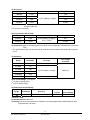
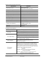
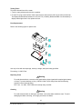
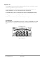
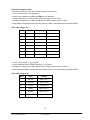
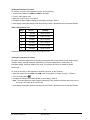
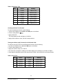
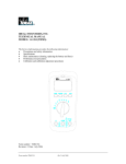
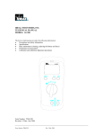
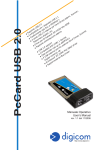
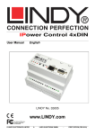
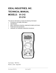
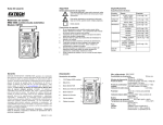
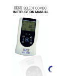
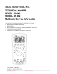
IDEAL INDUSTRIES, INC. TECHNICAL MANUAL
MODEL: 61-320
MODEL: 61-322
MODEL: 61-324
Multimeters Service Information
The Service Information provides the following information:
●
Precautions and safety information
●
Specifications
●
Basic maintenance (cleaning, replacing the battery and fuses)
●
Performance test procedures
●
Calibration and calibration adjustment procedures
Form Number: TM61320-2-4
Revision: 3. Date: Apr 2004
Form Number TM61320-2-4
Rev 3 April 2004
TABLE OF CONTENTS
Page
Introduction
1
Precautions and Safety Information
1
Symbols
1
Safety
2
Specifications
3
General Specification
3
Measurement Characteristics
4
Voltage Specification
4
Current Specifications
5
Resistance, Diode Specifications
5
Continuity, Frequency, Capacitance Specification
6
Auto Power Off, Peak Hold
6
Physical and environment characteristics
7
Certification and compliance
7
Required Equipment
8
Basic Maintenance
9
Opening the Meter Case
9
Replacing the Battery
9
Testing Fuses
10
Fuses Replacement
10
Replacing Fuses
10
Cleaning
10
Performance Tests
11
Testing the Display
11
Testing the Voltage Function
12
Testing the Resistance Function
13
Testing the Capacitance Function
13/14
Testing the Diode
14
Testing the milliamp (mA) Function
14/15
Testing the microamp Function
15
Testing the Frequency
15
Testing Frequency Function
15/16
Calibration
17
Calibrating DCV, ACV Functions
17
Calibration Adjustment Points
18/19
i
Form Number TM61320-2-4
Rev 3 April 2004
Introduction
Warning
To avoid shock or injury, do not perform the verification tests or calibration procedures
described in the manual unless you are qualified to do so.
The information provided in this document is for the use of qualified personnel only.
Caution
The 61-320 serials contain parts that can be damaged by static discharge.
Follow the standard practices for handling static sensitive devices.
For additional information about IDEAL INDUSTRIES, INC. and its products, and services, visit
IDEAL INDUSTRIES, INC. web site at:
www.idealindustries.com
Precautions and Safety Information
Use the Meter only as described in the Service Manual. If you do not do so, the protection provided by the
Meter may be impaired. Read the “Safety Information” page before servicing this product.
In this manual, a Warning identifies conditions and actions that pose hazard (s) to the user; a Caution
identifies conditions and actions that may damage the Meter or the test instruments.
The Symbols
The symbols used on the Meter and in this manual are explained in Table A.
Table A. The Symbols
Risk of electric shock
See instruction card
DC measurement
Equipment protected by double or reinforced
insulation
Battery
Earth
AC measurement
Conforms to EU directives
1
Form Number TM61320-2-4
Rev 3 April 2004
SAFETY
Review the following safety precautions to avoid injury and prevent damage to this product or any
products connected to it. To avoid potential hazards, use the product only as specified.
CAUTION: These statements identify conditions or practices that could result in damage to the
equipment or other property.
WARNING: These statements identify conditions or practices that could result in personal injury or
loss of life.
Specific precautions
Use proper Fuse. To avoid fire hazard, use only the fuse type and rating specified for this product.
Do not operate without covers. To avoid personal injury, do not apply any voltage or current to the
product without covers in place.
Electric overload. Never apply a voltage to a connector on the product that is outside the range specified
for that connector.
Avoid electric shock. To avoid injury or loss of life, do not connect or disconnect probes or test leads
while they are connected to a voltage source.
Do not operate in wet/damp conditions. To avoid electric shock, do not operate this product in wet or
damp conditions.
2
Form Number TM61320-2-4
Rev 3 April 2004
SPECIFICATIONS
All specifications are warranted unless noted typical and apply to the 61-320 & 61-322 & 61-324
Stated accuracies are at 23°C±5°C at less than 80% relative humidity and without the battery indicator
displayed.
General specifications
Characteristics
Description
Display count
3 3/4
Numeric update rate
1.5 times / sec
Polarity display
Automatic
Overrange display
“OL” is display
Low voltage indicator
is indicated
Automatic power-off time
Automatic backslit off = 30 minutes
Power source
9V×1 battery for 61-322 & 61-324;
1.5V×2 batteries for 61-320
Maximum input voltage
1000V CAT III between V and COM
Maximum floating voltage
1000V CAT III between any terminal and earth ground
Maximum input current
400mA between mA and COM
Maximum open circuit Voltage (current inputs)
600V between mA and COM
Overload protection mA connector
1A (600V) fast blow fuse.
V connector
V
Temperature Coefficient
0.2×(Spec. Accuracy) / °C, <18°C or >28°C
Battery Life
Alkaline 9V 200 hours for 61-322 & 61-324
Alkaline 1.5V×2 AA size 600 hours for 61-320
,V
3
Form Number TM61320-2-4
Rev 3 April 2004
, Ω,
,
,
, Hz, µA
Measurement Characteristics
Accuracy is ±(% reading + number of digits) at 23°C ± 5°C, less than 80% R.H.
(1) DC Volts
Range
Resolution
400.0mV
100µV
4.000V
1mV
40.00V
10mV
400.0V
100mV
1000V
1V
Accuracy
Over voltage
protection
±(0.5% reading + 2 digit)
1000V rms
Input Impedance: 10MΩ (over 1000MΩ in 400mV range).
(2) AC Volts
Over voltage
protection
Range
Resolution
Accuracy
400.0mV
100µV
Unspecified
4.000V
1mV
±(1.3% reading + 5 digits) *1
40.00V
10mV
400.0V
100mV
750V
1V
1000V rms
±(1.2% reading + 5 digits) *
2,3
Input Impedance: 10MΩ // less than 100pF.
*1 Frequency Response: 50Hz ~ 300Hz
*2 Frequency Response: 50Hz ~ 500Hz
CMRR / NMRR: (Common Mode Rejection Ratio)
(Normal Mode Rejection Ratio)
VAC: CMRR > 60dB at DC, 50Hz / 60Hz
VDC: CMRR > 100dB at DC, 50Hz / 60Hz
NMRR > 50dB at DC, 50Hz / 60Hz
AC Conversion Type: 61-320: Average sensing rms indication calibrated to the sine wave input.
61-322 / 61-324: AC conversions are ac-coupled, true rms responding, calibrated to
the sine wave input.
3
* 61-322 / 61-324 The specified accuracy is for sine wave at full scale and non-sine wave at half scale
with crest factor up to 2.
Crest Factor: C.F. = Peak/RMS
+1.5% addition error for C.F. from 1.4 to 3
+3.0% addition error for C.F. from 3 to 4.
4
Form Number TM61320-2-4
Rev 3 April 2004
(3) DC Current
Range
Resolution
400.0µA
0.1µA
4000µA
1µA
40.00mA*
10µA
400.0mA*
0.1mA
Accuracy
Voltage Burden
5mV
2V max.
±(1.0% reading + 2 digits)
5mV
2V max.
Overload Protection: mA Input : 1A (600V) fast blow fuse. (61-322 / 61-324)
µA Input : 600V rms.
* For 61-322 / 61-324 only.
(4) AC Current (61-322 / 61-324)
Range
Resolution
Accuracy
Voltage Burden
40.00mA
10µA
5mV
400.0mA
100µA
±(1.5% reading + 5 digits) *1
50Hz ~ 500Hz
2V max.
Overload Protection: mA Input : 1A (600V) fast blow fuse.
AC Conversion Type: AC conversions are ac-coupled, true rms responding, calibrated to the sine wave
input.
*1 The specified accuracy is for sine wave at full scale and non-sine wave at half scale with crest factor
up to 2.
(5) Resistance
Over voltage
protection
Range
Resolution
Accuracy
400.0Ω *1
0.1Ω
±(1.0% reading + 5 digits)
4.000KΩ
1Ω
40.00KΩ
10Ω
400.0KΩ
100Ω
4.000MΩ
40.00MΩ *
±(0.7% reading + 2 digits)
600V rms
1KΩ
2
10KΩ
±(1.5% reading + 5 digits)
Open circuit Voltage: -1.3V approx.
*1 < 5 digit of reading rolling.
*2 < 2% of reading rolling.
(6) Diode Check and Continuity
Range
Resolution
Accuracy
Max. Test
Current
Max. Open
Circuit Voltage
1mV
±(1.5% reading + 5 digits) *
1.5mA
3V
* For 0.4V ~ 0.8V
Overload Protection: 600V rms.
Continuity: Built-in buzzer sounds when resistance is less than approximately 450Ω Response time
is approximately 100 msec.
5
Form Number TM61320-2-4
Rev 3 April 2004
(7) Frequency
Range
Resolution
4.000KHz
1Hz
40.00KHz
10Hz
400.0KHz
100Hz
4.000MHz
1KHz
300mV rms
40.00MHz
10KHz
1V rms
Accuracy
Overload
protection
Frequency:
(± 0.01% + 1 digit)
600V rms
Sensitivity
150mV rms *
* Less than 20Hz, the sensitivity is 1.5V rms.
(8) Capacitance
Range
Resolution
4.000nF
1pF
40.00nF
10pF
400.0nF
100pF
4.000µF
1nF
40.00µF
10nF
400.0µF
Accuracy
Over voltage
Protection
±(3% reading + 10 digits)
±(2% reading + 8 digits)
600V rms
100nF
4.000mF *
1
40.00mF *
1
1µF
10µF
±(5% reading + 20 digits) *2
1
* In this range the reading maybe rolling within specification.
*2 Specify reading < half full scale of range.
(9) Auto Power Off (APO)
If the Meter idles for more than 30 minutes, the Meter automatically turns the power off.
(10) Peak Hold
Function
ACV
Range
Accuracy
400mV
Unspecified
4.000V
±(1.5% reading + 300 digits) *2
40.00V
400.0V
±(1.5% reading + 60 digits)
750V
ACA
(61-322/61-324)
40.00mA *3
400.0mA *3
±(3% reading + 60 digits)
Note:
1
With zero calibrated before measurement.
*2 4V range specifies readings above 10% of full scale of range.
*3 Amp range specify reading <90% of full scale of range.
4
In the noise generating field, may affect intervals.
6
Form Number TM61320-2-4
Rev 3 April 2004
Physical and Environmental Characteristics
Characteristics
Description
Dimensions (H×W×D)
158mm×76mm×38mm
164mm×82mm×44mm (with holster)
Weight (with battery)
0.3Kg
With holster
0.5Kg
Environmental characteristics
Description
Temperature operating
0 to +50°C
Non-Operating
-20 to +60°C
Humidity (operating)
<80% R.H.
Altitude Operating
2,000M (6560 ft.)
Non-Operating
12,300M (40354 ft.)
Vibration & shock Operating
MIL-T-28800E TYPE II Class 5
2.66gRMS, 5 to 500Hz, 3axes
(10 minutes each)
Indoor Use
Indoor Use
Certifications and compliances
Safety
Input rating
Designed to ICE 1010-1, UL3111-1 and CSA specifications
V / Ω/µA: Category III 1000 Volts
V / Ω/mA: Category III 600 Volts
CAT III: Distribution level mains, fixed installation.
Over voltage category
CAT II: Local level mains, appliances, portable equipment
CAT I: Signal level, special equipment or parts of equipment,
telecommunication, electronics.
Pollution Degree 2
Do not operate in environments where conductive
Pollutants may be present.
EC Declaration
of Conformity
Meets the intent of Directive 89/336/EEC for Electtromagnetic
Compatibility and Low Voltage Directive 73/23/EEC for product
safety. Compliance was demonstarted to the following specifications as listed in the official Journal of the European Communites:
En 55011 Class A: Radiated and Conducted
Emissions.
En 50082-1 Immunity: IEC 801-2 Electrostatic Discharge
IEC 801-3 RF Radiated
En 61010-1 Safety requirements for electrical equipment for
measurement, control, and laboratory use.
7
Form Number TM61320-2-4
Rev 3 April 2004
Required Equipment
Required equipment is listed in Table B. If the recommended models are not available, equipment with
equivalent specifications may be used.
Repairs or servicing should be performed only by qualified personnel.
Table B. Required Equipment
Equipment
Calibrator
Required Characteristics
AC Voltage Range: 0 ~ 750V AC
Accuracy: ±0.07% (Basic)
Frequency Range: 40 ~ 1KHz
Accuracy: ±2%
DC Voltage Range: 0 ~ 1000V DC
Accuracy: ±0.006% (Basic)
Current Range: 0 ~ 10A
Accuracy: AC (40Hz to 1KHz): ±0.08% (Basic)
DC: ±0.02% (Basic)
Frequency Source: 5.00Hz ~ 100MHz
Accuracy: ±0.001%
Amplitude: 0.5V p-p ~ 1.0V p-p (square wave)
Accuracy: ±5%
Resistance Range: 1Ω ~ 100MΩ
Accuracy: ±0.03% (Basic)
Capacitance Range: 1pF ~ 10mF
Accuracy: ±0.10% (Basic)
8
Form Number TM61320-2-4
Rev 3 April 2004
Recommended Model
Fluke 5500 or Wavetek
9100 Calibrator or
equipment
Basic Maintenance
Warning
To avoid shock, remove the test leads and any input signals before opening the case or replacing the
battery or fuses.
Opening the Meter Case
Caution
To avoid unintentional shock circuit, always place the uncovered Meter assembly on a protective surface.
When the case of the Meter is open, circuit connections are exposed.
To open the Meter case, refer Figure 1 and do the following:
1. Disconnect test leads from any live source, turn the rotary switch to OFF, and remove the test leads
from front terminals.
2. Remove the battery door by using a flat-blade screwdriver to turn the battery door screws turn
counter-clockwise.
3. The case bottom is secured to the case top by four screws and two internal snaps (at the LCD end).
Using a Phillips-had screwdriver, remove the four screws.
Replacing the Battery
The Meter is powered 1.5V x 2 batteries for 61-320 and a single 9V battery for 61-322 / 61-324.
To replace the battery, refer to Figure
9
Form Number TM61320-2-4
Rev 3 April 2004
Testing Fuses
To test the internal fuses of the meter.
1. Turn the rotary selector switch to the Ω position.
2. To test FS1, plug a test lead into VΩHz input terminal, and touch the probe to the mA input terminal.
The display should indicate between 0.0 to 0.2Ω. FS1 (1A 600V) (Bussmann BBS-1 recommended). If
display reads higher than 0.2Ω, replace the fuse.
Fuse Replacement
Refer to the following figure to replace fuse:
Use only a fuse with the amperage, interrupt, voltage, and speed rating specified.
Fuse rating: 1A, 600V, Fast
Replacing Fuses
Warning
To avoid electrical shock, remove the test leads and any input signals before replacing the battery
or fuses. To prevent damage or injury, INSTALL ONLY quick acting fuses with the following
Amp/Volt current interrupt rating :
FS1 Fuse : 1A, 600V, FAST. Minimum interrupt rating 10,000A
Cleaning
Warning
To avoid electrical shock or damage to the Meter, never allow water inside the case. To avoid
damaging the Meter’s housing, never apply solvents to the Meter.
10
Form Number TM61320-2-4
Rev 3 April 2004
Performance Tests
The following performance tests verify the complete operability of the Meter and check the accuracy of
each Meter function against the Meter’s specifications.
Accuracy specifications are valid for a period of one year after calibration, when measured at an
operating temperature of 18°C to 28°C and a maximum of 80% relative humidity.
To perform the following tests, it is not necessary to open the case, no Adjustments are necessary,
merely make the required connections, apply the designated inputs, determine if the reading on the
Meter display falls within the acceptable range indicated.
If the Meter fails any of these tests, it needs calibration adjustment or repair.
Testing the Display
Press “HOLD” key while turning the Meter on from the “OFF” position to hold the display in the Display
Test Mode. Compare the display with the example in Figure 2. Turn off the meter to escape the test
mode.
LCD Graphics 61-324
Figure 2 Display Test
11
Form Number TM61320-2-4
Rev 3 April 2004
Testing the Voltage Function
To verify accuracy in the AC and DC voltage ranges, do the following:
1. Turn the rotary switch to “V ” position.
2. Connect the Calibrator to the VΩ and COM inputs on the Meter.
3. Set the Calibrator for the voltage and frequency from step 1 to 8 in Table 1.
4. Compare the reading on the Meter display with the display reading shown in Table 1.
5. If the display reading falls outside of the range shown in Table 1, the Meter does not meet specification.
Table 1 AC Voltage Test:
Step
Input
Frequency
Reading
1
3.000V
50Hz
2.956 to 3.044
2
3.000V
500Hz
2.956 to 3.044
3
30.00V
50Hz
29.59 to 30.41
4
30.00V
500Hz
29.59 to 30.41
5
300.0V
50Hz
295.9 to 304.1
6
300.0V
500Hz
295.9 to 304.1
7
750V
50Hz
736 to 764
8
750V
500Hz
736 to 764
6. Turn the rotary switch to “V ” position.
7. Set the calibration for the voltage from step 1 to 6 in Table 2.
8. Compare the reading on the Meter display with the display reading shown in Table 2.
9. If the display reading falls outside of the range shown in Table 2, the meter does not meet specification.
Table 2 DC Voltage Test:
Step
Input
Reading
1
300.0mV
298.3 to 301.7
2
-300.0mV
-298.3 to -301.7
3
3.000V
2.983 to 3.017
4
30.00V
29.83 to 30.17
5
300.0V
298.3 to 301.7
6
1000V
993 to 1007
12
Form Number TM61320-2-4
Rev 3 April 2004
Testing the Resistance Function
To verify the accuracy of the resistance function, do the following:
1. Connect the Calibrator to VΩHz and COM on the Meter.
2. Turn the rotary switch to Ω.
3. Apply the inputs for step 1-6 in Table 3.
4. Compare the Meter display readings to the display readings in Table 3.
5. If the display reading falls outside of the range shown in Table 3, the Meter does not meet specification.
Table 3 Ω Resistance Test:
Step
Source
Reading
1
300.0Ω
296.5 to 303.5
2
3.000KΩ
2.977 to 3.023
3
30.00KΩ
29.77 to 30.23
4
300.0KΩ
297.7 to 302.3
5
3.000MΩ
2.977 to 3.023
6
30.00MΩ
29.50 to 30.50
Lead resistance on the 400Ω range is not included in error.
Testing the Capacitance Function
The Meter measures capacitance by charging the capacitor with a known Direct current, measuring the
resultant voltage, and calculating the capacitance. If the same capacitance is measured on an
impedance bridge, a different reading may result. This variance is likely to be Greater at higher
frequencies.
To verify the accuracy of the capacitance measuring function, do the Following :
1. Apply the Capacitor to the VΩHz and COM inputs on the Meter. For steps 1 through 7 in Table 4.
2. Turn the rotary switch
.
3. Compare the reading on the Meter display to the reading in Table 4.
Note : The meter selects the proper range automatically. Each measurement takes about one second
per range, 5mF takes about 4.5 seconds.
4. If the display reading falls outside of the range shown in Table 4, the Meter does not meet specification.
13
Form Number TM61320-2-4
Rev 3 April 2004
Table 4 Capacitance Test:
Step
Source
Reading
1
3.000nF
2.900 to 3.100
2
30.00nF
29.00 to 31.00
3
300.0nF
293.2 to 306.8
4
3.000µF
2.932 to 3.068
5
30.00µF
29.32 to 30.68
6
300.0µF
293.2 to 306.8
7
3.000mF
2.830 to 3.170
Checking the Diode Test Function
To check the diode test function, do the following:
1. Connect the Calibrator to the VΩHz and COM inputs on the Meter.
2. Turn the rotary switch to
.
3. Apply 3.000V DC.
The meter display should read approx. 3.000V dc.
4. Apply a 50Ω resistor to meter, the built-in beeper alarms.
Testing the milliamp (mA) Function (for 61-322 and 61-324)
To verify the accuracy of AC current measurement functions, do the following:
1.Connect the Calibrator to the mA and COM inputs on the Meter.
2. Turn the rotary switch to mA
3. Apply the inputs for steps 1-4 in Table 5.
4. For each input, compare the reading on the Meter display to the reading for your Meter in Table 5.
5. If the display reading falls outside of the range shown in Table 5, the meter does not meet specification.
Table 5 AC mA Test:
Step
Source
Frequency
1
30.00mA
50Hz
29.50 to 30.50
2
30.00mA
500Hz
29.50 to 30.50
3
300.0mA
50Hz
295.0 to 305.0
4
300.0mA
500Hz
295.0 to 305.0
14
Form Number TM61320-2-4
Rev 3 April 2004
Reading
6. Turn the rotary switch to mA .
7. Set the calibration for the voltage from step 1 - 2 in Table 6.
8. For each input, compare the reading on the Meter display to the reading in Table 2.
9. If the display reading falls outside of the range shown in Table 6, the meter does not meet specification.
Table 6 DC Current Test:
Step
Source
Reading
1
30.00mA
29.68 to 30.32
2
300.0mA
296.8 to 303.2
Testing the microamp Function
1. Turn the rotary switch to µA .
3. Apply the inputs for steps 1-2 in Table 7.
4. For each input, compare the reading on the Meter display to the reading for your Meter in Table 8.
5. If the display reading falls outside of the range shown in Table 7, the meter does not meet specification.
Table 7 DC microamp Test:
Step
Source
Reading
1
300.0µA
296.8 to 303.2
2
3000µA
2968 to 3032
Testing the Frequency Function
To verify the accuracy of the Meter’s frequency function, do the following:
1. Connect the Calibrator to the VΩ and COM inputs on the Meter.
Note: The accuracy of the Calibrator’s frequency function must be appropriate for the specified
accuracy of the Meter.
2. Set the rotary switch to Hz.
3. Set the Function Generator for the square wave voltage and frequency for steps 1-5 of Table 8.
4. Compare the reading on the Meter display with the display reading shown in Table 8.
5. If the display reading falls outside of the range shown in Table 8, the Meter does not meet specification.
15
Form Number TM61320-2-4
Rev 3 April 2004
Table 8 Frequency Test:
Step
Soure
Level
Reading
1
3.000KHz
150mV rms
2.999 to 3.001
2
30.00KHz
150mV rms
29.99 to 30.01
3
300.0KHz
150mV rms
299.9 to 300.1
4
3.000MHz
300mV rms
2.999 to 3.001
5
30.00MHz
1V rms
29.99 to 30.01
16
Form Number TM61320-2-4
Rev 3 April 2004
Calibration Procedure
Recalibrate your meter:
It is recommended that the multimeter be calibrated once each year.
1. Perform calibration at an ambient temperature of 23°C±2°C and a relative humidity of 73% or less.
2. Disconnect the test leads and turn the meter off Remove the test leads from the front terminals.
3. Position the meter face down. Remove the three screws from the case bottom.
4. Lift the end of the case bottom until it gently unsnaps from the case top at the end nearest the LCD.
5. Lift the circuit board from the case top. Do not remove the screws from the circuit board.
(A) DCV Calibration (Adjust VR1)
1. Set the circuit board rotary switch "arrow" to the "V" position of circuit board.
2. Set the output of DC calibrator for 300.0V±0.02% and connect to VΩHz and COM input terminals on
meter.
3. Using a small flat-tipped screwdriver adjust the potentiometer VR1 until the display reads 299.0 or 300.1.
4. Disconnect the DC calibrator from the meter.
(B) ACV Calibration (Adjust VR2)
1. Set the circuit board rotary switch "arrow" to the "V" position of circuit board.
2. Set the output of AC calibration for 300Vrms 50Hz (61-320) 300Vrms 50Hz (61-322/61-324) and
connect to VΩHz and COM input terminals on meter.
3. Using a small flat-tipped screwdriver adjust the potentiometer VR2 until the display reads 299.9 or
300.1 (61-320) 299.9 or 300.1 (61-322/61-324).
17
Form Number TM61320-2-4
Rev 3 April 2004
VR1
VR2
Figure 3 61-320 Calibration Adjustment Points
18
Form Number TM61320-2-4
Rev 3 April 2004
VR1
VR2
Figure 4 61-322/324 Calibration Adjustment Points
19
Form Number TM61320-2-4
Rev 3 April 2004